US9227444B1 - Inkjet print heads alignment assembly, kits and methods - Google Patents
Inkjet print heads alignment assembly, kits and methods Download PDFInfo
- Publication number
- US9227444B1 US9227444B1 US14/673,139 US201514673139A US9227444B1 US 9227444 B1 US9227444 B1 US 9227444B1 US 201514673139 A US201514673139 A US 201514673139A US 9227444 B1 US9227444 B1 US 9227444B1
- Authority
- US
- United States
- Prior art keywords
- assembly
- phase
- sled
- stage
- carriage
- Prior art date
- Legal status (The legal status is an assumption and is not a legal conclusion. Google has not performed a legal analysis and makes no representation as to the accuracy of the status listed.)
- Expired - Fee Related
Links
- 238000000034 method Methods 0.000 title abstract description 11
- RKTYLMNFRDHKIL-UHFFFAOYSA-N copper;5,10,15,20-tetraphenylporphyrin-22,24-diide Chemical compound [Cu+2].C1=CC(C(=C2C=CC([N-]2)=C(C=2C=CC=CC=2)C=2C=CC(N=2)=C(C=2C=CC=CC=2)C2=CC=C3[N-]2)C=2C=CC=CC=2)=NC1=C3C1=CC=CC=C1 RKTYLMNFRDHKIL-UHFFFAOYSA-N 0.000 claims description 16
- 230000000630 rising effect Effects 0.000 claims description 4
- 230000000712 assembly Effects 0.000 abstract description 19
- 238000000429 assembly Methods 0.000 abstract description 19
- 230000008878 coupling Effects 0.000 description 5
- 238000010168 coupling process Methods 0.000 description 5
- 238000005859 coupling reaction Methods 0.000 description 5
- 238000009472 formulation Methods 0.000 description 2
- 230000014759 maintenance of location Effects 0.000 description 2
- 238000004519 manufacturing process Methods 0.000 description 2
- 239000000203 mixture Substances 0.000 description 2
- 230000006978 adaptation Effects 0.000 description 1
- 239000000853 adhesive Substances 0.000 description 1
- 230000001070 adhesive effect Effects 0.000 description 1
- 210000004712 air sac Anatomy 0.000 description 1
- 230000009286 beneficial effect Effects 0.000 description 1
- 230000015556 catabolic process Effects 0.000 description 1
- 238000006243 chemical reaction Methods 0.000 description 1
- 238000007906 compression Methods 0.000 description 1
- 230000006835 compression Effects 0.000 description 1
- 238000006731 degradation reaction Methods 0.000 description 1
- 230000005672 electromagnetic field Effects 0.000 description 1
- 238000005259 measurement Methods 0.000 description 1
- 239000002184 metal Substances 0.000 description 1
- 150000003071 polychlorinated biphenyls Chemical class 0.000 description 1
- 230000000284 resting effect Effects 0.000 description 1
- 239000000758 substrate Substances 0.000 description 1
- 230000000930 thermomechanical effect Effects 0.000 description 1
Images


Classifications
-
- B—PERFORMING OPERATIONS; TRANSPORTING
- B41—PRINTING; LINING MACHINES; TYPEWRITERS; STAMPS
- B41J—TYPEWRITERS; SELECTIVE PRINTING MECHANISMS, i.e. MECHANISMS PRINTING OTHERWISE THAN FROM A FORME; CORRECTION OF TYPOGRAPHICAL ERRORS
- B41J25/00—Actions or mechanisms not otherwise provided for
- B41J25/304—Bodily-movable mechanisms for print heads or carriages movable towards or from paper surface
- B41J25/308—Bodily-movable mechanisms for print heads or carriages movable towards or from paper surface with print gap adjustment mechanisms
-
- B—PERFORMING OPERATIONS; TRANSPORTING
- B41—PRINTING; LINING MACHINES; TYPEWRITERS; STAMPS
- B41J—TYPEWRITERS; SELECTIVE PRINTING MECHANISMS, i.e. MECHANISMS PRINTING OTHERWISE THAN FROM A FORME; CORRECTION OF TYPOGRAPHICAL ERRORS
- B41J2/00—Typewriters or selective printing mechanisms characterised by the printing or marking process for which they are designed
- B41J2/005—Typewriters or selective printing mechanisms characterised by the printing or marking process for which they are designed characterised by bringing liquid or particles selectively into contact with a printing material
- B41J2/01—Ink jet
- B41J2/015—Ink jet characterised by the jet generation process
- B41J2/04—Ink jet characterised by the jet generation process generating single droplets or particles on demand
- B41J2/045—Ink jet characterised by the jet generation process generating single droplets or particles on demand by pressure, e.g. electromechanical transducers
- B41J2/04501—Control methods or devices therefor, e.g. driver circuits, control circuits
- B41J2/04505—Control methods or devices therefor, e.g. driver circuits, control circuits aiming at correcting alignment
-
- B—PERFORMING OPERATIONS; TRANSPORTING
- B41—PRINTING; LINING MACHINES; TYPEWRITERS; STAMPS
- B41J—TYPEWRITERS; SELECTIVE PRINTING MECHANISMS, i.e. MECHANISMS PRINTING OTHERWISE THAN FROM A FORME; CORRECTION OF TYPOGRAPHICAL ERRORS
- B41J2/00—Typewriters or selective printing mechanisms characterised by the printing or marking process for which they are designed
- B41J2/005—Typewriters or selective printing mechanisms characterised by the printing or marking process for which they are designed characterised by bringing liquid or particles selectively into contact with a printing material
- B41J2/01—Ink jet
- B41J2/015—Ink jet characterised by the jet generation process
- B41J2/04—Ink jet characterised by the jet generation process generating single droplets or particles on demand
- B41J2/045—Ink jet characterised by the jet generation process generating single droplets or particles on demand by pressure, e.g. electromechanical transducers
- B41J2/04501—Control methods or devices therefor, e.g. driver circuits, control circuits
- B41J2/04506—Control methods or devices therefor, e.g. driver circuits, control circuits aiming at correcting manufacturing tolerances
-
- B—PERFORMING OPERATIONS; TRANSPORTING
- B41—PRINTING; LINING MACHINES; TYPEWRITERS; STAMPS
- B41J—TYPEWRITERS; SELECTIVE PRINTING MECHANISMS, i.e. MECHANISMS PRINTING OTHERWISE THAN FROM A FORME; CORRECTION OF TYPOGRAPHICAL ERRORS
- B41J2/00—Typewriters or selective printing mechanisms characterised by the printing or marking process for which they are designed
- B41J2/005—Typewriters or selective printing mechanisms characterised by the printing or marking process for which they are designed characterised by bringing liquid or particles selectively into contact with a printing material
- B41J2/01—Ink jet
- B41J2/17—Ink jet characterised by ink handling
- B41J2/175—Ink supply systems ; Circuit parts therefor
- B41J2/17503—Ink cartridges
- B41J2/1752—Mounting within the printer
-
- B—PERFORMING OPERATIONS; TRANSPORTING
- B41—PRINTING; LINING MACHINES; TYPEWRITERS; STAMPS
- B41J—TYPEWRITERS; SELECTIVE PRINTING MECHANISMS, i.e. MECHANISMS PRINTING OTHERWISE THAN FROM A FORME; CORRECTION OF TYPOGRAPHICAL ERRORS
- B41J2/00—Typewriters or selective printing mechanisms characterised by the printing or marking process for which they are designed
- B41J2/005—Typewriters or selective printing mechanisms characterised by the printing or marking process for which they are designed characterised by bringing liquid or particles selectively into contact with a printing material
- B41J2/01—Ink jet
- B41J2/17—Ink jet characterised by ink handling
- B41J2/175—Ink supply systems ; Circuit parts therefor
- B41J2/17503—Ink cartridges
- B41J2/17553—Outer structure
-
- B—PERFORMING OPERATIONS; TRANSPORTING
- B41—PRINTING; LINING MACHINES; TYPEWRITERS; STAMPS
- B41J—TYPEWRITERS; SELECTIVE PRINTING MECHANISMS, i.e. MECHANISMS PRINTING OTHERWISE THAN FROM A FORME; CORRECTION OF TYPOGRAPHICAL ERRORS
- B41J2/00—Typewriters or selective printing mechanisms characterised by the printing or marking process for which they are designed
- B41J2/315—Typewriters or selective printing mechanisms characterised by the printing or marking process for which they are designed characterised by selective application of heat to a heat sensitive printing or impression-transfer material
- B41J2/32—Typewriters or selective printing mechanisms characterised by the printing or marking process for which they are designed characterised by selective application of heat to a heat sensitive printing or impression-transfer material using thermal heads
- B41J2/335—Structure of thermal heads
- B41J2/33575—Processes for assembling process heads
-
- B—PERFORMING OPERATIONS; TRANSPORTING
- B41—PRINTING; LINING MACHINES; TYPEWRITERS; STAMPS
- B41J—TYPEWRITERS; SELECTIVE PRINTING MECHANISMS, i.e. MECHANISMS PRINTING OTHERWISE THAN FROM A FORME; CORRECTION OF TYPOGRAPHICAL ERRORS
- B41J2/00—Typewriters or selective printing mechanisms characterised by the printing or marking process for which they are designed
- B41J2/485—Typewriters or selective printing mechanisms characterised by the printing or marking process for which they are designed characterised by the process of building-up characters or image elements applicable to two or more kinds of printing or marking processes
- B41J2/505—Typewriters or selective printing mechanisms characterised by the printing or marking process for which they are designed characterised by the process of building-up characters or image elements applicable to two or more kinds of printing or marking processes from an assembly of identical printing elements
- B41J2/51—Typewriters or selective printing mechanisms characterised by the printing or marking process for which they are designed characterised by the process of building-up characters or image elements applicable to two or more kinds of printing or marking processes from an assembly of identical printing elements serial printer type
- B41J2/512—Adjustment of the dot disposition by adjustment of the arrangement of the dot printing elements of a print head, e.g. nozzles, needles
-
- B—PERFORMING OPERATIONS; TRANSPORTING
- B41—PRINTING; LINING MACHINES; TYPEWRITERS; STAMPS
- B41J—TYPEWRITERS; SELECTIVE PRINTING MECHANISMS, i.e. MECHANISMS PRINTING OTHERWISE THAN FROM A FORME; CORRECTION OF TYPOGRAPHICAL ERRORS
- B41J25/00—Actions or mechanisms not otherwise provided for
- B41J25/001—Mechanisms for bodily moving print heads or carriages parallel to the paper surface
-
- B—PERFORMING OPERATIONS; TRANSPORTING
- B41—PRINTING; LINING MACHINES; TYPEWRITERS; STAMPS
- B41J—TYPEWRITERS; SELECTIVE PRINTING MECHANISMS, i.e. MECHANISMS PRINTING OTHERWISE THAN FROM A FORME; CORRECTION OF TYPOGRAPHICAL ERRORS
- B41J25/00—Actions or mechanisms not otherwise provided for
- B41J25/304—Bodily-movable mechanisms for print heads or carriages movable towards or from paper surface
- B41J25/308—Bodily-movable mechanisms for print heads or carriages movable towards or from paper surface with print gap adjustment mechanisms
- B41J25/3086—Bodily-movable mechanisms for print heads or carriages movable towards or from paper surface with print gap adjustment mechanisms with print gap adjustment means between the print head and its carriage
-
- B—PERFORMING OPERATIONS; TRANSPORTING
- B41—PRINTING; LINING MACHINES; TYPEWRITERS; STAMPS
- B41J—TYPEWRITERS; SELECTIVE PRINTING MECHANISMS, i.e. MECHANISMS PRINTING OTHERWISE THAN FROM A FORME; CORRECTION OF TYPOGRAPHICAL ERRORS
- B41J25/00—Actions or mechanisms not otherwise provided for
- B41J25/304—Bodily-movable mechanisms for print heads or carriages movable towards or from paper surface
- B41J25/308—Bodily-movable mechanisms for print heads or carriages movable towards or from paper surface with print gap adjustment mechanisms
- B41J25/3088—Bodily-movable mechanisms for print heads or carriages movable towards or from paper surface with print gap adjustment mechanisms with print gap adjustment means on the printer frame, e.g. for rotation of an eccentric carriage guide shaft
-
- B—PERFORMING OPERATIONS; TRANSPORTING
- B41—PRINTING; LINING MACHINES; TYPEWRITERS; STAMPS
- B41J—TYPEWRITERS; SELECTIVE PRINTING MECHANISMS, i.e. MECHANISMS PRINTING OTHERWISE THAN FROM A FORME; CORRECTION OF TYPOGRAPHICAL ERRORS
- B41J25/00—Actions or mechanisms not otherwise provided for
- B41J25/34—Bodily-changeable print heads or carriages
-
- B—PERFORMING OPERATIONS; TRANSPORTING
- B41—PRINTING; LINING MACHINES; TYPEWRITERS; STAMPS
- B41J—TYPEWRITERS; SELECTIVE PRINTING MECHANISMS, i.e. MECHANISMS PRINTING OTHERWISE THAN FROM A FORME; CORRECTION OF TYPOGRAPHICAL ERRORS
- B41J2202/00—Embodiments of or processes related to ink-jet or thermal heads
- B41J2202/01—Embodiments of or processes related to ink-jet heads
- B41J2202/19—Assembling head units
Definitions
- the disclosure is directed to assembly for aligning inkjet printheads. More specifically, the disclosure is directed to inkjet printheads alignment system providing alignment of up to three (3) degrees of freedom.
- drop placement accuracy can be important.
- causes for inaccuracies in drop placement may include misalignment between printheads in an array, as well as misalignment of a substrate to be printed upon.
- a three dimension printhead aligning assembly comprising: a mounting platform having a front stage, a back stage and a pair of side rails connecting the front and back stages, the mounting platform comprising two linear phase actuators and defining an internal tetragonal space; a carriage operably coupled to the mounting platform, the carriage further comprising a phase translation anchor and a registration actuator; a sled, the sled nested within—and operably coupled to, the carriage; and an inkjet printheads, the printhead operably coupled to the sled respectively, wherein the assembly is configured to provide three degrees of freedom alignment of the printheads relative to the printing direction and optionally, with respect to a second printhead.
- kits comprising: a mounting platform having a front stage, a back stage and a pair of side rails connecting the front and back stages; a carriage; a sled; and an inkjet printhead, the mounting platform, carriage, sled and inkjet printhead configured to be assembled to form a three degrees of freedom printhead aligning assembly
- FIG. 1 illustrates an exploded isometric view of an embodiment of the assembly for inkjet printheads alignment
- FIG. 2 illustrates an exploded left side elevation view of an embodiment of the assembly for inkjet printheads alignment illustrated in FIG. 1 ;
- FIG. 3 illustrates an exploded front elevation view of an embodiment of the assembly for inkjet printheads alignment illustrated in FIG. 1 ;
- FIG. 4 illustrates a front elevation view of an embodiment of the mounting platform illustrated in FIG. 1 ;
- FIG. 5 illustrates a schematic X-Z cross section C-C view of an embodiment of the mounting platform illustrated in FIG. 4 ;
- FIG. 6 illustrates a front elevation view of the embodiment of the mounting platform illustrated in FIG. 4 ;
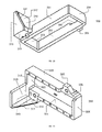
- FIG. 7 illustrates a top isometric view of an embodiment of the carriage:
- FIG. 8 illustrates a top plan view of the embodiment of the carriage illustrated in FIG. 7 ;
- FIG. 9 A illustrates a side elevation view of an embodiment of the carriage illustrated in FIG. 7
- FIG. 9B illustrates a front elevation view thereof
- FIG. 10 illustrates a bottom isometric view of an embodiment of the sled
- FIG. 11 illustrates a top/side isometric view of the sled embodiment illustrated in FIG. 10 ;
- FIG. 12 illustrates an isometric view of an embodiment of the cube-shaped alignment nut
- FIG. 13 illustrates a schematic X-Y cross section A-A view of the embodiment of the cube-shaped alignment nut illustrated in FIG. 12 .
- a three dimension printheads aligning assembly comprising: a mounting platform having a front stage, a back stage and a pair of side rails connecting the front and back stages, the mounting platform comprising at least two linear phase actuators and defining at least two internal tetragonal spaces; twoa carriage operably coupled to the mounting platform, the carriage further comprising a phase translation anchor and a registration actuator; twoa sled, the sled nested within—and operably coupled to, the carriage; and twoan inkjet printhead, the printhead operably coupled to the sled, wherein the assembly is configured to provide three degrees of freedom alignment of the printhead relative to the printing direction, and optionally with respect to a second printhead.
- the alignment assembly can be adapted to accurately print “drop-over-drop” of ink from two different types of printheads, for example, a first conductive ink followed exactly on the same printing pattern with insulating ink, while leaving certain section non-insulated. Further printheads can be installed on the same platform using the same configuration.
- An orifice plate can be located on the printing side (lower surface) of the printinghead, providing access for the nozzles to print, while potentially also providing protection for the printing head. Jetted ink from each nozzle can exits the orifice for printing. Further, the more closely packed the nozzles of an array are, the better the print quality that can be achieved. Likewise, where the nozzle is displaceable, ink is ejected from the nozzle at a slight angle. Conversely, if nozzles in the array are directed to be displaced in opposite directions, i.e. as mirror images of one another, the ink droplets ejected from such nozzles are offset with respect to the perpendicular to a greater extent. This may result in a degradation of the print quality.
- directional or positional terms such as “top”, “bottom”, “upper,” “lower,” “side,” “front,” “frontal,” “forward,” “rear,” “rearward,” “back,” “trailing,” “above,” “below,” “left,” “right,” “radial,” “vertical,” “upward,” “downward,” “outer,” “inner,” “exterior,” “interior,” “intermediate,” etc., are merely used for convenience in describing the various embodiments of the present disclosure.
- Coupled refers to and comprises any direct or indirect, structural coupling, connection or attachment, or adaptation or capability for such a direct or indirect structural or operational coupling, connection or attachment, including integrally formed components and components which are coupled via or through another component or by the forming process (e.g., an electromagnetic field).
- Indirect coupling may involve coupling through an intermediary member or adhesive, or abutting and otherwise resting against, whether frictionally (e.g., against a wall) or by separate means without any physical connection.
- engage and various forms thereof, when used with reference to retention of a member (e.g., the detent), refer to the application of any forces that tend to hold two components together against inadvertent or undesired separating forces (e.g., such as may be introduced during use of either component). It is to be understood, however, that engagement does not in all cases require an interlocking connection that is maintained against every conceivable type or magnitude of separating force.
- engaging element or “engaging member” refers to one or a plurality of coupled components, at least one of which is configured for releasably engaging a tab or detent.
- the adjustment box can be considered an engaging element.
- the term “sled” as used herein should be broadly construed to mean a device which is moveable in the length direction of the corresponding rail.
- the sled and the rail may have one of many different forms in order to achieve this.
- a person skilled in the art may choose a suitable form for the sled.
- the term “carriage” shall be broadly defined to include any component designed to carry something on or along something else.
- the term “carriage member” refers to any member that translates the motion of a moving drive member into motion of an object that is mechanically coupled to the carriage member (e.g., the sled).
- actuator refers to a device or assembly for imparting movement.
- the term actuator also refers generally to any of a number of actuation devices which may be utilized in articulating various components (e.g., the carriage and/or the sled) in the disclosed alignment assembly.
- electromechanical linear actuators, pneumatic cylinders, hydraulic cylinders, and air bladders are all contemplated as being applicable to one or more of the embodiments disclosed hereinbelow.
- actuators may include other combinations of prime movers and links or members which may be utilized to actuate, move, transfer motion, articulate, lift, lower, rotate, extend, retract, or otherwise move links, linkages, platforms, stages, frames, carriages, sleds or any of the members of the alignment assembly discussed.
- the term “about” means that amounts, sizes, formulations, parameters, and other quantities and characteristics are not and need not be exact, but may be approximate and/or larger or smaller, as desired, reflecting tolerances, conversion factors, rounding off, measurement error and the like, and other factors known to those of skill in the art. In general, an amount, size, formulation, parameter or other quantity or characteristic is “about” or “approximate” whether or not expressly stated to be such.
- shapes are provided, for example, quadrilateral, tetragonal, rectangle, trapezoid, other shapes and polygons are likewise encompassed. So for example, a “substantially rectangular frame” can likewise be square, or for that matter, oval. determination of the shape of each frame will be made based on overall assembly constraints.
- FIG. are merely schematic representations (e.g., illustrations) based on convenience and the ease of demonstrating the present disclosure, and are, therefore, not intended to indicate relative size and dimensions of the devices or components thereof and/or to define or limit the scope of the exemplary embodiments.
- the printheads aligning assembly 10 can comprise mounting platform 100 two (2) carriages 200 (or only one in another embodiment), operably coupled to mounting platform 100 , each carriage 200 further comprising a phase translation anchor 630 and a registration actuator (not shown, see e.g., FIG. 2 ).
- System 10 can further comprise two (2) sleds 300 (or only one in another embodiment), each sled nested within—and operably coupled to, each of carriages 200 respectively; and two (2) inkjet printheads 500 (or only one in another embodiment), each printhead 500 operably coupled to each of sleds 300 respectively, via base 400 , wherein assembly 10 is configured to provide three (3) degrees of freedom alignment of each of printheads 500 with respect to each other, and/or relative to the printing direction for each head. Also shown in FIG. 1 , is cube-shaped alignment nut 600 .
- alignment assembly 10 can be configured to provide each of printing head(s) 500 with as much as two degrees of freedom in Cartesian coordinates system and one degree of freedom in spherical coordinate system, resulting in a capability for aligning each of printheads 500 with three (3) DOF.
- the three degrees of freedom can be phase alignment (e.g., in the X direction, parallel with the printing direction or side-to-side), registration (e.g., in the Y direction, normal [90°] to the printing direction or front-to-back) and/or yaw (e.g., turn about a vertical axis at an angle ⁇ , or angular movement in the Y-Z plane) or any permutation of the foregoing.
- X-direction Y-direction
- Z-direction are interchangeably used with the corresponding terms “x-axis”, “y-axis”, and “z-axis”, where the axis are directions of the Cartesian coordinate system.
- mounting platform 100 can have having front stage 101 F, having an upper surface, a lower surface with a forward facing surface and internally facing surface 120 F (or 120 B) facing a quadrilateral opening 150 (other shaped opening can also be used).
- Mounting platform 100 can also have back stage 101 B having an upper surface, a lower surface a rear facing surface and internally facing surface 120 B facing quadrilateral opening 150 .
- mounting platform 100 can have and side rails 102 connecting the front and back stages 101 F, 101 B.
- Mounting platform 100 comprising at least two (2), linear phase actuators (not shown, see e.g., FIG. 1 with four linear phase actuators) and defining an internal quadrilateral space 150 (see e.g., FIG. 4 ).
- front stage 101 F and back stage 101 B of mounting platform 100 used in the alignment assemblies described herein can comprise plurality of parallel tetragonal recess pairs 103 p , 104 q .
- the pair of front and back tetragonal p th , q th recesses can be configured to receive and engage at least a portion of carriage 200 (See e.g., FIGS. 1 , 3 , and 9 A) and the linear phase actuator.
- the p th , q th tetragonal (in other words, having a general cage geometry) recess 103 p , 104 q can define top opening 110 to the upper surface of front stage 101 F and the upper surface of back stage 101 B.
- front stage 101 F tetragonal recess 103 p can further define front opening 112 (see e.g., FIGS. 5-6 ) to the forward facing surface (see e.g., FIG. 6 ), and each of back stage 101 B tetragonal recess 104 q can define a rear opening 111 to the rear facing surface (see e.g., FIG. 1 ).
- front stage bore 105 m and back stage bore 106 n of the mounting platform 100 used in the alignment assemblies described herein can be disposed between each front stage 101 F recess 103 p , back stage 101 B recess 104 q and the internal space defined by front stage 101 F, back stage 101 B and the side rails 102 .
- bores 105 m , 106 n can be disposed at the center of the upper surface opening 110 , and form an anchor point for carriage 200 (see e.g., FIG., element 630 ).
- carriage 200 can have a substantially rectangular frame having a longitudinal axis (not shown) with pair of long longitudinal side walls 240 , 241 connected by shorter front 242 and back 243 transverse walls (see e.g., FIG. 7 ).
- the frame can have other polygonal shapes and internal opening shapes.
- the 240 , 241 , 242 , and 243 walls are illustrated as rising from the edges of a substantially rectangular floor plate 250 defining a substantially rectangular opening 260 therein.
- the floor can be considered a ledge to receive and support sled 300 (see e.g., FIG.
- side walls 240 , and 241 can be configured to have a top portion aligned with the top portion 301 , 302 of sled 300 , and slidably couple to npreinhead 500 rails 501 (see e.g., FIG. 1 ).
- Carriage 200 used in the alignment assemblies described herein can comprise front 220 A and back 220 B extension slabs, each having an upper surface and a lower surface. Front 220 A and a back 220 B extension slabs can each further defining slit 221 A, 221 B therein, configured to accommodate the phase translation anchor. As illustrated, slits 221 A and 221 B are elongated (e.g., having an aspect ratio>1), with a longitudinal axis of the opening (major axis) that is normal to the longitudinal axis of the carriage. The length of the openings' major axis can be used and modified to predetermine the carriage phase movement (e.g., in the x-axis).
- Carriage 200 can further comprise front 210 A and back 210 B; phase and/or yaw adjustment tabs extending downward (see e.g., FIG. 8 ) from the lower surface of each front 220 A and back 220 B extension slab respectively.
- Front and back phase and/or yaw adjustment tabs 210 A, 210 B each have respectively a beveled internal wall 211 and a straight external wall 212 , defining a right angle trapezoid X-Y cross section. (see e.g., FIG. 3 , 7 , 9 A, 9 B).
- registration actuator housing is a tetragonal structure having a side wall that rises above the edge of each extension slab 220 A, 220 B, with an outward (to the front or rear) facing wall defining a threaded aperture 231 A, 231 B, and an open inward (to internal space 260 formed by carriage 200 walls) facing space.
- the term “accommodate” refers to the ability of an accommodating element to allow passage or retention of another element at close tolerance, without substantial space for other elements or components.
- front transverse wall 242 and back transverse wall 243 of carriage 200 used in the alignment assemblies described herein can each further define a basal aperture 245 A, 245 B, configured to receive and accommodate at least a portion of the phase actuator. (see e.g., FIG. 3 ).
- front 210 A and back 210 B phase and/or yaw adjustment tabs extending downward from the lower surface of each front 220 A and back 220 B extension slab respectively define a right angle trapezoid X-Y cross section, with external wall 212 , configured to abut a portion of the phase actuator, such as phase biasing elements 605 A, 605 B.
- Phase biasing elements 605 A, 605 B can be (leaf e.g.,) springs, rubber rods or similar biasing elements and operate to bias adjustment tabs 210 A, 210 B away from the side walls of tetragonal recess pairs 103 p and 104 q disposed in front stage 101 F and back stage 101 B of mounting platform 100 .
- biasing element refers to any device that provides a biasing force.
- biasing elements include but are not limited to springs (e.g., elastomeric or metal springs, torsion springs, coil springs, leaf springs, tension springs, compression springs, extension springs, spiral springs, volute springs, flat springs, and the like), detents (e.g., spring-loaded detent balls, cones, wedges, cylinders, and the like), pneumatic devices, hydraulic devices, and the like, and combinations thereof.
- springs e.g., elastomeric or metal springs, torsion springs, coil springs, leaf springs, tension springs, compression springs, extension springs, spiral springs, volute springs, flat springs, and the like
- detents e.g., spring-loaded detent balls, cones, wedges, cylinders, and the like
- pneumatic devices e.g., pneumatic devices, hydraulic devices, and the like, and combinations thereof.
- sled 300 used in the alignment assemblies described herein can define substantially rectangular open frame having a first 301 and second 302 long longitudinal side walls connected by shorter front 303 and back 304 transverse walls.
- Sled 300 can also comprise a generally L-shaped top plan view overhang 310 having an anterior wall 312 facing forward, wall 312 has an anterior surface extending above and continuous with front wall 303 of sled 300 , with side wall 313 , both walls ( 312 , 313 ) rising from a base plate 314 extending laterally outward (in other words hanging over side wall 301 ) from the sled first longitudinal side wall 301 .
- sled 300 can comprise ledge 305 extending laterally outward from the sled second longitudinal side wall 302 , the ledge disposed toward the back transverse wall 304 of the sled 300 . As illustrated (see e.g., FIG. 13 ), ledge 305 is recessed somewhat relative to the rim of side wall 302 at the corner of side wall 302 and back transverse wall 304 .
- FIGS. 1-3 illustrating that printhead 500 used in the alignment assemblies described herein, can be operably coupled to base 400 , wherein base 400 has anterior face 401 A (see e.g., FIG. 1 ) and posterior face (not shown), base 400 comprising anterior tag 405 extending laterally from anterior face 401 A, tag 405 configured to align with sled's 300 overhang 310 base plate 314 and couple thereto.
- Rails 501 (see e.g., FIG. 1 ), are adapted to operably slidably couple to sled 300 side walls ( 301 , 302 ), as well as side walls 240 , 241 of carriage 200 and provide the registration of printheads 500 .
- the phase actuator used in the alignment assemblies described herein can comprise a cube-shaped nut 600 (see e.g., FIGS. 1 , 12 ) defining a threaded cylindrical aperture 646 ( FIG. 12 ), extending through from front facet 640 to rear facet 641 , parallel top facet 645 and bottom facet 644 , and parallel left facet 642 and right facet 643 .
- front facet 640 can be larger than the rear facet 641 , such that top facet 645 and bottom facet 644 define a cross section (see e.g., FIG.
- right facet 643 can further define a rail, 647 extending vertically along straight right facet 643 having a generally trapezoidal cross section (see e.g., FIG. 13 ).
- the phase actuator used in the alignment assemblies described herein can also have phase calibration detent 601 .
- Detent 601 e.g., which an element configured to fit into a notch, pocket, bore, depression and the like, locking or unlocking movement
- head portion 602 e.g., configured to receive an adjustment tool, for example, an ELLENTM wrench
- blunt tip 604 e.g., blunt tip 604 and threaded portion 603 therebetween.
- Detent 601 can be configured to couple cube-shaped nut 600 , to carriage 200 ; for example through bore 245 , providing a fulcrum for the phase translation of carriage 200 in mounting platform 100 .
- phase biasing element 605 A can be adapted to abut external surface 212 of front and back phase adjustment tabs 210 A, 210 B, and bias front and back phase adjustment tabs 210 A, 210 B from the wall of tetragonal recess pairs 103 p , and 104 q .
- an Detent 601 can be used in the phase actuator and can comprise; head portion 602 (e.g., configured to receive an adjustment tool, for example, a PHILLIPSTM screw driver), blunt tip 604 and threaded portion 603 disposed therebetween.
- head portion 602 e.g., configured to receive an adjustment tool, for example, a PHILLIPSTM screw driver
- blunt tip 604 e.g., blunt tip 604 and threaded portion 603 disposed therebetween.
- Beveled facet 642 of cube-shaped nut 600 can be positioned to abut beveled surface 211 of front and back phase adjustment tabs 210 A, 210 B, such that rotating detent 601 rotatably coupled to basal aperture 245 A, 245 B defined respectively in front transverse wall 242 and back transverse wall 243 , causes cube-shaped nut 600 to slide against beveled internal surface 211 of carriage 200 front and back phase adjustment tabs 210 A, 210 B, translating carriage 200 against phase biasing element 605 A, 605 B thereby creating motion of printheads 500 relative to each other on the x-axis.
- Phase translation anchor 630 can similarly have head portion 631 , flanged mid portion 632 , and tip 633 .
- the tip can be configured to operably couple to front stage bore 105 m and back stage bore 106 n of the mounting platform 100 used in the alignment assemblies described herein, bores 105 m and 106 n each respectively disposed between each front stage 101 F recess 103 p , back stage 101 B recess 104 q and the internal space defined by front stage 101 F, back stage 101 B and the side rails 102 .
- Phase translation anchor 630 can be engaged to bores 105 m , 106 n , through slits 221 A, 221 B in right partially cylindrical channel, such that it can act as an axle hinge for the lateral movement of carriage 200 .
- phase calibration detent 601 to articulate cube-shaped nut 600 forward and phase biasing elements 605 A, 605 B to move adjustment tabs 210 A, 210 B toward tetragonal recesses' 103 p , 104 q wall. Since, as illustrated in FIGS.
- balanced adjustment of the tabs can affect solely phase alignment of printheads 500
- unbalanced in other words, either not to the same extent, to the same extent in opposite direction, or not to the same extent in the opposite direction on the x-axis
- yaw alignment of printheads 500 can affect the yaw alignment of printheads 500 .
- each of front 230 A and back 230 B registration actuator housings can be a tetragonal structure (in other words, box shaped, see e.g., FIG.
- the registration actuator can further comprise translator member 610 (see e.g., FIG. 1 , having the same structure as detent 601 described herein i.e., having head portion 602 (e.g., configured to receive an adjustment tool, for example, a flat head screw driver), threaded midsection 603 coupled to nut member 620 .
- Translator member 610 can be threaded via threaded midsection 603 through the aperture 231 A, 231 B respectively, such that head portion 602 can remain outside of housing 230 A, 230 B and nut member 620 can be slidably coupled inside the housing 230 A, 230 B.
- the term “slidably coupled” refers to elements (e.g., nut member 621 and the inside of housing 230 ), which are coupled in a way that permits one element (e.g., nut member 620 ) to slide or translate with respect to another element (e.g., inside of housing 230 ). As illustrated in FIG.
- nut member 620 can be configured to abut the anterior surface of anterior wall 312 in sled's 300 overhang 310 . Turning the translator member will push on the anterior surface of anterior wall 312 in sled's 300 overhang 310 causing rails 501 to slide along side rails 301 , 302 and enable the registration alignment of sled 300 in the y-axis direction.
Landscapes
- Ink Jet (AREA)
Abstract
Description
Claims (19)
Priority Applications (2)
| Application Number | Priority Date | Filing Date | Title |
|---|---|---|---|
| US14/673,139 US9227444B1 (en) | 2015-03-30 | 2015-03-30 | Inkjet print heads alignment assembly, kits and methods |
| PCT/US2015/063856 WO2016160080A1 (en) | 2015-03-30 | 2015-12-04 | Inkjet print heads alignment assembly, kits and methods |
Applications Claiming Priority (1)
| Application Number | Priority Date | Filing Date | Title |
|---|---|---|---|
| US14/673,139 US9227444B1 (en) | 2015-03-30 | 2015-03-30 | Inkjet print heads alignment assembly, kits and methods |
Publications (1)
| Publication Number | Publication Date |
|---|---|
| US9227444B1 true US9227444B1 (en) | 2016-01-05 |
Family
ID=54939052
Family Applications (1)
| Application Number | Title | Priority Date | Filing Date |
|---|---|---|---|
| US14/673,139 Expired - Fee Related US9227444B1 (en) | 2015-03-30 | 2015-03-30 | Inkjet print heads alignment assembly, kits and methods |
Country Status (2)
| Country | Link |
|---|---|
| US (1) | US9227444B1 (en) |
| WO (1) | WO2016160080A1 (en) |
Cited By (6)
| Publication number | Priority date | Publication date | Assignee | Title |
|---|---|---|---|---|
| EP3335883A1 (en) * | 2016-12-15 | 2018-06-20 | Seiko Epson Corporation | Liquid ejecting head and method for manufacturing liquid ejecting head unit |
| WO2019044031A1 (en) * | 2017-08-29 | 2019-03-07 | 富士フイルム株式会社 | Nozzle position-adjusting device of recording-head |
| EP3511171A1 (en) * | 2018-01-10 | 2019-07-17 | Miyakoshi Printing Machinery Co., Ltd. | Head position adjustment mechanism and line head |
| WO2019187284A1 (en) * | 2018-03-27 | 2019-10-03 | 富士フイルム株式会社 | Liquid discharge device |
| WO2023139984A1 (en) * | 2022-01-18 | 2023-07-27 | 富士フイルム株式会社 | Head module support mechanism, liquid discharge head, and liquid discharge system |
| WO2023164423A1 (en) * | 2022-02-22 | 2023-08-31 | Kateeva, Inc. | Print tile and printhead assembly for inkjet printer |
Families Citing this family (2)
| Publication number | Priority date | Publication date | Assignee | Title |
|---|---|---|---|---|
| WO2021071521A1 (en) * | 2019-10-11 | 2021-04-15 | Hewlett-Packard Development Company, L.P. | Modular printer carriage |
| US20250018713A1 (en) * | 2021-11-26 | 2025-01-16 | Kyocera Document Solutions Inc. | Inkjet recording apparatus |
Citations (5)
| Publication number | Priority date | Publication date | Assignee | Title |
|---|---|---|---|---|
| JPS5996968A (en) * | 1982-11-26 | 1984-06-04 | Sharp Corp | Ink jet recorder |
| US6382752B1 (en) * | 2000-01-07 | 2002-05-07 | Hewlett-Packard Company | Adjustable chassis for automated writing instrument carriage |
| US20080186353A1 (en) * | 2005-04-25 | 2008-08-07 | Litrex Corporation | Rotatable Printhead Array |
| US20100289852A1 (en) * | 2007-04-23 | 2010-11-18 | Inca Digital Printers Limited | Large-scale inkjet printer |
| US20140168293A1 (en) * | 2012-12-19 | 2014-06-19 | Vistaprint Technologies Limited | Print head pre-alignment systems and methods |
-
2015
- 2015-03-30 US US14/673,139 patent/US9227444B1/en not_active Expired - Fee Related
- 2015-12-04 WO PCT/US2015/063856 patent/WO2016160080A1/en not_active Ceased
Patent Citations (5)
| Publication number | Priority date | Publication date | Assignee | Title |
|---|---|---|---|---|
| JPS5996968A (en) * | 1982-11-26 | 1984-06-04 | Sharp Corp | Ink jet recorder |
| US6382752B1 (en) * | 2000-01-07 | 2002-05-07 | Hewlett-Packard Company | Adjustable chassis for automated writing instrument carriage |
| US20080186353A1 (en) * | 2005-04-25 | 2008-08-07 | Litrex Corporation | Rotatable Printhead Array |
| US20100289852A1 (en) * | 2007-04-23 | 2010-11-18 | Inca Digital Printers Limited | Large-scale inkjet printer |
| US20140168293A1 (en) * | 2012-12-19 | 2014-06-19 | Vistaprint Technologies Limited | Print head pre-alignment systems and methods |
Cited By (9)
| Publication number | Priority date | Publication date | Assignee | Title |
|---|---|---|---|---|
| EP3335883A1 (en) * | 2016-12-15 | 2018-06-20 | Seiko Epson Corporation | Liquid ejecting head and method for manufacturing liquid ejecting head unit |
| CN108215499A (en) * | 2016-12-15 | 2018-06-29 | 精工爱普生株式会社 | The manufacturing method of liquid ejecting head and liquid ejecting head unit |
| US10464344B2 (en) | 2016-12-15 | 2019-11-05 | Seiko Epson Corporation | Liquid ejecting head and method for manufacturing liquid ejecting head unit |
| WO2019044031A1 (en) * | 2017-08-29 | 2019-03-07 | 富士フイルム株式会社 | Nozzle position-adjusting device of recording-head |
| EP3511171A1 (en) * | 2018-01-10 | 2019-07-17 | Miyakoshi Printing Machinery Co., Ltd. | Head position adjustment mechanism and line head |
| US10532592B2 (en) | 2018-01-10 | 2020-01-14 | Miyakoshi Printing Machinery Co., Ltd. | Inkjet recording apparatus head position adjustment mechanism and line head |
| WO2019187284A1 (en) * | 2018-03-27 | 2019-10-03 | 富士フイルム株式会社 | Liquid discharge device |
| WO2023139984A1 (en) * | 2022-01-18 | 2023-07-27 | 富士フイルム株式会社 | Head module support mechanism, liquid discharge head, and liquid discharge system |
| WO2023164423A1 (en) * | 2022-02-22 | 2023-08-31 | Kateeva, Inc. | Print tile and printhead assembly for inkjet printer |
Also Published As
| Publication number | Publication date |
|---|---|
| WO2016160080A1 (en) | 2016-10-06 |
Similar Documents
| Publication | Publication Date | Title |
|---|---|---|
| US9227444B1 (en) | Inkjet print heads alignment assembly, kits and methods | |
| CN101863163B (en) | Printable substrate and nozzle alignment system | |
| JP4912222B2 (en) | Ink jet head assembly and method of manufacturing ink jet head | |
| US20140168319A1 (en) | System and method for print head alignment using alignment adapter | |
| US9802409B2 (en) | Adjustment mechanism and adjustment method | |
| CN100537255C (en) | Positioning mechanism for direct marking printhead and method of positioning printhead in printer | |
| CN101198476B (en) | Dynamic printhead alignment assembly | |
| JP4938528B2 (en) | Droplet discharge head unit alignment apparatus and alignment adjustment method | |
| EP2979881B1 (en) | Printhead attachment system | |
| US20140168303A1 (en) | Print head alignment systems and methods for increasing print resolution | |
| US20110239431A1 (en) | Head unit, liquid jet device, and method for adjusting position of liquid jet head | |
| JP5560092B2 (en) | Housing for inkjet head | |
| US20190168523A1 (en) | Elastic Bending Mechanism for Bi-Directional Adjustment of Print Head Position | |
| EP1875403B1 (en) | Rotatable printhead array | |
| US20060132529A1 (en) | Positioning system | |
| JP2001179951A (en) | Ink jet imaging apparatus | |
| US11358405B2 (en) | Droplet deposition head alignment system | |
| CN114683689A (en) | Digital printer capable of automatically positioning spray head | |
| KR20250104723A (en) | Head aligning module, printihg apparatus, and method of aligning a head using the same | |
| CN108215532A (en) | Ink box mechanism capable of regulating angle of printing head | |
| JP2007244941A (en) | Inkjet coating device | |
| JP2017087726A (en) | Head changing jig and head changing method |
Legal Events
| Date | Code | Title | Description |
|---|---|---|---|
| AS | Assignment |
Owner name: NANO DIMENSION TECHNOLOGIES, LTD., ISRAEL Free format text: ASSIGNMENT OF ASSIGNORS INTEREST;ASSIGNOR:BEN-NOON, DAGI, MR.;REEL/FRAME:035290/0840 Effective date: 20150330 |
|
| ZAAA | Notice of allowance and fees due |
Free format text: ORIGINAL CODE: NOA |
|
| ZAAB | Notice of allowance mailed |
Free format text: ORIGINAL CODE: MN/=. |
|
| STCF | Information on status: patent grant |
Free format text: PATENTED CASE |
|
| AS | Assignment |
Owner name: NANO DIMENSION IP, LTD., ISRAEL Free format text: ASSIGNMENT OF ASSIGNORS INTEREST;ASSIGNOR:NANO DIMENSION TECHNOLOGIES, LTD.;REEL/FRAME:045979/0845 Effective date: 20180604 |
|
| FEPP | Fee payment procedure |
Free format text: MAINTENANCE FEE REMINDER MAILED (ORIGINAL EVENT CODE: REM.); ENTITY STATUS OF PATENT OWNER: SMALL ENTITY |
|
| FEPP | Fee payment procedure |
Free format text: SURCHARGE FOR LATE PAYMENT, SMALL ENTITY (ORIGINAL EVENT CODE: M2554); ENTITY STATUS OF PATENT OWNER: SMALL ENTITY |
|
| MAFP | Maintenance fee payment |
Free format text: PAYMENT OF MAINTENANCE FEE, 4TH YR, SMALL ENTITY (ORIGINAL EVENT CODE: M2551); ENTITY STATUS OF PATENT OWNER: SMALL ENTITY Year of fee payment: 4 |
|
| AS | Assignment |
Owner name: NANO DIMENSION TECHNOLOGIES, LTD., ISRAEL Free format text: ASSIGNMENT OF ASSIGNORS INTEREST;ASSIGNOR:BEN-NUN, DAGI, MR.;REEL/FRAME:051622/0151 Effective date: 20150330 |
|
| FEPP | Fee payment procedure |
Free format text: MAINTENANCE FEE REMINDER MAILED (ORIGINAL EVENT CODE: REM.); ENTITY STATUS OF PATENT OWNER: SMALL ENTITY |
|
| LAPS | Lapse for failure to pay maintenance fees |
Free format text: PATENT EXPIRED FOR FAILURE TO PAY MAINTENANCE FEES (ORIGINAL EVENT CODE: EXP.); ENTITY STATUS OF PATENT OWNER: SMALL ENTITY |
|
| STCH | Information on status: patent discontinuation |
Free format text: PATENT EXPIRED DUE TO NONPAYMENT OF MAINTENANCE FEES UNDER 37 CFR 1.362 |
|
| FP | Lapsed due to failure to pay maintenance fee |
Effective date: 20240105 |