US922575A - Curve-scriber. - Google Patents
Curve-scriber. Download PDFInfo
- Publication number
- US922575A US922575A US32835006A US1906328350A US922575A US 922575 A US922575 A US 922575A US 32835006 A US32835006 A US 32835006A US 1906328350 A US1906328350 A US 1906328350A US 922575 A US922575 A US 922575A
- Authority
- US
- United States
- Prior art keywords
- disk
- cord
- drum
- curve
- pencil
- Prior art date
- Legal status (The legal status is an assumption and is not a legal conclusion. Google has not performed a legal analysis and makes no representation as to the accuracy of the status listed.)
- Expired - Lifetime
Links
Images

Classifications
-
- B—PERFORMING OPERATIONS; TRANSPORTING
- B43—WRITING OR DRAWING IMPLEMENTS; BUREAU ACCESSORIES
- B43L—ARTICLES FOR WRITING OR DRAWING UPON; WRITING OR DRAWING AIDS; ACCESSORIES FOR WRITING OR DRAWING
- B43L9/00—Circular curve-drawing or like instruments
- B43L9/02—Compasses
- B43L9/04—Beam compasses
Definitions
- This invention relates to an instrument for drawing the involute curves forming part of the internal surface of the outer casing of a rotary engine, pump or the like, of the class in which a cylindrical drum revolves inside an outer casing, and is provided with a sliding plate of unvarying length which passes through the axis of the said drum and forms the piston upon which the motive fluid acts, and in which the inner surface of the outer casing against which the ends of the said piston plate bear, is composed of two circular arcs concentric with the cylindrical drum the ends of which arcs are connected together by two involute curves as shown in.
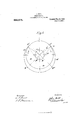
- Figure 1 is a diagram of the said arcs and curves
- Figs. 2 and 3 a plan and elevation respectively, of the instrument for drawing the involute curves.
- one of the involute curves is independthe arc of a circle drawn to the same radius as the drum, 9 g the arc of a circle drawn to the radius of the drum plus the given amount of clearance to be left between the drum a and the arc g 9 and d d the two involute curves, one connecting the end f of one are to the end 9 of the other are, and the other curve connecting the end f of the one are to the end 9 of the other arc.
- the essential feature of the contour produced by the combination of the two circular arcs and two involute curves is that all diametral lines drawn through the center of the axis of the drum from side to side of the casing are equal in length, corresponding to the unvarying length of the piston plate t.
- Fig. 1, 7c is a disk fixed concentrically with the center of the drum
- Z is an unstretchable flexible cord, one end of which is fixed to the disk is at wt preferably with a loop on a pin at that point, the cord is then carried to the left around the disk is to the point f at one end of the circular arcf f and around a pencil or scribing point e placed there, and then back to a pin 19 placed at the center of the drum a to which pin it is attached by a loop or otherwise, so that it is free to turn thereon.
- the clearance is to be about three inches, and that the in volute curve is to subtendone-fourth of the circumference of the drum, twice three inches will be equal to one-fourth of the circumference of the disk 7c; hence the whole circumference of the disk will be approxi mately 2 3 4c equal 24 inches, which will be found slightly too large if it is desired to make the clearance exactly three inches, and in that case the size of the disk must be reduced by trial and error until it is such as will cause the ends 9 g of the involute curves drawn with its assistance to join exactly up to the corresponding ends of the circular are 9 g on the radial lines f g and f 9 respectively. If, however, it is permissible not to make the clearance exactly three inches but only approximately that dimension, it will be sufficient to use the disk made to the is also free to turn on the said pin.
- the whole circumference'wi-ll be approximately equal 16 inches, and a disk of that size can be used in either of theways' above explained in order to draw curves that shall. either terminate so as to give the exact clearance of three inches or one of approximately that dimension, as may he desired.
- k is the disk hereinbefore referred to'whichis fixed on aboard, sheet of paper or other flat material g, (upon which the curves" are to be drawn) concentrically with a circle a; previously drawn on the board 9 and representing the drum (1; of the engine, the contour of the outer casing of'which is required.
- p is a pin standing up at the center of the disk a.
- 1* is abar' or metal or other suitable material having a slot s-which takes over the pin'p, the bar being thereby free to slide longitudinally while being, guided by the pin 1?.
- e and e are pencils" or scribersfixed one at each end of the bar? at a distance apart from point to point exactly equal to the diametral' linef g" or f 9 of Fig. 1.
- Z is a cord one end of which is fixed to the disk 7&- at m. The cord is then carried to the left around the disk 70 to and around the pencil e and thence to the pin 1) on to which the end is looped so as to be free to turn thereon.
- Z is a similar cord one end of which is fixed to the disk k at m, the cord is then carried to the rightaround the disk 7:?
- the pencil 6 will describe on the board g the involutecu-rve (Z and the'pencil ctheinvolute curve 621.
- the penoils e and 6 may be mounted in movable blocks a sliding in slots a so that they can be adjusted to any required distance apart and fixed by set screws w.
- small pulleys y may be mounted rotatably on the pencils around which the cords are passed instead of i around the stationary bodies of the pencils, whereby frictional resistance is reduced.
- the bar 1 may be made doubleended, that is to say, with a pencil at each end, it may be made single-ended, that is with a pencil at one end only, and with one cord; in that case, however, each curve has to be drawn separately, and after one curve is drawn the bar has to be turned the disk is in order to draw the other curve, but I prefer the double-ended arrangement shown in the drawings.
- I claim as my invention 2-- A device for drawing curves comprising a disk, an inextensible cord fixed at one end to a point in the circumference of and passing around said disk, and rotatably attached at the other end to'the center of said disk, and a pencil or scriber in the bend of the cord.
Landscapes
- Toys (AREA)
Description
J. GILL.
CURVE SCRIBER.
APPLIOATIOH FILED JULY 30, 1906'.
Patented May 25,1909;
2 SHEETS-SHEET 2.
1n: nmus Purim ca. wummaau, 0.4:v
FATFLNT FFEQE,
JOHN GI LL, OF EDINBURGH, SCOTLAND.
cuavnscnrenn.
Specification oi. Letters Patent.
Patented Tviay 25, 1909.
Application filed July 30, 1906. Serial No. 328,350.
To all whom it may concern:
Be it known that 1, JOHN GILL, a subject of the King of Great Britain, residing at Edinburgh, Scotland, have invented new and useful Improvements in Curve-Scribers, of which the following is a specification.
This invention relates to an instrument for drawing the involute curves forming part of the internal surface of the outer casing of a rotary engine, pump or the like, of the class in which a cylindrical drum revolves inside an outer casing, and is provided with a sliding plate of unvarying length which passes through the axis of the said drum and forms the piston upon which the motive fluid acts, and in which the inner surface of the outer casing against which the ends of the said piston plate bear, is composed of two circular arcs concentric with the cylindrical drum the ends of which arcs are connected together by two involute curves as shown in. the accompanying drawings, in which Figure 1 is a diagram of the said arcs and curves, and Figs. 2 and 3 a plan and elevation respectively, of the instrument for drawing the involute curves.
(t represents the said cylindrical drum, f f
one of the involute curves; but is independthe arc of a circle drawn to the same radius as the drum, 9 g the arc of a circle drawn to the radius of the drum plus the given amount of clearance to be left between the drum a and the arc g 9 and d d the two involute curves, one connecting the end f of one are to the end 9 of the other are, and the other curve connecting the end f of the one are to the end 9 of the other arc. The essential feature of the contour produced by the combination of the two circular arcs and two involute curves is that all diametral lines drawn through the center of the axis of the drum from side to side of the casing are equal in length, corresponding to the unvarying length of the piston plate t. It is for the drawing of these two involute curves f g and f 9 that the instrument forming the subject of the present invention has been devised. This instrument is of the following character: Referring more particularly to Fig. 1, 7c is a disk fixed concentrically with the center of the drum 0, Z is an unstretchable flexible cord, one end of which is fixed to the disk is at wt preferably with a loop on a pin at that point, the cord is then carried to the left around the disk is to the point f at one end of the circular arcf f and around a pencil or scribing point e placed there, and then back to a pin 19 placed at the center of the drum a to which pin it is attached by a loop or otherwise, so that it is free to turn thereon. By now moving the pencil or scriber 6, While keeping the cord Z taut, around from the point f in the direction of the plain arrow to the point g at one end of the circular arc g 9 the cord unwinds from the disk 75 and slips, to a certain extent, around the pencil or scriber c and the proper curve (Z for that side of the casing is thus described. in order to describe the curve (Z for the opposite side of the casing it is only necessary to wind the cord Z around the disk is in the opposite direction and around the pencil or scriber e placed at f and to move the pencil in the direction of the feathered arrow from the point f at the opposite end of the circular arc f f to the point g at the end of the circular arc g 9 The circumference of the disk 74 to be used in the above described device for drawing the involute curves is dependent upon two factors, namely :the radial distance between the drum a and the are 9 g (which distance may be conveniently called the clearance), and the fraction of the whole circumference of the drum or subtended by ent of the size of the drum; and the rule for finding approximately the circumference of the disk from these data is that twice the clearance in inches is approximately equal to the fraction of the circumference in inches of the disk that corresponds to the fraction of the circumference of the drum subtended by one of the involute curves. For example, assuming the clearance is to be about three inches, and that the in volute curve is to subtendone-fourth of the circumference of the drum, twice three inches will be equal to one-fourth of the circumference of the disk 7c; hence the whole circumference of the disk will be approxi mately 2 3 4c equal 24 inches, which will be found slightly too large if it is desired to make the clearance exactly three inches, and in that case the size of the disk must be reduced by trial and error until it is such as will cause the ends 9 g of the involute curves drawn with its assistance to join exactly up to the corresponding ends of the circular are 9 g on the radial lines f g and f 9 respectively. If, however, it is permissible not to make the clearance exactly three inches but only approximately that dimension, it will be sufficient to use the disk made to the is also free to turn on the said pin.
above size and to draw the involutecurves by its means, the result of which will be that the ends 9 g of those curves will cut the radial lines f g and f g at points slightly more than three inches from the drum (1, and
then, instead of drawing the are 9- g at the three-eighths of the circumference of the disk, the whole circumference'wi-ll be approximately equal 16 inches, and a disk of that size can be used in either of theways' above explained in order to draw curves that shall. either terminate so as to give the exact clearance of three inches or one of approximately that dimension, as may he desired.
A convenient arrangement of the instrument which forms the subject of the present invention is shown in Figs. 2 and 3, in which k is the disk hereinbefore referred to'whichis fixed on aboard, sheet of paper or other flat material g, (upon which the curves" are to be drawn) concentrically with a circle a; previously drawn on the board 9 and representing the drum (1; of the engine, the contour of the outer casing of'which is required. p is a pin standing up at the center of the disk a. 1* is abar' or metal or other suitable material having a slot s-which takes over the pin'p, the bar being thereby free to slide longitudinally while being, guided by the pin 1?. e and e are pencils" or scribersfixed one at each end of the bar? at a distance apart from point to point exactly equal to the diametral' linef g" or f 9 of Fig. 1. Z is a cord one end of which is fixed to the disk 7&- at m. The cord is then carried to the left around the disk 70 to and around the pencil e and thence to the pin 1) on to which the end is looped so as to be free to turn thereon. Z is a similar cord one end of which is fixed to the disk k at m, the cord is then carried to the rightaround the disk 7:? to and around the pencil c and thence to the pin 1) on to which theend is looped so that it It will now be understood that on turning the'b'ar 7" around in a horizontal plane on the pin 1), say I in the direction of the arrow in Fig. 2, the cord Z will unwind from the disk 7c while the cord Z will wind on to it, the result being that the bar 1" is caused to slide on the pin 1) 1n the direction from c to e. On the contrary if the bar 1 is turned in the oppositedi-rection the cord Z is wound on to the disk is and the cord Z is unwound therefrom, with the result that the bar is caused to slide in the direction from 6 to e It now the bar 1" is placed so that the pencil e coincides with the point f, and the pencil c with the point 9, and the bar is turned in the direction of the arrow,
the pencil 6 will describe on the board g the involutecu-rve (Z and the'pencil ctheinvolute curve 621.
In order to adapt the instrument for draw ing the involute curve for drums a of various diameters and various clearances, the penoils e and 6 may be mounted in movable blocks a sliding in slots a so that they can be adjusted to any required distance apart and fixed by set screws w.
To tacilitate the movement of the cords Z and 1 around the pencils 6 and 6 small pulleys y may be mounted rotatably on the pencils around which the cords are passed instead of i around the stationary bodies of the pencils, whereby frictional resistance is reduced.
Instead of the bar 1 being made doubleended, that is to say, with a pencil at each end, it may be made single-ended, that is with a pencil at one end only, and with one cord; in that case, however, each curve has to be drawn separately, and after one curve is drawn the bar has to be turned the disk is in order to draw the other curve, but I prefer the double-ended arrangement shown in the drawings.
I claim as my invention 2-- A device for drawing curves comprising a disk, an inextensible cord fixed at one end to a point in the circumference of and passing around said disk, and rotatably attached at the other end to'the center of said disk, and a pencil or scriber in the bend of the cord.
In testimony whereof I have signed my name to this specification in the'presenc'e of two subscribing witnesses.
JOHN GILL.
Witnesses:
JAMES GILL, I D'AVID GALLowAY Annnnson;
.to the other side and the cord reversed on V
Priority Applications (1)
| Application Number | Priority Date | Filing Date | Title |
|---|---|---|---|
| US32835006A US922575A (en) | 1906-07-30 | 1906-07-30 | Curve-scriber. |
Applications Claiming Priority (1)
| Application Number | Priority Date | Filing Date | Title |
|---|---|---|---|
| US32835006A US922575A (en) | 1906-07-30 | 1906-07-30 | Curve-scriber. |
Publications (1)
| Publication Number | Publication Date |
|---|---|
| US922575A true US922575A (en) | 1909-05-25 |
Family
ID=2991007
Family Applications (1)
| Application Number | Title | Priority Date | Filing Date |
|---|---|---|---|
| US32835006A Expired - Lifetime US922575A (en) | 1906-07-30 | 1906-07-30 | Curve-scriber. |
Country Status (1)
| Country | Link |
|---|---|
| US (1) | US922575A (en) |
-
1906
- 1906-07-30 US US32835006A patent/US922575A/en not_active Expired - Lifetime
Similar Documents
| Publication | Publication Date | Title |
|---|---|---|
| US922575A (en) | Curve-scriber. | |
| US841223A (en) | Drawing apparatus. | |
| US1326696A (en) | Involutb-citrve-generating machine | |
| US1109479A (en) | Measuring instrument. | |
| US678005A (en) | Folding rule. | |
| US1289047A (en) | Combined rule and square. | |
| US467825A (en) | Drawing-board | |
| US548327A (en) | District of | |
| US281619A (en) | cbowell | |
| US652411A (en) | Index for mechanical account apparatus. | |
| US639488A (en) | Compass for drawing conic sections. | |
| US1022969A (en) | Ellipsograph. | |
| US587940A (en) | Hand-measurer for gloves | |
| US36936A (en) | Improved steering apparatus | |
| US246663A (en) | Pantograph | |
| US1095317A (en) | Mechanism for delineating cross-section contours. | |
| US77305A (en) | Improvement in apparatus for measuring oloth | |
| US1026123A (en) | Calculator. | |
| US282831A (en) | Frank aborn | |
| US1148122A (en) | Drawing instrument. | |
| US853262A (en) | Computing-calipers. | |
| US528476A (en) | Ruling device | |
| US504286A (en) | Dynamometer | |
| US1056821A (en) | Note-sheet-guiding device. | |
| US495175A (en) | Edgar j |