US9219066B2 - Method of manufacturing semiconductor storage device and semiconductor storage device - Google Patents
Method of manufacturing semiconductor storage device and semiconductor storage device Download PDFInfo
- Publication number
- US9219066B2 US9219066B2 US13/847,107 US201313847107A US9219066B2 US 9219066 B2 US9219066 B2 US 9219066B2 US 201313847107 A US201313847107 A US 201313847107A US 9219066 B2 US9219066 B2 US 9219066B2
- Authority
- US
- United States
- Prior art keywords
- film
- insulating film
- gate electrode
- memory
- region
- Prior art date
- Legal status (The legal status is an assumption and is not a legal conclusion. Google has not performed a legal analysis and makes no representation as to the accuracy of the status listed.)
- Active, expires
Links
Images


Classifications
-
- H01L27/1052—
-
- H01L21/764—
-
- H01L21/7682—
-
- H01L21/76837—
-
- H01L27/11524—
-
- H—ELECTRICITY
- H10—SEMICONDUCTOR DEVICES; ELECTRIC SOLID-STATE DEVICES NOT OTHERWISE PROVIDED FOR
- H10B—ELECTRONIC MEMORY DEVICES
- H10B41/00—Electrically erasable-and-programmable ROM [EEPROM] devices comprising floating gates
- H10B41/30—Electrically erasable-and-programmable ROM [EEPROM] devices comprising floating gates characterised by the memory core region
- H10B41/35—Electrically erasable-and-programmable ROM [EEPROM] devices comprising floating gates characterised by the memory core region with a cell select transistor, e.g. NAND
-
- H—ELECTRICITY
- H10—SEMICONDUCTOR DEVICES; ELECTRIC SOLID-STATE DEVICES NOT OTHERWISE PROVIDED FOR
- H10W—GENERIC PACKAGES, INTERCONNECTIONS, CONNECTORS OR OTHER CONSTRUCTIONAL DETAILS OF DEVICES COVERED BY CLASS H10
- H10W10/00—Isolation regions in semiconductor bodies between components of integrated devices
- H10W10/01—Manufacture or treatment
- H10W10/021—Manufacture or treatment of air gaps
-
- H—ELECTRICITY
- H10—SEMICONDUCTOR DEVICES; ELECTRIC SOLID-STATE DEVICES NOT OTHERWISE PROVIDED FOR
- H10W—GENERIC PACKAGES, INTERCONNECTIONS, CONNECTORS OR OTHER CONSTRUCTIONAL DETAILS OF DEVICES COVERED BY CLASS H10
- H10W10/00—Isolation regions in semiconductor bodies between components of integrated devices
- H10W10/20—Air gaps
-
- H—ELECTRICITY
- H10—SEMICONDUCTOR DEVICES; ELECTRIC SOLID-STATE DEVICES NOT OTHERWISE PROVIDED FOR
- H10W—GENERIC PACKAGES, INTERCONNECTIONS, CONNECTORS OR OTHER CONSTRUCTIONAL DETAILS OF DEVICES COVERED BY CLASS H10
- H10W20/00—Interconnections in chips, wafers or substrates
- H10W20/01—Manufacture or treatment
- H10W20/071—Manufacture or treatment of dielectric parts thereof
- H10W20/072—Manufacture or treatment of dielectric parts thereof of dielectric parts comprising air gaps
-
- H—ELECTRICITY
- H10—SEMICONDUCTOR DEVICES; ELECTRIC SOLID-STATE DEVICES NOT OTHERWISE PROVIDED FOR
- H10W—GENERIC PACKAGES, INTERCONNECTIONS, CONNECTORS OR OTHER CONSTRUCTIONAL DETAILS OF DEVICES COVERED BY CLASS H10
- H10W20/00—Interconnections in chips, wafers or substrates
- H10W20/01—Manufacture or treatment
- H10W20/071—Manufacture or treatment of dielectric parts thereof
- H10W20/098—Manufacture or treatment of dielectric parts thereof by filling between adjacent conductive parts
-
- H—ELECTRICITY
- H10—SEMICONDUCTOR DEVICES; ELECTRIC SOLID-STATE DEVICES NOT OTHERWISE PROVIDED FOR
- H10W—GENERIC PACKAGES, INTERCONNECTIONS, CONNECTORS OR OTHER CONSTRUCTIONAL DETAILS OF DEVICES COVERED BY CLASS H10
- H10W20/00—Interconnections in chips, wafers or substrates
- H10W20/40—Interconnections external to wafers or substrates, e.g. back-end-of-line [BEOL] metallisations or vias connecting to gate electrodes
- H10W20/45—Interconnections external to wafers or substrates, e.g. back-end-of-line [BEOL] metallisations or vias connecting to gate electrodes characterised by their insulating parts
- H10W20/46—Interconnections external to wafers or substrates, e.g. back-end-of-line [BEOL] metallisations or vias connecting to gate electrodes characterised by their insulating parts comprising air gaps
Definitions
- Embodiments disclosed herein generally relate to a method of manufacturing semiconductor storage device and a semiconductor storage device.
- NAND flash memory Semiconductor storage device such as a NAND flash memory is facing increasing demand for further microfabrication.
- Narrower gate width and gate length of the memory cell requires smaller spacing between the adjacent memory-cell gate electrodes and thereby increases parasitic capacitance of the memory-cell gate electrodes to an unignorable level.
- the memory cells are typically isolated by providing an element isolation region between the adjacent memory cells and filling the element isolation region with an insulating film. However the relative dielectric constant of the fill insulating film is greater than 1.
- One approach for reducing capacitive coupling is providing an air gap in the element isolation region.
- a typical air gap formation in the element isolation region includes formation of an insulating film to enclose the air gaps.
- formation of the insulating film after the formation of the air gap may cause refilling of the air gaps by the insulating film.
- an element isolation region mostly configured by an air gap exhibits good electric properties but is not as strong as an element isolation region filled with an insulation film.
- FIG. 1 pertains to a first embodiment and illustrates one schematic example of a partial equivalent circuit representation of a semiconductor storage device.
- FIG. 2 pertains to the first embodiment and partially illustrates one schematic example of a planar layout of the semiconductor storage device.
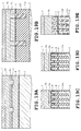
- FIGS. 3A , 3 B, 3 C, 3 D, and 3 E pertain to the first embodiment and each illustrate a schematic example of a vertical cross-sectional view taken along lines A-A, B-B, C-C, D-D, and E-E of FIG. 2 , respectively.
- FIG. 4A pertains to the first embodiment and is one schematic example of a perspective view illustrating air gaps formed between word lines and air gaps formed in element isolation trench.
- FIG. 4B pertains to the first embodiment and is one schematic example of a perspective view illustrating the structure of a boundary wall of an air gap located below a select gate line.
- FIG. 5A-FIG . 5 E to FIG. 25A-FIG . 25 E pertain to the first embodiment and each illustrate one schematic example of a vertical cross sectional view of one phase of the manufacturing process flow.
- FIGS. 26A to 26E pertain to a second embodiment and each illustrate a schematic example of a vertical cross-sectional view corresponding to FIGS. 3A to 3E .
- FIG. 27 pertains to the second embodiment and is one schematic example of a perspective view corresponding to FIG. 4B .
- FIGS. 28A-28E to FIGS. 45A-45E pertain to the second embodiment and each illustrate one schematic example of a vertical cross sectional view of one phase of the manufacturing process flow.
- a method of manufacturing a semiconductor storage device includes forming a first gate insulating film and a first gate electrode film in the listed sequence above a first region and a second region of a semiconductor substrate; forming an element isolation trench along a first direction into the first gate electrode film, the first gate insulating film, and an upper portion of the semiconductor substrate to define a plurality of element regions extending in the first direction and being isolated from one another in a second direction intersecting with the first direction; filling the element isolation trench with a sacrificial film; forming an interelectrode insulating film along the first gate electrode film and the sacrificial film; forming a second gate electrode film above the interelectrode insulating film; forming, in the first region, a first trench extending through the second gate electrode film and the interelectrode insulating film, and a second trench extending through the second gate electrode film and the interelectrode insulating film and extending partially into the sacrificial film
- FIGS. 1 to 25E A first embodiment is described hereinafter through a NAND flash memory application with references to FIGS. 1 to 25E .
- the drawings are not drawn to scale and thus, do not reflect the actual measurements of the features such as the correlation of thickness to planar dimensions and the relative thickness of different layers.
- directional terms such as up, upper, upward, down, lower, downward, left, leftward, right, and rightward are used in a relative context with an assumption that the worked surface of the later described semiconductor substrate faces up. Thus, the directional terms do not necessarily correspond to the directions based on gravitational acceleration.
- FIG. 1 is one example of a partial equivalent circuit representation of a memory cell array located in a memory cell region of NAND flash memory 1 .
- the memory cell array includes multiplicity of units of cells also referred to as NAND cell unit SU or a NAND string arranged in rows and columns.
- NAND cell unit SU comprises a multiplicity of series connected memory cell transistors Trm, such as 64 in number, situated between a couple of select transistors Trs 1 and Trs 2 that are located at Y-direction ends of NAND cell unit SU.
- the neighboring memory cell transistors Trm within NAND cell unit SU share their source/drain regions.
- the X-direction aligned memory cell transistors Trm shown in FIG. 1 are interconnected by common word line WL extending in the X direction, whereas the X-direction aligned select transistors Trs 1 are interconnected by common select gate line SGL 1 extending in the X direction and likewise, the X-direction aligned select transistors Trs 2 are interconnected by common select gate line SGL 2 also extending in the X direction.
- each select transistor Trs 1 located on one end of NAND cell unit SU is coupled to bit line BL by way of bit line contact CB shown in FIG. 1 .
- Bit line BL extends in the Y direction orthogonal to the X direction shown in FIG. 1 .
- the source of each select transistor Trs 2 located on the other end of NAND cell unit SU is coupled to source line SL extending in the X-direction.
- FIG. 2 partially illustrates one example of a planar layout of the memory cell region.
- multiplicity of element isolation regions Sb run in the Y direction as viewed in FIG. 2 of a p-type silicon substrate 2 , or more generally, a semiconductor substrate 2 .
- Element isolation regions Sb are separated from one another in the X direction as viewed in FIG. 2 to isolate element regions Sa, running in the Y-direction, by a predetermined space interval in the X direction.
- the isolation employs a shallow trench isolation scheme known as STI.
- Multiplicity of word lines WL spaced from one another in the Y direction by a predetermined spacing, extend in the X direction as viewed in FIG. 2 which is the direction orthogonal to the Y direction in which element region Sa extends.
- gate electrode MG of memory cell transistor Trm shown in FIG. 3A is formed above element region Sa intersecting with word line WL.
- Gate electrode MG is also referred to as a second gate electrode.
- Y-directionally adjacent memory cell transistors Trm are situated between a couple of select transistors Trs 1 and Trs 2 that are located at Y-direction ends of NAND cell unit SU as shown in FIG. 1 .
- Multiplicity of select transistors Trs 1 are aligned in the X direction and are electrically interconnected by a common select gate line SGL 1 as described earlier.
- Select gate electrode SG shown in FIGS. 2 and 3 also referred to as a first gate electrode is formed above element region Sa intersecting with select gate line SGL 1 .
- multiplicity of select transistors Trs 2 are aligned in the X direction and are interconnected by a common select gate line SGL 2 as described earlier.
- select gate electrode SG also referred to as a first gate electrode is formed above element region Sa intersecting with select gate line SGL 2 .
- the select gate electrodes of select transistors are electrically interconnected by select gate line SGL 2 .
- bit line contact CB is formed in each element isolation region Sa located between select transistors Trs 1 of Y-directionally adjacent NAND cell units SU. As shown in FIG. 1 each of the Y-directionally adjacent NAND cell unit SU belongs to a different block, namely block B k and block B k+1 . Though not shown, a source line contact is formed in element region Sa located between a pair of select gate lines SGL 2 .
- element region Sa extending along line 3 A- 3 A of FIG. 2 will also be referred to as first element region Sa 1 and the element region which is X-directionally adjacent to first element region Sa 1 over element isolation region Sb is referred to as second element region Sat as required.
- a group of memory-cell gate electrodes MG located above first element region Sa 1 may also be referred to as first memory-cell gate electrode group MG 1
- a group of memory-cell gate electrodes MG located above second element region Sa 2 may also be referred to as second memory-cell gate electrode group MG 2 .
- the group of memory cell transistors Trm in which first memory-cell gate electrode group MG 1 serves as the gate electrode is also referred to as memory-cell transistor group Trm 1
- the group of memory cell transistors Trm in which first memory-cell gate electrode group MG 2 serves as the gate electrode is also referred to as memory-cell transistor group Trm 2 .
- memory-cell transistor group Trm 1 and memory-cell transistor group Trm 2 are X-directionally adjacent to one another.
- FIG. 3A illustrates one example of a Y-direction cross sectional structure of a opposing pair of select gate transistor Trs 1 as well as bit line contact CB located between the opposing select gate transistors Trs 1 .
- gate insulating film 3 is formed above semiconductor substrate 2 , which may, in one embodiment, be a p-type silicon substrate 2 .
- First gate insulating film 3 may comprise a silicon oxide film, for example, and is formed above semiconductor substrate 2 .
- First gate insulating film 3 is absent from the region of semiconductor substrate where bit line contact CB is located.
- First gate insulating film 3 located above first element region Sa 1 is referred to as a first surface-layer gate insulating film and gate insulating film 3 above second element region Sa 2 is referred to as a second surface-layer gate insulating film.
- Memory cell transistor Trm includes memory-cell gate electrode MG formed above gate insulating film 3 and source/drain region 2 a.
- Memory-cell gate electrode MG includes floating gate electrode FG, interelectrode insulating film 5 , and control gate electrode CG stacked in the listed sequence.
- Floating gate electrode FG comprises polysilicon film 4 also referred to as a first gate electrode film doped with impurities.
- Source/drain region 2 a is formed in the surface layer of semiconductor substrate 2 located beside the stacked gate electrode MG.
- Interelectrode insulating film 5 is an intergate insulating film located between floating gate electrode FG and control gate electrode CG and may also be referred to as an interpoly insulating film and inter-conductive-layer insulating film.
- Interelectrode insulating film 5 may take an ONO structure comprising a stack of oxide/nitride/oxide films, which may be provided with additional bottom and top nitrides to take a NONON structure. Further, the middle nitride film may be replaced by a high dielectric constant insulating film such as alumina or hafnium oxide.
- Control gate electrode CG comprises polysilicon film 6 a and polysilicon film 6 b stacked in the listed sequence.
- the upper portion of polysilicon film 6 b is silicided by metal to reduce the resistivity of control gate electrode CG.
- control gate electrode CG comprises a stack of polysilicon layer 6 a , polysilicon layer 6 b , and silicide layer 7 .
- Metal such as tungsten (W) may be used in the silicidation.
- the upper portion of polysilicon film 6 a may also be silicided.
- FIG. 3A shows a string of memory cell transistors Trm aligned in the Y direction and select transistor Trs 1 at the end of the string.
- select gate electrode SG of select transistor Trm is substantially identical in structure to memory-cell gate electrode MG of memory cell transistor Trm and comprises polysilicon film 4 , interelectrode film 5 , polysilicon films 6 a and 6 b , and silicide layer 7 in the upper portion of polysilicon film 6 a.
- Select gate electrode SG differs from memory-cell gate electrode MG in that a through hole penetrates the central portion of interelectrode insulating film 5 to establish physical contact between polysilicon film 4 and polysilicon film 6 b .
- Select gate electrode of select gate transistor Trs 2 is structured in the same manner though a cross sectional view is not given.
- an air gap or an unfilled gap represented by AG is provided between memory-cell gate electrodes MG. Provision of air gap AG suppresses the coupling capacitance between the adjacent memory-cell gate electrodes MG. Air gap AG is further provided between memory-cell gate electrode MG and select gate electrode SG. Though not shown, protective film comprising an oxide film is formed along the sidewalls of memory-cell gate electrode MG and select gate electrode SG.
- silicon nitride film 8 and TEOS (tetraethyl orthosilicate) film 9 are stacked in the listed sequence.
- Silicon nitride film 8 serves as a cap film.
- silicon oxide film 10 serving as an interlayer insulating film is formed which extends across air gaps AG defined between gate electrodes MG and between gate electrodes MG and SG.
- silicon oxide film 11 is formed along the sidewall of select gate electrode SG facing the opposing select gate electrode SG.
- Silicon oxide film 11 serves as a spacer insulating film for forming a deep and heavily doped diffusion layer 2 b into a surface layer of semiconductor substrate 2 located in the inner side of silicon oxide film 11 where bit line contact CB is to be formed.
- silicon oxide film 12 is formed which further extends along the upper surface and sidewall of silicon oxide film 10 , the upper surface and sidewall of TEOS film 9 , and the sidewall of silicon nitride film 8 .
- interlayer insulating film 13 comprising a silicon oxide film is formed so as to fill the gap between select gate electrodes SG.
- a through hole that extends into diffusion layer 2 b of semiconductor substrate 2 is formed through interlayer insulating film 13 and silicon oxide film 12 .
- the inner side of the through hole is lined with a barrier metal and filled with materials such as tungsten (W).
- FIG. 4A primarily illustrates examples of air gaps AG located between Y-directionally adjacent word lines WL, in other words, Y-directionally adjacent memory-cell gate electrodes MG as well as air gaps AG located between X-directionally adjacent element regions Sa.
- FIG. 4B primarily illustrates air gaps AG located between Y-directionally adjacent select gate line SGL 1 and word line WL.
- element isolation region Sb comprises silicon oxide film 14 filled along the bottom surface of element isolation trench Sb 1 and TEOS film 15 formed above silicon oxide film 14 .
- Silicon oxide film 14 serves as the bottom surface of air gap AG whereas TEOS film 15 serves as the sidewall of air gap AG.
- the depth of air gap AG in element isolation region Sb is controlled to be equal to or greater than 1 ⁇ 2 of the Y-directional width of select gate electrode SG to thereby improve the performance of element isolation.
- select gate electrode SG is formed above element region Sa. It can be understood from further reference to FIG. 3B that select gate electrodes SG are interconnected by select gate line SGL 1 extending in the X direction, in other words, in the direction normal to the page of FIG. 3E .
- select gate line SGL 1 comprises a stack of polysilicon 6 a , 6 b , and silicide film 7 .
- TEOS film 15 comprising a silicon oxide film is formed immediately below select gate line SGL 1 and air gap AG is formed on the word line WL side of TEOS film 15 .
- air gap AG is provided in element isolation region Sb formed between element regions Sa and is located below word line WL.
- the portion of element isolation region Sb running between select gate lines SGL 1 is enclosed by TEOS film 15 and filled with silicon oxide film 12 .
- TEOS film 15 serves as a stopper or a wall to withhold silicon oxide film 12 .
- air gap AG is not provided in the portion of element isolation region Sb running between select gate lines SGL 1 .
- the gases for forming silicon oxide film 12 flows into element isolation region Sb through the gap between select gate line SGL 1 of block B k+1 and select gate line SGL 1 of block B k .
- silicon oxide film 12 is formed between TEOS film 15 located immediately below select gate line SGL 1 of block B k+1 and TEOS film 15 located immediately below select gate line SGL 1 of block B k .
- TEOS film 15 extends across element region Sa located immediately below select gate line SGL 1 of block B k+1 and element region Sa select gate line SGL 1 of block B k thus, the formation of silicon oxide film 12 is blocked by TEOS film 15 .
- a gate insulating film 3 is formed above semiconductor substrate 2 .
- semiconductor substrate comprises a p-type silicon substrate and thus, a silicon oxide film is formed by thermal oxidation to obtain gate insulating film 3 also referred to as first/second gate insulating film depending upon location.
- Polycrystalline silicon film 4 later formed into floating gate electrode is deposited above gate insulating film 3 by LPCVD (Low Pressure Chemical Vapor Deposition).
- Polycrystalline silicon film 4 is doped with n-type impurities such as phosphorous (P).
- Silicon nitride film 16 is deposited in appropriate thickness above polycrystalline silicon film 4 .
- oxide film 17 serving as a hard mask is deposited in appropriate thickness.
- Resist 18 is further coated over oxide film 17 .
- resist 18 is exposed and thereafter developed into a line and space pattern of a predetermined pitch.
- oxide film 17 is anisotropically etched to define element isolation trench Sb 1 isolated in the X direction. Resist 18 is removed after the etching.
- silicon nitride film 16 is anisotripically etched by RIE.
- Polycrystalline silicon film 4 , gate insulating film 3 , and the upper portion of silicon substrate 2 is further anisotropically etched by a predetermined pitch to form element isolation trench Sb 1 .
- element isolation trench Sb 1 is filled with a polysilazane 14 a coating liquid.
- Polysilzazane 14 a is an organic compound having a molecular structure of (SiH 2 —NH).
- Polysilazane 14 a is planarized by CMP (Chemical Mechanical Polishing) until the upper surface of silicon nitride film 16 is exposed.
- the upper surface of polysilazane 14 a is selectively etched back.
- the duration of etching is controlled such that the upper surface of polysilazane 14 a is substantially level with the interface between polysilicon film 4 and silicon nitride film 16 .
- Silicon nitride film 16 remaining above polysilicon film 4 is selectively removed, for instance, by wet etching.
- polysilicon film 4 serving as the first gate electrode film becomes substantially level with polysilazane 14 a serving as a sacrificial film.
- the upper surface of polysilazane 14 a is selectively etched back so as to be lower than the upper surface of polysilicon film 4 but higher than the upper surface of gate insulating film 3 .
- interelectrode insulating film 5 is formed above the upper surface of polycrystalline silicon film 4 by deposition of films such as an ONO (Oxide-Nitride-Oxide) film by LPCVD.
- NONON film may be employed instead of the ONO film which may be obtained by radically nitriding the lowermost oxide film and the uppermost oxide film of the ONO film.
- the middle nitride film of the ONO film may be replaced by a high dielectric constant film such a aluminum oxide also referred to as alumina.
- first polycrystalline silicon film 6 a serving as the second gate electrode film is deposited by CVD.
- region R of polysilicon film 6 a is processed by lithography and anisotropic etching. Region R is located substantially on a Y-directional center of region SGL 1 _FR where select gate line SGL 1 is to be formed. Region R is a region for establishing contact between polysilicon film 4 and polysilicon film 6 b . As shown in FIGS. 13A to 13E , polysilicon film 6 a deposited above interelectrode insulating film 5 is removed to define an opening without etching interelectrode insulating film 5 serving as an etch stop.
- interelectrode insulating film 5 and polysilazane 14 a is etched back using polysilicon film 6 a as a mask to deepen the opening into a trench.
- the etch back may be achieved through RIE and then wet etching using buffered hydrogen fluoride solution as a wet etchant. In an alternative embodiment, the wet etching may be omitted.
- Polysilazane 14 a is etched with selectivity to polysilicon film 4 and thus, the depth of etching of polysilazane 14 a shown in FIG. 15B is greater than the depth of etching of polysilicon film 4 .
- the trenches formed by the etch back is overfilled with TEOS film 15 deposited by LP-CVD.
- the overfilled TEOS film 15 is etched back. As shown in FIG. 17B , the duration of the etching is controlled such that TEOS film 15 in the trench is substantially level with the upper surface of interelectrode insulating film 5 .
- polysilicon film 6 b serving as the third gate electrode film is formed above polysilicon film 4 and polysilicon film 6 a by LP-CVD.
- metal such as tungsten (W) is sputtered above polysilicon film 6 b and thermally treated to obtain silicide layer 7 .
- silicon nitride film 8 and TEOS film 9 serving as masks are deposited in the listed sequence by LP-CVD. Using lithography and anisotropic etching, TEOS film 9 , silicon nitride film 8 , silicide layer 7 , polysilicon films 6 a and 6 b , interelectrode insulating film 5 and polysilicon film 4 are etched. First gate insulating film 3 may be etched at this phase of the manufacturing process flow.
- Memory-cell gate electrodes MG collectively referred to as word line WL and select gate electrodes SG collectively referred to as select gate line SGL 1 are formed by the foregoing manufacturing process flow.
- films 4 , 5 , 6 a , 6 b , 7 , 8 , and 9 are removed to expose the upper surface and upper sidewall of polysilazane 14 a.
- hydrogen-fluoride based wet etchant is used to remove polysilazane 14 a exposed by the gate structure formation to a predetermined depth.
- the wet etching of polysilazane 14 a serving as a sacrificial film, is controlled to a lower wet etching rate as compared to the wet etching rate of TEOS film 15 .
- the region where polysilazane 14 a is removed serves as air gap AG which occupies most of element isolation region Sb.
- FIG. 21C the regions located below interelectrode insulating film 5 and located between element regions Sa where polysilazane 14 a is removed constitutes air gap AG.
- silicon oxide film 10 is deposited by plasma CVD so as to cover the isolated memory-cell gate electrodes MG and select gate electrodes SG.
- Plasma CVD provides relatively poor step coverage and thus poor gap fill capability as compared to an ordinary CVD method.
- Silicon oxide film 10 is deposited over across TEOS film 9 located above word lines WL and TEOS film 9 located above select gate lines SGL 1 . As a result, air gap AG is formed between memory-cell gate electrodes MG and between memory-cell gate electrodes MG and select gate electrodes SG.
- silicon oxide film 10 is formed so as to enclose gap AG 1 of element isolation region Sb and across element regions Sa.
- a mask pattern not shown is formed for defining an opening in the region between select gate electrodes SGL 1 by lithography.
- silicon oxide film 10 located between select gate electrodes SGL 1 is formed into a spacer by anisotropic etching.
- Silicon oxide film 10 formed into a spacer is represented as silicon oxide film 11 in FIGS. 23A and 23B , 24 A and 24 B, and 25 A and 25 B.
- silicon oxide film 12 is deposited by LP-CVD.
- TEOS film 15 is formed below select gate line SGL 1 so as to serve as a boundary wall of air gap AG prior to the formation of silicon oxide film 12 .
- the intrusion of gas used in forming silicon oxide film 12 into element isolation trench Sb 1 located below word line WL can be suppressed.
- silicon oxide film 12 is formed in the portion in element isolation trench Sb 1 located between TEOS film 15 below select gate lines SGL 1 , in other words, in gap AG 1 .
- a silicon nitride film not shown serving as a CMP stopper is deposited by LP-CVD and as shown in FIGS. 25A to 25E , interlayer insulating film 13 comprising a BSPSG film is further deposited so as to reside in the inner side of the silicon nitride film.
- interlayer insulating film 13 planarization is carried out by CMP, whereafter additional interlayer insulating film not shown is further deposited above interlayer insulating film 13 .
- a contact hole for forming bit line contact CB is formed through interlayer insulating film 13 .
- NAND flash memory 1 is obtained by the above described embodiments.
- polysilazane 14 a is coated into the region for forming element isolation region Sb as a sacrificial film and polysilazane 14 a is removed after depositing layers of films in order to provide air gap AG in element isolation region Sb. If only the above described process flow is considered, element isolation region Sb may become refilled by the intrusion of gases into the region where polysilazane 14 a was removed in the subsequent formation of other functional films. Hence, it may not be possible to provide air gap AG in element isolation region Sb of the final structure.
- TEOS film 15 is configured to enclose element isolation trench Sb 1 located between first element region Sa 1 below first gate electrode SG 1 and second element region Sa 2 below second gate electrode SG 2 as shown in FIG. 2 .
- air gap AG can be provided reliably in element isolation region Sb located between element region Sa 1 below memory-cell gate electrode group MG 1 and element region Sa 2 below memory-cell gate electrode group MG 2 .
- TEOS film 15 is configured to enclose element isolation regions Sb 1 located below first element region Sa 1 and second element regions Sa 2 immediately below first gate electrode SG 1 in each of blocks B k and B k+1 .
- silicon oxide film 10 is formed into a spacer later in the process flow to define an opening in silicon oxide film 10 located between select gate lines SGL 1 to allow intrusion of gas used in the formation of silicon oxide film 12 below the surface of silicon substrate 2 through the opening, TEOS film 15 formed across element regions Sa 1 and Sa 2 blocks further intrusion of the gas.
- TEOS film 15 suppresses the intrusion of gases such as the ingredient gas for formation of silicon oxide film 12 into air gap AG located between element region Sa 1 below memory-cell gate electrode group MG 1 and element region Sa 2 below memory-cell gate electrode group MG 2 .
- gases such as the ingredient gas for formation of silicon oxide film 12 into air gap AG located between element region Sa 1 below memory-cell gate electrode group MG 1 and element region Sa 2 below memory-cell gate electrode group MG 2 .
- the above described configuration reliably prevents the refilling of air gap AG between element region Sa 1 and element region Sa 2 .
- FIG. 26A to FIG. 45E illustrate a second embodiment.
- the second embodiment described hereinafter includes the following differences from those described above.
- the upper sidewall as well as the upper surface of the first gate electrode film is exposed in the region for forming groups of memory-cell gate electrodes, and when forming the interelectrode insulating film, the topography of the region for forming the select gate electrode is configured such that the upper surface of the sacrificial film is substantially level or coplanar with the upper surface of the first gate electrode film.
- the polysilazane used as a material for forming the sacrificial film is transformed while being exposed to the ambient so that at least a portion of the boundary wall of the air gap is made of an oxide film.
- FIGS. 26A to 26E are schematic examples of cross sectional structures of the second embodiment and corresponds to FIGS. 3A to 3E .
- FIG. 27 is one example of a perspective view corresponding to FIG. 4B .
- silicon oxide film 14 and TEOS oxide film 15 are configured as an air gap wall in element isolation trench Sb 1 located below select gate line SGL 1 .
- the air gap wall is also referred to as a boundary wall, an insulation wall, or simply as a wall serving as a boundary of the air gap.
- Silicon oxide film 14 is formed based on polysilazane 14 a which is hardened by thermal treatment, etc. Silicon oxide film 14 covers the sidewall and the underside of TEOS film 15 .
- the elevation of interelectrode insulating film 5 in the region for forming select gate line SGL 1 is higher as compared to the elevation of interelectrode insulating film 5 in the region for forming word line WL.
- silicon oxide film 14 is formed below interelectrode insulating film 5 and TEOS film 15 is filled in the inner side of silicon oxide film 14 .
- polysilicon film 6 b is filled in the inner upper portion of silicon oxide film 14 so as to be located above the upper surface of TEOS film 15 .
- region R 2 of patterned resist 20 includes regions for forming a couple of drain-side select gate lines SGL 1 each belonging to adjacent block B k and block B k+1 but does not include the region for forming word lines WL.
- polysilazane 14 a is etched back such that in the regions exclusive of region R 2 , the upper surface of polysilazane 14 a is located between the upper surface of polysilicon film 4 and the upper surface of gate insulating film 3 . Because the upper surfaces of polysilazane 14 a and polysilicon film 4 are masked in region R 2 , they remain substantially planar as shown in FIG. 28E .
- the patterned resist 20 is thereafter removed.
- interelectrode insulating film 5 is blanketed. As described earlier, the upper surface of polysilazane is substantially level with the upper surface of polysilicon film 4 in region R 2 as shown in FIG. 30E . Thus, in the region shown in FIG. 30E , interelectrode insulating film 5 is formed above the planer upper surfaces of polysilicon film 4 and polysilazane 14 a.
- polysilicon film 6 a is deposited above interelectrode insulating film 5 .
- polysilicon film 6 a is isolated. Region R of polysilicon film 6 a resides in region SGL 1 _FR where select gate line SGL 1 is to be formed and thus, serves as a region for establishing contact between polysilicon film 4 and polysilicon film 6 b as was the case of region R of the earlier described embodiments. As shown in FIGS. 32A and 32B , polysilicon film 6 a deposited above interelectrode insulating film 5 is removed to define an opening without etching interelectrode insulating film 5 serving as an etch stop.
- interelectrode insulating film 5 and polysilazane 14 a is etched back to deepen the opening into a trench.
- the etch back may be achieved through RIE and wet etching using buffered hydrogen fluoride solution as a wet etchant. In an alternative embodiment, the wet etching may be omitted. Then, an inner surface of the polysilazane 14 a is exposed by the trench.
- polysilazane 14 a is transformed into silicon oxide film 14 from the inner surface of the polysilazane 14 a by warm water.
- polysilazane 14 a may be thermally treated in a high-temperature vapor atmosphere of approximately 550 degrees Celsius for transformation into silicon oxide film 14 which may also be referred to as a transformed oxide film.
- nitrogen (N) may be introduced for increasing structural strength.
- polysilazane 14 a may be transformed into silicon oxide film 14 in the extent running from the underside of interelectrode insulating film 5 to the upper surface of semiconductor substrate 2 .
- silicon oxide film 14 exhibits a substantially U-shape structure. Silicon oxide film 14 is thus, formed at the boundary of the air gap defined later in the process flow.
- TEOS film 15 serving as a liner film is overfilled into the trenches outlined by silicon oxide film 14 .
- the overfilled TEOS film 15 is etched back. As shown in FIG. 37B , the duration of the etching is controlled such that the upper surface of TEOS film 15 remaining in the trench is substantially level with the upper surface of interelectrode insulating film 5 or lower so as to reside at a predetermined elevation.
- polysilicon film 6 b serving as the third gate electrode film is formed above polysilicon film 6 a by LP-CVD.
- metal such as tungsten (W) is sputtered above polysilicon film 6 b and thermally treated to obtain silicide layer 7 .
- silicon nitride film 8 and TEOS film 9 serving as masks are deposited in the listed sequence by LP-CVD.
- TEOS film 9 , silicon nitride film 8 , silicide layer 7 , polysilicon films 6 a and 6 b , interelectrode insulating film 5 , and polysilicon film 4 are etched and thus, isolated.
- First gate insulating film 3 may be isolated at this phase of the manufacturing process flow as was the case in the earlier described embodiments.
- Memory-cell gate electrodes MG and select gate electrodes SG are formed by the foregoing manufacturing process flow.
- silicon oxide film 10 located between select gate electrodes SGL 1 is formed into a spacer-like shape by anisotropic etching. As was the case in the earlier described embodiments, silicon oxide film 10 formed into a spacer-like shape is represented as silicon oxide film 11 .
- silicon oxide film 12 is deposited by LP-CVD.
- TEOS film 15 is formed below select gate line SGL 1 so as to serve as a boundary wall of air gap AG prior to the formation of silicon oxide film 12 .
- the intrusion of gas used in forming silicon oxide film 12 into element isolation trench Sb 1 located below memory-cell gate electrode MG and between element regions Sa can be suppressed.
- interlayer insulating film 13 comprising a BPSG (Borophosphosilicate glass) film is further deposited so as to reside between select gate electrodes SG in the inner side of the silicon nitride film.
- interlayer insulating film 13 is planarized by CMP, whereafter additional interlayer insulating film not shown comprising a TEOS film is further deposited above interlayer insulating film 13 .
- NAND flash memory 1 is obtained by the above described embodiments.
- interelectrode insulating film 5 is formed under a condition in which the upper surfaces of the underlying polysilazane 14 a and polysilicon film 4 are substantially level.
- removal of interelectrode insulating film 5 is facilitated as compared to removing the same from a curved or stepped surface.
- the exposed interior of polysilazane 14 a through trench formation is transformed into silicon oxide film 14 so as to at least partially constitute an air gap boundary wall comprising an oxide film.
- Silicon oxide film 14 which was only partially removed so as to remain in the region shown in FIG. 15E may be fully removed.
- Polysilicon films 4 , 6 a , and 6 b serving as the first, second, and third gate electrode film respectively, may be replaced by amorphous silicon film.
- the amorphous silicon film may eventually be transformed into a polysilicon film as it goes through the manufacturing process flow.
- Silicide layer 7 being formed on the upper portions of select gate electrodes SG and memory-cell gate electrodes MG by siliciding tungsten (W) may be formed by other metal materials. The timing of silicidation may be varied depending upon the metal material being used.
- TEOS film 15 being formed immediately below select gate electrode SG may be replaced by other types of oxide films or nitride films.
- Polysilazane 14 a being employed as a sacrificial film may be replaced by other types of materials as long as the replacement film can be etched with selectivity to the insulating film, one example of which is TEOS film, formed immediately below select gate electrode SG.
- a dummy transistor may be provided between select gate transistor Trs 1 /Trs 2 and memory cell transistor Trm.
Landscapes
- Semiconductor Memories (AREA)
- Non-Volatile Memory (AREA)
- Element Separation (AREA)
Abstract
Description
Claims (7)
Applications Claiming Priority (2)
| Application Number | Priority Date | Filing Date | Title |
|---|---|---|---|
| JP2012067401A JP2013201184A (en) | 2012-03-23 | 2012-03-23 | Semiconductor storage device manufacturing method |
| JP2012-067401 | 2012-03-23 |
Publications (2)
| Publication Number | Publication Date |
|---|---|
| US20130248971A1 US20130248971A1 (en) | 2013-09-26 |
| US9219066B2 true US9219066B2 (en) | 2015-12-22 |
Family
ID=49210981
Family Applications (1)
| Application Number | Title | Priority Date | Filing Date |
|---|---|---|---|
| US13/847,107 Active 2034-01-01 US9219066B2 (en) | 2012-03-23 | 2013-03-19 | Method of manufacturing semiconductor storage device and semiconductor storage device |
Country Status (2)
| Country | Link |
|---|---|
| US (1) | US9219066B2 (en) |
| JP (1) | JP2013201184A (en) |
Cited By (1)
| Publication number | Priority date | Publication date | Assignee | Title |
|---|---|---|---|---|
| US9559057B1 (en) * | 2015-08-04 | 2017-01-31 | Kabushiki Kaisha Toshiba | Semiconductor device and method for manufacturing the same |
Families Citing this family (7)
| Publication number | Priority date | Publication date | Assignee | Title |
|---|---|---|---|---|
| KR20140072434A (en) * | 2012-12-04 | 2014-06-13 | 에스케이하이닉스 주식회사 | Semiconductor memory device and manufacturing method thereof |
| JP2015026766A (en) * | 2013-07-29 | 2015-02-05 | 株式会社東芝 | Nonvolatile semiconductor storage device and manufacturing method of the same |
| US9748311B2 (en) * | 2014-11-07 | 2017-08-29 | Micron Technology, Inc. | Cross-point memory and methods for fabrication of same |
| US9853037B2 (en) | 2015-11-23 | 2017-12-26 | Micron Technology, Inc. | Integrated assemblies |
| US9748332B1 (en) * | 2016-12-09 | 2017-08-29 | Macronix International Co., Ltd. | Non-volatile semiconductor memory |
| CN112447582B (en) * | 2019-08-29 | 2022-06-10 | 长鑫存储技术有限公司 | Method for forming trench isolation structure in substrate |
| CN113540105B (en) * | 2020-04-14 | 2023-11-03 | 中芯国际集成电路制造(上海)有限公司 | Semiconductor device and forming method |
Citations (13)
| Publication number | Priority date | Publication date | Assignee | Title |
|---|---|---|---|---|
| US20050047261A1 (en) * | 2003-08-28 | 2005-03-03 | Naoki Kai | Nonvolatile semiconductor memory device having trench-type isolation region, and method of fabricating the same |
| US7019364B1 (en) | 1999-08-31 | 2006-03-28 | Kabushiki Kaisha Toshiba | Semiconductor substrate having pillars within a closed empty space |
| US20060194390A1 (en) | 2005-02-16 | 2006-08-31 | Yutaka Imai | Semiconductor device and method of manufacturing the same |
| JP2007180570A (en) | 2007-02-14 | 2007-07-12 | Toshiba Corp | Semiconductor device and manufacturing method of semiconductor device |
| US20070257305A1 (en) | 2006-05-01 | 2007-11-08 | Yoshitaka Sasago | Nonvolatile semiconductor memory device and manufacturing method thereof |
| US20090101960A1 (en) * | 2007-10-10 | 2009-04-23 | Kabushiki Kaisha Toshiba | Semiconductor memory device |
| JP2009302116A (en) | 2008-06-10 | 2009-12-24 | Toshiba Corp | Semiconductor device and method of fabricating it |
| JP2010040753A (en) | 2008-08-05 | 2010-02-18 | Toshiba Corp | Method of manufacturing nonvolatile semiconductor storage device |
| US20100230741A1 (en) * | 2009-03-12 | 2010-09-16 | Samsung Electronics Co., Ltd. | Semiconductor devices with an air gap in trench isolation dielectric |
| US8519468B2 (en) * | 2011-10-05 | 2013-08-27 | Kabushiki Kaisha Toshiba | Semiconductor device |
| US20130248970A1 (en) * | 2012-03-22 | 2013-09-26 | Kabushiki Kaisha Toshiba | Nonvolatile semiconductor storage device and method of manufacturing the same |
| US8546239B2 (en) * | 2010-06-11 | 2013-10-01 | Sandisk Technologies Inc. | Methods of fabricating non-volatile memory with air gaps |
| US8546909B2 (en) * | 2011-01-31 | 2013-10-01 | Kabushiki Kaisha Toshiba | Nonvolatile semiconductor memory device having air gap proximate to element isolation region and method of manufacturing the same |
-
2012
- 2012-03-23 JP JP2012067401A patent/JP2013201184A/en active Pending
-
2013
- 2013-03-19 US US13/847,107 patent/US9219066B2/en active Active
Patent Citations (17)
| Publication number | Priority date | Publication date | Assignee | Title |
|---|---|---|---|---|
| US7019364B1 (en) | 1999-08-31 | 2006-03-28 | Kabushiki Kaisha Toshiba | Semiconductor substrate having pillars within a closed empty space |
| JP4074051B2 (en) | 1999-08-31 | 2008-04-09 | 株式会社東芝 | Semiconductor substrate and manufacturing method thereof |
| US20050047261A1 (en) * | 2003-08-28 | 2005-03-03 | Naoki Kai | Nonvolatile semiconductor memory device having trench-type isolation region, and method of fabricating the same |
| US20060194390A1 (en) | 2005-02-16 | 2006-08-31 | Yutaka Imai | Semiconductor device and method of manufacturing the same |
| JP2006228893A (en) | 2005-02-16 | 2006-08-31 | Renesas Technology Corp | Semiconductor device and manufacturing method thereof |
| US20070257305A1 (en) | 2006-05-01 | 2007-11-08 | Yoshitaka Sasago | Nonvolatile semiconductor memory device and manufacturing method thereof |
| JP2007299975A (en) | 2006-05-01 | 2007-11-15 | Renesas Technology Corp | Semiconductor device, and its manufacturing method |
| JP2007180570A (en) | 2007-02-14 | 2007-07-12 | Toshiba Corp | Semiconductor device and manufacturing method of semiconductor device |
| US20090101960A1 (en) * | 2007-10-10 | 2009-04-23 | Kabushiki Kaisha Toshiba | Semiconductor memory device |
| JP2009302116A (en) | 2008-06-10 | 2009-12-24 | Toshiba Corp | Semiconductor device and method of fabricating it |
| US7884415B2 (en) | 2008-06-10 | 2011-02-08 | Kabushiki Kaisha Toshiba | Semiconductor memory device having multiple air gaps in interelectrode insulating film |
| JP2010040753A (en) | 2008-08-05 | 2010-02-18 | Toshiba Corp | Method of manufacturing nonvolatile semiconductor storage device |
| US20100230741A1 (en) * | 2009-03-12 | 2010-09-16 | Samsung Electronics Co., Ltd. | Semiconductor devices with an air gap in trench isolation dielectric |
| US8546239B2 (en) * | 2010-06-11 | 2013-10-01 | Sandisk Technologies Inc. | Methods of fabricating non-volatile memory with air gaps |
| US8546909B2 (en) * | 2011-01-31 | 2013-10-01 | Kabushiki Kaisha Toshiba | Nonvolatile semiconductor memory device having air gap proximate to element isolation region and method of manufacturing the same |
| US8519468B2 (en) * | 2011-10-05 | 2013-08-27 | Kabushiki Kaisha Toshiba | Semiconductor device |
| US20130248970A1 (en) * | 2012-03-22 | 2013-09-26 | Kabushiki Kaisha Toshiba | Nonvolatile semiconductor storage device and method of manufacturing the same |
Cited By (1)
| Publication number | Priority date | Publication date | Assignee | Title |
|---|---|---|---|---|
| US9559057B1 (en) * | 2015-08-04 | 2017-01-31 | Kabushiki Kaisha Toshiba | Semiconductor device and method for manufacturing the same |
Also Published As
| Publication number | Publication date |
|---|---|
| JP2013201184A (en) | 2013-10-03 |
| US20130248971A1 (en) | 2013-09-26 |
Similar Documents
| Publication | Publication Date | Title |
|---|---|---|
| US11056506B2 (en) | Semiconductor device including stack structure and trenches | |
| US9219066B2 (en) | Method of manufacturing semiconductor storage device and semiconductor storage device | |
| US10103169B1 (en) | Method of making a three-dimensional memory device using a multi-step hot phosphoric acid wet etch process | |
| US10937797B2 (en) | Three-dimensional semiconductor memory devices | |
| US11437397B2 (en) | Three-dimensional semiconductor memory devices | |
| US9601577B1 (en) | Three-dimensionally integrated circuit devices including oxidation suppression layers | |
| EP3420595B1 (en) | Within-array through-memory-level via structures | |
| EP3420591B1 (en) | Through-memory-level via structures between staircase regions in a three-dimensional memory device and method of making thereof | |
| KR102452562B1 (en) | Three-dimensional semiconductor devices and method for fabricating the same | |
| US20120280303A1 (en) | Non-volatile semiconductor memory device and method of manufacturing the same | |
| KR102414511B1 (en) | Three-dimensional semiconductor devices | |
| CN108695336A (en) | Three-dimensional semiconductor memory device and the method for manufacturing it | |
| US8592887B2 (en) | Semiconductor storage device including a memory cell structure | |
| KR20170061232A (en) | A semiconductor memory device | |
| US8598644B2 (en) | Nonvolatile semiconductor storage device and method of manufacturing the same | |
| KR20200080464A (en) | Three dimensional semiconductor memory device | |
| US8697519B2 (en) | Method of manufacturing a semiconductor device which includes forming a silicon layer without void and cutting on a silicon monolayer | |
| JP2013197482A (en) | Nonvolatile semiconductor storage device manufacturing method and nonvolatile semiconductor storage device | |
| US8012826B2 (en) | Semiconductor device and manufacturing method of same | |
| KR102045851B1 (en) | A vertical type semiconductor device and method of manufacturing the same | |
| KR20120040761A (en) | Method for manufacturing non-volatile memory device | |
| JP2013191680A (en) | Method for manufacturing nonvolatile semiconductor memory device | |
| KR20090002623A (en) | Manufacturing method of nonvolatile memory device | |
| JP2008160010A (en) | Semiconductor device and manufacturing method thereof |
Legal Events
| Date | Code | Title | Description |
|---|---|---|---|
| AS | Assignment |
Owner name: KABUSHIKI KAISHA TOSHIBA, JAPAN Free format text: ASSIGNMENT OF ASSIGNORS INTEREST;ASSIGNORS:MIYAZAKI, SHOICHI;MATSUNO, KOICHI;REEL/FRAME:030596/0212 Effective date: 20130521 |
|
| STCF | Information on status: patent grant |
Free format text: PATENTED CASE |
|
| AS | Assignment |
Owner name: TOSHIBA MEMORY CORPORATION, JAPAN Free format text: ASSIGNMENT OF ASSIGNORS INTEREST;ASSIGNOR:KABUSHIKI KAISHA TOSHIBA;REEL/FRAME:043709/0035 Effective date: 20170706 |
|
| MAFP | Maintenance fee payment |
Free format text: PAYMENT OF MAINTENANCE FEE, 4TH YEAR, LARGE ENTITY (ORIGINAL EVENT CODE: M1551); ENTITY STATUS OF PATENT OWNER: LARGE ENTITY Year of fee payment: 4 |
|
| AS | Assignment |
Owner name: K.K. PANGEA, JAPAN Free format text: MERGER;ASSIGNOR:TOSHIBA MEMORY CORPORATION;REEL/FRAME:055659/0471 Effective date: 20180801 Owner name: KIOXIA CORPORATION, JAPAN Free format text: CHANGE OF NAME AND ADDRESS;ASSIGNOR:TOSHIBA MEMORY CORPORATION;REEL/FRAME:055669/0001 Effective date: 20191001 Owner name: TOSHIBA MEMORY CORPORATION, JAPAN Free format text: CHANGE OF NAME AND ADDRESS;ASSIGNOR:K.K. PANGEA;REEL/FRAME:055669/0401 Effective date: 20180801 |
|
| MAFP | Maintenance fee payment |
Free format text: PAYMENT OF MAINTENANCE FEE, 8TH YEAR, LARGE ENTITY (ORIGINAL EVENT CODE: M1552); ENTITY STATUS OF PATENT OWNER: LARGE ENTITY Year of fee payment: 8 |