US921771A - Hollow roll. - Google Patents
Hollow roll. Download PDFInfo
- Publication number
- US921771A US921771A US41507708A US1908415077A US921771A US 921771 A US921771 A US 921771A US 41507708 A US41507708 A US 41507708A US 1908415077 A US1908415077 A US 1908415077A US 921771 A US921771 A US 921771A
- Authority
- US
- United States
- Prior art keywords
- head
- pipe
- piping
- cylinder
- pipes
- Prior art date
- Legal status (The legal status is an assumption and is not a legal conclusion. Google has not performed a legal analysis and makes no representation as to the accuracy of the status listed.)
- Expired - Lifetime
Links
Images

Classifications
-
- F—MECHANICAL ENGINEERING; LIGHTING; HEATING; WEAPONS; BLASTING
- F16—ENGINEERING ELEMENTS AND UNITS; GENERAL MEASURES FOR PRODUCING AND MAINTAINING EFFECTIVE FUNCTIONING OF MACHINES OR INSTALLATIONS; THERMAL INSULATION IN GENERAL
- F16L—PIPES; JOINTS OR FITTINGS FOR PIPES; SUPPORTS FOR PIPES, CABLES OR PROTECTIVE TUBING; MEANS FOR THERMAL INSULATION IN GENERAL
- F16L3/00—Supports for pipes, cables or protective tubing, e.g. hangers, holders, clamps, cleats, clips, brackets
-
- Y—GENERAL TAGGING OF NEW TECHNOLOGICAL DEVELOPMENTS; GENERAL TAGGING OF CROSS-SECTIONAL TECHNOLOGIES SPANNING OVER SEVERAL SECTIONS OF THE IPC; TECHNICAL SUBJECTS COVERED BY FORMER USPC CROSS-REFERENCE ART COLLECTIONS [XRACs] AND DIGESTS
- Y10—TECHNICAL SUBJECTS COVERED BY FORMER USPC
- Y10S—TECHNICAL SUBJECTS COVERED BY FORMER USPC CROSS-REFERENCE ART COLLECTIONS [XRACs] AND DIGESTS
- Y10S277/00—Seal for a joint or juncture
- Y10S277/907—Passageway in rod or shaft
Landscapes
- Engineering & Computer Science (AREA)
- General Engineering & Computer Science (AREA)
- Mechanical Engineering (AREA)
- Joints Allowing Movement (AREA)
Description
M. 'J. WHITLOCK.
HOLLOW ROLL APPLICATION FILED 223.10, 1908.
921,771. Patented May 18, 1909.
a guns-sum 1.
25 1210a 02 wrowfiear 5 0/ /mw M M. J. WH'ITLOGK,-
HOLLOW ROLL. I APPLICATION FILED FEB. 10, 1908. 921,771. I Patented May 18, 1909.
2 SHEETS-SHEET 2.
- (5M "@2237 MQ/ZM described and represented in FFTQE.
MYRON J. WHITLOOK, OF AN SONIA, CONNECTICUT.
HOLLOW ROLL.
Specification of Letters Patent.
Patented May is, 1909.
Application filed February 10, 1908. Serial No. 415,077.
To all whom it may concern:
Be it known that I, h lYRoN J. WmTLooK, a citizen of the United States, residing at Ansonia, county of New Haven, and State of -Connecticut, have invented certain new and useful Improvements in Hollow Rolls, fully the following specification and the accompanying drawings, forming a part of the same.
This invention relates to certain improvements in steam-heated or water-cooled cylinders or rolls. In rolls of this character, as heretofore constructed, and in which the cooling or heating fluid is admitted to the cylinder through a hollow journal, it has been customary to belt a head or cap to the end of the cylinder journal and to lead the induction and eduction pipes for the fluid through this head, the induction pipe being usually arranged within the eduction pipe. These pipes were necessarily stationary, and a fluid tight joint or joints was provided between the head of the outer pipe. Fluid was supplied to the induction and led away from the eduction pipes by piping secured to a head or fitting which communicated with these pipes. This head or fitting was secured to the eduction pipe and its weight and the weight of the piping was, therefore, sustained by this pipe. As the piping is, in many cases, very long, and the end of the eduction pipe is necessarily located some distance beyond the head referred to, the weight of the piping and head, which was carried on the end of this pipe, caused the bearing'parts of the joints to wear rapidly and to get out of alinement, making it necessary to renew the parts.
The present invention has for its object to produce an improved construction to be used with cylinders of the character referred to by which the pipe or pipes communicating with the cylinder shall be relieved from the duty of sustaining the weight of the piping and connected parts, thereby avoiding the wear hereinbefore referred to and making the replacement of parts unnecessary.
WVith this and other objects in View, the invention consists in certain constructions and in certain parts, improvements and combinations as will be hereinafter fully described and then specifically pointed out in the claims.
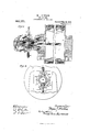
Referring to the accompanying drawings Figure 1 is a vertical sectional view taken through the head and cylinder, said view illustrating the connections by which fluid is supplied to and led away from the cylinder. Fig. 2 is an end view of the construction shown in Fig. 11 Figs. 3 and 4 illustrate in cross-section and end elevation respectively a modified form of the construction.
In the drawings, 1 represents the cylinder, the cylinder being provided with journals 2, 3, these journals being supported in journal boxes of the usual type. The journal 3 is made hollow, as illustrated, to permit the introduction and withdrawal from the cylinder of steam or heating or cooling water, as the case may be. To the end of the hollow journal 3 of the cylinder is secured b y means of screws, 01' in any other suitable manner, a head or cap 4. In the best constructions, this head or cap 4 will have a projecting part, as 5, which may be chambored out so that its bore is slightly greater than the here through the body of the head, whereby a shoulder, indicated at 6, is pro duced.
In the particular construction illustrated, there is provided an induction pipe, marked 7, which leads through the head, a fluid tight joint being provided between the head ant this pipe. While the means for eifecting this tight joint may be varied, in the particular constructions illustrated, the pipe is sur rounded by a convex bearing surface 8 into which the pipe is secured, the bearing surface being further rigidly connected to the pipe by means of a key 9 or in any other suitable manner. This bearing surface forms a ground joint with the head, as shown. I there be fluid pressure in the cylinder, it will tend to force the bearing surface 8 against the surface of the head and thus keep the joint tight, but to prevent leakage, when the pressure is low in the cylinder, additional means may be employed for the purpose of keeping this joint tight. While these means may be varied, in the construction illustrated, a sleeve 10 is employed which extends into the chambered out portion of the head referred to, surrounds the induction pipe, and may be prevented from turning by being splined to said pipe, as indicated at 11. The end of the eduction pipe beyond the sleeve may be threaded, as indicated, and provided with an adjusting nut 12. Between the end of the sleeve and the shoulders 6 before referred to, there may be located a spring 13, the tension of which may be adjusted by turning the nut. The inner end of the spring may bear against a thrust collar, as 14, which maybe keyed to the induction pipe, as shown, which collar in turn rests against the shoulders 6 of the head before referred to. The chamber in which the spring lies may serve as an oil containing chamber for the bearing parts, the oil being supplied in any suitable manner, as by a cup 15 screwed into the sleeve 10, the oil being led into the chamber through a passage 15 formed in the sleeve. A felt washer, indicated at 16, against which the outer end of the spring bears, may be provided to assist in controlling the flow of the oil.
The fluid is supplied to the induction pipe through pi ing 17, leading from a suitable source of uid su ply, not shown. While this piping may be supported in various ways, it will, in constructions involving the invention, be so supported that its weight is not carried by the induction pipe. Two con structions by which the invention may be carried into effect are illustrated. In both of these constructions, a supporting member for the piping is employed and the member is carried on the head referred to, so that the weight of the piping is sustained by the head. In the construction illustrated in Figs. 1 and 2, this supporting member is in the form of a casting 19 which is supported on the projecting part 5 of the head 4. This casting may be so formed as to provide both an induction and an eduction passage when, as in the constructions illustrated, both the induction and eduction pipes are at the same side of the cylinder. s shown, the casting is cored out to form an induction passage 20 and an eduction passage 21. Further, as illustrated in Fig. 1, the end of the piping 17 is screwed into a tapped opening 22 in the casting which opening communicates with the passage 20 before referred to. The end of this passage 20 may be in open communication with a tapped opening 23 also formed in the casting 19 in which opening the induction pipe 7 before referred to may be screwed. The casting 19 may further be provided with a tapped opening 24 into which eduction piping 2, may be screwed, this opening 24 being in communication with the passage 21. in order to provide for the carrying away of the condensed steam or other fluid employed in the cylinder, the casting 19 may be further provided with a tapped opening 2-6 in open communication with the passage 21 and into this opening an eduction pipe 27 may be screwed In the construction illustrated in Figs. 3 and 4, the su porting member comprises a collar 18 which may be provided with an elbow 28 which has a foot 29 connected there to, this foot being secured by screws 30 or in any other suitable manner to the collar 18. Beyond this elbow the piping 17 may be extended by sections 31, 32 which are connected by an elbow 33 to a head or fitting 34 which may be provided with two chambers 35, 36. This head or fitting may be secured to the end of the induction pipe 7 as illustrated, and the section 32 of the piping may be screwed into the head or fitting so as to communicate with the chamber 35 from which the induction pipe 7 leads. The collar 18 may be provided with a second elbow 37 seciired to the collar by a foot 33, the attachment being effected by screws 39, or in any other suitable manner, and the pipe 25 may be screwed into this elbow. Beyond the el bow, the pipe 25 may be continued by sections 40, 11 connected by an elbow 12 to the chamber 36, the section 41 into an opening in the fitting which leads into this chamber.
In the constructions described, it wili be seen that the induction pipe is relieved from the duty of supporting the weight of the lines of piping referred to as well as the fitting and tie eduction pipe, the weight of all these parts being finally sustained by the head which is bolted to the cylinder. With these constructions, therefore, the liability of wear between this pipe and the head is done away with and the ife of the pipe may be prolonged practically indefinitely.
Changes and variations may be made in the constructions herein shown and described for carrying the invention in to effect. The invention is not, therefore, to be limited to the specific constructions illustrated.
What is claimed is 1. The combination with a cylinder mounted to rotate and arranged to have its temperature determined by fluid introduced thereinto, of a pipe communicating with the interior of the cylinder, a head secured to the cylinder, a fluid tight joint between the head and the pipe, piping communicating with the pipe, and means independent of the pipe for supporting the piping, whereby the ipe is relieved from supporting the piping.
2. The combination with a cylinder mount ed to rotate and arranged to have its tem perature determined by fluid introduced thereinto, of a pipe communicating with the interior of the cylinder, a head secured to the cylinder said head raving a projecting part, a fluid tight joint between the head and the pipe, piping communicating with the pipe, and means whereby the projecting part of the head is caused to sustain the weight of the pi ing. 7
3. T 1e combination with a cylinder mounted to rotate and arranged to have its ten1 perature determined by fluid introduced thereinto, of a pipe communicating with the interior of the cylinder, a head secured to the cylinder said head having a projecting part, a fluid tight joint between the head and the cylinder, piping communicating with the pipe, a supporting member mountbeing screwed ed on the projecting means whereby said sustain the weight of the piping.
4. The combination with a cylinder mounted to rotate and arranged to have its tem perature determined by fluid introduced thereinto, of a head secured thereto, fluid induction and eduction pipes passing through the head one of said pipes being inside the other, a fluid tight joint between the outer pipe and the head, piping communicating with said induction and eduction pipes, and means independent of said pipes for supporting the piping.
5. The combination with a cylinder mounted to rotate and arranged to have its temperature determined by fluid introduced thereinto, of a head secured thereto said head having a projecting part, induction and eduction pipes passing through the head one of said pipes being within the other, a fluid tight joint between the outer pipe and the head, piping communicating with said pipes, and means whereby the projecting part of the head is caused to sustain the weight of the piping.
6 The combination ed to rotate and member is caused to with a cylinder mo untarranged to have its temperature determined by fluid introduced thereinto, of a head secured thereto said head having a projecting part, induction and eduction pipes passing through the head one of said pipes being within the other, a fluid tight oint between the head and the outer pipe, a supporting member mounted on the projecting part of the hear, piping, and an intermediate communicating connection between said piping and pipe, said connection and piping being carried by the supporting member, whereby the weight of the piping and connection is supported by the head.
7. The combination with a cylinder mounted to rotate and arranged to have its temperby fluid introduced thereature determined into, of a head secured thereto, said head having a pro ecting part, a cast ng supported on the said pro ecting part, piping connected the casting and extending into the interior of the cylinder, said casting being formed to provide a communicating passage between the piping and the pipe, whereby the head sustains the weight of the piping.
8. The combination ed to rotate and arranged to have its temperature determined by fluid introduced thereinto, of a head secured thereto, said head having a projecting part, a casting supported on said pro ecting ing to the interior of the cylinder, and induction and eduction iart, induction and educj tion pipes connected to the casting and leadpiping connected to the part of the head, and
J l i l I I I j l l i l l l l i passages by which the tight joint between to the casting, and a pipe also connected to l j adjusting the the spring, and piping connected to the castwithacylinder niount- I casting, said casting being formed to provide pipes are connected with the piping.
9. The combination with a cylinder mounted to rotate and arranged to have its temperature determined by fluid introduced thereinto, of a head secured thereto, said head having a chambered projecting part, a pipe passing through said projecting part and communicating with the interior of the cylinder, a fluid tight joint between the head and the pipe, a sleeve surrounding the pipe and lying in the chambered portion of the head, a spring between the end of the sleeve and the body of the head, means for adjusting the sleeve to vary the tension of the spring, piping whereby fluid is supplied to the pipe, and means whereby the projecting portion of the head is caused to sustain the weight of the piping.
10. The combination with a cylinder mounted to rotate and arranged to have its temperature determined by a head secured thereto, said head having a chambered projecting part, induction and eduction pipes passing through the head, one of said pipes lying inside the other, a fluid tight joint between the head and the outer pipe, a sleeve surrounding the outer pipe and lying in the chambered portion of the head, a spring between the sleeve and the body of the head, means for adjusting the sleeve to vary the tension of the spring, intermediate communicating connections between the piping and the pipes, and a supporting member on the projecting portion of the head whereby the head sustains the weight of the piping.
11. The combination with a cylinder mounted to rotate and arranged to have its temperature determined by fluid introduced thereinto, of a head secured thereto, said head having a chambered projecting part, a casting supported on the head, induction and eduction pipes passing through the head, one of said pipes lying within the other and said pipes being connected to the casting, a fluid the body of the head and the outer pipe, a sleeve surrounding the outer pipe and lying in the chambered portion of the head, a spring between the end of the sleeve and the body of the head, means for sleeve to vary the tension of said casting being formed to provide passages between the piping and the pipes.
In testimony whereof, I have hereunto set my hand, in the presence of two subscribing wltnesses.
MYRON J. WHITLOOK. Witnesses:
NORMAN P. KNIGHT. B. O. HALE.
Priority Applications (1)
| Application Number | Priority Date | Filing Date | Title |
|---|---|---|---|
| US41507708A US921771A (en) | 1908-02-10 | 1908-02-10 | Hollow roll. |
Applications Claiming Priority (1)
| Application Number | Priority Date | Filing Date | Title |
|---|---|---|---|
| US41507708A US921771A (en) | 1908-02-10 | 1908-02-10 | Hollow roll. |
Publications (1)
| Publication Number | Publication Date |
|---|---|
| US921771A true US921771A (en) | 1909-05-18 |
Family
ID=2990204
Family Applications (1)
| Application Number | Title | Priority Date | Filing Date |
|---|---|---|---|
| US41507708A Expired - Lifetime US921771A (en) | 1908-02-10 | 1908-02-10 | Hollow roll. |
Country Status (1)
| Country | Link |
|---|---|
| US (1) | US921771A (en) |
Cited By (5)
| Publication number | Priority date | Publication date | Assignee | Title |
|---|---|---|---|---|
| US2460872A (en) * | 1945-07-16 | 1949-02-08 | Carpenter Russell | Steam joint |
| US2705650A (en) * | 1950-07-15 | 1955-04-05 | Du Pont | Balanced rotary fluid seal |
| US2745684A (en) * | 1952-03-29 | 1956-05-15 | Crown Zellerbach Corp | Rotary steam joint and loose mounting therefor |
| US2758850A (en) * | 1950-12-15 | 1956-08-14 | Logansport Machine Co Inc | Rotating shaft and seal |
| US3675846A (en) * | 1970-06-15 | 1972-07-11 | Bio Consultants Inc | Continuous flow centrifuge head construction |
-
1908
- 1908-02-10 US US41507708A patent/US921771A/en not_active Expired - Lifetime
Cited By (5)
| Publication number | Priority date | Publication date | Assignee | Title |
|---|---|---|---|---|
| US2460872A (en) * | 1945-07-16 | 1949-02-08 | Carpenter Russell | Steam joint |
| US2705650A (en) * | 1950-07-15 | 1955-04-05 | Du Pont | Balanced rotary fluid seal |
| US2758850A (en) * | 1950-12-15 | 1956-08-14 | Logansport Machine Co Inc | Rotating shaft and seal |
| US2745684A (en) * | 1952-03-29 | 1956-05-15 | Crown Zellerbach Corp | Rotary steam joint and loose mounting therefor |
| US3675846A (en) * | 1970-06-15 | 1972-07-11 | Bio Consultants Inc | Continuous flow centrifuge head construction |
Similar Documents
| Publication | Publication Date | Title |
|---|---|---|
| US921771A (en) | Hollow roll. | |
| US1991432A (en) | Drier mechanism for paper making machines | |
| US859426A (en) | Flexible pipe-joint. | |
| US1558630A (en) | Hydraulic seal for rotary engines | |
| US1162825A (en) | Selecting-valve device. | |
| US1769905A (en) | Steam joint | |
| US285476A (en) | Paper calender-roll | |
| US537172A (en) | Self-oiling journal-bearing | |
| US774270A (en) | Oiling device for refrigerating-machines. | |
| US1665614A (en) | Paper-making machine | |
| US1252490A (en) | Hydraulic, steam, or air valve. | |
| US2101937A (en) | Swivel pipe joint | |
| US1348664A (en) | Oiling device | |
| US1546394A (en) | Roll for paper and similar machines | |
| US649779A (en) | Strainer-plug for lubricators. | |
| US556074A (en) | Lubricator | |
| US1080858A (en) | Radiator-valve. | |
| US2343022A (en) | Means for cooling and lubricating mandrel bars | |
| US763399A (en) | Journal box or bearing for roll-shafts. | |
| US658052A (en) | Journal-box for washing-machines. | |
| US635512A (en) | Pipe-joint for hollow revolving journals. | |
| GB191321001A (en) | Improvements in or connected with Mixing and Calendering Rolls for India Rubber and other Plastic Materials. | |
| GB190907111A (en) | Improved Means for use in Passing Steam, or other Fluids, into and from Rotating Cylinders and the like. | |
| US1173218A (en) | Mine-car wheel and bearing. | |
| GB191504316A (en) | Improvements in and relating to Appliances for Operating the Doctors on the Calenders of Papermaking Machines. |