US9214876B2 - Method of shoot-through generation for modified sine wave Z-source, quasi-Z-source and trans-Z-source inverters - Google Patents
Method of shoot-through generation for modified sine wave Z-source, quasi-Z-source and trans-Z-source inverters Download PDFInfo
- Publication number
- US9214876B2 US9214876B2 US14/001,891 US201214001891A US9214876B2 US 9214876 B2 US9214876 B2 US 9214876B2 US 201214001891 A US201214001891 A US 201214001891A US 9214876 B2 US9214876 B2 US 9214876B2
- Authority
- US
- United States
- Prior art keywords
- shoot
- source
- states
- freewheeling
- inverter
- Prior art date
- Legal status (The legal status is an assumption and is not a legal conclusion. Google has not performed a legal analysis and makes no representation as to the accuracy of the status listed.)
- Expired - Fee Related, expires
Links
- 238000000034 method Methods 0.000 title claims abstract description 27
- 230000010363 phase shift Effects 0.000 abstract description 4
- 239000004065 semiconductor Substances 0.000 abstract description 2
- 239000008186 active pharmaceutical agent Substances 0.000 description 3
- 239000003990 capacitor Substances 0.000 description 2
- 238000009413 insulation Methods 0.000 description 2
- 238000010586 diagram Methods 0.000 description 1
Images


Classifications
-
- H—ELECTRICITY
- H02—GENERATION; CONVERSION OR DISTRIBUTION OF ELECTRIC POWER
- H02M—APPARATUS FOR CONVERSION BETWEEN AC AND AC, BETWEEN AC AND DC, OR BETWEEN DC AND DC, AND FOR USE WITH MAINS OR SIMILAR POWER SUPPLY SYSTEMS; CONVERSION OF DC OR AC INPUT POWER INTO SURGE OUTPUT POWER; CONTROL OR REGULATION THEREOF
- H02M7/00—Conversion of ac power input into dc power output; Conversion of dc power input into ac power output
- H02M7/42—Conversion of dc power input into ac power output without possibility of reversal
- H02M7/44—Conversion of dc power input into ac power output without possibility of reversal by static converters
- H02M7/48—Conversion of dc power input into ac power output without possibility of reversal by static converters using discharge tubes with control electrode or semiconductor devices with control electrode
- H02M7/505—Conversion of dc power input into ac power output without possibility of reversal by static converters using discharge tubes with control electrode or semiconductor devices with control electrode using devices of a thyratron or thyristor type requiring extinguishing means
- H02M7/515—Conversion of dc power input into ac power output without possibility of reversal by static converters using discharge tubes with control electrode or semiconductor devices with control electrode using devices of a thyratron or thyristor type requiring extinguishing means using semiconductor devices only
- H02M7/523—Conversion of dc power input into ac power output without possibility of reversal by static converters using discharge tubes with control electrode or semiconductor devices with control electrode using devices of a thyratron or thyristor type requiring extinguishing means using semiconductor devices only with LC-resonance circuit in the main circuit
-
- H—ELECTRICITY
- H02—GENERATION; CONVERSION OR DISTRIBUTION OF ELECTRIC POWER
- H02M—APPARATUS FOR CONVERSION BETWEEN AC AND AC, BETWEEN AC AND DC, OR BETWEEN DC AND DC, AND FOR USE WITH MAINS OR SIMILAR POWER SUPPLY SYSTEMS; CONVERSION OF DC OR AC INPUT POWER INTO SURGE OUTPUT POWER; CONTROL OR REGULATION THEREOF
- H02M7/00—Conversion of ac power input into dc power output; Conversion of dc power input into ac power output
- H02M7/42—Conversion of dc power input into ac power output without possibility of reversal
- H02M7/44—Conversion of dc power input into ac power output without possibility of reversal by static converters
- H02M7/48—Conversion of dc power input into ac power output without possibility of reversal by static converters using discharge tubes with control electrode or semiconductor devices with control electrode
- H02M7/4826—Conversion of dc power input into ac power output without possibility of reversal by static converters using discharge tubes with control electrode or semiconductor devices with control electrode operating from a resonant DC source, i.e. the DC input voltage varies periodically, e.g. resonant DC-link inverters
Definitions
- This invention belongs in the field of power electronics and semiconductor converter control and pertains to the methods of shoot-through generation for modified sine wave Z-source, quasi-Z-source and trans-Z-source inverters.
- Z-source, quasi-Z-source and trans-Z-source inverters are new DC/AC (voltage) converters in power electronics. These make it possible to both increase and decrease input voltage without additional switching elements.
- These converters consist of an LC circuit (of Z-source, quasi-Z-source or trans-Z-source-type) and a single-phase or multi-phase inverter ( FIG. 1 ).
- the voltage amplitude is increased by a specific shoot-through state that is generated by turning on the switching elements of one bridge arm of the inverter simultaneously.
- the energy of the magnetic field is accumulated in the chokes of LC circuits without short-circuiting the capacitors during the shoot-through.
- the accumulated energy is used to increase the voltage of the DC-link during the traditional conductivity phase that follows the shoot-through.
- Such inverters are meant for various power electronics applications where flexible control and reliability of a device are especially important.
- Z-source, quasi-Z-source, and trans-Z-source inverters are controlled using modified sine wave modulation methods with shoot-through states: pulse-width modulation (PWM) or phase-shift modulation (PSM).
- PWM pulse-width modulation
- PSM phase-shift modulation
- a shoot-through state is added to the modified sine wave signal and the relative duration of the shoot-through determines the voltage amplitude of the DC-link.
- Shoot-through states are distributed across the period in a way that the number of higher harmonics would be minimal in the output voltage of the inverter. To reduce the switching and conductivity losses, the number of shoot-through states per switching period is limited to two and the shoot-through current is distributed equally across the transistors of both arms of the inverter.
- the pulse width is kept constant.
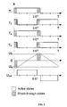
- the output of the inverter is adjusted by changing the mutual phase angle of the control signals and the duration of a shoot-through ( FIG. 5 ).
- a shoot-through is generated during zero states.
- the prerequisite is that the duration of the zero state (t Z ) is longer than the maximum duration of the shoot-through state.
- the switching period consists of three parts: an active state, a shoot-through state and a zero state.
- the upper and lower switching element groups take turns to generate a zero state. This ensures equal operating frequency of the switching elements. If the operating frequency of switching elements is equal, the switching losses are equal as well and the switching elements have an equal load.
- Patent US005784267A concerning a modified sine wave method is already known.
- An AC converter is controlled using a modified sine wave method without shoot-through states.
- the disadvantage of this method is that the voltage cannot be increased.
- a Z-source inverter described in US2009066271 is known.
- the Z-source inverter is used for generating a three-phase sine voltage.
- the voltage is increased by shoot-through states integrated into the control algorithm.
- the disadvantage of the described solution is that it applies only to sine wave modulation and does not determine the methods for shoot-through generation.
- a current source inverter described in WO9421021 is also known. Some switching elements, a capacitor and two chokes are added to a three-phase current source inverter to achieve soft switching.
- the inverter operates using sine wave modulation.
- the disadvantage of the inverter is that it does not enable to generate freewheeling, zero or shoot-through states.
- the switching period of a Z-source, quasi-Z-source and trans-Z-source inverter may consist of the following states: zero, freewheeling, active and shoot-through.
- the zero state is when the load is short circuited by switching on all upper or lower switching elements of the inverter simultaneously.
- the freewheeling state is achieved when all switching elements of an inverter are switched off simultaneously, and no current is generated in the output of the inverter.
- the active state occurs when only one switching element in each bridge arm of the inverter is turned on and current is generated in the output of the inverter.
- the shoot-through state occurs when top and bottom switching elements of a bridge arm or all switching elements of a bridge are switched on simultaneously.
- FIG. 1 depicts the circuit diagram of a Z-source, quasi-Z-source or trans-Z-source inverter.
- FIG. 2 depicts PWM control where shoot-through states are generated by overlapping active states.
- FIG. 3 depicts PWM control where shoot-through states are generated during freewheeling states.
- FIG. 4 depicts PWM control where shoot-through states are generated during zero states.
- FIG. 5 depicts PSM control with shoot-through states.
- FIGS. 1-5 contain the following symbols:
- T 1 , T 2 , T 3 , T 4 switching elements of the inverter
- the principle of the invention is described on the basis of a single-phase inverter.
- the voltage from the input voltage source ( 1 ) is directed through the Z-source, quasi-Z-source or trans-Z-source circuit ( 2 ) into a single- or multi-phase inverter ( 3 ).
- the inverter ( 3 ) consists of switching elements T 1 , T 2 , T 3 and T 4 (the inverter may also be a multi-phase one).
- the inverter can be controlled using either the modified sine wave pulse-width modulation (PWM) or phase-shift modulation (PSM) method.
- PWM modified sine wave pulse-width modulation
- PSM phase-shift modulation
- a transformer, an AC motor, an AC load, etc., are connected to the output of the inverter ( 3 ).
- Zero, freewheeling and shoot-through states are distributed across the period (T) in a way that the number of higher harmonics is minimal in the output voltage of the inverter.
- the number of shoot-through states per switching period is limited to two and the shoot-through current is distributed equally across the transistors of both arms of the inverter.
- the control signals have a constant period and phase shift.
- the output voltage of the inverter is adjusted by changing the pulse width and the duration of a shoot-through.
- shoot-through states There are three methods one can choose from to generate shoot-through states: by overlapping active states, during the freewheeling state and during the zero state.
- FIGS. 2( a ) and 2 ( b ) depict control signals of a single-phase inverter; these are called conductivity states.
- the duty cycle of the switching elements (T 1 /T 4 and T 2 /T 3 ) of each of the two diagonals is 0.5.
- the duty cycle of both switching element pairs is increased, resulting in overlapping active states, i.e. shoot-through active states. This results in a symmetric output voltage of the inverter ( FIG. 2( e )), the amplitude of the voltage being U DC .
- the switching period of this control method consists of active and shoot-through active states:
- t A and t S are durations of active and shoot-through active states, respectively
- D A and D S are relative durations of active and shoot-through active states, respectively.
- the formula indicates that by changing the duration of the active states of the switching elements, the duration of shoot-through active states changes automatically.
- the method for shoot-through generation during freewheeling states is depicted in FIG. 3 .
- a shoot-through is generated during a freewheeling state where all switching elements are switched off and the current passes through freewheeling diodes.
- the prerequisite is that the duration of freewheeling is longer than the maximum duration of the shoot-through.
- the switching period consists of three parts: an active state, a shoot-through freewheeling state and a freewheeling state.
- the load is short-circuited and a zero state is generated ( FIG. 4 ).
- a shoot-through state is generated during a zero state.
- the prerequisite is that the duration of the zero state (t Z ) is longer than the maximum duration of the shoot-through state.
- the switching period consists of three parts: an active state, a shoot-through zero state and a zero state.
- Adding shoot-through zero states changes the switching pattern of switching elements unsymmetrical, as shown in FIG. 4 .
- the switching frequency of top and bottom side switching elements is different ( FIG. 4 ), thus also switching losses.
- the control signals of upper and lower switching elements are periodically interchanged e.g. the control signal of T 1 is interchanged with T 4 and T 2 is interchanged with T 3 .
- Minimum time interval between two immediate interchanges is one switching period.
Landscapes
- Engineering & Computer Science (AREA)
- Power Engineering (AREA)
- Inverter Devices (AREA)
- Ac-Ac Conversion (AREA)
Abstract
Description
where tA and tS are durations of active and shoot-through active states, respectively, and DA and DS are relative durations of active and shoot-through active states, respectively. The formula indicates that by changing the duration of the active states of the switching elements, the duration of shoot-through active states changes automatically.
where tA and tFRW are durations of the active and freewheeling states, tS is the duration of the shoot-through freewheeling state, DA and DS are relative durations of active and shoot-through freewheeling states, and DFRW is the relative duration of the freewheeling state.
where tA and tZ are the durations of the active and zero states, tS is the duration of the shoot-through zero state, DA and DS are relative durations of active and shoot-through zero states, and DZ is the relative duration of the zero state.
Claims (8)
Applications Claiming Priority (4)
| Application Number | Priority Date | Filing Date | Title |
|---|---|---|---|
| EEP201100013 | 2011-02-28 | ||
| EEP201100013A EE05654B1 (en) | 2011-02-28 | 2011-02-28 | Method for Generating Lines with Block-Controlled HV or Multi Phase Impedance, Quasi-Impedance, and Transimpedance |
| EE201100013 | 2011-02-28 | ||
| PCT/EE2012/000002 WO2012116708A2 (en) | 2011-02-28 | 2012-02-28 | Method of shoot-through generation for modified sine wave z-source, quasi-z-source and trans-z-source inverters |
Publications (2)
| Publication Number | Publication Date |
|---|---|
| US20130329477A1 US20130329477A1 (en) | 2013-12-12 |
| US9214876B2 true US9214876B2 (en) | 2015-12-15 |
Family
ID=45991992
Family Applications (1)
| Application Number | Title | Priority Date | Filing Date |
|---|---|---|---|
| US14/001,891 Expired - Fee Related US9214876B2 (en) | 2011-02-28 | 2012-02-28 | Method of shoot-through generation for modified sine wave Z-source, quasi-Z-source and trans-Z-source inverters |
Country Status (4)
| Country | Link |
|---|---|
| US (1) | US9214876B2 (en) |
| EP (1) | EP2681836A2 (en) |
| EE (1) | EE05654B1 (en) |
| WO (1) | WO2012116708A2 (en) |
Cited By (1)
| Publication number | Priority date | Publication date | Assignee | Title |
|---|---|---|---|---|
| US9979321B2 (en) | 2016-05-25 | 2018-05-22 | Casco Products Corporation | N-sine wave inverter |
Families Citing this family (9)
| Publication number | Priority date | Publication date | Assignee | Title |
|---|---|---|---|---|
| CN103117650B (en) * | 2013-01-24 | 2015-01-28 | 东南大学 | Quasi Z source inverter |
| WO2015138744A1 (en) | 2014-03-13 | 2015-09-17 | Qatar Foundation For Education, Science And Community Development | Modulation and control methods for quasi-z-source cascade multilevel inverters |
| CN103973152B (en) * | 2014-04-04 | 2016-10-05 | 深圳职业技术学院 | A kind of pulse width modulation control method and device |
| CN104578882B (en) * | 2015-01-28 | 2017-05-24 | 厦门大学 | Voltage type Tran-z-source miniature inverter |
| CN104716855A (en) * | 2015-04-09 | 2015-06-17 | 山东科技大学 | Current-type quasi-impedance source inverter with two-way power flow |
| CN104796030B (en) * | 2015-04-21 | 2017-09-22 | 西安理工大学 | Single-phase photovoltaic off-grid inverter and its soft switching control method based on quasi- Z-source inverter |
| KR101750808B1 (en) | 2015-08-18 | 2017-06-26 | 재단법인 자동차융합기술원 | Hybrid generation system |
| US11552551B2 (en) * | 2021-05-25 | 2023-01-10 | City University Of Hong Kong | Method of control of a system comprising a single-phase three-level T type quasi-Z source inverter connected to an LC filter which is in turn connected to a load |
| CN114583991B (en) * | 2022-05-07 | 2022-08-19 | 深圳古瑞瓦特新能源有限公司 | Gain-adjustable single-phase DCAC converter, control method and three-phase DCAC converter |
Citations (5)
| Publication number | Priority date | Publication date | Assignee | Title |
|---|---|---|---|---|
| WO1994021021A1 (en) | 1993-03-10 | 1994-09-15 | Electric Power Research Institute, Inc. | Neutral commutated soft switched current source inverters |
| US5784267A (en) | 1996-10-17 | 1998-07-21 | Onan Corporation | Quasi-sine wave and stepped square wave AC to AC converter |
| US20030231518A1 (en) | 2002-06-12 | 2003-12-18 | Peng Fang Z. | Impedance source power converter |
| US20090066271A1 (en) | 2007-09-12 | 2009-03-12 | Kajouke Lateef A | Method and system for converting dc power to ac power |
| US20110188272A1 (en) * | 2008-06-27 | 2011-08-04 | Keyue Smedley | Circuit for direct energy extraction from a charged-particle beam |
-
2011
- 2011-02-28 EE EEP201100013A patent/EE05654B1/en not_active IP Right Cessation
-
2012
- 2012-02-28 WO PCT/EE2012/000002 patent/WO2012116708A2/en active Application Filing
- 2012-02-28 EP EP20120715580 patent/EP2681836A2/en not_active Withdrawn
- 2012-02-28 US US14/001,891 patent/US9214876B2/en not_active Expired - Fee Related
Patent Citations (5)
| Publication number | Priority date | Publication date | Assignee | Title |
|---|---|---|---|---|
| WO1994021021A1 (en) | 1993-03-10 | 1994-09-15 | Electric Power Research Institute, Inc. | Neutral commutated soft switched current source inverters |
| US5784267A (en) | 1996-10-17 | 1998-07-21 | Onan Corporation | Quasi-sine wave and stepped square wave AC to AC converter |
| US20030231518A1 (en) | 2002-06-12 | 2003-12-18 | Peng Fang Z. | Impedance source power converter |
| US20090066271A1 (en) | 2007-09-12 | 2009-03-12 | Kajouke Lateef A | Method and system for converting dc power to ac power |
| US20110188272A1 (en) * | 2008-06-27 | 2011-08-04 | Keyue Smedley | Circuit for direct energy extraction from a charged-particle beam |
Non-Patent Citations (15)
Cited By (1)
| Publication number | Priority date | Publication date | Assignee | Title |
|---|---|---|---|---|
| US9979321B2 (en) | 2016-05-25 | 2018-05-22 | Casco Products Corporation | N-sine wave inverter |
Also Published As
| Publication number | Publication date |
|---|---|
| WO2012116708A2 (en) | 2012-09-07 |
| EE201100013A (en) | 2012-10-15 |
| EE05654B1 (en) | 2013-04-15 |
| US20130329477A1 (en) | 2013-12-12 |
| WO2012116708A3 (en) | 2012-11-08 |
| EP2681836A2 (en) | 2014-01-08 |
Similar Documents
| Publication | Publication Date | Title |
|---|---|---|
| US9214876B2 (en) | Method of shoot-through generation for modified sine wave Z-source, quasi-Z-source and trans-Z-source inverters | |
| Buticchi et al. | A nine-level grid-connected converter topology for single-phase transformerless PV systems | |
| Buticchi et al. | A five-level single-phase grid-connected converter for renewable distributed systems | |
| Loh et al. | Topological and modulation design of three-level Z-source inverters | |
| US8559193B2 (en) | Zero-voltage-switching scheme for high-frequency converter | |
| Gurpinar et al. | Performance analysis of SiC MOSFET based 3-level ANPC grid-connected inverter with novel modulation scheme | |
| CN103283135A (en) | Electric power converter | |
| US9680376B2 (en) | Power conversion electronics having conversion and inverter circuitry | |
| EP3151412B1 (en) | Power conversion device and three-phase ac power supply device | |
| Lee et al. | An improved phase-shifted PWM method for a three-phase cascaded H-bridge multi-level inverter | |
| US20200169171A1 (en) | DC Coupled Electrical Converter | |
| US10312825B2 (en) | Five-level half bridge inverter topology with high voltage utilization ratio | |
| Zhang et al. | A hybrid modulation method for single-phase quasi-Z source inverter | |
| Sayed et al. | Grid-connected single-phase multi-level inverter | |
| Gaikwad et al. | Survey of PWM techniques for solar inverter | |
| CN103618336A (en) | Output digital modulation circuit and control system of rectifier type high-frequency chain grid-connected inverter | |
| Qin et al. | Influence of the overlap time on the AC grid current of CSR and its restraining method | |
| US20140265641A1 (en) | Zero current switching with a secondary energy storage capacitor in a solar inverter | |
| Prathiba et al. | Multi carrier PWM based multi level inverter for high power applications | |
| JP6440067B2 (en) | Power converter | |
| Hari et al. | A dynamic analysis of SVM based three-level NPC for a 3-phase induction motor | |
| Lawan et al. | Level shifted PWMs comparison for a 5-level modular multilevel converter (MMC) topology inverter | |
| RU2540110C2 (en) | Reversible frequency converter | |
| Luchetta et al. | Multilevel DC-AC converters for renewable power generation plants: comparison, simulation, and experimental tests | |
| Buticchi et al. | A novel five-level single phase grid connected converter for renewable distributed systems |
Legal Events
| Date | Code | Title | Description |
|---|---|---|---|
| AS | Assignment |
Owner name: TALLINN UNIVERSITY OF TECHNOLOGY, ESTONIA Free format text: ASSIGNMENT OF ASSIGNORS INTEREST;ASSIGNORS:VINNIKOV, DMITRI;JALAKAS, TANEL;ROASTO, INDREK;AND OTHERS;REEL/FRAME:031098/0806 Effective date: 20130824 |
|
| AS | Assignment |
Owner name: OUE UBIK SOLUTIONS, ESTONIA Free format text: ASSIGNMENT OF ASSIGNORS INTEREST;ASSIGNOR:TALLINN UNIVERSITY OF TECHNOLOGY;REEL/FRAME:033124/0545 Effective date: 20140616 |
|
| FEPP | Fee payment procedure |
Free format text: PAYOR NUMBER ASSIGNED (ORIGINAL EVENT CODE: ASPN); ENTITY STATUS OF PATENT OWNER: SMALL ENTITY |
|
| STCF | Information on status: patent grant |
Free format text: PATENTED CASE |
|
| CC | Certificate of correction | ||
| MAFP | Maintenance fee payment |
Free format text: PAYMENT OF MAINTENANCE FEE, 4TH YR, SMALL ENTITY (ORIGINAL EVENT CODE: M2551); ENTITY STATUS OF PATENT OWNER: SMALL ENTITY Year of fee payment: 4 |
|
| FEPP | Fee payment procedure |
Free format text: MAINTENANCE FEE REMINDER MAILED (ORIGINAL EVENT CODE: REM.); ENTITY STATUS OF PATENT OWNER: SMALL ENTITY |
|
| LAPS | Lapse for failure to pay maintenance fees |
Free format text: PATENT EXPIRED FOR FAILURE TO PAY MAINTENANCE FEES (ORIGINAL EVENT CODE: EXP.); ENTITY STATUS OF PATENT OWNER: SMALL ENTITY |
|
| STCH | Information on status: patent discontinuation |
Free format text: PATENT EXPIRED DUE TO NONPAYMENT OF MAINTENANCE FEES UNDER 37 CFR 1.362 |
|
| FP | Lapsed due to failure to pay maintenance fee |
Effective date: 20231215 |