US9209477B2 - Energy storage cell for a multi-cell energy storage device - Google Patents
Energy storage cell for a multi-cell energy storage device Download PDFInfo
- Publication number
- US9209477B2 US9209477B2 US13/938,898 US201313938898A US9209477B2 US 9209477 B2 US9209477 B2 US 9209477B2 US 201313938898 A US201313938898 A US 201313938898A US 9209477 B2 US9209477 B2 US 9209477B2
- Authority
- US
- United States
- Prior art keywords
- cell
- energy storage
- storage device
- integrated circuit
- voltage supply
- Prior art date
- Legal status (The legal status is an assumption and is not a legal conclusion. Google has not performed a legal analysis and makes no representation as to the accuracy of the status listed.)
- Active, expires
Links
Images


Classifications
-
- H—ELECTRICITY
- H01—ELECTRIC ELEMENTS
- H01M—PROCESSES OR MEANS, e.g. BATTERIES, FOR THE DIRECT CONVERSION OF CHEMICAL ENERGY INTO ELECTRICAL ENERGY
- H01M10/00—Secondary cells; Manufacture thereof
- H01M10/04—Construction or manufacture in general
-
- B60L11/1866—
-
- B—PERFORMING OPERATIONS; TRANSPORTING
- B60—VEHICLES IN GENERAL
- B60L—PROPULSION OF ELECTRICALLY-PROPELLED VEHICLES; SUPPLYING ELECTRIC POWER FOR AUXILIARY EQUIPMENT OF ELECTRICALLY-PROPELLED VEHICLES; ELECTRODYNAMIC BRAKE SYSTEMS FOR VEHICLES IN GENERAL; MAGNETIC SUSPENSION OR LEVITATION FOR VEHICLES; MONITORING OPERATING VARIABLES OF ELECTRICALLY-PROPELLED VEHICLES; ELECTRIC SAFETY DEVICES FOR ELECTRICALLY-PROPELLED VEHICLES
- B60L3/00—Electric devices on electrically-propelled vehicles for safety purposes; Monitoring operating variables, e.g. speed, deceleration or energy consumption
- B60L3/0023—Detecting, eliminating, remedying or compensating for drive train abnormalities, e.g. failures within the drive train
- B60L3/0046—Detecting, eliminating, remedying or compensating for drive train abnormalities, e.g. failures within the drive train relating to electric energy storage systems, e.g. batteries or capacitors
-
- B—PERFORMING OPERATIONS; TRANSPORTING
- B60—VEHICLES IN GENERAL
- B60L—PROPULSION OF ELECTRICALLY-PROPELLED VEHICLES; SUPPLYING ELECTRIC POWER FOR AUXILIARY EQUIPMENT OF ELECTRICALLY-PROPELLED VEHICLES; ELECTRODYNAMIC BRAKE SYSTEMS FOR VEHICLES IN GENERAL; MAGNETIC SUSPENSION OR LEVITATION FOR VEHICLES; MONITORING OPERATING VARIABLES OF ELECTRICALLY-PROPELLED VEHICLES; ELECTRIC SAFETY DEVICES FOR ELECTRICALLY-PROPELLED VEHICLES
- B60L58/00—Methods or circuit arrangements for monitoring or controlling batteries or fuel cells, specially adapted for electric vehicles
- B60L58/10—Methods or circuit arrangements for monitoring or controlling batteries or fuel cells, specially adapted for electric vehicles for monitoring or controlling batteries
- B60L58/12—Methods or circuit arrangements for monitoring or controlling batteries or fuel cells, specially adapted for electric vehicles for monitoring or controlling batteries responding to state of charge [SoC]
-
- B—PERFORMING OPERATIONS; TRANSPORTING
- B60—VEHICLES IN GENERAL
- B60L—PROPULSION OF ELECTRICALLY-PROPELLED VEHICLES; SUPPLYING ELECTRIC POWER FOR AUXILIARY EQUIPMENT OF ELECTRICALLY-PROPELLED VEHICLES; ELECTRODYNAMIC BRAKE SYSTEMS FOR VEHICLES IN GENERAL; MAGNETIC SUSPENSION OR LEVITATION FOR VEHICLES; MONITORING OPERATING VARIABLES OF ELECTRICALLY-PROPELLED VEHICLES; ELECTRIC SAFETY DEVICES FOR ELECTRICALLY-PROPELLED VEHICLES
- B60L58/00—Methods or circuit arrangements for monitoring or controlling batteries or fuel cells, specially adapted for electric vehicles
- B60L58/10—Methods or circuit arrangements for monitoring or controlling batteries or fuel cells, specially adapted for electric vehicles for monitoring or controlling batteries
- B60L58/18—Methods or circuit arrangements for monitoring or controlling batteries or fuel cells, specially adapted for electric vehicles for monitoring or controlling batteries of two or more battery modules
- B60L58/22—Balancing the charge of battery modules
-
- H—ELECTRICITY
- H01—ELECTRIC ELEMENTS
- H01M—PROCESSES OR MEANS, e.g. BATTERIES, FOR THE DIRECT CONVERSION OF CHEMICAL ENERGY INTO ELECTRICAL ENERGY
- H01M10/00—Secondary cells; Manufacture thereof
- H01M10/42—Methods or arrangements for servicing or maintenance of secondary cells or secondary half-cells
- H01M10/425—Structural combination with electronic components, e.g. electronic circuits integrated to the outside of the casing
- H01M10/4257—Smart batteries, e.g. electronic circuits inside the housing of the cells or batteries
-
- H—ELECTRICITY
- H01—ELECTRIC ELEMENTS
- H01M—PROCESSES OR MEANS, e.g. BATTERIES, FOR THE DIRECT CONVERSION OF CHEMICAL ENERGY INTO ELECTRICAL ENERGY
- H01M10/00—Secondary cells; Manufacture thereof
- H01M10/42—Methods or arrangements for servicing or maintenance of secondary cells or secondary half-cells
- H01M10/48—Accumulators combined with arrangements for measuring, testing or indicating the condition of cells, e.g. the level or density of the electrolyte
- H01M10/482—Accumulators combined with arrangements for measuring, testing or indicating the condition of cells, e.g. the level or density of the electrolyte for several batteries or cells simultaneously or sequentially
-
- H—ELECTRICITY
- H01—ELECTRIC ELEMENTS
- H01M—PROCESSES OR MEANS, e.g. BATTERIES, FOR THE DIRECT CONVERSION OF CHEMICAL ENERGY INTO ELECTRICAL ENERGY
- H01M10/00—Secondary cells; Manufacture thereof
- H01M10/42—Methods or arrangements for servicing or maintenance of secondary cells or secondary half-cells
- H01M10/48—Accumulators combined with arrangements for measuring, testing or indicating the condition of cells, e.g. the level or density of the electrolyte
- H01M10/486—Accumulators combined with arrangements for measuring, testing or indicating the condition of cells, e.g. the level or density of the electrolyte for measuring temperature
-
- H02J7/0054—
-
- H—ELECTRICITY
- H02—GENERATION; CONVERSION OR DISTRIBUTION OF ELECTRIC POWER
- H02J—ELECTRIC POWER NETWORKS; CIRCUIT ARRANGEMENTS OR SYSTEMS FOR SUPPLYING OR DISTRIBUTING ELECTRIC POWER; SYSTEMS FOR STORING ELECTRIC ENERGY
- H02J7/00—Circuit arrangements for charging or discharging batteries or for supplying loads from batteries
- H02J7/34—Parallel operation in networks using both storage and other DC sources, e.g. providing buffering
- H02J7/342—The other DC source being a battery actively interacting with the first one, i.e. battery to battery charging
-
- B—PERFORMING OPERATIONS; TRANSPORTING
- B60—VEHICLES IN GENERAL
- B60L—PROPULSION OF ELECTRICALLY-PROPELLED VEHICLES; SUPPLYING ELECTRIC POWER FOR AUXILIARY EQUIPMENT OF ELECTRICALLY-PROPELLED VEHICLES; ELECTRODYNAMIC BRAKE SYSTEMS FOR VEHICLES IN GENERAL; MAGNETIC SUSPENSION OR LEVITATION FOR VEHICLES; MONITORING OPERATING VARIABLES OF ELECTRICALLY-PROPELLED VEHICLES; ELECTRIC SAFETY DEVICES FOR ELECTRICALLY-PROPELLED VEHICLES
- B60L2240/00—Control parameters of input or output; Target parameters
- B60L2240/40—Drive Train control parameters
- B60L2240/54—Drive Train control parameters related to batteries
- B60L2240/545—Temperature
-
- B—PERFORMING OPERATIONS; TRANSPORTING
- B60—VEHICLES IN GENERAL
- B60L—PROPULSION OF ELECTRICALLY-PROPELLED VEHICLES; SUPPLYING ELECTRIC POWER FOR AUXILIARY EQUIPMENT OF ELECTRICALLY-PROPELLED VEHICLES; ELECTRODYNAMIC BRAKE SYSTEMS FOR VEHICLES IN GENERAL; MAGNETIC SUSPENSION OR LEVITATION FOR VEHICLES; MONITORING OPERATING VARIABLES OF ELECTRICALLY-PROPELLED VEHICLES; ELECTRIC SAFETY DEVICES FOR ELECTRICALLY-PROPELLED VEHICLES
- B60L2240/00—Control parameters of input or output; Target parameters
- B60L2240/40—Drive Train control parameters
- B60L2240/54—Drive Train control parameters related to batteries
- B60L2240/547—Voltage
-
- B—PERFORMING OPERATIONS; TRANSPORTING
- B60—VEHICLES IN GENERAL
- B60L—PROPULSION OF ELECTRICALLY-PROPELLED VEHICLES; SUPPLYING ELECTRIC POWER FOR AUXILIARY EQUIPMENT OF ELECTRICALLY-PROPELLED VEHICLES; ELECTRODYNAMIC BRAKE SYSTEMS FOR VEHICLES IN GENERAL; MAGNETIC SUSPENSION OR LEVITATION FOR VEHICLES; MONITORING OPERATING VARIABLES OF ELECTRICALLY-PROPELLED VEHICLES; ELECTRIC SAFETY DEVICES FOR ELECTRICALLY-PROPELLED VEHICLES
- B60L2240/00—Control parameters of input or output; Target parameters
- B60L2240/40—Drive Train control parameters
- B60L2240/54—Drive Train control parameters related to batteries
- B60L2240/549—Current
-
- G01R31/3658—
-
- G—PHYSICS
- G01—MEASURING; TESTING
- G01R—MEASURING ELECTRIC VARIABLES; MEASURING MAGNETIC VARIABLES
- G01R31/00—Arrangements for testing electric properties; Arrangements for locating electric faults; Arrangements for electrical testing characterised by what is being tested not provided for elsewhere
- G01R31/36—Arrangements for testing, measuring or monitoring the electrical condition of accumulators or electric batteries, e.g. capacity or state of charge [SoC]
- G01R31/396—Acquisition or processing of data for testing or for monitoring individual cells or groups of cells within a battery
-
- H—ELECTRICITY
- H01—ELECTRIC ELEMENTS
- H01M—PROCESSES OR MEANS, e.g. BATTERIES, FOR THE DIRECT CONVERSION OF CHEMICAL ENERGY INTO ELECTRICAL ENERGY
- H01M10/00—Secondary cells; Manufacture thereof
- H01M10/42—Methods or arrangements for servicing or maintenance of secondary cells or secondary half-cells
- H01M10/425—Structural combination with electronic components, e.g. electronic circuits integrated to the outside of the casing
- H01M2010/4271—Battery management systems including electronic circuits, e.g. control of current or voltage to keep battery in healthy state, cell balancing
-
- H—ELECTRICITY
- H01—ELECTRIC ELEMENTS
- H01M—PROCESSES OR MEANS, e.g. BATTERIES, FOR THE DIRECT CONVERSION OF CHEMICAL ENERGY INTO ELECTRICAL ENERGY
- H01M10/00—Secondary cells; Manufacture thereof
- H01M10/42—Methods or arrangements for servicing or maintenance of secondary cells or secondary half-cells
- H01M10/425—Structural combination with electronic components, e.g. electronic circuits integrated to the outside of the casing
- H01M2010/4278—Systems for data transfer from batteries, e.g. transfer of battery parameters to a controller, data transferred between battery controller and main controller
-
- H—ELECTRICITY
- H01—ELECTRIC ELEMENTS
- H01M—PROCESSES OR MEANS, e.g. BATTERIES, FOR THE DIRECT CONVERSION OF CHEMICAL ENERGY INTO ELECTRICAL ENERGY
- H01M2220/00—Batteries for particular applications
- H01M2220/20—Batteries in motive systems, e.g. vehicle, ship, plane
-
- H—ELECTRICITY
- H02—GENERATION; CONVERSION OR DISTRIBUTION OF ELECTRIC POWER
- H02J—ELECTRIC POWER NETWORKS; CIRCUIT ARRANGEMENTS OR SYSTEMS FOR SUPPLYING OR DISTRIBUTING ELECTRIC POWER; SYSTEMS FOR STORING ELECTRIC ENERGY
- H02J2105/00—Networks for supplying or distributing electric power characterised by their spatial reach or by the load
- H02J2105/30—Networks for supplying or distributing electric power characterised by their spatial reach or by the load the load networks being external to vehicles, i.e. exchanging power with vehicles
- H02J2105/33—Networks for supplying or distributing electric power characterised by their spatial reach or by the load the load networks being external to vehicles, i.e. exchanging power with vehicles exchanging power with road vehicles
- H02J2105/37—Networks for supplying or distributing electric power characterised by their spatial reach or by the load the load networks being external to vehicles, i.e. exchanging power with vehicles exchanging power with road vehicles exchanging power with electric vehicles [EV] or with hybrid electric vehicles [HEV]
-
- H02J7/0016—
-
- H—ELECTRICITY
- H02—GENERATION; CONVERSION OR DISTRIBUTION OF ELECTRIC POWER
- H02J—ELECTRIC POWER NETWORKS; CIRCUIT ARRANGEMENTS OR SYSTEMS FOR SUPPLYING OR DISTRIBUTING ELECTRIC POWER; SYSTEMS FOR STORING ELECTRIC ENERGY
- H02J7/00—Circuit arrangements for charging or discharging batteries or for supplying loads from batteries
- H02J7/50—Circuit arrangements for charging or discharging batteries or for supplying loads from batteries acting upon multiple batteries simultaneously or sequentially
- H02J7/52—Circuit arrangements for charging or discharging batteries or for supplying loads from batteries acting upon multiple batteries simultaneously or sequentially for charge balancing, e.g. equalisation of charge between batteries
- H02J7/54—Passive balancing, e.g. using resistors or parallel MOSFETs
-
- Y—GENERAL TAGGING OF NEW TECHNOLOGICAL DEVELOPMENTS; GENERAL TAGGING OF CROSS-SECTIONAL TECHNOLOGIES SPANNING OVER SEVERAL SECTIONS OF THE IPC; TECHNICAL SUBJECTS COVERED BY FORMER USPC CROSS-REFERENCE ART COLLECTIONS [XRACs] AND DIGESTS
- Y02—TECHNOLOGIES OR APPLICATIONS FOR MITIGATION OR ADAPTATION AGAINST CLIMATE CHANGE
- Y02E—REDUCTION OF GREENHOUSE GAS [GHG] EMISSIONS, RELATED TO ENERGY GENERATION, TRANSMISSION OR DISTRIBUTION
- Y02E60/00—Enabling technologies; Technologies with a potential or indirect contribution to GHG emissions mitigation
- Y02E60/10—Energy storage using batteries
-
- Y—GENERAL TAGGING OF NEW TECHNOLOGICAL DEVELOPMENTS; GENERAL TAGGING OF CROSS-SECTIONAL TECHNOLOGIES SPANNING OVER SEVERAL SECTIONS OF THE IPC; TECHNICAL SUBJECTS COVERED BY FORMER USPC CROSS-REFERENCE ART COLLECTIONS [XRACs] AND DIGESTS
- Y02—TECHNOLOGIES OR APPLICATIONS FOR MITIGATION OR ADAPTATION AGAINST CLIMATE CHANGE
- Y02P—CLIMATE CHANGE MITIGATION TECHNOLOGIES IN THE PRODUCTION OR PROCESSING OF GOODS
- Y02P70/00—Climate change mitigation technologies in the production process for final industrial or consumer products
- Y02P70/50—Manufacturing or production processes characterised by the final manufactured product
-
- Y—GENERAL TAGGING OF NEW TECHNOLOGICAL DEVELOPMENTS; GENERAL TAGGING OF CROSS-SECTIONAL TECHNOLOGIES SPANNING OVER SEVERAL SECTIONS OF THE IPC; TECHNICAL SUBJECTS COVERED BY FORMER USPC CROSS-REFERENCE ART COLLECTIONS [XRACs] AND DIGESTS
- Y02—TECHNOLOGIES OR APPLICATIONS FOR MITIGATION OR ADAPTATION AGAINST CLIMATE CHANGE
- Y02T—CLIMATE CHANGE MITIGATION TECHNOLOGIES RELATED TO TRANSPORTATION
- Y02T10/00—Road transport of goods or passengers
- Y02T10/60—Other road transportation technologies with climate change mitigation effect
- Y02T10/70—Energy storage systems for electromobility, e.g. batteries
-
- Y02T10/7005—
-
- Y02T10/7055—
-
- Y02T10/7061—
Definitions
- the energy storage cells can be battery cells or capacitor (super capacitor) cells.
- capacitor super capacitor
- One example of particular interest is the energy storage cells used in electric vehicle battery packs.
- FIG. 1 shows a simplified block diagram of a battery pack with components as defined below:
- a “pack” or “battery pack” 18 is a group of parallel-connected slices 16 that make up the total battery as used in the application.
- the parallel connection increases the energy content and power capabilities of the battery pack, but not its voltage.
- the battery pack 18 consists of just one single slice 16 .
- the voltage is somewhere in the range of 100V to 600V (same as the slice voltage).
- a cell 10 with the highest charge can be simply (partly) discharged by switching a resistor across it.
- this approach is mainly used in hybrid electric vehicles, as the engine can supply enough energy to the battery pack to keep the driving range at an acceptable level.
- the cell charge can be recycled between cells to maintain balance.
- the SoC needs to be determined.
- FIG. 2 shows a known multi-cell supervisor 20 .
- the multi-cell supervisor operates as a slave device to the pack controller and performs the following tasks:
- the cell supervisor 20 measures the cell voltages and passes these to a pack controller.
- the pack controller processes the received measured data and performs the administration/management functions based on the received data. For example, the pack controller commands a cell supervisor 20 to balance the cells according the state of charge of each cell 10 .
- Cell characterization e.g. cell SoC, SoH and SoF determination
- checking is a continuous process that monitors each cell's life cycle.
- the user When the user needs to replace a broken cell, the user also needs to add information about the new cell into the pack controller administration look-up-table. Also, if the user performs service on the battery pack, the order of the cell placement within the pack may change. This implies also that the respective cell information must also change accordingly, otherwise the user would need to replace the complete pack (which is uneconomical and environmentally unfriendly).
- each energy storage cell may be provided with its own cell information storage device.
- the cell information storage device may be an integrated circuit which is adapted to store information relating to at least one of: cell voltage, a temperature of the energy storage cell; a SoC of an energy storage cell; a SoH of an energy storage cell; and a SoF of an energy storage cell.
- the cell information storage device may also be adapted to communicate stored cell information to a conventional multi-cell energy storage device controller using the existing communication interface of the controller. No modification or additional circuitry may therefore be required for embodiments to be employed with a conventional multi-cell energy storage device controller.
- Embodiments enable the storage of cell information such as cell voltages and temperatures for indicating a SoC, SoH and SOF an energy storage cell and/or a multi-cell energy storage device.
- Communication with the cell information store of a cell may be performed via a dedicated 2-way load pulse modulation method. This may be done without adding any new communication interface to a conventional controller.
- cell maintenance on a multi-cell energy storage device may be undertaken without needing to replace and entire pack of cells. This may extend the life of the multi-cell energy storage device.
- the cell information storage device may be physically mounted to the energy storage cell and electrically connected to the cell.
- Embodiments may be used in a multi-cell energy storage device.
- a multi-cell energy storage device may therefore comprise a plurality of energy storage cells according to an embodiment.
- Such a multi-cell energy storage device may further comprise a controller adapted to: identify an energy storage cell or cells from which charge is to be removed; and transfer energy from the identified cell or cells to another cell or cells.
- inventions may be used in an electric vehicle battery cell pack.
- An electric vehicle may therefore comprise an electric vehicle battery pack comprising one or more multi-cell energy storage devices having an energy storage cells according to an embodiment.
- FIG. 1 shows a simplified block diagram of a conventional battery pack to show the different components
- FIG. 2 shows a simplified block diagram of a conventional multi-cell supervisor connected to a plurality of energy storage cells (arranged in series);
- FIG. 3 shows a simplified block diagram of a conventional multi-cell supervisor connected to a plurality of energy storage cells according to an embodiment of the invention
- FIG. 4A illustrates a voltage waveform against time for the gate of a transistor of the cell supervisor of FIG. 3 ;
- FIG. 4B illustrates a voltage waveform for the voltage measured at point C of FIG. 3 ;
- FIG. 5 is a simplified circuit diagram of a cell information storage circuit of the embodiment of FIG. 3 , wherein the cell information storage circuit is arranged to permit bi-directional communication between the supervisor and the cell information storage circuit, and wherein the cell information storage circuit uses asynchronous event driven communication.
- FIG. 6 shows a simplified block diagram of a conventional multi-cell supervisor connected to a plurality of energy storage cells according to an embodiment of the invention
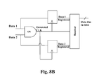
- FIG. 7 is a simplified circuit diagram of a cell information storage circuit of the embodiment of FIG. 3 , wherein the cell information storage circuit is arranged to permit bi-directional communication between the supervisor and the cell information storage circuit, and wherein the cell information storage circuit uses synchronous event driven communication by regenerating the system clock from the two data inputs (as shown in FIGS. 8A and 8B ).
- FIG. 8A illustrate exemplary voltage waveforms for the Data 1 , Data 2 and generated CLK signals applied in the cell information storage circuit of FIG. 7 ;
- FIG. 8B shows a simplified block diagram of a circuit for generating the clock signal of the embodiment of FIG. 7 .
- FIG. 3 there is shown a conventional multi-cell supervisor 20 connected to first 22 to fourth 28 energy storage cells according to an embodiment of the invention.
- reference to an energy storage cell is to be taken to mean a cell as described in the background section above.
- reference to an energy storage cell should be taken to mean the basic energy storage component (i.e. a single energy storage unit that cannot be sub-divided into smaller energy storage units) of a multi-cell energy storage device.
- the first 22 to fourth 28 energy storage cells are connected in series, and each energy storage cell comprises a cell information storage circuit 30 mounted to its housing and connected to the energy storage cell via inductive elements 32 .
- each cell information storage circuit 30 is an integrated circuit which is adapted to store information relating to the energy storage cell it is connected to. Such information includes the cell voltage, a temperature of the energy storage cell, a SoC of the energy storage cell, a SoH of the energy storage cell, and a SoF of the energy storage cell.
- Each energy storage cell therefore comprises an information store which is adapted to store information regarding a parameter of the cell which may be useful for cell administration.
- a cell information storage circuit 30 is also adapted to communicate stored cell information to a conventional multi-cell energy storage device controller using the existing communication interface of the controller.
- the inductive elements 32 are arranged to decouple a cell information storage circuit 30 from it associated energy storage cell during the communication process, otherwise the energy storage cell may cause a short circuit (due to low impedance of the cell) that prevents communication.
- FIG. 4A illustrates a voltage waveform against time for the gate of a transistor Qo of the cell supervisor 20 of FIG. 3 and FIG. 4B illustrates a voltage waveform for the voltage measured at point C of FIG. 3 .
- the average voltage across an inductive coil 32 is zero and hence the average supply voltage of the cell information storage circuit 30 of the first energy storage cell 22 (i.e. the voltage a point C as shown in FIG. 4B ) is equal to the cell voltage of the first energy storage cell 22 .
- the communication pulses driving the transistor Qo are injected on top the cell information storage circuit 30 supply voltage.
- the communication pulses do not interfere with the normal balancing operation of the transistor Qo because switching frequency is high (MHz) with respect to the balancing frequency (mHz), the inductive coil 32 impedance is high during communication with the controller 20 . Therefore, during communication when the inductive coil impedance 32 is high, no substantial charge is removed from the energy storage cell 22 .
- FIG. 5 shows the cell information storage circuit 30 of the first energy storage cell 22 in more detail. As explained above in conjunction with FIG. 3 , the cell information storage circuit 30 is connected to the first energy storage cell 22 via inductive coils 32 , and is connected between two I/O connections of the controller 20 .
- the cell information storage circuit 30 comprises an integrated circuit core 34 having its positive voltage supply Vdd connected to the first I/O connection 36 via a first resistor R 1 , and its negative voltage supply Vss connected to the second I/O connection 38 . Between the positive voltage supply Vdd and the negative voltage supply Vss of the IC core 34 there is connected a first capacitor C 1 .
- the first resistor R 1 and the first capacitor C 1 form a Low Pass Filter (LPF) that removes the communication pulses whilst providing the supply voltage to the IC core 34 .
- LPF Low Pass Filter
- a second capacitor C 2 is connected between the data input (Data) of the IC core 34 , and a second resistor R 2 is connected between the data input (Data) of the IC core 34 and the second I/O connection 38 .
- a clamp diode D 1 is also connected in parallel with the second resistor R 2 .
- the second resistor R 2 and the second capacitor C 2 form a High Pass Filter (HPF) that retrieves the communication pulses with respect to the negative voltage supply Vss connection by using the clamp diode D 1 .
- HPF High Pass Filter
- a transistor switch S 1 is connected between the first I/O connection 36 and the second I/O connection 38 , and the control terminal (e.g. the gate for a MOSFET switch) is connected to the ‘Control’ output terminal of the integrated circuit core 34 .
- FIG. 6 communication from the cell information storage circuit 30 to the cell supervisor 20 is illustrated. This is done by using the Kelvin connections to the cell supervisor 20 .
- the cell information storage circuit 30 uses a load modulation technique by switching the voltage over the transistor switch S 1 (shown in FIGS. 5 and 6 ).
- the inductive coil impedances 32 are significantly high, such that there is no substantial charge removed from the energy storage cell 22 .
- the high impedance of these coils 32 allows bi-directional communication between the cell information storage circuit 30 and the cell supervisor 20 .
- circuit arrangement of FIG. 5 enables communication between the supervisor 20 and the IC core 34 .
- FIG. 7 shows an extension of circuit illustrated in FIG. 5 , wherein the circuit comprises the addition of symmetric inputs from both sides.
- the IC core 34 B has first (Data 1 ) and second (Data 2 ) data inputs, and is arranged in a similar manner to that of FIG. 5 .
- the first data input (Data 1 ) is connected in the same manner as the data input (Data) of the IC core 34 of FIG. 5 .
- a third resistor R 3 and second clamp diode D 2 are connected in parallel between the second resistor R 2 and the second data input (Data 2 ) of the IC core 34 .
- a third capacitor C 3 is connected between the second data input (Data 2 ) of the IC core 34
- a fourth resistor R 4 is connected between the first capacitor C 1 and the second I/O connection 38 .
- the IC core 34 B comprises two data inputs Data 1 and Data 2 for clock signal CLK generation and data retrievals. Both the first (Data 1 ) and second (Data 2 ) data inputs receives different values, e.g. Data 1 expects to receive the ones and Data 2 receives the zeros of the pulse sequences as shown in FIGS. 8A and 8B .
- FIGS. 8A and 8B illustrate the clock signal CLK generation and data extraction, wherein the cell information storage circuit 30 uses synchronous event driven communication by regenerating the system clock signal CLK from the two data inputs Data 1 and Data 2 . Specifically, the clock signal CLK is regenerated by or-ing both data inputs as shown in FIG. 8B .
- embodiment enable the storage of cell information such as cell voltages and temperatures for SoC, SoH and SOF in/at/on the energy storage cell itself.
- Communication between the cell information storage device may be performed using a dedicated 2-way load pulse modulation technique. In this way, the existing I/O interface of a conventional controller can be employed without requiring any modification.
- Embodiments may comprise a cell information storage device linked to each energy storage cell of a multi-cell energy storage device such as a battery pack. Accordingly, embodiments may be used in High Voltage (HV) battery packs (commonly used in the automotive field or electric vehicle), and may permit battery pack maintenance such that the need for replacing the complete battery pack is avoided. This can extend the life cycle of such a HV battery pack.
- HV High Voltage
- a hybrid or electric vehicle may therefore comprise a battery pack comprising a multi-cell energy storage device which has energy storage cells according to an embodiment.
Landscapes
- Engineering & Computer Science (AREA)
- Power Engineering (AREA)
- Manufacturing & Machinery (AREA)
- General Chemical & Material Sciences (AREA)
- Electrochemistry (AREA)
- Chemical Kinetics & Catalysis (AREA)
- Chemical & Material Sciences (AREA)
- Sustainable Energy (AREA)
- Mechanical Engineering (AREA)
- Transportation (AREA)
- Life Sciences & Earth Sciences (AREA)
- Sustainable Development (AREA)
- Microelectronics & Electronic Packaging (AREA)
- Charge And Discharge Circuits For Batteries Or The Like (AREA)
- Secondary Cells (AREA)
Abstract
Description
-
- the “cell” 10 or “battery cell” 10 is the basic energy storage component (i.e. a single energy storage unit that cannot be sub-divided into smaller energy storage units). The voltage is typically 2.5-4.2V, dependent on chemistry and SoC;
- a “section” 12 is a group of
cells 10 that share a number of electronic cell-balancing components. Twosections section 12 b shows theconstituent cells 10. The voltage is typically 5-17V, depending on the number ofcells 10 in the section 12, the cell chemistry and SoC; - a “module” 14 is a group of sections 12. Two
modules module 14 b shows theconstituent sections - a “slice” 16 is a group of series-connected modules that generate the same voltage as the total battery pack. Two
slices slice 16 a shows theconstituent modules
-
- Accurate measurement of cell voltages and temperatures are required by the pack controller for state of charge (SoC), state of health (SoH) and state of function (SoF) determination.
- Safe guarding the over- and under-voltage limits of all cells. If thresholds are exceeded, a hardware fault signal is generated and appropriate action is taken (such as switching-off the pack current, for example)
- Balancing is done to equalize the cell charges and to compensate for leakage differences between cells.
Claims (10)
Applications Claiming Priority (3)
| Application Number | Priority Date | Filing Date | Title |
|---|---|---|---|
| EP12179696.5A EP2696432B1 (en) | 2012-08-08 | 2012-08-08 | Energy storage cell for a multi-cell energy storage device |
| EP12179696.5 | 2012-08-08 | ||
| EP12179696 | 2012-08-08 |
Publications (2)
| Publication Number | Publication Date |
|---|---|
| US20140042957A1 US20140042957A1 (en) | 2014-02-13 |
| US9209477B2 true US9209477B2 (en) | 2015-12-08 |
Family
ID=47018028
Family Applications (1)
| Application Number | Title | Priority Date | Filing Date |
|---|---|---|---|
| US13/938,898 Active 2033-11-25 US9209477B2 (en) | 2012-08-08 | 2013-07-10 | Energy storage cell for a multi-cell energy storage device |
Country Status (3)
| Country | Link |
|---|---|
| US (1) | US9209477B2 (en) |
| EP (1) | EP2696432B1 (en) |
| CN (1) | CN103580091B (en) |
Cited By (1)
| Publication number | Priority date | Publication date | Assignee | Title |
|---|---|---|---|---|
| US10305293B2 (en) | 2014-05-23 | 2019-05-28 | Infineon Technologies Ag | Battery management system |
Families Citing this family (2)
| Publication number | Priority date | Publication date | Assignee | Title |
|---|---|---|---|---|
| US9478779B2 (en) | 2014-08-20 | 2016-10-25 | Ford Global Technologies, Llc | Cell to cell terminal connections for a high voltage battery |
| CN110632489B (en) * | 2019-09-03 | 2021-04-20 | 清华大学 | An IGBT junction temperature monitoring circuit and method based on leakage current |
Citations (14)
| Publication number | Priority date | Publication date | Assignee | Title |
|---|---|---|---|---|
| US6100663A (en) * | 1996-05-03 | 2000-08-08 | Auckland Uniservices Limited | Inductively powered battery charger |
| JP2003077525A (en) | 2001-09-04 | 2003-03-14 | Hitachi Maxell Ltd | Information batteries and mobile devices |
| CN1728317A (en) | 2004-07-20 | 2006-02-01 | 株式会社理光 | Battery pack having a secondary battery and a charging system using the battery pack |
| US7564217B2 (en) | 2004-11-18 | 2009-07-21 | Denso Corporation | Battery pack manager and method of detecting a line cut |
| US7583053B2 (en) | 2005-07-12 | 2009-09-01 | Nissan Motor Co., Ltd. | Battery pack controller with specific battery voltage detection |
| US20100090649A1 (en) * | 2007-04-18 | 2010-04-15 | Pierre Sardat | Engine storage device, particularly for an automobile |
| US20100286938A1 (en) | 2008-02-27 | 2010-11-11 | Nissan Motor Co., Ltd. | Battery pack control apparatus |
| WO2011052594A1 (en) | 2009-10-27 | 2011-05-05 | ミツミ電機株式会社 | Charge/discharge control circuit, semiconductor integrated circuit, charge/discharge control method, and charge/discharge control program |
| EP2385604A1 (en) | 2010-05-07 | 2011-11-09 | Brusa Elektronik AG | Method and cell monitoring unit for monitoring a battery, central monitoring unit and battery |
| US20120057316A1 (en) | 2010-09-03 | 2012-03-08 | Hitachi Vehicle Energy, Ltd. | In-Vehicle Electric Storage Device |
| US20120119705A1 (en) | 2010-11-15 | 2012-05-17 | Martin Eberhard | Control Circuit and Method for Controlling a Plurality of Battery Cells |
| CN202231450U (en) | 2011-08-19 | 2012-05-23 | 陕西斯达煤矿安全装备有限公司 | Charge-discharge control circuit of battery of anti-explosion miner light |
| WO2012067261A1 (en) | 2010-11-19 | 2012-05-24 | ソニー株式会社 | Secondary battery cell, battery pack, and power consumption equipment |
| WO2012070632A1 (en) | 2010-11-26 | 2012-05-31 | ソニー株式会社 | Secondary battery cell, battery pack and power consumption device |
-
2012
- 2012-08-08 EP EP12179696.5A patent/EP2696432B1/en not_active Not-in-force
-
2013
- 2013-05-17 CN CN201310183572.3A patent/CN103580091B/en not_active Expired - Fee Related
- 2013-07-10 US US13/938,898 patent/US9209477B2/en active Active
Patent Citations (19)
| Publication number | Priority date | Publication date | Assignee | Title |
|---|---|---|---|---|
| US6100663A (en) * | 1996-05-03 | 2000-08-08 | Auckland Uniservices Limited | Inductively powered battery charger |
| JP2003077525A (en) | 2001-09-04 | 2003-03-14 | Hitachi Maxell Ltd | Information batteries and mobile devices |
| CN1728317A (en) | 2004-07-20 | 2006-02-01 | 株式会社理光 | Battery pack having a secondary battery and a charging system using the battery pack |
| US7564217B2 (en) | 2004-11-18 | 2009-07-21 | Denso Corporation | Battery pack manager and method of detecting a line cut |
| US7583053B2 (en) | 2005-07-12 | 2009-09-01 | Nissan Motor Co., Ltd. | Battery pack controller with specific battery voltage detection |
| US20100090649A1 (en) * | 2007-04-18 | 2010-04-15 | Pierre Sardat | Engine storage device, particularly for an automobile |
| US20100286938A1 (en) | 2008-02-27 | 2010-11-11 | Nissan Motor Co., Ltd. | Battery pack control apparatus |
| US20120206105A1 (en) | 2009-10-27 | 2012-08-16 | Mitsumi Electric Co., Ltd. | Charge-discharge control circuit, semiconductor integrated circuit, method of controlling charging and discharging, and charging and discharging control program |
| WO2011052594A1 (en) | 2009-10-27 | 2011-05-05 | ミツミ電機株式会社 | Charge/discharge control circuit, semiconductor integrated circuit, charge/discharge control method, and charge/discharge control program |
| EP2385604A1 (en) | 2010-05-07 | 2011-11-09 | Brusa Elektronik AG | Method and cell monitoring unit for monitoring a battery, central monitoring unit and battery |
| US20130106429A1 (en) | 2010-05-07 | 2013-05-02 | Brusa Elektronik Ag | Method and cell monitoring unit for monitoring an accumulator; central monitoring unit and accumulator |
| US20120057316A1 (en) | 2010-09-03 | 2012-03-08 | Hitachi Vehicle Energy, Ltd. | In-Vehicle Electric Storage Device |
| US20120119705A1 (en) | 2010-11-15 | 2012-05-17 | Martin Eberhard | Control Circuit and Method for Controlling a Plurality of Battery Cells |
| WO2012067261A1 (en) | 2010-11-19 | 2012-05-24 | ソニー株式会社 | Secondary battery cell, battery pack, and power consumption equipment |
| JP2012124141A (en) | 2010-11-19 | 2012-06-28 | Sony Corp | Secondary battery cell, battery pack, and power consumption device |
| US20130234721A1 (en) * | 2010-11-19 | 2013-09-12 | Kazuo Nakamura | Secondary battery cell, battery pack, and electricity consumption device |
| WO2012070632A1 (en) | 2010-11-26 | 2012-05-31 | ソニー株式会社 | Secondary battery cell, battery pack and power consumption device |
| JP2012129183A (en) | 2010-11-26 | 2012-07-05 | Sony Corp | Secondary battery cell, battery pack, and electricity consumption device |
| CN202231450U (en) | 2011-08-19 | 2012-05-23 | 陕西斯达煤矿安全装备有限公司 | Charge-discharge control circuit of battery of anti-explosion miner light |
Non-Patent Citations (2)
| Title |
|---|
| Extended European Search Report for EP Patent Appln. No. 12179696.5 (Mar. 4, 2013)xx. |
| WO2012067261 A1, Nakamura et al. May 24, 2012. * |
Cited By (1)
| Publication number | Priority date | Publication date | Assignee | Title |
|---|---|---|---|---|
| US10305293B2 (en) | 2014-05-23 | 2019-05-28 | Infineon Technologies Ag | Battery management system |
Also Published As
| Publication number | Publication date |
|---|---|
| CN103580091A (en) | 2014-02-12 |
| EP2696432A1 (en) | 2014-02-12 |
| CN103580091B (en) | 2016-04-06 |
| EP2696432B1 (en) | 2014-11-19 |
| US20140042957A1 (en) | 2014-02-13 |
Similar Documents
| Publication | Publication Date | Title |
|---|---|---|
| US12074465B2 (en) | Control device, electric storage device, electric storage system, and computer-readable medium | |
| US9270133B2 (en) | Monitoring cells in energy storage system | |
| US10071646B2 (en) | Electrical system and method for operating an electrical system | |
| TW472426B (en) | Battery apparatus and control system therefor | |
| CN103534897B (en) | Battery control device | |
| EP2518860A1 (en) | Battery cell-balancing method and apparatus | |
| CN105034991B (en) | On-board electrical system and method for operating on-board electrical system | |
| CN109690901B (en) | Supercapacitor-based energy storage device | |
| US9160179B2 (en) | Charging apparatus and charging method | |
| US20110316344A1 (en) | Inductive cell balancing | |
| JP6541310B2 (en) | Module control device, balance correction system and storage system | |
| JPWO2013057820A1 (en) | Battery system monitoring device and power storage device including the same | |
| CN108391455A (en) | Electricity accumulating unit and accumulating system | |
| CN104620491A (en) | Battery management system, battery system, motor vehicle and method for generating a periodic alternating voltage | |
| CN102939684A (en) | Cell Balanced Batteries | |
| Pham et al. | A new cell-to-cell fast balancing circuit for lithium-ion batteries in electric vehicles and energy storage system | |
| US20150061597A1 (en) | Battery management system and method | |
| KR20160114677A (en) | Method for operation of an onboard power supply | |
| CN102738853B (en) | Auxiliary battery charging apparatus | |
| Abronzini et al. | Optimal modular bms for high performances nmc battery pack | |
| US9209477B2 (en) | Energy storage cell for a multi-cell energy storage device | |
| EP3337002B1 (en) | Battery system and control unit for a battery system | |
| KR101583694B1 (en) | Battery management system preventing any problems that occur when a signal line is short to the high voltage or ground voltage and control method thereof | |
| US11552482B2 (en) | Hybrid cell balancing for high voltage battery packs | |
| JP7470638B2 (en) | Management system and cell monitoring circuit |
Legal Events
| Date | Code | Title | Description |
|---|---|---|---|
| AS | Assignment |
Owner name: NXP B.V., NETHERLANDS Free format text: ASSIGNMENT OF ASSIGNORS INTEREST;ASSIGNORS:AL-KADI, GHIATH;LAMMERS, MATHEUS JOHANNUS GERARDUS;SIGNING DATES FROM 20130602 TO 20130707;REEL/FRAME:030771/0403 |
|
| AS | Assignment |
Owner name: DATANG NXP SEMICONDUCTORS CO., LTD., CHINA Free format text: ASSIGNMENT OF ASSIGNORS INTEREST;ASSIGNOR:NXP B.V.;REEL/FRAME:033068/0960 Effective date: 20140416 |
|
| STCF | Information on status: patent grant |
Free format text: PATENTED CASE |
|
| AS | Assignment |
Owner name: MORGAN STANLEY SENIOR FUNDING, INC., MARYLAND Free format text: SECURITY AGREEMENT SUPPLEMENT;ASSIGNOR:NXP B.V.;REEL/FRAME:038017/0058 Effective date: 20160218 |
|
| AS | Assignment |
Owner name: MORGAN STANLEY SENIOR FUNDING, INC., MARYLAND Free format text: CORRECTIVE ASSIGNMENT TO CORRECT THE REMOVE APPLICATION 12092129 PREVIOUSLY RECORDED ON REEL 038017 FRAME 0058. ASSIGNOR(S) HEREBY CONFIRMS THE SECURITY AGREEMENT SUPPLEMENT;ASSIGNOR:NXP B.V.;REEL/FRAME:039361/0212 Effective date: 20160218 |
|
| AS | Assignment |
Owner name: NXP B.V., NETHERLANDS Free format text: PATENT RELEASE;ASSIGNOR:MORGAN STANLEY SENIOR FUNDING, INC.;REEL/FRAME:039707/0471 Effective date: 20160805 |
|
| AS | Assignment |
Owner name: MORGAN STANLEY SENIOR FUNDING, INC., MARYLAND Free format text: CORRECTIVE ASSIGNMENT TO CORRECT THE REMOVE APPLICATION 12681366 PREVIOUSLY RECORDED ON REEL 039361 FRAME 0212. ASSIGNOR(S) HEREBY CONFIRMS THE SECURITY AGREEMENT SUPPLEMENT;ASSIGNOR:NXP B.V.;REEL/FRAME:042762/0145 Effective date: 20160218 Owner name: MORGAN STANLEY SENIOR FUNDING, INC., MARYLAND Free format text: CORRECTIVE ASSIGNMENT TO CORRECT THE REMOVE APPLICATION 12681366 PREVIOUSLY RECORDED ON REEL 038017 FRAME 0058. ASSIGNOR(S) HEREBY CONFIRMS THE SECURITY AGREEMENT SUPPLEMENT;ASSIGNOR:NXP B.V.;REEL/FRAME:042985/0001 Effective date: 20160218 |
|
| MAFP | Maintenance fee payment |
Free format text: PAYMENT OF MAINTENANCE FEE, 4TH YEAR, LARGE ENTITY (ORIGINAL EVENT CODE: M1551); ENTITY STATUS OF PATENT OWNER: LARGE ENTITY Year of fee payment: 4 |
|
| AS | Assignment |
Owner name: NXP B.V., NETHERLANDS Free format text: RELEASE BY SECURED PARTY;ASSIGNOR:MORGAN STANLEY SENIOR FUNDING, INC.;REEL/FRAME:050745/0001 Effective date: 20190903 |
|
| AS | Assignment |
Owner name: MORGAN STANLEY SENIOR FUNDING, INC., MARYLAND Free format text: CORRECTIVE ASSIGNMENT TO CORRECT THE REMOVE APPLICATION 12298143 PREVIOUSLY RECORDED ON REEL 042762 FRAME 0145. ASSIGNOR(S) HEREBY CONFIRMS THE SECURITY AGREEMENT SUPPLEMENT;ASSIGNOR:NXP B.V.;REEL/FRAME:051145/0184 Effective date: 20160218 Owner name: MORGAN STANLEY SENIOR FUNDING, INC., MARYLAND Free format text: CORRECTIVE ASSIGNMENT TO CORRECT THE REMOVE APPLICATION 12298143 PREVIOUSLY RECORDED ON REEL 039361 FRAME 0212. ASSIGNOR(S) HEREBY CONFIRMS THE SECURITY AGREEMENT SUPPLEMENT;ASSIGNOR:NXP B.V.;REEL/FRAME:051029/0387 Effective date: 20160218 Owner name: MORGAN STANLEY SENIOR FUNDING, INC., MARYLAND Free format text: CORRECTIVE ASSIGNMENT TO CORRECT THE REMOVE APPLICATION 12298143 PREVIOUSLY RECORDED ON REEL 042985 FRAME 0001. ASSIGNOR(S) HEREBY CONFIRMS THE SECURITY AGREEMENT SUPPLEMENT;ASSIGNOR:NXP B.V.;REEL/FRAME:051029/0001 Effective date: 20160218 Owner name: MORGAN STANLEY SENIOR FUNDING, INC., MARYLAND Free format text: CORRECTIVE ASSIGNMENT TO CORRECT THE REMOVE APPLICATION 12298143 PREVIOUSLY RECORDED ON REEL 038017 FRAME 0058. ASSIGNOR(S) HEREBY CONFIRMS THE SECURITY AGREEMENT SUPPLEMENT;ASSIGNOR:NXP B.V.;REEL/FRAME:051030/0001 Effective date: 20160218 Owner name: MORGAN STANLEY SENIOR FUNDING, INC., MARYLAND Free format text: CORRECTIVE ASSIGNMENT TO CORRECT THE REMOVE APPLICATION12298143 PREVIOUSLY RECORDED ON REEL 039361 FRAME 0212. ASSIGNOR(S) HEREBY CONFIRMS THE SECURITY AGREEMENT SUPPLEMENT;ASSIGNOR:NXP B.V.;REEL/FRAME:051029/0387 Effective date: 20160218 Owner name: MORGAN STANLEY SENIOR FUNDING, INC., MARYLAND Free format text: CORRECTIVE ASSIGNMENT TO CORRECT THE REMOVE APPLICATION12298143 PREVIOUSLY RECORDED ON REEL 042985 FRAME 0001. ASSIGNOR(S) HEREBY CONFIRMS THE SECURITY AGREEMENT SUPPLEMENT;ASSIGNOR:NXP B.V.;REEL/FRAME:051029/0001 Effective date: 20160218 Owner name: MORGAN STANLEY SENIOR FUNDING, INC., MARYLAND Free format text: CORRECTIVE ASSIGNMENT TO CORRECT THE REMOVE APPLICATION12298143 PREVIOUSLY RECORDED ON REEL 042762 FRAME 0145. ASSIGNOR(S) HEREBY CONFIRMS THE SECURITY AGREEMENT SUPPLEMENT;ASSIGNOR:NXP B.V.;REEL/FRAME:051145/0184 Effective date: 20160218 |
|
| MAFP | Maintenance fee payment |
Free format text: PAYMENT OF MAINTENANCE FEE, 8TH YEAR, LARGE ENTITY (ORIGINAL EVENT CODE: M1552); ENTITY STATUS OF PATENT OWNER: LARGE ENTITY Year of fee payment: 8 |
|
| FEPP | Fee payment procedure |
Free format text: ENTITY STATUS SET TO SMALL (ORIGINAL EVENT CODE: SMAL); ENTITY STATUS OF PATENT OWNER: SMALL ENTITY |