US9205818B2 - Brake system and method for controlling a vehicle brake - Google Patents
Brake system and method for controlling a vehicle brake Download PDFInfo
- Publication number
- US9205818B2 US9205818B2 US12/999,948 US99994809A US9205818B2 US 9205818 B2 US9205818 B2 US 9205818B2 US 99994809 A US99994809 A US 99994809A US 9205818 B2 US9205818 B2 US 9205818B2
- Authority
- US
- United States
- Prior art keywords
- brake
- actuators
- sensor
- signal
- control unit
- Prior art date
- Legal status (The legal status is an assumption and is not a legal conclusion. Google has not performed a legal analysis and makes no representation as to the accuracy of the status listed.)
- Expired - Fee Related, expires
Links
- 238000000034 method Methods 0.000 title claims description 18
- 230000003213 activating effect Effects 0.000 claims 2
- 230000002457 bidirectional effect Effects 0.000 claims 2
- 238000012795 verification Methods 0.000 claims 1
- 238000011161 development Methods 0.000 description 3
- 230000018109 developmental process Effects 0.000 description 3
- 230000001960 triggered effect Effects 0.000 description 3
- 238000004891 communication Methods 0.000 description 2
- 230000001133 acceleration Effects 0.000 description 1
- 230000004913 activation Effects 0.000 description 1
- 238000001994 activation Methods 0.000 description 1
- 230000008878 coupling Effects 0.000 description 1
- 238000010168 coupling process Methods 0.000 description 1
- 238000005859 coupling reaction Methods 0.000 description 1
- 230000002349 favourable effect Effects 0.000 description 1
Images


Classifications
-
- B—PERFORMING OPERATIONS; TRANSPORTING
- B60—VEHICLES IN GENERAL
- B60T—VEHICLE BRAKE CONTROL SYSTEMS OR PARTS THEREOF; BRAKE CONTROL SYSTEMS OR PARTS THEREOF, IN GENERAL; ARRANGEMENT OF BRAKING ELEMENTS ON VEHICLES IN GENERAL; PORTABLE DEVICES FOR PREVENTING UNWANTED MOVEMENT OF VEHICLES; VEHICLE MODIFICATIONS TO FACILITATE COOLING OF BRAKES
- B60T8/00—Arrangements for adjusting wheel-braking force to meet varying vehicular or ground-surface conditions, e.g. limiting or varying distribution of braking force
- B60T8/32—Arrangements for adjusting wheel-braking force to meet varying vehicular or ground-surface conditions, e.g. limiting or varying distribution of braking force responsive to a speed condition, e.g. acceleration or deceleration
- B60T8/321—Arrangements for adjusting wheel-braking force to meet varying vehicular or ground-surface conditions, e.g. limiting or varying distribution of braking force responsive to a speed condition, e.g. acceleration or deceleration deceleration
- B60T8/3255—Systems in which the braking action is dependent on brake pedal data
- B60T8/327—Pneumatic systems
-
- B—PERFORMING OPERATIONS; TRANSPORTING
- B60—VEHICLES IN GENERAL
- B60T—VEHICLE BRAKE CONTROL SYSTEMS OR PARTS THEREOF; BRAKE CONTROL SYSTEMS OR PARTS THEREOF, IN GENERAL; ARRANGEMENT OF BRAKING ELEMENTS ON VEHICLES IN GENERAL; PORTABLE DEVICES FOR PREVENTING UNWANTED MOVEMENT OF VEHICLES; VEHICLE MODIFICATIONS TO FACILITATE COOLING OF BRAKES
- B60T7/00—Brake-action initiating means
- B60T7/02—Brake-action initiating means for personal initiation
- B60T7/04—Brake-action initiating means for personal initiation foot actuated
- B60T7/042—Brake-action initiating means for personal initiation foot actuated by electrical means, e.g. using travel or force sensors
-
- B—PERFORMING OPERATIONS; TRANSPORTING
- B60—VEHICLES IN GENERAL
- B60T—VEHICLE BRAKE CONTROL SYSTEMS OR PARTS THEREOF; BRAKE CONTROL SYSTEMS OR PARTS THEREOF, IN GENERAL; ARRANGEMENT OF BRAKING ELEMENTS ON VEHICLES IN GENERAL; PORTABLE DEVICES FOR PREVENTING UNWANTED MOVEMENT OF VEHICLES; VEHICLE MODIFICATIONS TO FACILITATE COOLING OF BRAKES
- B60T8/00—Arrangements for adjusting wheel-braking force to meet varying vehicular or ground-surface conditions, e.g. limiting or varying distribution of braking force
- B60T8/32—Arrangements for adjusting wheel-braking force to meet varying vehicular or ground-surface conditions, e.g. limiting or varying distribution of braking force responsive to a speed condition, e.g. acceleration or deceleration
- B60T8/321—Arrangements for adjusting wheel-braking force to meet varying vehicular or ground-surface conditions, e.g. limiting or varying distribution of braking force responsive to a speed condition, e.g. acceleration or deceleration deceleration
-
- B—PERFORMING OPERATIONS; TRANSPORTING
- B60—VEHICLES IN GENERAL
- B60T—VEHICLE BRAKE CONTROL SYSTEMS OR PARTS THEREOF; BRAKE CONTROL SYSTEMS OR PARTS THEREOF, IN GENERAL; ARRANGEMENT OF BRAKING ELEMENTS ON VEHICLES IN GENERAL; PORTABLE DEVICES FOR PREVENTING UNWANTED MOVEMENT OF VEHICLES; VEHICLE MODIFICATIONS TO FACILITATE COOLING OF BRAKES
- B60T2220/00—Monitoring, detecting driver behaviour; Signalling thereof; Counteracting thereof
- B60T2220/04—Pedal travel sensor, stroke sensor; Sensing brake request
-
- B—PERFORMING OPERATIONS; TRANSPORTING
- B60—VEHICLES IN GENERAL
- B60T—VEHICLE BRAKE CONTROL SYSTEMS OR PARTS THEREOF; BRAKE CONTROL SYSTEMS OR PARTS THEREOF, IN GENERAL; ARRANGEMENT OF BRAKING ELEMENTS ON VEHICLES IN GENERAL; PORTABLE DEVICES FOR PREVENTING UNWANTED MOVEMENT OF VEHICLES; VEHICLE MODIFICATIONS TO FACILITATE COOLING OF BRAKES
- B60T2270/00—Further aspects of brake control systems not otherwise provided for
- B60T2270/40—Failsafe aspects of brake control systems
- B60T2270/402—Back-up
-
- B—PERFORMING OPERATIONS; TRANSPORTING
- B60—VEHICLES IN GENERAL
- B60T—VEHICLE BRAKE CONTROL SYSTEMS OR PARTS THEREOF; BRAKE CONTROL SYSTEMS OR PARTS THEREOF, IN GENERAL; ARRANGEMENT OF BRAKING ELEMENTS ON VEHICLES IN GENERAL; PORTABLE DEVICES FOR PREVENTING UNWANTED MOVEMENT OF VEHICLES; VEHICLE MODIFICATIONS TO FACILITATE COOLING OF BRAKES
- B60T2270/00—Further aspects of brake control systems not otherwise provided for
- B60T2270/40—Failsafe aspects of brake control systems
- B60T2270/404—Brake-by-wire or X-by-wire failsafe
-
- B—PERFORMING OPERATIONS; TRANSPORTING
- B60—VEHICLES IN GENERAL
- B60T—VEHICLE BRAKE CONTROL SYSTEMS OR PARTS THEREOF; BRAKE CONTROL SYSTEMS OR PARTS THEREOF, IN GENERAL; ARRANGEMENT OF BRAKING ELEMENTS ON VEHICLES IN GENERAL; PORTABLE DEVICES FOR PREVENTING UNWANTED MOVEMENT OF VEHICLES; VEHICLE MODIFICATIONS TO FACILITATE COOLING OF BRAKES
- B60T2270/00—Further aspects of brake control systems not otherwise provided for
- B60T2270/82—Brake-by-Wire, EHB
Definitions
- the present invention relates to a brake system and to a method for controlling a vehicle brake.
- German patent document DE 103 57 373 B4 discusses an electronic brake system for a vehicle having at least two brake circuits, which has a braking request recording device having two autonomous braking request recording means, one of which is connected to a central control unit while the other is connected to an autonomous brake circuit control system that is independent of the central electronic control unit.
- the brake circuit control system in cooperation with the one braking request recording means assumes all activations of the vehicle brakes.
- the braking request recording means are sensors integrated into a brake pedal unit. This creates a certain redundancy.
- German patent document DE 19815440 A1 refers to providing for a braking value sensor and a part of a control electronics of a vehicle brake system to be combined into one unit.
- An objective of the exemplary embodiments and/or exemplary methods of the present invention is to improve the brake system and the method of the kind mentioned at the outset in such a way that a greater reliability is ensured even in the event of a failure of the central electronic control unit.
- One aspect of the exemplary embodiments and/or exemplary methods of the present invention is to use, in addition to an “intelligent” central electronic control unit, at least one intelligent sensor and intelligent actuators.
- Intelligent in this sense means that the sensor and actuators contain autonomous electronic processing units including software that are independent of the central electronic control unit.
- the intelligent sensor independently calculates actuating signals for the actuators.
- the actuators for their part verify whether the actuating signal from the central electronic control unit is valid or not. If the actuating signal is valid, then the brake is controlled by it, i.e. by the central electronic control unit. If it is invalid, on the contrary, then the actuating signal ascertained by the intelligent sensor is used to control the brake.
- Both mentioned actuating signals from the central electronic control unit and from the intelligent sensor may be distributed via a network or two separate networks, the brake pedal unit, the central electronic control unit and the actuators being able to communicate bidirectionally via the network.
- the brake pedal unit and the actuators likewise communicate bidirectionally with each other and thus form a system that is redundant with respect to the central electronic control unit.
- the brake pedal unit and the actuators of course are also able to read in and process signals from additional sensors, for example from wheel speed sensors, pressure sensors, roll angle sensors, transversal acceleration sensors, axle load sensors, steering angle sensors etc.
- a third fallback level may be additionally implemented by a purely pneumatic brake control system.
- the brake pedal unit contains customary, purely pneumatic control valves, the intelligent actuators automatically switching to a purely pneumatic control system in the event of a failure of the entire electronic system.
- the brake pedal unit has two sensors.
- One of these may in turn be equipped with an intelligence of its own, while the other is a purely passive sensor, for example a potentiometer or another position sensor for the position of the brake pedal.
- the signal of this non-intelligent sensor is supplied to the (intelligent) central electronic control unit and from there is processed into an actuating signal.
- FIG. 1 shows an exemplary embodiment of a pedal unit of the brake system.
- FIG. 2 shows another exemplary embodiment of a pedal unit of the brake system.
- FIG. 3 shows another exemplary embodiment of a pedal unit of the brake system.
- FIG. 4 shows a first exemplary embodiment of a brake system according to the present invention.
- FIG. 5 shows a brake system according to a second exemplary embodiment of the present invention.
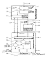
- FIG. 6 shows a flow chart for explaining the principle of operation of a brake system as shown in FIG. 4 having a brake pedal unit as shown in FIG. 1 .
- FIG. 7 shows a flow chart of a brake system as shown in FIG. 5 having a brake pedal unit as shown in FIG. 2 .
- FIG. 1 shows a brake pedal unit 2 , which has a pneumatic control valve 3 and a sensor 4 , which is connected to a brake pedal 6 and which senses its position or movement.
- Sensor 4 is equipped with an intelligence of its own, i.e. it contains electronics that process the output signals of sensor elements, as will be explained further below. Electrical and pneumatic connectors of brake pedal unit 2 are left out for the purpose of clarity.
- Such a brake pedal unit is also suitable for example for a brake system according to the DE 103 57 373 84 document mentioned at the outset.
- FIG. 2 shows a brake pedal unit 2 having two redundant sensors 4 and 5 , of which sensor 4 in turn has an intelligence of its own in the form of an electronic circuit, while sensor 5 has no intelligence of its own.
- a brake pedal unit may be used for a “brake-by-wire” system.
- Brake pedal unit 2 of FIG. 3 has two redundant sensors 4 , which respectively have an intelligence of their own and are likewise connected to brake pedal 6 .
- brake pedal unit 2 thus has two electrical outputs that are independent of each other.
- FIG. 9 shows a brake system according to a first exemplary embodiment of the present invention, in which a brake pedal unit 2 as shown in FIG. 1 is used.
- Brake system 1 of FIG. 9 has a brake pedal unit 2 according to the exemplary embodiment of FIG. 1 with the requirement that brake pedal unit 2 has two pneumatic control valves 3 . 1 and 3 . 2 and one intelligent sensor 4 .
- Control valves 3 . 1 and 3 . 2 are connected respectively via a pneumatic line 7 . 1 and 7 . 2 to separate pressure reservoirs 8 . 1 and 8 . 2 , respectively.
- Pneumatic control valve 3 . 1 is connected via a pneumatic line 7 . 1 to control valves 9 . 1 and 9 . 2 for brake actuators 10 . 1 and 10 . 2 of the wheels of the rear axle of the vehicle.
- Control valve 3 . 2 is connected via a pneumatic line 7 . 2 to control valves 11 . 1 and 11 . 2 for brake actuators 12 . 1 and 12 . 2 of the brakes of the front axle of the vehicle.
- the brake system thus has two separate brake circuits for the brakes of the rear axle and the front axle.
- brake actuators 10 . 1 and 14 . 2 are pneumatically actuated spring-loaded brakes.
- the intelligent sensor 4 of brake pedal unit 2 is connected via an electrical line 13 to a central electronic control unit 14 , which is connected via electrical lines 15 . 1 through 15 . 4 to control valves 9 . 1 , 9 . 2 , 11 . 1 and 11 . 2 .
- Electrical lines 13 and 15 . 1 through 15 . 4 form a network 16 , which allows both for communication between intelligent sensor 4 and central electronic control unit 14 as well as for a direct communication between intelligent sensor 4 and control valves 9 . 1 , 9 . 2 , 11 . 1 and 11 . 2 as well as of course between central electronic control unit 14 and the mentioned control units 9 . 1 , 9 . 2 , 11 . 1 and 11 . 2 .
- Control valves 9 . 1 , 9 . 2 , 11 . 1 and 11 . 2 likewise have an intelligence of their own and may be controlled pneumatically via pneumatic lines 7 . 1 and 7 . 2 or electrically via electrical lines 15 . 1 through 15 . 4 .
- Intelligent sensor 4 supplies the braking request signal triggered by the driver by actuating brake pedal 6 via electrical line 13 to network 16 .
- This signal is received both by central electronic control unit 14 as well as by control valves 9 . 1 , 9 . 2 , 11 . 1 and 11 . 2 .
- a pneumatic signal is conducted from the two pneumatic control valves 3 . 1 and 3 . 2 via pneumatic lines 7 . 1 and 7 . 2 to the control valves.
- brake actuators 10 . 1 , 10 . 2 and 12 . 1 , 12 . 2 are controlled in three different manners.
- Intelligent sensor 4 ascertains the movement or position of brake pedal 6 , which is proportional to the braking request initiated by the driver. This signal is already preprocessed by intelligent sensor 4 into a braking request signal on the basis of a separate software and separate electronics in intelligent sensor 4 by taking into account additional parameters of the vehicle and possibly additional signals from other sensors, which are not represented here. Intelligent sensor 4 calculates an actuation request on the basis of predefined characteristics or on the basis of characteristics that are transmitted to it from central electronic control unit 14 . These may also be parameters, which are automatically “learned” during one or multiple braking processes, it also being possible to process return signals from control valves 9 . 1 , 9 . 2 , 11 . 1 and 11 . 2 .
- Intelligent control valves 9 . 1 , 9 . 2 , 11 . 1 and 11 . 2 are connected to network 16 , which control the air supply and the pressure in brake actuators 10 . 1 , 10 . 2 , 12 . 1 and 12 . 2 .
- Central electronic control unit 14 contains a processing unit, which ascertains a brake actuating instruction for each of control valves 9 . 1 , 9 . 2 , 11 . 1 and 11 . 2 .
- Intelligent control valves 9 , 11 are able to read the actuating signal from the network and trigger a corresponding pneumatic pressure in actuators 10 . 1 , 10 . 2 , 12 . 1 and 12 . 2 .
- Intelligent sensor 4 detects the movement of brake pedal 6 , the movement or position of which is proportional to the braking request desired by the driver.
- the intelligent sensor converts this signal into an electrical format and transmits it via line 13 to network 16 .
- the format of the signal may be a signal that is proportional to the braking request or it may be a brake actuating signal.
- Control valves 9 , 11 are able to interpret this signal and build up the corresponding pressure.
- Brake pedal unit 2 has the two pneumatic control valves 3 . 1 and 3 . 2 , which provides an air pressure that is proportional to the position of brake pedal 6 .
- This pressure is supplied by pneumatic control valves 3 . 1 and 3 . 2 via lines 7 . 1 and 7 . 2 to control valves 9 . 1 , 9 . 2 , 11 . 1 and 11 . 2 for the brakes of the front and the rear axle.
- This pneumatic pressure then produces corresponding brake pressures in actuators 10 , 12 .
- All three described types of control that is, via central electronic control unit 14 , network 16 and the direct pneumatic control via pneumatic control valves 3 . 1 and 3 . 2 , run parallel in time, the brake system selecting the most favorable system depending on the availability and state of these three systems. This is described in more detail in connection with FIG. 6 .
- FIG. 6 describes the principle of operation of the brake system of FIG. 4 or the method according to the present invention.
- a step S 1 in brake pedal unit 2 , an analog braking request signal is produced by sensors 4 by pressing brake pedal 6 , which is then converted into a digital braking request signal by intelligent sensor 4 in a step S 2 .
- a step S 3 in intelligent sensor 4 , an actuating signal for brake actuators 9 , 11 is precalculated from this digital signal and is transmitted via network 16 directly to control valves 9 . 1 , 9 . 2 , 11 . 1 and 11 . 2 .
- the digital braking request signal of step S 2 is also supplied to central electronic control unit 14 , which calculates an actuating signal in a step S 4 , which is then likewise supplied to the control valves.
- step S 5 the actuating signals from steps S 3 and S 4 are transmitted in parallel to control valves 9 , 11 , where a check is performed in a step S 6 as to whether the actuating signal coming from central electronic control unit 14 and calculated in step S 4 is valid or not.
- This actuating signal coming from central electronic control unit 14 has priority and, if it is valid, is implemented in step S 7 , whereby a brake actuation is triggered, which is based on the actuating signal of central electronic control unit 14 .
- step S 6 it is determined in step S 6 that the actuating signal from step S 4 is invalid, then a check is performed in a step S 8 as to whether the actuating signal calculated by the intelligent sensor in step S 3 is valid. If this is the case, then a brake actuation is triggered in step S 9 , which is based on the actuating signal ascertained by intelligent sensor 4 in step S 3 .
- step S 10 a purely pneumatic braking action is initiated as a third fallback level in step S 10 , on the basis of the pneumatic pressured coming from pneumatic control valves 3 . 1 and 3 . 2 .
- Central electronic control unit 14 has first priority
- intelligent sensor 4 has second priority
- the purely pneumatic braking action has third priority.
- influence variables may of course be taken into account, which are either predefined in a vehicle-specific manner and stored in the software or are ascertained by sensors (not shown) and transmitted via network 16 to intelligent units 4 , 14 , 9 and 11 .
- influence variables such as axle load distribution, lockup danger, coupling force between a tractor and a trailer and other variables influencing the stability of a vehicle may be taken into account.
- FIG. 5 shows a second exemplary embodiment of the brake system according to the present invention.
- brake pedal unit 2 is developed in accordance with the exemplary embodiment of FIG. 2 and has two types of sensors, that is, an intelligent sensor 4 and a sensor 5 without an intelligence of its own.
- Sensor 5 is connected via a line 17 to central electronic control unit 14
- intelligent sensor 4 is connected to network 19 .
- Additional sensors 23 may be connected to sensor 4 , which supply sensor 4 with vehicle-specific or driving dynamics-specific measured variables.
- the electrical lines of network 19 are represented as dashed lines, while the electrical lines of network 18 connected to central control unit 14 are represented as solid lines.
- the brake actuators are actuated purely electrically and are in turn equipped with an intelligence of their own.
- Brake actuators 20 . 1 and 20 . 2 for the front axle and 21 . 1 and 21 . 2 for the rear axle are respectively connected to the two networks 18 and 19 , that is, ultimately to central electronic control unit 14 and intelligent sensor 4 .
- intelligent brake actuators 20 and 21 decide whether to execute instructions coming from control unit 14 via network 18 or from intelligent sensor 4 via network 19 , while here too the instructions coming from control unit 14 via network 18 have priority and the instructions coming from intelligent sensor 4 via network 19 are used as a fallback level.
- brake pedal unit 2 has the two sensors 4 and 5 .
- intelligent sensor 4 performs steps S 1 , S 2 and S 3 , which are then supplied via network 19 to brake actuators 20 , 21 .
- non-intelligent sensor 5 produces an electrical braking request signal in step S 11 , which possibly in step S 12 is still converted as a digital signal, it being necessary in this case that non-intelligent sensor 5 directly produces a digital output signal.
- step S 4 calculates an actuating signal for the brake actuators in the same manner as in the first exemplary embodiment.
- additional input variables are taken into account in a manner known per se.
- the actuating signal is supplied via network 18 to the individual brake actuators 20 , 21 .
- step S 5 There the signals applied on networks 18 and 19 are received in step S 5 and again a check is performed in step S 6 as to whether the signal coming from central electronic control unit 14 is valid. If this is the case, then this actuating signal is supplied to actuators 20 and 21 in step S 7 . If, on the contrary, the signal coming from central electronic control unit 14 is invalid, then the signal coming from intelligent sensor 4 via network 19 is selected and supplied to the actuators in step S 9 .
- talk of “the signal” may also refer to multiple signals since different actuating signals may be supplied to the individual actuators, for example for taking into account a braking force distribution in accordance with the axle loads, driving dynamics control, lockup protection etc.
- FIGS. 5 and 7 may also be modified in such a way that a brake pedal unit 2 as shown in FIG. 3 having two intelligent sensors may be used. The one sensor is then connected to central electronic control unit 14 and the other is connected to network 19 .
Landscapes
- Engineering & Computer Science (AREA)
- Transportation (AREA)
- Mechanical Engineering (AREA)
- Regulating Braking Force (AREA)
- Braking Systems And Boosters (AREA)
Abstract
Description
Claims (12)
Applications Claiming Priority (4)
| Application Number | Priority Date | Filing Date | Title |
|---|---|---|---|
| DE102008029311.3 | 2008-06-20 | ||
| DE102008029311A DE102008029311A1 (en) | 2008-06-20 | 2008-06-20 | Brake system and method for controlling a vehicle brake |
| DE102008029311 | 2008-06-20 | ||
| PCT/EP2009/004160 WO2009152981A1 (en) | 2008-06-20 | 2009-06-10 | Brake system and method for controlling a vehicle brake |
Publications (2)
| Publication Number | Publication Date |
|---|---|
| US20110125381A1 US20110125381A1 (en) | 2011-05-26 |
| US9205818B2 true US9205818B2 (en) | 2015-12-08 |
Family
ID=41063079
Family Applications (1)
| Application Number | Title | Priority Date | Filing Date |
|---|---|---|---|
| US12/999,948 Expired - Fee Related US9205818B2 (en) | 2008-06-20 | 2009-06-10 | Brake system and method for controlling a vehicle brake |
Country Status (3)
| Country | Link |
|---|---|
| US (1) | US9205818B2 (en) |
| DE (1) | DE102008029311A1 (en) |
| WO (1) | WO2009152981A1 (en) |
Cited By (3)
| Publication number | Priority date | Publication date | Assignee | Title |
|---|---|---|---|---|
| US20150330853A1 (en) * | 2014-05-16 | 2015-11-19 | Bayerische Motoren Werke Aktiengesellschaft | System and Method for Measurement and Evaluation of Brake Pedal Performance |
| US11634109B2 (en) | 2017-08-17 | 2023-04-25 | Zf Cv Systems Europe Bv | Method for decelerating a vehicle, in particular a commercial vehicle, electro-pneumatic brake system for decelerating a vehicle, and vehicle having an electro-pneumatic brake system |
| US12227161B2 (en) | 2022-02-24 | 2025-02-18 | Deere & Company | Brake pedal feedback system |
Families Citing this family (24)
| Publication number | Priority date | Publication date | Assignee | Title |
|---|---|---|---|---|
| US8423256B2 (en) * | 2009-12-23 | 2013-04-16 | Goodrich Corporation | Systems and methods for adaptive deceleration |
| DE102010021909A1 (en) * | 2010-05-28 | 2011-12-01 | Knorr-Bremse Systeme für Nutzfahrzeuge GmbH | Method for controlling a brake system of a vehicle with electronically controlled Hinterachsbremskreis and pneumatically controlled Vorderachsbremskreis |
| DE102012003106C5 (en) | 2012-02-16 | 2022-01-27 | Knorr-Bremse Systeme für Nutzfahrzeuge GmbH | Method for determining a brake pressure value using characteristic curves |
| ITTO20130307A1 (en) | 2013-04-17 | 2014-10-18 | Itt Italia Srl | METHOD TO REALIZE A BRAKE ELEMENT, IN PARTICULAR A BRAKE PAD, SENSORIZED, SENSORED BRAKE PAD, VEHICLE BRAKE SYSTEM AND ASSOCIATED METHOD |
| US9428242B2 (en) | 2014-02-24 | 2016-08-30 | Harley-Davidson Motor Company Group, LLC | Variable ride height systems and methods |
| DE102014112015A1 (en) * | 2014-08-22 | 2016-02-25 | Knorr-Bremse Systeme für Nutzfahrzeuge GmbH | Method for controlling a operated by a service brake valve device service brake device and service brake device |
| DE102014112014A1 (en) | 2014-08-22 | 2016-02-25 | Knorr-Bremse Systeme für Nutzfahrzeuge GmbH | Method for controlling a service brake device of a vehicle and service brake valve device for such a service brake device |
| US9939035B2 (en) | 2015-05-28 | 2018-04-10 | Itt Italia S.R.L. | Smart braking devices, systems, and methods |
| ITUB20153706A1 (en) | 2015-09-17 | 2017-03-17 | Itt Italia Srl | BRAKING DEVICE FOR HEAVY VEHICLE AND METHOD OF PREVENTING BRAKE OVERHEATING IN A HEAVY VEHICLE |
| ITUB20153709A1 (en) | 2015-09-17 | 2017-03-17 | Itt Italia Srl | DATA ANALYSIS AND MANAGEMENT DEVICE GENERATED BY A SENSORIZED BRAKE SYSTEM FOR VEHICLES |
| ITUA20161336A1 (en) | 2016-03-03 | 2017-09-03 | Itt Italia Srl | DEVICE AND METHOD FOR IMPROVING THE PERFORMANCE OF A VEHICLE ANTI-LOCK AND ANTI-SLIP SYSTEM |
| DE102016004489A1 (en) | 2016-04-18 | 2017-10-19 | Wabco Gmbh | Driver brake valve, compressed air brake system with the driver's brake valve and method of making the driver's brake valve |
| IT201600077944A1 (en) | 2016-07-25 | 2018-01-25 | Itt Italia Srl | DEVICE FOR DETECTION OF RESIDUAL BRAKING TORQUE IN A VEHICLE EQUIPPED WITH DISC BRAKES |
| DE102017009654A1 (en) | 2017-10-17 | 2019-04-18 | Wabco Gmbh | Brake valve, compressed air brake system with the brake valve and method of making the brake valve |
| KR20190098411A (en) * | 2018-02-14 | 2019-08-22 | 현대자동차주식회사 | Vehicle and controlling method of vehicle |
| IT201900015839A1 (en) | 2019-09-06 | 2021-03-06 | Itt Italia Srl | BRAKE PAD FOR VEHICLES AND ITS PRODUCTION PROCESS |
| EP3808619B1 (en) | 2019-10-18 | 2023-08-09 | Haldex Brake Products Aktiebolag | Autonomously driven vehicle |
| DE102019129153A1 (en) * | 2019-10-29 | 2021-04-29 | Wabco Europe Bvba | Foot brake module of an electropneumatic brake system of a motor vehicle |
| DE102020101524A1 (en) * | 2020-01-23 | 2021-07-29 | Bayerische Motoren Werke Aktiengesellschaft | Electrical / electronic architecture for a motor vehicle with an electronic computing device and with an interface control device, as well as a method |
| IT202000013408A1 (en) | 2020-06-05 | 2021-12-05 | Itt Italia Srl | INTELLIGENT VEHICLE BRAKE PAD AND ITS MANUFACTURING METHOD |
| US20240241003A1 (en) | 2021-05-25 | 2024-07-18 | Itt Italia S.R.L. | A method and a device for estimating residual torque between the braked and braking elements of a vehicle |
| CN114312711B (en) * | 2021-07-22 | 2023-02-03 | 华为数字能源技术有限公司 | Electromechanical braking system and vehicle |
| EP4159558B1 (en) | 2021-09-29 | 2024-05-29 | KNORR-BREMSE Systeme für Nutzfahrzeuge GmbH | Foot brake device for vehicles |
| DE102024004243B4 (en) | 2024-12-12 | 2026-02-05 | Mercedes-Benz Group AG | System for controlling the braking behavior of a vehicle |
Citations (12)
| Publication number | Priority date | Publication date | Assignee | Title |
|---|---|---|---|---|
| DE4022671A1 (en) | 1990-07-17 | 1992-01-23 | Wabco Westinghouse Fahrzeug | ELECTRONIC BRAKE SYSTEM FOR ROAD VEHICLES |
| DE19510525A1 (en) | 1995-03-23 | 1996-09-26 | Bosch Gmbh Robert | Method and device for controlling or regulating the brake system of a vehicle |
| DE19634567A1 (en) | 1996-08-27 | 1998-03-05 | Bosch Gmbh Robert | Electric braking system |
| DE19832167A1 (en) | 1997-11-22 | 1999-05-27 | Itt Mfg Enterprises Inc | Electromechanical braking system for cars |
| DE19853036A1 (en) | 1997-11-22 | 1999-06-02 | Continental Teves Ag & Co Ohg | Electromechanical braking system |
| DE19841335A1 (en) | 1998-02-07 | 1999-08-12 | Itt Mfg Enterprises Inc | Generation of a braking request for the control of the electric braking system |
| EP0949130A2 (en) | 1998-04-07 | 1999-10-13 | WABCO GmbH | Control device for a vehicle brake system |
| US6213567B1 (en) | 1998-02-02 | 2001-04-10 | Siemens Aktiengesellschaft | Brake system for a motor vehicle and method for transmitting data in an electrically controlled brake system for a motor vehicle |
| US6317675B1 (en) | 1997-11-22 | 2001-11-13 | Continental Teves Ag & Co., Ohg | Electromechanical brake system |
| DE10118262A1 (en) | 2001-04-12 | 2002-10-17 | Bosch Gmbh Robert | Electronic braking system for vehicles with control modules adjusting braking forces, has error-tolerant control module for front wheel brakes |
| DE10357373A1 (en) | 2003-12-09 | 2005-07-14 | Knorr-Bremse Systeme für Nutzfahrzeuge GmbH | Electronic brake system for a vehicle |
| DE102005062907B3 (en) | 2005-12-29 | 2007-05-10 | Knorr-Bremse Systeme für Nutzfahrzeuge GmbH | Pressure medium-actuated brake system comprises first and second brake control circuit with two braking force generating device whereby brake actuator has first connection for introducing control signals |
-
2008
- 2008-06-20 DE DE102008029311A patent/DE102008029311A1/en not_active Withdrawn
-
2009
- 2009-06-10 US US12/999,948 patent/US9205818B2/en not_active Expired - Fee Related
- 2009-06-10 WO PCT/EP2009/004160 patent/WO2009152981A1/en not_active Ceased
Patent Citations (17)
| Publication number | Priority date | Publication date | Assignee | Title |
|---|---|---|---|---|
| US5255962A (en) | 1990-07-17 | 1993-10-26 | Wabco Westinghouse Fahrzeugbremsen Gmbh | Electronic brake system for road vehicles |
| DE4022671A1 (en) | 1990-07-17 | 1992-01-23 | Wabco Westinghouse Fahrzeug | ELECTRONIC BRAKE SYSTEM FOR ROAD VEHICLES |
| DE19510525A1 (en) | 1995-03-23 | 1996-09-26 | Bosch Gmbh Robert | Method and device for controlling or regulating the brake system of a vehicle |
| US5954407A (en) | 1995-03-23 | 1999-09-21 | Robert Bosch Gmbh | Process and device for an open-loop control and a closed-loop control of a brake system of a vehicle |
| US5952799A (en) | 1996-08-27 | 1999-09-14 | Robert Bosch Gmbh | Electrical brake system |
| DE19634567A1 (en) | 1996-08-27 | 1998-03-05 | Bosch Gmbh Robert | Electric braking system |
| DE19832167A1 (en) | 1997-11-22 | 1999-05-27 | Itt Mfg Enterprises Inc | Electromechanical braking system for cars |
| DE19853036A1 (en) | 1997-11-22 | 1999-06-02 | Continental Teves Ag & Co Ohg | Electromechanical braking system |
| US6317675B1 (en) | 1997-11-22 | 2001-11-13 | Continental Teves Ag & Co., Ohg | Electromechanical brake system |
| US6213567B1 (en) | 1998-02-02 | 2001-04-10 | Siemens Aktiengesellschaft | Brake system for a motor vehicle and method for transmitting data in an electrically controlled brake system for a motor vehicle |
| DE19841335A1 (en) | 1998-02-07 | 1999-08-12 | Itt Mfg Enterprises Inc | Generation of a braking request for the control of the electric braking system |
| EP0949130A2 (en) | 1998-04-07 | 1999-10-13 | WABCO GmbH | Control device for a vehicle brake system |
| DE19815440A1 (en) | 1998-04-07 | 1999-10-14 | Wabco Gmbh | Control device for a vehicle brake system |
| US6203115B1 (en) | 1998-04-07 | 2001-03-20 | Wabco Gmbh | Control system for a vehicle braking system |
| DE10118262A1 (en) | 2001-04-12 | 2002-10-17 | Bosch Gmbh Robert | Electronic braking system for vehicles with control modules adjusting braking forces, has error-tolerant control module for front wheel brakes |
| DE10357373A1 (en) | 2003-12-09 | 2005-07-14 | Knorr-Bremse Systeme für Nutzfahrzeuge GmbH | Electronic brake system for a vehicle |
| DE102005062907B3 (en) | 2005-12-29 | 2007-05-10 | Knorr-Bremse Systeme für Nutzfahrzeuge GmbH | Pressure medium-actuated brake system comprises first and second brake control circuit with two braking force generating device whereby brake actuator has first connection for introducing control signals |
Non-Patent Citations (2)
| Title |
|---|
| European Patent Office, International Preliminary Report on Patentability and Written Opinion, Jan. 6, 2011, from International Patent Application No. PCT/EP2009/004160, filed on Jun. 10, 2009. |
| European Patent Office, Translation of International Preliminary Report on Patentability and Written Opinion, Jan. 27, 2011, from International Patent Application No. PCT/EP2009/004160, filed on Jun. 10, 2009. |
Cited By (4)
| Publication number | Priority date | Publication date | Assignee | Title |
|---|---|---|---|---|
| US20150330853A1 (en) * | 2014-05-16 | 2015-11-19 | Bayerische Motoren Werke Aktiengesellschaft | System and Method for Measurement and Evaluation of Brake Pedal Performance |
| US9707950B2 (en) * | 2014-05-16 | 2017-07-18 | Bayerische Motoren Werke Aktiengesellschaft | System and method for measurement and evaluation of brake pedal performance |
| US11634109B2 (en) | 2017-08-17 | 2023-04-25 | Zf Cv Systems Europe Bv | Method for decelerating a vehicle, in particular a commercial vehicle, electro-pneumatic brake system for decelerating a vehicle, and vehicle having an electro-pneumatic brake system |
| US12227161B2 (en) | 2022-02-24 | 2025-02-18 | Deere & Company | Brake pedal feedback system |
Also Published As
| Publication number | Publication date |
|---|---|
| US20110125381A1 (en) | 2011-05-26 |
| WO2009152981A1 (en) | 2009-12-23 |
| DE102008029311A1 (en) | 2009-12-31 |
Similar Documents
| Publication | Publication Date | Title |
|---|---|---|
| US9205818B2 (en) | Brake system and method for controlling a vehicle brake | |
| US11046289B2 (en) | System comprising separate control units for the actuation units of an electric parking brake | |
| US11124169B2 (en) | System comprising separate control units for the actuation units of an electric parking brake | |
| CN113677573B (en) | Method for operating a brake system of a vehicle and brake system | |
| CN112739591B (en) | Brake system for a vehicle, vehicle and method of controlling a brake system of a vehicle | |
| EP3626557B1 (en) | Brake system for a vehicle | |
| US9296370B2 (en) | Hydraulic and electronic braking system for autonomous braking | |
| US6349996B1 (en) | Electrically controlled decentralized control system in a vehicle | |
| US20210206374A1 (en) | Brake redundancy concept for highly automated driving | |
| US20210394721A1 (en) | Redundant braking system and method for operating such a braking system | |
| CN108082157A (en) | Line control brake system | |
| US11926305B2 (en) | Method for the automated electronic control of a brake system in a utility vehicle having anti-lock braking protection | |
| EP3626560B1 (en) | Brake system for a vehicle and vehicle | |
| CN110730743A (en) | Modification of wheel trajectories when steering system fails | |
| US11724676B2 (en) | Trailer detection and control module | |
| KR20240125021A (en) | How the brake system works and the brake system | |
| CN112714727B (en) | Brake system for vehicle | |
| US20090230762A1 (en) | Brake System for Motor Vehicles | |
| US7367436B2 (en) | Motor vehicle equipped with a brake system and with a drive system | |
| AU2020309520B2 (en) | Trailer control valve with integrated trailer supply | |
| US6749271B1 (en) | Brake system for vehicles, especially commercial vehicles | |
| US12391230B2 (en) | Dual-control electro-pneumatic foot brake system and method | |
| JP2001270430A (en) | Method for automatically detecting the mounting position of a unit for generating a braking force in an electromagnetic vehicle brake system | |
| JP2002274348A (en) | Automotive brake device and control method therefor | |
| US20250360900A1 (en) | Method for controlling a braking system, and braking system |
Legal Events
| Date | Code | Title | Description |
|---|---|---|---|
| AS | Assignment |
Owner name: KNORR-BREMSE SYSTEME FUER NUTZFAHRZEUGE GMBH, GERM Free format text: ASSIGNMENT OF ASSIGNORS INTEREST;ASSIGNORS:SZELL, PETER;GIANONE, LASZLO;SZABO, GERGELY;SIGNING DATES FROM 20110112 TO 20110113;REEL/FRAME:025748/0814 |
|
| ZAAA | Notice of allowance and fees due |
Free format text: ORIGINAL CODE: NOA |
|
| ZAAB | Notice of allowance mailed |
Free format text: ORIGINAL CODE: MN/=. |
|
| STCF | Information on status: patent grant |
Free format text: PATENTED CASE |
|
| MAFP | Maintenance fee payment |
Free format text: PAYMENT OF MAINTENANCE FEE, 4TH YEAR, LARGE ENTITY (ORIGINAL EVENT CODE: M1551); ENTITY STATUS OF PATENT OWNER: LARGE ENTITY Year of fee payment: 4 |
|
| FEPP | Fee payment procedure |
Free format text: MAINTENANCE FEE REMINDER MAILED (ORIGINAL EVENT CODE: REM.); ENTITY STATUS OF PATENT OWNER: LARGE ENTITY |
|
| LAPS | Lapse for failure to pay maintenance fees |
Free format text: PATENT EXPIRED FOR FAILURE TO PAY MAINTENANCE FEES (ORIGINAL EVENT CODE: EXP.); ENTITY STATUS OF PATENT OWNER: LARGE ENTITY |
|
| STCH | Information on status: patent discontinuation |
Free format text: PATENT EXPIRED DUE TO NONPAYMENT OF MAINTENANCE FEES UNDER 37 CFR 1.362 |
|
| FP | Lapsed due to failure to pay maintenance fee |
Effective date: 20231208 |