US9203677B2 - Signal processing method and associated apparatus - Google Patents
Signal processing method and associated apparatus Download PDFInfo
- Publication number
- US9203677B2 US9203677B2 US13/613,182 US201213613182A US9203677B2 US 9203677 B2 US9203677 B2 US 9203677B2 US 201213613182 A US201213613182 A US 201213613182A US 9203677 B2 US9203677 B2 US 9203677B2
- Authority
- US
- United States
- Prior art keywords
- energy
- starting point
- minimum
- spectral line
- search starting
- Prior art date
- Legal status (The legal status is an assumption and is not a legal conclusion. Google has not performed a legal analysis and makes no representation as to the accuracy of the status listed.)
- Active - Reinstated, expires
Links
Images


Classifications
-
- H—ELECTRICITY
- H04—ELECTRIC COMMUNICATION TECHNIQUE
- H04L—TRANSMISSION OF DIGITAL INFORMATION, e.g. TELEGRAPHIC COMMUNICATION
- H04L27/00—Modulated-carrier systems
- H04L27/26—Systems using multi-frequency codes
- H04L27/2601—Multicarrier modulation systems
- H04L27/2647—Arrangements specific to the receiver only
- H04L27/2655—Synchronisation arrangements
- H04L27/2666—Acquisition of further OFDM parameters, e.g. bandwidth, subcarrier spacing, or guard interval length
-
- H—ELECTRICITY
- H04—ELECTRIC COMMUNICATION TECHNIQUE
- H04L—TRANSMISSION OF DIGITAL INFORMATION, e.g. TELEGRAPHIC COMMUNICATION
- H04L7/00—Arrangements for synchronising receiver with transmitter
- H04L7/02—Speed or phase control by the received code signals, the signals containing no special synchronisation information
- H04L7/027—Speed or phase control by the received code signals, the signals containing no special synchronisation information extracting the synchronising or clock signal from the received signal spectrum, e.g. by using a resonant or bandpass circuit
-
- H—ELECTRICITY
- H04—ELECTRIC COMMUNICATION TECHNIQUE
- H04L—TRANSMISSION OF DIGITAL INFORMATION, e.g. TELEGRAPHIC COMMUNICATION
- H04L27/00—Modulated-carrier systems
- H04L27/0014—Carrier regulation
- H04L2027/0024—Carrier regulation at the receiver end
- H04L2027/0026—Correction of carrier offset
Definitions
- the invention relates in general to a digital television broadcasting technique, and more particularly, to a technique for determining a symbol rate and a carrier frequency offset of a digital television signal.
- digital television broadcasting continues to mature.
- digital television signals can also be transmitted in the form of wireless signals via a base station or a satellite.
- the Digital Video Broadcasting—Satellite (DVB-S) and the Digital Video Broadcasting—Satellite—Second Generation (DVB-S2) are prevalent standards in digital television broadcasting.
- a symbol rate of digital television signals can be an arbitrary value between 0 to 45 MHz, which means the symbol rate can be any value in a wide range. Since a receiver cannot be informed of a carrier channel and a symbol rate selected at the transmitter in advance, the receiver must scan all channels and the entire symbol rate range to correctly decode and restore a received signal. However, the sequential scanning toward all parameter combinations by the receiver is extremely time consuming, and such an approach is not an ideal solution from both efficiency and performance perspectives.
- the invention is directed to a signal processing apparatus and associated method.
- the signal processing apparatus and associated method searches for a minimum energy point of a spectrum according to a predetermined condition, and are capable of eliminating noise regions in the spectrum to further identify the symbol rate and the carrier frequency offset.
- a signal processing apparatus receiving a spectral line corresponding to an original signal, comprises a starting point determining module, a searching module and a symbol rate determining module.
- the starting point determining module finds a maximum energy in the spectral line, and determines at least one search starting point according to the maximum energy.
- the searching module searches from the at least one search starting point along the spectral line towards a region having a lower energy for at least one minimum energy satisfying a predetermined condition.
- the symbol rate determining module determines a symbol rate of the original signal according to the at least one minimum energy.
- a signal processing method receiving a spectral line corresponding to an original signal.
- the signal processing method comprises steps of: determining at least one search starting point by utilizing a maximum energy of the spectral line; searching for at least one minimum energy from the at least one search starting point along the spectral line towards a region having a lower energy, the at least one minimum energy satisfying a predetermined condition; and determining a symbol rate of the original signal according to the at least one minimum energy.
- FIG. 1 is a block diagram of a signal processing apparatus according to one embodiment of the present invention.
- FIGS. 2A to 2C are examples of spectral lines and related dots according to embodiments of the present invention.
- FIG. 3 is a block diagram of a signal processing apparatus further comprising a carrier frequency offset determining module according to another embodiment of the present invention.
- FIG. 4 is a flowchart of a signal processing method according to one embodiment of the present invention.
- FIG. 1 shows a signal processing apparatus 100 according to one embodiment of the present invention.
- the signal processing apparatus 100 comprises a spectrum generating module 12 , a starting point determining module 14 , a searching module 16 and a symbol rate determining module 18 .
- the signal processing module 100 may be integrated in a DVB-S or DVB-S2 compliant digital television signal receiver.
- the spectrum generating module 12 receives and analyzes an original signal to generate a spectral line of the original signal.
- the original signal may be a digital television signal of a particular channel.
- the spectrum generating unit 12 may divide a digital input signal into multiple segments (e.g., 32 segments or 64 segments), perform fast Fourier transform (FFT) and superimpose energy square values of all transform results into a superimposed result. That is, the spectral line is in fact composed of many dots corresponding to different frequencies/energies.
- the spectrum generating unit 12 may further perform a smoothing procedure (e.g., through a moving average circuit) on the superimposed result to filter and remove a portion of the noise in the spectral line.
- FIG. 2A shows an example of a spectral line generated by the spectrum generating unit 12 .
- the starting point determining module 14 first finds a maximum energy ‘max’ and an initial minimum energy ‘min’ in the spectral line, as indicated in FIG. 2B .
- a region demarcated by a dotted line 20 contains energy contributed by noise.
- a result determined and obtained directly based on the maximum energy ‘max’ and the initial minimum energy ‘min’ may contain an error. Details of how the signal processing apparatus 100 prevents such issue of misjudging symbol rate and/or carrier frequency offset due to noise interference are described below.
- the starting point determining module 14 determines at least one search starting point according to the maximum energy max and the initial minimum energy min. For example, the starting point determining module 14 calculates an average ‘avg’ of the maximum energy ‘max’ and the initial minimum energy ‘min’, and identifies from the spectral line two points P 1 and P 2 corresponding to the average avg as the search starting points. In a situation where the initial energy is very small, the average ‘avg’ is approximately a half of the maximum energy ‘max’, i.e., lower than the maximum energy ‘max’ by approximately 3 dB.
- the energy value corresponding to the search starting point is not limited to the average ‘avg’ of the maximum energy ‘max’ and the initial minimum energy ‘min’, and may be any energy value between the maximum energy ‘max’ and the initial minimum energy ‘min’, or even the maximum energy ‘max’ itself.
- the starting point determining module 14 may locate the maximum energy ‘max’ in the spectral line, and utilize at least one point lower than the maximum energy ‘max’ by a predetermined value as a search starting point. In other words, the search starting point is not necessarily selected based on the minimum energy ‘min’. Further, in another embodiment, the starting point determining module 14 may also select either the point P 1 or the point P 2 as the search starting point.
- the searching module 16 After the starting point determining module 14 selects and determines the search starting points P 1 and P 2 , the searching module 16 respectively searches from the search starting points P 1 and P 2 along the spectral line towards a region having a lower energy for at least one minimum energy point satisfying a predetermined condition. Taking the situation in FIG. 2B for example, the searching module 16 searches from the search starting point P 1 towards the left of the spectral line, and searches from the search starting point P 2 towards the right of the spectral line. In another embodiment, assuming that only one search starting point is available, the searching is performed respectively towards the left and right of the spectral line.
- the predetermined condition includes a condition that an absolute value of a slope corresponding to the minimum energy point in the spectral line is smaller than a slope threshold.
- the spectral line in fact includes multiple dots corresponding to different frequencies/energies. With respect to the search from the search starting point P 1 , dots that are more away from the search starting point P 1 have lower energies and thus correspond to smaller slope absolute values.
- the searching module 16 may be designed to select one dot of one of multiple dots as the minimum energy point after finding that the slope absolute value corresponding to the one dot or multiple dots is smaller than a predetermined value. Referring to FIG.
- the searching module 16 finds two minimum energy points P 3 and P 4 respectively corresponding to the search starting points P 1 and P 2 after searching, with the minimum energy points P 3 and P 4 satisfying the predetermined condition adopted by the searching module 16 .
- the energies corresponding to the minimum energy points P 3 and P 4 more approach the real minimum signal energy.
- the searching module 16 may be designed to continuously and selectively update the slope threshold according to a latest search result. Assuming that the horizontal spacings of the dots in the spectral line are equal, the energy difference between each two adjacent dots is equivalently one relative slope.
- the slope threshold may be set as ⁇ MAX /10, where ⁇ MAX represents a currently found maximum energy difference between two dots in searching.
- the searching module 16 modifies the slope threshold ⁇ MAX /10 according to the latest energy difference.
- the predetermined condition adopted by the searching module 16 may be
- the predetermined condition of the searching module 16 may further include a condition that the energy difference between the minimum energy and the maximum energy ‘max’ is greater than an energy threshold.
- the predetermined condition may be both
- the symbol rate determining module 18 determines a symbol rate of the original signal according to the minimum energy points P 3 and P 4 .
- the symbol rate determining module 18 first calculates a frequency difference ⁇ F corresponding to the two minimum energy points P 3 and P 4 , and divides the frequency difference ⁇ F by a roll-off factor to obtain the symbol rate of the original signal.
- the equation is as follows:
- N a computing point from the aforementioned FFT
- N P3 and N P4 respectively represent horizontal coordinates corresponding to the minimum energy points P 3 and P 4
- R represents a sampling frequency of the original signal.
- the above sampling may be performed by the spectrum generating module 12 , or by a front-end receiving circuit disposed in the spectrum generating module 12 .
- the size of the roll-off factor varies depending on different signals or hardware characteristics of the receiving circuit. For example, a range of the roll-off factor may be between 1.2 and 1.5.
- the symbol rate determining module 18 reassesses a modified average energy avg’ according to the maximum energy max and the minimum energy points P 3 and P 4 , and regards a frequency difference between two intersections of the spectral line and the modified average energy avg’ as the symbol rate of the original signal.
- the signal processing apparatus 10 may further comprise a carrier frequency offset (CFO) determining module 19 for determining the carrier frequency offset of the original signal according to the two minimum energy points P 3 and P 4 .
- the carrier frequency offset determining module 19 reassesses the modified average energy avg’ according to the maximum energy max and the minimum energy points P 3 and P 4 , and utilizes the two intersections of the spectral line and the modified average energy avg’ as modified search starting points P 1 ′ and P 2 ′.
- the carrier frequency offset determining module 19 calculates the carrier frequency offset according to the equation below:
- the carrier frequency offset determining module 19 calculates an average frequency corresponding to the two modified search starting points P 1 ′ and P 2 ′, and adopts a difference between the average frequency and a central frequency of the spectrum as the carrier frequency offset of the original signal.
- a subsequent circuit may further be used to fine-tune the symbol rate and/or the carrier frequency offset generated by the signal processing apparatus 100 .
- the signal processing apparatus 100 of the present invention by searching for the minimum energy point having a higher accuracy according to the predetermined condition, eliminates the noise region demarcated by the dotted line 20 to prevent from misjudging symbol rate and carrier frequency offset.
- a signal processing method is provided, as shown in FIG. 4 .
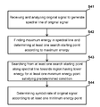
- Step S 41 an original signal is received and analyzed to generate a spectral line of the original signal.
- Step S 42 a maximum energy in the spectral line is found, and at least one search starting point is determined according to the maximum energy.
- Step S 43 from the at least one starting point, searching along the spectral line is performed toward a region having a lower energy for at least one minimum energy point satisfying a predetermined condition.
- a symbol rate of the original signal is determined according to the at least one minimum energy point.
- circuit operation process e.g., the method for determining the search starting point, the predetermined condition for searching the minimum energy point, the method for determining the symbol rate, and the method for determining the carrier frequency offset
- variations in the circuit operation process e.g., the method for determining the search starting point, the predetermined condition for searching the minimum energy point, the method for determining the symbol rate, and the method for determining the carrier frequency offset
- the circuit operation process may also be applied to the signal processing method in FIG. 4 , and details thereof shall be omitted herein.
- FIGS. 1 and 3 may be implemented in hardware or software or a combination thereof.
- Hardware may include one or more electronic processors, associated memory and connection circuitry.
- the hardware may also include, e.g., an application specific integrated circuit (ASIC) configured to perform the functionality described herein.
- ASIC application specific integrated circuit
- the invention provides a signal processing apparatus and associated method.
- the signal processing apparatus and associated method searches for the minimum energy point of the spectrum according to the predetermined condition, and is capable of eliminating the noise region in the spectrum, so as to further identify the reliable symbol rate and carrier frequency offset and sparing possible complications in sequentially scanning different symbol rates.
Abstract
Description
successively occurring for five times, where E(i+1) represents the energy of a next dot, and E(i) represents the energy of the current dot.
and [avg−E(i+1)]>(max−avg)*3/4 successively occurring for five times, where avg represents the previous average energy, and max represents the maximum energy determined by the starting
where N represents a computing point from the aforementioned FFT, NP3 and NP4 respectively represent horizontal coordinates corresponding to the minimum energy points P3 and P4, and R represents a sampling frequency of the original signal. The above sampling may be performed by the
Claims (19)
Applications Claiming Priority (3)
| Application Number | Priority Date | Filing Date | Title |
|---|---|---|---|
| TW101110401 | 2012-03-26 | ||
| TW101110401A | 2012-03-26 | ||
| TW101110401A TWI463845B (en) | 2012-03-26 | 2012-03-26 | Signal processing apparatus and signal processing method |
Publications (2)
| Publication Number | Publication Date |
|---|---|
| US20130253867A1 US20130253867A1 (en) | 2013-09-26 |
| US9203677B2 true US9203677B2 (en) | 2015-12-01 |
Family
ID=49213028
Family Applications (1)
| Application Number | Title | Priority Date | Filing Date |
|---|---|---|---|
| US13/613,182 Active - Reinstated 2034-05-04 US9203677B2 (en) | 2012-03-26 | 2012-09-13 | Signal processing method and associated apparatus |
Country Status (2)
| Country | Link |
|---|---|
| US (1) | US9203677B2 (en) |
| TW (1) | TWI463845B (en) |
Families Citing this family (1)
| Publication number | Priority date | Publication date | Assignee | Title |
|---|---|---|---|---|
| US9532328B2 (en) * | 2013-09-09 | 2016-12-27 | Qualcomm Incorporated | Methods and apparatuses for improving quality of positioning |
Citations (3)
| Publication number | Priority date | Publication date | Assignee | Title |
|---|---|---|---|---|
| WO2010057974A1 (en) | 2008-11-21 | 2010-05-27 | Thomson Licensing | Method and apparatus for locating channels and estimating channel baud rates |
| US20110135042A1 (en) * | 2009-12-08 | 2011-06-09 | Sunplus Technoloy Co., Ltd. | Blind scan system and method in a DVB-S system |
| US8406345B2 (en) * | 2009-11-27 | 2013-03-26 | Sunplus Technology Co., Ltd. | Method and device for aquiring a channel with frequency offset less than half symbol rate |
Family Cites Families (1)
| Publication number | Priority date | Publication date | Assignee | Title |
|---|---|---|---|---|
| US8391345B2 (en) * | 2009-10-14 | 2013-03-05 | Qualcomm Incorporated | Power spectral distribution measurement to facilitate system acquisition |
-
2012
- 2012-03-26 TW TW101110401A patent/TWI463845B/en not_active IP Right Cessation
- 2012-09-13 US US13/613,182 patent/US9203677B2/en active Active - Reinstated
Patent Citations (4)
| Publication number | Priority date | Publication date | Assignee | Title |
|---|---|---|---|---|
| WO2010057974A1 (en) | 2008-11-21 | 2010-05-27 | Thomson Licensing | Method and apparatus for locating channels and estimating channel baud rates |
| US8406345B2 (en) * | 2009-11-27 | 2013-03-26 | Sunplus Technology Co., Ltd. | Method and device for aquiring a channel with frequency offset less than half symbol rate |
| US20110135042A1 (en) * | 2009-12-08 | 2011-06-09 | Sunplus Technoloy Co., Ltd. | Blind scan system and method in a DVB-S system |
| TW201121322A (en) | 2009-12-08 | 2011-06-16 | Sunplus Technology Co Ltd | Blind scan system and method in a DVB-S system |
Non-Patent Citations (1)
| Title |
|---|
| Taiwan Office Action dated Jul. 7, 2014, 6 pages. |
Also Published As
| Publication number | Publication date |
|---|---|
| TWI463845B (en) | 2014-12-01 |
| US20130253867A1 (en) | 2013-09-26 |
| TW201340653A (en) | 2013-10-01 |
Similar Documents
| Publication | Publication Date | Title |
|---|---|---|
| US9131198B2 (en) | Signal processing apparatus and associated method | |
| CN1738302B (en) | Frequency recovery apparatus and mobile broadcast receiver using the frequency recovery apparatus | |
| US20150093995A1 (en) | Transmission Frequency Spectrum Scanning | |
| US10944615B2 (en) | Control apparatus, device and method, signal processing apparatus and method, and mobile terminal | |
| US20150172086A1 (en) | Synchronization and acquisition in radio communication systems | |
| US20080247476A1 (en) | Method and Synchronizer for Fine Ofdm Symbol Synchronization and Method/Receiver for the Reception of Ofdm Symbols | |
| US8090333B2 (en) | Receiving apparatus, receiving method, and program | |
| US9614696B2 (en) | Alternating phase filter for increasing communication speeds, spectral efficiency and enabling other benefits | |
| US20130215950A1 (en) | Apparatus and method for detecting symbol rate | |
| US20120264381A1 (en) | Multi-Standard Transceiver, Device and Method | |
| RU2439827C1 (en) | Reception apparatus, reception method, reception program and system | |
| US9203678B2 (en) | Receiving device, receiving method, program, and receiving system | |
| US20090009396A1 (en) | Method and apparatus for locationing using dvb-t digital television signals | |
| US8238490B2 (en) | Method and circuit for determining a Doppler shift of a signal | |
| US9774484B2 (en) | Receiver controller | |
| US20080273646A1 (en) | Sampling clock offset tracking and symbol re-timing | |
| US20180091241A1 (en) | Transmitter performance calibration systems and methods | |
| US9203677B2 (en) | Signal processing method and associated apparatus | |
| US8275052B2 (en) | FFT carrier frequency offset estimation for OFDM signal | |
| US8804877B2 (en) | Apparatus and method for correcting phase error | |
| US10142150B2 (en) | Pilot signal generating apparatus, method thereof, and transmitting apparatus | |
| JP5272893B2 (en) | AFC circuit and AFC control method for digital radio | |
| JP2006325077A (en) | Sampling clock control method of diversity receiver and diversity receiver | |
| US9948491B2 (en) | Apparatus and method for estimating carrier frequency offset | |
| US9288095B1 (en) | Signal receiving system, band detection method for multi-carrier signal and demodulating apparatus thereof |
Legal Events
| Date | Code | Title | Description |
|---|---|---|---|
| AS | Assignment |
Owner name: MSTAR SEMICONDUCTOR, INC., TAIWAN Free format text: ASSIGNMENT OF ASSIGNORS INTEREST;ASSIGNORS:CHANG, CHU-HSIN;CHENG, KAI-WEN;LIAO, YI-YING;AND OTHERS;REEL/FRAME:028952/0085 Effective date: 20120712 |
|
| STCF | Information on status: patent grant |
Free format text: PATENTED CASE |
|
| FEPP | Fee payment procedure |
Free format text: MAINTENANCE FEE REMINDER MAILED (ORIGINAL EVENT CODE: REM.); ENTITY STATUS OF PATENT OWNER: LARGE ENTITY |
|
| LAPS | Lapse for failure to pay maintenance fees |
Free format text: PATENT EXPIRED FOR FAILURE TO PAY MAINTENANCE FEES (ORIGINAL EVENT CODE: EXP.); ENTITY STATUS OF PATENT OWNER: LARGE ENTITY |
|
| STCH | Information on status: patent discontinuation |
Free format text: PATENT EXPIRED DUE TO NONPAYMENT OF MAINTENANCE FEES UNDER 37 CFR 1.362 |
|
| FP | Lapsed due to failure to pay maintenance fee |
Effective date: 20191201 |
|
| AS | Assignment |
Owner name: MEDIATEK INC., TAIWAN Free format text: MERGER;ASSIGNOR:MSTAR SEMICONDUCTOR, INC.;REEL/FRAME:052871/0833 Effective date: 20190115 |
|
| PRDP | Patent reinstated due to the acceptance of a late maintenance fee |
Effective date: 20200809 |
|
| FEPP | Fee payment procedure |
Free format text: PETITION RELATED TO MAINTENANCE FEES FILED (ORIGINAL EVENT CODE: PMFP); ENTITY STATUS OF PATENT OWNER: LARGE ENTITY Free format text: PETITION RELATED TO MAINTENANCE FEES GRANTED (ORIGINAL EVENT CODE: PMFG); ENTITY STATUS OF PATENT OWNER: LARGE ENTITY Free format text: SURCHARGE, PETITION TO ACCEPT PYMT AFTER EXP, UNINTENTIONAL (ORIGINAL EVENT CODE: M1558); ENTITY STATUS OF PATENT OWNER: LARGE ENTITY |
|
| MAFP | Maintenance fee payment |
Free format text: PAYMENT OF MAINTENANCE FEE, 4TH YEAR, LARGE ENTITY (ORIGINAL EVENT CODE: M1551); ENTITY STATUS OF PATENT OWNER: LARGE ENTITY Year of fee payment: 4 |
|
| STCF | Information on status: patent grant |
Free format text: PATENTED CASE |
|
| AS | Assignment |
Owner name: XUESHAN TECHNOLOGIES INC., CANADA Free format text: ASSIGNMENT OF ASSIGNORS INTEREST;ASSIGNOR:MEDIATEK INC.;REEL/FRAME:056593/0167 Effective date: 20201223 |
|
| MAFP | Maintenance fee payment |
Free format text: PAYMENT OF MAINTENANCE FEE, 8TH YEAR, LARGE ENTITY (ORIGINAL EVENT CODE: M1552); ENTITY STATUS OF PATENT OWNER: LARGE ENTITY Year of fee payment: 8 |