US9189863B2 - Method and system for detecting motion capable of removing shadow by heat - Google Patents
Method and system for detecting motion capable of removing shadow by heat Download PDFInfo
- Publication number
- US9189863B2 US9189863B2 US13/887,480 US201313887480A US9189863B2 US 9189863 B2 US9189863 B2 US 9189863B2 US 201313887480 A US201313887480 A US 201313887480A US 9189863 B2 US9189863 B2 US 9189863B2
- Authority
- US
- United States
- Prior art keywords
- shadow
- heat
- size
- region
- reference object
- Prior art date
- Legal status (The legal status is an assumption and is not a legal conclusion. Google has not performed a legal analysis and makes no representation as to the accuracy of the status listed.)
- Active, expires
Links
Images


Classifications
-
- G—PHYSICS
- G06—COMPUTING OR CALCULATING; COUNTING
- G06T—IMAGE DATA PROCESSING OR GENERATION, IN GENERAL
- G06T7/00—Image analysis
- G06T7/20—Analysis of motion
-
- G06T5/005—
-
- G—PHYSICS
- G06—COMPUTING OR CALCULATING; COUNTING
- G06T—IMAGE DATA PROCESSING OR GENERATION, IN GENERAL
- G06T5/00—Image enhancement or restoration
- G06T5/77—Retouching; Inpainting; Scratch removal
-
- G—PHYSICS
- G06—COMPUTING OR CALCULATING; COUNTING
- G06T—IMAGE DATA PROCESSING OR GENERATION, IN GENERAL
- G06T7/00—Image analysis
- G06T7/10—Segmentation; Edge detection
- G06T7/143—Segmentation; Edge detection involving probabilistic approaches, e.g. Markov random field [MRF] modelling
-
- G—PHYSICS
- G06—COMPUTING OR CALCULATING; COUNTING
- G06T—IMAGE DATA PROCESSING OR GENERATION, IN GENERAL
- G06T7/00—Image analysis
- G06T7/30—Determination of transform parameters for the alignment of images, i.e. image registration
- G06T7/35—Determination of transform parameters for the alignment of images, i.e. image registration using statistical methods
-
- G—PHYSICS
- G06—COMPUTING OR CALCULATING; COUNTING
- G06V—IMAGE OR VIDEO RECOGNITION OR UNDERSTANDING
- G06V40/00—Recognition of biometric, human-related or animal-related patterns in image or video data
- G06V40/10—Human or animal bodies, e.g. vehicle occupants or pedestrians; Body parts, e.g. hands
- G06V40/16—Human faces, e.g. facial parts, sketches or expressions
-
- G—PHYSICS
- G06—COMPUTING OR CALCULATING; COUNTING
- G06V—IMAGE OR VIDEO RECOGNITION OR UNDERSTANDING
- G06V40/00—Recognition of biometric, human-related or animal-related patterns in image or video data
- G06V40/20—Movements or behaviour, e.g. gesture recognition
-
- H—ELECTRICITY
- H04—ELECTRIC COMMUNICATION TECHNIQUE
- H04N—PICTORIAL COMMUNICATION, e.g. TELEVISION
- H04N5/00—Details of television systems
- H04N5/30—Transforming light or analogous information into electric information
-
- G—PHYSICS
- G06—COMPUTING OR CALCULATING; COUNTING
- G06T—IMAGE DATA PROCESSING OR GENERATION, IN GENERAL
- G06T2207/00—Indexing scheme for image analysis or image enhancement
- G06T2207/10—Image acquisition modality
- G06T2207/10048—Infrared image
-
- G—PHYSICS
- G06—COMPUTING OR CALCULATING; COUNTING
- G06T—IMAGE DATA PROCESSING OR GENERATION, IN GENERAL
- G06T2207/00—Indexing scheme for image analysis or image enhancement
- G06T2207/20—Special algorithmic details
- G06T2207/20081—Training; Learning
-
- G—PHYSICS
- G06—COMPUTING OR CALCULATING; COUNTING
- G06T—IMAGE DATA PROCESSING OR GENERATION, IN GENERAL
- G06T2207/00—Indexing scheme for image analysis or image enhancement
- G06T2207/30—Subject of image; Context of image processing
- G06T2207/30196—Human being; Person
-
- G—PHYSICS
- G06—COMPUTING OR CALCULATING; COUNTING
- G06T—IMAGE DATA PROCESSING OR GENERATION, IN GENERAL
- G06T2207/00—Indexing scheme for image analysis or image enhancement
- G06T2207/30—Subject of image; Context of image processing
- G06T2207/30232—Surveillance
Definitions
- Methods and apparatuses consistent with exemplary embodiments relate to detecting a motion of an object in a thermal image by removing a shadow by heat of the object from the thermal image.
- the image analysis technologies enable to sense a moving object from image information and analyze a motion of the object, and thus increase efficiency of security and monitoring systems.
- thermal observation devices sense light having a longer wavelength than visible light and display the light as an image.
- the thermal observation devices may determine positions and motions of humans and objects even in the dark night.
- One or more exemplary embodiments provide a method and system capable of increasing accuracy in detection of a motion of a target object in a thermal image by removing a shadow by heat generated due to heat of the target object which is transferred to a background of the thermal image.
- One or more exemplary embodiments also provide a method and system that may learn size and brightness of a shadow by heat according to temperatures by analyzing characteristics of a shadow by heat of a reference object and senses a shadow region based on the size and brightness.
- a motion detecting system detecting a motion of a target object, the system including: a learning unit obtaining at least one of size and brightness of a shadow by heat of a reference object based on characteristics of the shadow by heat of the reference object by temperature; and a detecting unit removing a shadow region of the target object from the thermal image including the target object based on at least one of the size and the brightness of the shadow by heat of the object.
- the learning unit may include: a shadow size obtaining unit estimating a size function of the shadow by heat of the reference object to obtain the size of the shadow by heat of the reference object; and a shadow brightness obtaining unit setting threshold values based on brightness values of the shadow by heat of the reference object, the threshold values being used to obtain the brightness of the shadow by heat of the reference object.
- the shadow size obtaining unit may collect data regarding a size of a shadow region with respect to a bounding box surrounding the reference object when obtaining the size of the shadow by heat of the reference object.
- the shadow size obtaining unit may calculate a size parameter of the shadow by heat of the reference object according to temperatures, and calculates a size function of the shadow by heat of the reference object based on the size parameter.
- the learning unit may estimate a size function of the shadow by heat of the reference object with respect to a bounding box surrounding the reference object based on the characteristics of the shadow by heat of the reference object, thereby to obtain the size of the shadow by heat of the reference object.
- the shadow brightness obtaining unit may set the threshold values for dividing an object region, a shadow region, and an engine region in the object region according to temperatures based on brightness value information regarding the regions when obtaining the brightness of the shadow by heat of the reference object.
- the characteristics of the shadow by heat of the reference object by temperature may be set according to time in a day.
- the detecting unit may designate a shadow by heat of the target object in a corresponding temperature by using temperature information about the thermal image, and disregards the designated shadow by heat from the thermal image to detect the motion of the target object.
- the detecting unit may include: a candidate region designating unit extracting a size of a shadow by heat of the target object based on the size of the shadow by heat of the reference object obtained by the learning unit, and designating a region corresponding to the size of the shadow by heat of the target object as a candidate region; a shadow region designating unit designating a region of the shadow by heat of the target object in the candidate region based on the brightness of the shadow by heat of the reference object obtained by the learning unit; and a shadow removing unit removing the designated shadow region from the thermal image to detect the motion of the target object.
- the candidate region designating unit may measure a size of a bounding box surrounding the target object in the thermal image, and extracts a size of the shadow by heat of the target object from a size function of the shadow by heat of the reference object obtained by the learning unit.
- the candidate region designating unit may designate the region of the shadow by heat of the target object in reference to a bottom of the bounding box.
- the shadow region designating unit may designate the region of the shadow by heat of the target object if the region falls within a range of a threshold value of the brightness obtained by the learning unit.
- the motion detecting system may further include a database storing data regarding characteristics of the shadow by heat of the reference object according to temperatures of a thermal image including the reference object.
- a method of detecting a motion of a target object including: obtaining at least one of size and brightness of a shadow by heat of a reference object based on characteristics of the shadow by heat of the reference object by temperature; and removing a shadow region of the target object from the thermal image including the target object based on the size and brightness of the shadow by heat of the object.
- the obtaining at least one of the size and the brightness of the shadow by heat may include: estimating a size function of the shadow by heat of the reference object to obtain the size of the shadow by heat of the reference object; and setting threshold values based on brightness values of the shadow by heat of the reference object, the threshold values being used to obtain the brightness of the shadow by heat of the reference object.
- the obtaining at least one of the size and the brightness of the shadow by heat may include collecting data regarding a size of a shadow region with respect to a bounding box surrounding the reference object when obtaining the size of the shadow by heat of the reference object, and calculating a size parameter of the shadow by heat of the reference object according to temperatures.
- the obtaining at least one of the size and the brightness of the shadow by heat may include setting the threshold values for dividing an object region, a shadow region, and an engine region in the object region according to temperatures based on brightness value information regarding the regions when obtaining the brightness of the shadow by heat of the reference object.
- the removing the shadow region of the target object from the thermal image may include: extracting a size of a shadow by heat of the target object based on the size of the shadow by heat of the reference object obtained in the obtaining at least one of the size and the brightness of the shadow by heat of the reference object, and designating a region corresponding to the size of the shadow by heat of the target object as a candidate region; designating a region of the shadow by heat of the target object in the candidate region based on the brightness of the shadow by heat of the reference object obtained in the obtaining at least one of the size and the brightness of the shadow by heat of the reference object; and removing the designated shadow region from the thermal image to detect the motion of the target object.
- the designating the shadow region may be performed if the region falls within a range of a threshold value of the brightness obtained in the obtaining at least one of the size and the brightness of the shadow by heat of the reference object.
- the characteristics of the shadow by heat of the reference object by temperature may be set according to time in a day.
- FIG. 1 is a schematic view of a system for detecting motions by removing a shadow by heat from a thermal image, according to an exemplary embodiment
- FIG. 2 is a block diagram of a thermal image camera according to an exemplary embodiment
- FIG. 3 is a block diagram of an internal structure of a motion detecting server according to an exemplary embodiment
- FIG. 4 is a diagram showing a case of obtaining size information about a shadow by heat based on characteristics of the shadow by heat according to an exemplary embodiment
- FIG. 5 is a diagram for describing a method of deriving a set of threshold values having brightness of a shadow by heat by using characteristics of the shadow by heat according to an exemplary embodiment
- FIG. 6 is a flowchart for describing operations of a motion detecting system according to an exemplary embodiment
- FIG. 7 is a flowchart for describing operations of a motion detecting system according to another exemplary embodiment.
- FIG. 8 is a flowchart for describing a method of removing a shadow region by a detecting unit according to another exemplary embodiment.
- a shadow by heat that is, a shadow generated by hear, refers to a partial area of an image generated due to a moving object whose heat is transferred to a background in an infrared light image or a thermography image.
- a technology of removing a shadow generated by a moving object that is, by light has been used.
- a related art technology of removing a shadow is used in a color image but not in an infrared light image or a thermography image.
- a shadow by light is generated due to a moving object preventing light from reaching a background, and is generally dark in an image.
- a shadow by heat is generated due to a moving object whose heat is transferred to a background, and is generally bright in a thermal image.
- the shadow by heat is brighter than a background and becomes faint as it gets far away from a moving object starting from left, right, and lower areas of the moving object. Also, the shadow by heat is generated near left, right, and lower boundaries of the moving object.
- a thermal image refers to either of an infrared image and a thermography image.
- the thermal image has a longer wavelength than visible light. From the thermal image, wavelength information, i.e., temperature information, of a photographed object may be obtained.
- FIG. 1 is a schematic view of a system for detecting motions by removing a shadow by heat from a thermal image, according to an exemplary embodiment.
- a plurality of thermal image cameras 100 exchange data with a motion detecting server 300 via a network 200 .
- the thermal image cameras 100 transmit live view image data to the motion detecting server 300 via an image data channel D IMA while communicating with the motion detecting server 300 via a communication channel D COM .
- the network 200 for forming the communication channel D COM and the image data channel D IMA may be any of devices capable of sending/receiving data or commands in a wired or wireless manner.
- the network 200 may connect the thermal image cameras 100 and the motion detecting server 300 in a wired manner via a cable, or may connect the thermal image cameras 100 and the motion detecting server 300 in a wireless manner via a wireless local area network (WLAN).
- WLAN wireless local area network
- the motion detecting server 300 has a similar shape to a computer in FIG. 1
- the thermal image cameras 100 may not necessarily communicate only with the motion detecting server 300 shown in FIG. 1
- the thermal image cameras 100 may communicate with any device having a display screen.
- a personal computer PC
- the motion detecting server 300 may store image data sent from the thermal image cameras 100 in real time, if necessary.
- FIG. 2 is a block diagram of a thermal image camera 100 according to an exemplary embodiment.
- the thermal image camera 100 may include a lens unit 110 , an imaging device 111 , an imaging device controller 112 , a driver 113 , a motor 114 , a pretreatment unit 120 , an image signal processor 121 , a compression/decompression unit 122 , a central processing unit (CPU) 130 , a read-only memory (ROM) 131 , a random-access memory (RAM) 132 , a memory controller 133 , a camera memory 134 , a camera manipulating unit 140 , a camera display unit 150 , a camera communication unit 160 , etc.
- CPU central processing unit
- ROM read-only memory
- RAM random-access memory
- memory controller 133 a memory controller 133
- camera memory 134 a camera memory 134
- a camera manipulating unit 140 a camera display unit 150
- a camera communication unit 160 etc.
- the lens unit 110 is an optical system for focusing external light information on the imaging device 111 and transmits light from an object to the imaging device 111 .
- the lens unit 110 includes a lens group, such as a zoom lens for changing a focal distance or a focus lens for adjusting a focus, an iris for adjusting light transmission, etc.
- the zoom lens, the iris, the focus lens, etc. included in the lens unit 110 are driven by a motor 114 receiving a driving signal from the driver 113 .
- the imaging device 111 is a kind of a photoelectric conversion device and includes a plurality of photoelectric conversion elements capable of performing photoelectric conversion in which the imaging device 111 captures image light passing through the lens unit 110 and converts the captured image light into an electrical signal. Each of the photoelectric conversion elements generates an electrical signal according to incident light to generate an image signal.
- the imaging device 111 captures a frame image with a predetermined period according to a timing signal applied from the imaging device controller 112 to periodically generate the image signal.
- the imaging device 111 may include a charge-coupled device (CCD) sensor, a complementary metal oxide semiconductor (CMOS) sensor, or the like.
- the imaging device 111 outputs a digital signal generated by photoelectric conversion and analog/digital (AD) conversion to the pretreatment unit 120 . In the current embodiment, the imaging device 111 generates a thermal image signal in a longer wavelength band than visible light.
- the imaging device controller 112 generates a timing signal and controls the imaging device 111 to capture an image in synchronization with the timing signal.
- the pretreatment unit 120 generates an image signal on which image processing may be performed by processing the digital signal output from the imaging device 111 .
- the pretreatment unit 120 outputs the image signal to the image signal processor 121 .
- the pretreatment unit 120 controls reading/writing of image data from/in the RAM 132 .
- the image signal processor 121 receives the image signal from the pretreatment unit 120 and generates the image signal on which image processing is performed based on a white balance (WB) control value, a ⁇ value, an outline emphasis control value, and the like.
- the image signal on which image processing is performed may be applied to the compression/decompression unit 122 .
- the image signal on which image processing is performed may also be used as a live view image, and may be transferred to the camera display unit 150 via the RAM 132 .
- the image signal processor 121 may include the above-described motion detecting server 300 . That is, although the thermal image camera 100 and the motion detecting server 300 are separated from each other in FIG. 1 , components included in the motion detecting server 300 may be included in the image signal processor 121 .
- a hardware unit for example, a CPU, a digital signal processor (DSP), a RAM, or a chip for image processing
- DSP digital signal processor
- the image signal processor 121 may be provided in a calculating unit, such as a computer (not shown) capable of receiving an image in real time by being connected to the thermal image camera 100 via a network, to the outside of the thermal image camera 100 so that a motion may be detected by removing the shadow by heat.
- the compression/decompression unit 122 receives an image signal before compression processing and compresses the image signal, for example, in a moving picture experts group (MPEG), audio video interleaved (ACI), quick time file (MOV), compression format.
- the compression/decompression unit 122 transmits an image file including image data generated through the compression processing to the memory controller 133 .
- the compression/decompression unit 122 may input the image file to the camera communication unit 160 and transmit the image file to a main server, i.e., the motion detecting server 300 , for controlling the thermal image camera 100 via the camera communication unit 160 .
- the compression/decompression unit 122 may extract the image file stored in the camera memory 134 and then perform decompression processing to be reproduced on the camera display unit 150 .
- the CPU 130 serves as an operation processing unit and a control unit by a program and controls processing of components installed inside the thermal image camera 100 .
- the CPU 130 outputs a signal to the driver 113 based on, for example, focus control or exposure control to drive the motor 114 .
- the CPU 130 controls components of the thermal image camera 100 according to a signal applied from the camera manipulating unit 140 .
- the thermal image camera 100 includes only a single CPU 130
- the thermal image camera 100 may include a plurality of the CPUs 130 that perform commands from a signal system and an operating system.
- the ROM 131 may store user's setting data related to photographing conditions.
- the ROM 131 may also store an algorithm used to control the thermal image camera 100 by the CPU 130 .
- the ROM 131 may be an electrically erasable and programmable read only memory (EEPROM), or the like.
- the RAM 132 is a device for temporarily storing various pieces of data, such as an image signal output from the pretreatment unit 120 or data generated during signal processing of the image signal processor 121 .
- the RAM 132 may be a dynamic RAM (DRAM).
- the memory controller 133 controls writing of image data in the camera memory 134 or reading of the image data written in the camera memory 134 or setting information.
- Examples of the camera memory 134 may include an optical disc, such as a compact disc (CD), a digital versatile disc (DVD), or a blu-ray disc, a magneto-optical disc, a magnetic disc, a semiconductor memory medium, etc. that record captured image data
- the image data may be included in the image file generated by the compression/decompression unit 122 .
- the memory controller 133 and the camera memory 134 may be formed detachable from the thermal image camera 100 . However, the memory controller 133 and the camera memory 134 are not necessarily installed in the thermal image camera 100 .
- a server memory 350 for storing image data may be disposed at the motion detecting server 300 for controlling the thermal image camera 100 .
- the image data may be transmitted to the motion detecting server 300 via the network 200 from the thermal image camera 100 by the camera communication unit 160 .
- the camera manipulating unit 140 includes, for example, various buttons or a lever installed in the thermal image camera 100 and transmits a manipulating signal to the CPU 130 by user' manipulation of the buttons or the lever.
- the camera manipulating unit 140 is not necessarily installed in the thermal image camera 100 .
- a server manipulating unit 330 may be disposed at the motion detecting server 300 for controlling the thermal image camera 100 to control operations of the thermal image camera 100 by using a signal applied via the server manipulating unit 330 .
- the camera display unit 150 displays a captured image or a captured image stored in the camera memory 134 , an image on which decompression processing is performed by the compression/decompression unit 122 , etc. Also, the camera display unit 150 may display various setting images for controlling the thermal image camera 100 .
- the camera communication unit 160 transmits a live view image captured by the thermal image camera 100 or the captured image stored in the camera memory 134 to an external device, for example, the motion detecting server 300 via the network 200 in a wired or wireless manner. Also, the camera communication unit 160 receives various command signals transmitted from the motion detecting server 300 via the network 200 .
- FIG. 3 is a block diagram of an internal structure of the motion detecting server 300 according to an exemplary embodiment.
- the motion detecting server 300 may include a controller 310 , a database 320 , a learning unit 330 , and a detecting unit 340 .
- the controller 310 takes charge of communication between the database 320 , the learning unit 330 , and the detecting unit 340 , and controls the respective components to appropriately perform their functions. Also, when the controller 310 receives a command to change a setting of the motion detecting server 300 from the outside, the controller 310 changes data of the database 320 and the learning unit 330 with reference the corresponding command.
- the database 320 categorizes and stores data regarding characteristics of a shadow by heat of a reference object according to a mean temperature of a thermal image including the reference object to analyze a change in the characteristics of the shadow by heat according to a temperature.
- a shadow by heat of the reference object in the thermal image has a size and brightness varying according to a temperature of the thermal image.
- the database 320 may categorize and store characteristics of the shadow by heat of the reference object according to temperatures of a thermal image including the reference object.
- a reference value for storing characteristics of a shadow by heat may be directly input by a manager.
- the database 320 may store the characteristics of the shadow by heat according to time in a day instead of a mean temperature. If it is difficult to measure a temperature of a thermal image to be detected, the database 320 may store characteristics of a shadow by heat according to time in a day by using a feature that a specific time period in a day has a specific temperature on average.
- the learning unit 330 may obtain size and brightness information about a shadow by heat according to time in a day, and also, the detecting unit 340 may designate a real shadow by heat according to time in a day.
- the learning unit 330 obtains size and brightness information about a shadow by heat according to a mean temperature based on the characteristics of the shadow by heat stored in the database 320 .
- the learning unit 330 obtains information about a shadow by heat of a reference object according to a condition for each temperature of a thermal image so that the detecting unit 340 may detect a motion by removing a shadow by heat in real time.
- the learning unit 330 includes a shadow size obtaining unit 331 and a shadow brightness obtaining unit 332 .
- the shadow size obtaining unit 331 collects data regarding a height or a size of a shadow region from a bottom of the reference object which may be a moving object such as a vehicle with respect to a size of the moving object.
- the shadow size obtaining unit 331 calculates a size parameter and estimates a size function of the shadow by heat.
- FIG. 4 is a diagram showing a case of obtaining size information about a shadow by heat based on characteristics of the shadow by heat according to an exemplary embodiment.
- the shadow size obtaining unit 331 receives the characteristics of the shadow by heat from the database 320 and extracts a size of a shadow region in an entire bounding box. As shown in FIG. 4 , a shadow region is formed under a vehicle regardless of a moving direction of the vehicle.
- the bounding box refers to an area of a motion region detected during detection of a motion in a thermal image. If a moving object moves, the shadow region moves at the same time. Thus, if the motion region is detected, the moving object and the shadow region are detected together. As such, the entire detected region is referred to as the bounding box.
- the bounding box which is a motion detecting region at an early stage of removal of a shadow by heat, is an area including a real moving object and the shadow region.
- the shadow size obtaining unit 331 estimates a size function of a shadow by heat with respect to a size of the bounding box of each of moving objects by using the characteristics of the shadow by heat categorized according to a mean temperature in the database 320 . That is, the shadow size obtaining unit 331 obtains a size function according to temperatures using a size parameter.
- regression analysis may be used to estimate the size function.
- Graphs of FIG. 4 show the shadow size obtaining unit 331 analyzes a size of a thermal image with respect to a bounding box according to mean temperatures.
- the learning unit 330 estimates a size function of a shadow by heat with respect to each of temperatures of 0° C., 4° C., 8° C., 13° C., 18° C., and 27° C.
- a curve represents a real measured value
- a straight line represents a result of regression analysis based on the real measured value.
- the size functions are represented as same across the different temperatures, FIG. 4 represents only an exemplary embodiment, and thus, the real size functions may differ by temperature.
- the shadow size obtaining unit 331 may generate a size function based on which a size of a shadow by heat “b” is produced when a size of the bounding box is “a” in the temperature of 0° C. If the size of the shadow by heat is “b”, the detecting unit 340 , to be described below, may determine that a region existing within the size “b” from the bottom of the extracted bounding box is a shadow region. The generated size parameter and function are used when actually detecting the shadow by heat from the thermal image.
- the shadow brightness obtaining unit 332 receives the characteristics of the shadow by heat according to temperatures from the database 320 , collects brightness value information about a moving object region (except an engine region), a shadow region, and the engine region of the moving object, and derives a set of threshold values for assorting the above-described regions.
- the shadow brightness obtaining unit 332 extracts brightness values for the moving object, the shadow by heat, and the engine region to estimate a brightness function, and sets two threshold values for dividing the above-described regions.
- the moving object may be a vehicle.
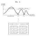
- FIG. 5 is a diagram for describing a method of deriving a set of threshold values having brightness of a shadow by heat by using characteristics of the shadow by heat according to an exemplary embodiment.
- the shadow by heat represents a higher brightness value compared to a vehicle region of a vehicle and represents a lower brightness value compared to an engine region of the vehicle.
- a result shown in the graph of FIG. 5 may be obtained.
- the shadow brightness obtaining unit 332 obtains threshold values TH L and TH H , for assorting brightness of a moving object region, a shadow region, and an engine region, according to temperatures. In other words, if extracted brightness is less than the threshold value TH L , it is determined to be the moving object region, if extracted brightness is greater than TH L and less than TH H , it is determined to be the shadow region, and if extracted brightness is greater than TH H , it is determined to be the engine region.
- the shadow brightness obtaining unit 332 calculates a threshold value to designate the best boundary region for assorting distribution with respect to the three regions by using a bayesian rule. Also, the shadow brightness obtaining unit 332 may set the threshold values having a minimum error.
- the shadow brightness obtaining unit 332 obtains the threshold values TH L and TH H according to a mean temperature. As described above, in a thermal image, characteristics of a shadow by heat vary according to temperatures, and thus the shadow brightness obtaining unit 332 obtains a set of threshold values according to temperatures.
- a lower diagram of FIG. 5 shows a set of threshold values with respect to temperatures of 0° C., 4° C., 8° C., 13° C., 18° C., and 27° C. which are obtained by the shadow brightness obtaining unit 332 .
- the learning unit 330 may obtain size and brightness information only when more than half the moving object is exposed in the thermal image.
- the detecting unit 340 obtains temperature information regarding an image to be detected, and designates a shadow region of a target object based on the size and brightness information regarding the shadow by heat of the reference object which corresponds to the corresponding temperature. As shown in FIG. 3 , the detecting unit 340 includes a candidate region designating unit 341 , a shadow region designating unit 342 , and a shadow removing unit 343 .
- the candidate region designating unit 341 measures a size of the bounding box surrounding the target object in a thermal image to be detected, and extracts a size of the shadow by heat of the target object which corresponds to the size of the corresponding bounding box by using the size parameter and function derived by the shadow size obtaining unit 331 .
- the candidate region designating unit 341 obtains temperature information regarding the thermal image to be detected.
- the candidate region designating unit 341 measures the size of the bounding box surrounding the target object detected in the thermal image.
- the candidate region detecting unit 340 extracts a size parameter and function of a corresponding temperature in the graph shown in FIG. 4 .
- the candidate region detecting unit 340 may extract a size of a shadow by heat of the target object which corresponds to the corresponding bounding box by using the extracted size parameter and function.
- the candidate region designating unit 341 may obtain a size of a corresponding shadow by heat of the target object by using a corresponding size parameter and function. If the size of the shadow by heat is obtained, the candidate region designating unit 341 designates a region corresponding to a corresponding size from the bottom of the bounding box as a shadow candidate region of the target object.
- the shadow region designating unit 342 designates a region within a range of a threshold value as a shadow region of the target object based on brightness value information about the shadow candidate region. In other words, the shadow region designating unit 342 selects a threshold value of brightness of a shadow by heat which corresponds to a temperature of a thermal image to be detected, and designates a region within the selected threshold value as a shadow region of the target object.
- the shadow region designating unit 342 selects (TH L , TH H ) 0° C . in a set of threshold values of FIG. 5 by using a corresponding threshold value.
- the shadow region designating unit 342 designates a region having brightness ranging from TH L and TH H in the shadow candidate region.
- the shadow removing unit 343 removes the designated shadow region from the bounding box. Only a purely moving object remains in the bounding box from which the shadow region is removed or disregarded.
- FIG. 6 is a flowchart for describing operations of a motion detecting system according to an exemplary embodiment.
- an infrared image is obtained from a monitoring camera (S 11 ).
- a shadow region is designated based on the size and brightness information about the shadow by heat which corresponds to a corresponding temperature by obtaining temperature information regarding an image to be detected (S 14 ).
- a shadow region designated in a region to be detected is removed or disregarded from a motion region (S 15 ).
- FIG. 7 is a flowchart for describing operations of a motion detecting system according to another exemplary embodiment.
- a size function of a shadow by heat with respect to a bounding box surrounding each of moving objects is estimated based on the characteristics of the shadow by heat categorized according to the mean temperature (S 22 ).
- threshold values for assorting a moving object region, a shadow region, and an engine region of a moving object are set based on brightness value information with respect to the above-described regions (S 23 ).
- a size of the bounding box surrounding the moving object in a region to be detected is measured, and a size of the shadow by heat which corresponds to a size of the corresponding bounding box from the size function of the shadow by heat is extracted (S 24 ).
- regions existing within the size of the shadow by heat from the bottom of the detected bounding box are designated as a shadow candidate region (S 25 ).
- a region within a range of the threshold value is designated as a shadow region based on the brightness value information about the shadow candidate region (S 26 ).
- FIG. 8 is a flowchart for describing a method of removing a shadow region by the detecting unit 340 according to another exemplary embodiment.
- the database 320 and the learning unit 330 are components that may be previously set on an off-line basis by a manager.
- the detecting unit 340 is a component that has to be individually used on an on-line basis for a thermal image to be detected.
- Data of the database 320 and the learning unit 330 may be treated as predetermined components. Accordingly, the embodiment shown in FIG. 8 shows a process of removing a shadow region from the viewpoint of the detecting unit 340 .
- an infrared image is obtained from a monitoring camera (S 31 ).
- a size of the shadow by heat is obtained from an image to be detected with reference to the characteristics of the shadow by heat (S 33 ).
- a region satisfying the size and the brightness of the shadow by heat is designated as a shadow region (S 35 ).
- accuracy of detection of a moving object may be increased by removing a shadow by heat generated due to the moving object whose heat is transferred to a background of a thermal image.
- a size and brightness of a shadow by heat according to temperatures may be obtained by analyzing characteristics of a shadow by heat and senses a shadow region based on the obtained information.
Landscapes
- Engineering & Computer Science (AREA)
- Physics & Mathematics (AREA)
- General Physics & Mathematics (AREA)
- Theoretical Computer Science (AREA)
- Multimedia (AREA)
- Computer Vision & Pattern Recognition (AREA)
- Human Computer Interaction (AREA)
- Probability & Statistics with Applications (AREA)
- General Health & Medical Sciences (AREA)
- Health & Medical Sciences (AREA)
- Social Psychology (AREA)
- Oral & Maxillofacial Surgery (AREA)
- Life Sciences & Earth Sciences (AREA)
- Bioinformatics & Cheminformatics (AREA)
- Bioinformatics & Computational Biology (AREA)
- Evolutionary Biology (AREA)
- Psychiatry (AREA)
- Software Systems (AREA)
- Signal Processing (AREA)
- Image Analysis (AREA)
Abstract
Description
Claims (18)
Applications Claiming Priority (2)
| Application Number | Priority Date | Filing Date | Title |
|---|---|---|---|
| KR1020120068176A KR101735565B1 (en) | 2012-06-25 | 2012-06-25 | Method and system for motion detection using elimination of shadow by heat |
| KR10-2012-0068176 | 2012-06-25 |
Publications (2)
| Publication Number | Publication Date |
|---|---|
| US20130343603A1 US20130343603A1 (en) | 2013-12-26 |
| US9189863B2 true US9189863B2 (en) | 2015-11-17 |
Family
ID=49774497
Family Applications (1)
| Application Number | Title | Priority Date | Filing Date |
|---|---|---|---|
| US13/887,480 Active 2033-11-14 US9189863B2 (en) | 2012-06-25 | 2013-05-06 | Method and system for detecting motion capable of removing shadow by heat |
Country Status (2)
| Country | Link |
|---|---|
| US (1) | US9189863B2 (en) |
| KR (1) | KR101735565B1 (en) |
Families Citing this family (5)
| Publication number | Priority date | Publication date | Assignee | Title |
|---|---|---|---|---|
| WO2015122161A1 (en) | 2014-02-14 | 2015-08-20 | 日本電気株式会社 | Video analysis system |
| US10373343B1 (en) * | 2015-05-28 | 2019-08-06 | Certainteed Corporation | System for visualization of a building material |
| WO2018059985A1 (en) * | 2016-09-29 | 2018-04-05 | Philips Lighting Holding B.V. | Depth queue by thermal sensing |
| TWI662289B (en) * | 2018-07-02 | 2019-06-11 | 廣達電腦股份有限公司 | Tracking distance measuring system and method thereof |
| US11195324B1 (en) | 2018-08-14 | 2021-12-07 | Certainteed Llc | Systems and methods for visualization of building structures |
Citations (10)
| Publication number | Priority date | Publication date | Assignee | Title |
|---|---|---|---|---|
| KR20030067212A (en) | 2002-02-07 | 2003-08-14 | 삼성탈레스 주식회사 | Surveillance and security methode using thermal image system |
| US20080056568A1 (en) * | 2006-08-30 | 2008-03-06 | Porikli Fatih M | Object segmentation using visible and infrared images |
| KR20090061405A (en) | 2007-12-11 | 2009-06-16 | 주식회사 메타켐 | Automatic tracking device and method using non-contact multiple infrared temperature sensor |
| US20090316957A1 (en) * | 2008-06-23 | 2009-12-24 | Chao-Ho Chen | Method of vehicle segmentation and counting for nighttime video frames |
| JP2009301494A (en) | 2008-06-17 | 2009-12-24 | Sumitomo Electric Ind Ltd | Image processing unit and image processing method |
| KR20100012992A (en) | 2008-07-30 | 2010-02-09 | 국방과학연구소 | Infrared thermal imaging device and method for processing signal using the same |
| US20100182433A1 (en) * | 2007-10-17 | 2010-07-22 | Hitachi Kokusai Electric, Inc. | Object detection system |
| KR20110035335A (en) | 2009-09-30 | 2011-04-06 | 주식회사 케이티 | Monitoring method and system using thermal imaging camera |
| KR101066900B1 (en) | 2009-04-23 | 2011-09-27 | 유한대학산학협력단 | Citigroup detects specific motion in camera images |
| KR20110114096A (en) | 2010-04-12 | 2011-10-19 | 주식회사 영국전자 | Surveillance system employing thermal camera and night surveillance method |
-
2012
- 2012-06-25 KR KR1020120068176A patent/KR101735565B1/en active Active
-
2013
- 2013-05-06 US US13/887,480 patent/US9189863B2/en active Active
Patent Citations (10)
| Publication number | Priority date | Publication date | Assignee | Title |
|---|---|---|---|---|
| KR20030067212A (en) | 2002-02-07 | 2003-08-14 | 삼성탈레스 주식회사 | Surveillance and security methode using thermal image system |
| US20080056568A1 (en) * | 2006-08-30 | 2008-03-06 | Porikli Fatih M | Object segmentation using visible and infrared images |
| US20100182433A1 (en) * | 2007-10-17 | 2010-07-22 | Hitachi Kokusai Electric, Inc. | Object detection system |
| KR20090061405A (en) | 2007-12-11 | 2009-06-16 | 주식회사 메타켐 | Automatic tracking device and method using non-contact multiple infrared temperature sensor |
| JP2009301494A (en) | 2008-06-17 | 2009-12-24 | Sumitomo Electric Ind Ltd | Image processing unit and image processing method |
| US20090316957A1 (en) * | 2008-06-23 | 2009-12-24 | Chao-Ho Chen | Method of vehicle segmentation and counting for nighttime video frames |
| KR20100012992A (en) | 2008-07-30 | 2010-02-09 | 국방과학연구소 | Infrared thermal imaging device and method for processing signal using the same |
| KR101066900B1 (en) | 2009-04-23 | 2011-09-27 | 유한대학산학협력단 | Citigroup detects specific motion in camera images |
| KR20110035335A (en) | 2009-09-30 | 2011-04-06 | 주식회사 케이티 | Monitoring method and system using thermal imaging camera |
| KR20110114096A (en) | 2010-04-12 | 2011-10-19 | 주식회사 영국전자 | Surveillance system employing thermal camera and night surveillance method |
Non-Patent Citations (6)
| Title |
|---|
| Davis et al., "Background-Subtraction in Thermal Imagery Using Contour Saliency", 2007, Springer, International Journal of Computer Vision 71(2), 161-181. * |
| Davis et al., "Robust Detection of People in Thermal Imagery", 2004, In Proceedings of the Pattern Recognition, 17th International Conference on (ICPR'04) vol. 4-vol. 04 (ICPR '04), vol. 4. IEEE Computer Society, Washington, DC, USA, 713-716. * |
| Finlayson, "On the removal of shadows from images," Jan. 2006, IEEE Pattern Analysis and Machine Intelligence, vol. 28, No. 1, pp. 59,68, Jan. 2006. * |
| Goube et al., "Pedestrian Tracking Using Thermal Infrared Imaging,", 2006, Proc. SPIE Conf. Infrared Technology and Applications, pp. 797-808. * |
| Guo et al,"Single-image shadow detection and removal using paired regions", 2011, In CVPR, 2033-2040. * |
| Li et al., "Feature Enhancement Using Gradient Salience on Thermal Image," Dec. 1-3, 2010, Digital Image Computing: Techniques and Applications (DICTA), 2010, pp. 556-562. * |
Also Published As
| Publication number | Publication date |
|---|---|
| KR101735565B1 (en) | 2017-05-15 |
| US20130343603A1 (en) | 2013-12-26 |
| KR20140000821A (en) | 2014-01-06 |
Similar Documents
| Publication | Publication Date | Title |
|---|---|---|
| US11682131B2 (en) | Image capturing apparatus and method of controlling image capturing apparatus | |
| US8798369B2 (en) | Apparatus and method for estimating the number of objects included in an image | |
| US9489747B2 (en) | Image processing apparatus for performing object recognition focusing on object motion, and image processing method therefor | |
| JP6800628B2 (en) | Tracking device, tracking method, and program | |
| US9189863B2 (en) | Method and system for detecting motion capable of removing shadow by heat | |
| CN103905727A (en) | Object area tracking apparatus, control method, and program of the same | |
| CN103261939A (en) | Image capture device and primary photographic subject recognition method | |
| JP6924064B2 (en) | Image processing device and its control method, and image pickup device | |
| CN105491285A (en) | Method and device for switching working mode of PIR camera | |
| TW201725875A (en) | Bit rate controller and method for limiting output bit rate | |
| US11575826B2 (en) | Image processing apparatus and method, and image capturing apparatus | |
| US20120033854A1 (en) | Image processing apparatus | |
| JP2007178543A (en) | Imaging apparatus | |
| JP2013098746A (en) | Imaging apparatus, imaging method, and program | |
| JP5045538B2 (en) | Imaging apparatus and program | |
| KR100781170B1 (en) | Imager | |
| JP6099973B2 (en) | Subject area tracking device, control method thereof, and program | |
| WO2022156763A1 (en) | Target object detection method and device thereof | |
| JP4871664B2 (en) | IMAGING DEVICE AND IMAGING DEVICE CONTROL METHOD | |
| US20250159329A1 (en) | Information processing apparatus | |
| JP5928024B2 (en) | Image processing apparatus, image processing method, and program | |
| WO2025150483A1 (en) | Information processing apparatus, information processing method, program, and recording medium | |
| JP6064330B2 (en) | Imaging device | |
| JP2016126046A (en) | Focal point detecting device and focal point detecting method | |
| JP2009194422A (en) | Imaging apparatus |
Legal Events
| Date | Code | Title | Description |
|---|---|---|---|
| AS | Assignment |
Owner name: SAMSUNG TECHWIN CO., LTD., KOREA, REPUBLIC OF Free format text: ASSIGNMENT OF ASSIGNORS INTEREST;ASSIGNORS:CHOI, EUN-JI;NOH, SEUNG-IN;KIM, JI-MAN;AND OTHERS;SIGNING DATES FROM 20130423 TO 20130425;REEL/FRAME:030353/0337 Owner name: POSTECH ACADEMY-INDUSTRY FOUNDATION, KOREA, REPUBL Free format text: ASSIGNMENT OF ASSIGNORS INTEREST;ASSIGNORS:CHOI, EUN-JI;NOH, SEUNG-IN;KIM, JI-MAN;AND OTHERS;SIGNING DATES FROM 20130423 TO 20130425;REEL/FRAME:030353/0337 |
|
| AS | Assignment |
Owner name: HANWHA TECHWIN CO., LTD., KOREA, REPUBLIC OF Free format text: CHANGE OF NAME;ASSIGNOR:SAMSUNG TECHWIN CO., LTD.;REEL/FRAME:036254/0911 Effective date: 20150701 |
|
| STCF | Information on status: patent grant |
Free format text: PATENTED CASE |
|
| FEPP | Fee payment procedure |
Free format text: PAYOR NUMBER ASSIGNED (ORIGINAL EVENT CODE: ASPN); ENTITY STATUS OF PATENT OWNER: LARGE ENTITY |
|
| AS | Assignment |
Owner name: HANWHA AEROSPACE CO., LTD., KOREA, REPUBLIC OF Free format text: CHANGE OF NAME;ASSIGNOR:HANWHA TECHWIN CO., LTD;REEL/FRAME:046927/0019 Effective date: 20180401 |
|
| AS | Assignment |
Owner name: HANWHA AEROSPACE CO., LTD., KOREA, REPUBLIC OF Free format text: CORRECTIVE ASSIGNMENT TO CORRECT THE APPLICATION NUMBER 10/853,669. IN ADDITION PLEASE SEE EXHIBIT A PREVIOUSLY RECORDED ON REEL 046927 FRAME 0019. ASSIGNOR(S) HEREBY CONFIRMS THE CHANGE OF NAME;ASSIGNOR:HANWHA TECHWIN CO., LTD.;REEL/FRAME:048496/0596 Effective date: 20180401 |
|
| MAFP | Maintenance fee payment |
Free format text: PAYMENT OF MAINTENANCE FEE, 4TH YEAR, LARGE ENTITY (ORIGINAL EVENT CODE: M1551); ENTITY STATUS OF PATENT OWNER: LARGE ENTITY Year of fee payment: 4 |
|
| AS | Assignment |
Owner name: HANWHA TECHWIN CO., LTD., KOREA, REPUBLIC OF Free format text: ASSIGNMENT OF ASSIGNORS INTEREST;ASSIGNOR:HANWHA AEROSPACE CO., LTD.;REEL/FRAME:049013/0723 Effective date: 20190417 |
|
| MAFP | Maintenance fee payment |
Free format text: PAYMENT OF MAINTENANCE FEE, 8TH YEAR, LARGE ENTITY (ORIGINAL EVENT CODE: M1552); ENTITY STATUS OF PATENT OWNER: LARGE ENTITY Year of fee payment: 8 |
|
| AS | Assignment |
Owner name: HANWHA VISION CO., LTD., KOREA, REPUBLIC OF Free format text: CHANGE OF NAME;ASSIGNOR:HANWHA TECHWIN CO., LTD.;REEL/FRAME:064549/0075 Effective date: 20230228 |