US9188520B1 - Tensile testing apparatus - Google Patents
Tensile testing apparatus Download PDFInfo
- Publication number
- US9188520B1 US9188520B1 US14/086,824 US201314086824A US9188520B1 US 9188520 B1 US9188520 B1 US 9188520B1 US 201314086824 A US201314086824 A US 201314086824A US 9188520 B1 US9188520 B1 US 9188520B1
- Authority
- US
- United States
- Prior art keywords
- force
- support system
- set forth
- imposing
- platen
- Prior art date
- Legal status (The legal status is an assumption and is not a legal conclusion. Google has not performed a legal analysis and makes no representation as to the accuracy of the status listed.)
- Expired - Fee Related, expires
Links
- 238000009864 tensile test Methods 0.000 title claims abstract description 11
- 238000009434 installation Methods 0.000 claims abstract description 14
- 238000006073 displacement reaction Methods 0.000 claims abstract description 11
- 239000012530 fluid Substances 0.000 claims description 8
- 230000008878 coupling Effects 0.000 claims 2
- 238000010168 coupling process Methods 0.000 claims 2
- 238000005859 coupling reaction Methods 0.000 claims 2
- 238000000034 method Methods 0.000 claims 2
- 230000003213 activating effect Effects 0.000 claims 1
- 238000013480 data collection Methods 0.000 claims 1
- 239000011435 rock Substances 0.000 description 15
- 210000002435 tendon Anatomy 0.000 description 3
- 230000000007 visual effect Effects 0.000 description 2
- 238000000418 atomic force spectrum Methods 0.000 description 1
Images


Classifications
-
- G—PHYSICS
- G01—MEASURING; TESTING
- G01N—INVESTIGATING OR ANALYSING MATERIALS BY DETERMINING THEIR CHEMICAL OR PHYSICAL PROPERTIES
- G01N3/00—Investigating strength properties of solid materials by application of mechanical stress
- G01N3/08—Investigating strength properties of solid materials by application of mechanical stress by applying steady tensile or compressive forces
- G01N3/10—Investigating strength properties of solid materials by application of mechanical stress by applying steady tensile or compressive forces generated by pneumatic or hydraulic pressure
-
- G—PHYSICS
- G01—MEASURING; TESTING
- G01N—INVESTIGATING OR ANALYSING MATERIALS BY DETERMINING THEIR CHEMICAL OR PHYSICAL PROPERTIES
- G01N3/00—Investigating strength properties of solid materials by application of mechanical stress
- G01N3/02—Details
- G01N3/06—Special adaptations of indicating or recording means
- G01N3/068—Special adaptations of indicating or recording means with optical indicating or recording means
-
- H—ELECTRICITY
- H04—ELECTRIC COMMUNICATION TECHNIQUE
- H04N—PICTORIAL COMMUNICATION, e.g. TELEVISION
- H04N5/00—Details of television systems
- H04N5/76—Television signal recording
-
- G—PHYSICS
- G01—MEASURING; TESTING
- G01N—INVESTIGATING OR ANALYSING MATERIALS BY DETERMINING THEIR CHEMICAL OR PHYSICAL PROPERTIES
- G01N2203/00—Investigating strength properties of solid materials by application of mechanical stress
- G01N2203/02—Details not specific for a particular testing method
- G01N2203/06—Indicating or recording means; Sensing means
- G01N2203/0641—Indicating or recording means; Sensing means using optical, X-ray, ultraviolet, infrared or similar detectors
- G01N2203/0647—Image analysis
Definitions
- a tendon type support system such as a mechanical rock bolt system, can be used to stabilize rock in a tunnel or mine.
- a bolt system supports the rock that makes up the immediate roof structure by supporting it from a stronger or more stable rock structure that lies above.
- An apparatus for tensile testing of a tendon-type support system that simultaneously tests the total system, subsystems, and individual components. Additionally or alternatively, the testing apparatus allows the system's tendon element to be anchored to a platen part in the same way as it is anchored in a field installation.
- FIG. 1 shows an apparatus for tensile testing of a tendon-type support system.
- FIG. 2 shows output features of the apparatus.
- FIG. 3 shows tendon-type support systems in an installation condition.
- FIGS. 4-5 show a tendon-type support system before and after forces are imposed.
- FIG. 6 shows the tendon-type support system mounted in the apparatus for testing.
- FIG. 7 shows the tendon-type support system being tested by the apparatus.
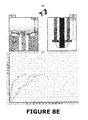
- FIGS. 8A-8H show some comprehensive output formats that can be provided by the apparatus.
- the apparatus 10 can be made more compact, light weight and portable than commercially available equipment whereby it can be easily broken down, transported by hand, and quickly reassembled to conduct tests at different locations as needed.
- the apparatus 10 can be constructed, for example, with a footprint of less than 10 square feet (e.g., about 3 feet by 3 feet) and/or with a weight less than 1000 pounds (e.g., around 500 pounds). Additionally or alternatively, the apparatus 10 can be adapted to test much longer specimens than conventional equipment and thus is useful in analyzing long specimens in their entirety.
- the testing apparatus 10 comprises a force-imposing device 20 designed to impose force on the tendon-type support system in a manner duplicating that which it will encounter in its installation setting.
- the illustrated device 20 comprises a cylinder 21 having a central bore 22 and an annular fluid chamber 23 therearound.
- a ram 24 is slidably mounted within the chamber 23 so as to move vertically in response to fluid contained therein.
- the ram 24 has a central bore 25 aligned with the central bore 22 of the cylinder 21 .
- a fluid source 26 e.g., a pump
- the cylinder-ram components of the force-imposing device 20 can be mounted on a table 30 having a horizontal platform 31 and vertical legs 32 .
- the cylinder 21 extends partially through an opening 33 in the platform 31 and is held in place by a bracket 34 .
- the tensile testing apparatus 10 additionally comprises a platen 40 adapted to pose a tendon-type support system in a way representative of its installation setting.
- the platen 40 is fixed to the top of the cylinder 21 and has a central bore 41 aligned with those of the force-imposing device 20 .
- An upper surface 42 surrounds the central bore 41 and includes a counterbore 43 .
- the tensile testing apparatus 10 further comprises an assembly 50 for fixturing the to-be-tested support system to the force-imposing device 20 .
- the fixturing assembly 50 includes a pipe 51 , a washer 52 , and locking elements 53 .
- the pipe 51 has a central bore 54 and the washer 52 has a central opening 52 which are alignable with the ram's central bore 25 .
- Sensing equipment 60 can be situated to sense changes above the platen 40 and sensing equipment 70 can be situated to sense changes below the pipe 51 (or at least below the ram 24 ).
- This equipment can include electronic position sensors 61 and 71 linked to determine vertical displacement. Cameras 62 and 72 can be placed near the sensors 61 and 71 to visually record changes and video document a test from start to finish.
- a microphone 63 can also be strategically located to record relevant sounds associated with the testing. These sounds can include, for example, the “pops”, “pings”, “kings”, “rings”, and “booms” which occur as components deform, fail, and redistribute load to other components.
- a data-collecting station 80 can collect data from the force-imposing device 20 and the sensing equipment 60 - 70 . As shown in FIG. 2 , the data collecting station 80 can convey data to an output station 90 which outputs the data in visual formats 91 - 92 , a graphical format 93 , and/or graphical format 93 .
- the output station 90 can be incorporated into a conventional laptop computer.
- the apparatus 10 can be used to tensile test a tendon-type support system, such as the mechanical rock bolt systems 100 depicted in FIG. 3 .
- the illustrated support systems 100 are shown in a mine or tunnel 110 .
- Each system 100 supports the rock that makes up the immediate roof structure 111 by supporting it from a stronger or more stable rock structure 112 that lies above.
- the tendon-type support system 100 can involve a cylindrical borehole 101 , drilled through the to-be-supported rock structure 111 and into the support-providing rock structure 112 .
- the system 100 can comprise a roof bolt 120 , an anchor 130 , a roof plate 140 , and a washer 150 .
- the rock bolt 120 constitutes the “tendon” element of the support system 100 . It can comprise a cylindrical body 121 having an upper threaded portion 122 and a lower end 123 . A circular flange 124 and a square bolt head 124 are located on the body's lower end 123 .
- the anchor 130 is situated in an upper region of the borehole 101 and includes a wedge part 131 and a leaf part 132 .
- the upper threaded portion 122 of the bolt 120 is in contact with the anchor's wedge part 131 .
- the wedge part 131 acts upon the leaf part 132 when the bolt 120 is pulled in a downward direction.
- the roof plate 140 has an upper face in contact with the roof rock structure 111 and a lower face adjacent an upper face of the washer 150 .
- FIG. 4 a tendon-type support system 100 is shown immediately after installation, prior to any force being applied.
- FIG. 5 a system 100 is shown as it might exist after a typical Force F is applied. This Force F is transferred from the supported rock structure 111 to the bearing plate 140 to the washer 150 , to the bolt flange 124 and then to the bolt head 125 . From the bolt head 125 , the Force F is transferred to the bolt body 121 to the threaded upper portion 122 , into the anchor 130 , and then into the stable rock structure 112 .
- the support system 100 To test the support system 100 , it is mounted on the test apparatus 10 as shown in FIG. 6 in a manner resembling its installation, except up-side-down in orientation. Specifically, for example, the plate 140 and the washer 150 are placed on the platen 40 . The bolt 120 is lowered through the aligned bores and through the fixturing pipe 51 . The washer 52 and the wedge elements 53 are assembled onto the bolt's end portion 122 to secure it to the pipe 51 .
- fluid can be supplied (e.g., pumped) to the cylinder 21 from the source 26 .
- This force simulates that experienced by the system 100 in its installation setting and thus it displaces in a corresponding manner.
- the sensor 61 monitors upper displacement (e.g., the combined displacement of the bolt flange 124 , the bolt head 125 , the plate 140 and the washer 150 ) and the sensor 71 monitors total displacement (e.g., the upper displacement seen by sensor 61 and displacement caused by lower bolt portions).
- the camera 62 visually records changes in the upper-displacement components
- the camera 72 visually records changes in the bolt body 121
- the microphone 63 audibly records relevant sounds. This data is conveyed to the collection station 80 and to the output station 90 , for compilation into an easily understandable format.
- test data can be output in video formats, graphical formats, and/or audio formats.
- video formats graphical formats, and/or audio formats.
- the combination of some or all of these formats may often provide the meaningful analysis. For example, visual images corresponding to plotted points correlate component deformation with force curves to fully appreciate failure sequences during testing.
Landscapes
- Chemical & Material Sciences (AREA)
- Pathology (AREA)
- Analytical Chemistry (AREA)
- Physics & Mathematics (AREA)
- Health & Medical Sciences (AREA)
- Life Sciences & Earth Sciences (AREA)
- Biochemistry (AREA)
- Immunology (AREA)
- General Physics & Mathematics (AREA)
- General Health & Medical Sciences (AREA)
- Multimedia (AREA)
- Engineering & Computer Science (AREA)
- Signal Processing (AREA)
- Investigating Strength Of Materials By Application Of Mechanical Stress (AREA)
Abstract
Description
Claims (20)
Priority Applications (1)
| Application Number | Priority Date | Filing Date | Title |
|---|---|---|---|
| US14/086,824 US9188520B1 (en) | 2013-11-21 | 2013-11-21 | Tensile testing apparatus |
Applications Claiming Priority (1)
| Application Number | Priority Date | Filing Date | Title |
|---|---|---|---|
| US14/086,824 US9188520B1 (en) | 2013-11-21 | 2013-11-21 | Tensile testing apparatus |
Publications (1)
| Publication Number | Publication Date |
|---|---|
| US9188520B1 true US9188520B1 (en) | 2015-11-17 |
Family
ID=54434550
Family Applications (1)
| Application Number | Title | Priority Date | Filing Date |
|---|---|---|---|
| US14/086,824 Expired - Fee Related US9188520B1 (en) | 2013-11-21 | 2013-11-21 | Tensile testing apparatus |
Country Status (1)
| Country | Link |
|---|---|
| US (1) | US9188520B1 (en) |
Cited By (6)
| Publication number | Priority date | Publication date | Assignee | Title |
|---|---|---|---|---|
| CN105571945A (en) * | 2015-12-18 | 2016-05-11 | 中国科学院地质与地球物理研究所 | Rock in-situ micro-tension sample and test method |
| US20190078987A1 (en) * | 2017-04-28 | 2019-03-14 | Shandong University | Intelligent numerically-controlled ultrahigh pressure true three-dimensional non-uniform loading/unloading and steady pressure model test system |
| CN110031311A (en) * | 2019-05-20 | 2019-07-19 | 贵州工程应用技术学院 | The method of rapid survey rock tensile mechanical properties |
| CN110462228A (en) * | 2017-03-27 | 2019-11-15 | 费希尔厂有限责任两合公司 | Arrangement and fixing system of anchor bolts in anchor holes |
| CN110836820A (en) * | 2019-11-28 | 2020-02-25 | 泰安泰烁岩层控制科技有限公司 | Positioning module and anchor cable drawing test device thereof |
| CN120404327A (en) * | 2025-07-01 | 2025-08-01 | 兰州石化职业技术大学 | A product defect detection device and detection method based on machine vision |
Citations (17)
| Publication number | Priority date | Publication date | Assignee | Title |
|---|---|---|---|---|
| US3721119A (en) | 1971-09-17 | 1973-03-20 | Tinius Olsen Testing Mach Co | Tensile testing machine |
| US3776030A (en) | 1972-10-05 | 1973-12-04 | Tinius Olsen Testing Mach Co | Extensometer |
| US3835699A (en) | 1973-09-27 | 1974-09-17 | Tinius Olsen Testing Mach Co | Long stroke testing machine |
| US3943819A (en) | 1974-08-22 | 1976-03-16 | Charron Charles S | Tensile member with tension indicating means |
| US4062229A (en) | 1977-02-22 | 1977-12-13 | General Electric Company | Method of testing the integrity of installed rock bolts |
| US4281547A (en) | 1979-05-10 | 1981-08-04 | Conoco, Inc. (Formerly Continental Oil Company) | Electronic mine roof bolt tester |
| US4318302A (en) | 1978-12-13 | 1982-03-09 | Conoco Inc. | Method of determining mine roof stability |
| US4601207A (en) | 1985-01-11 | 1986-07-22 | The United States Of America As Represented By The Secretary Of The Interior | Measuring mine roof bolt strains |
| US4624144A (en) | 1984-05-23 | 1986-11-25 | Tinius Olsen Testing Machine Co. | For testing machines, improvements in determining rupture point and setting gauge length |
| US4944188A (en) | 1989-05-10 | 1990-07-31 | Dial John H | Fastener tester |
| US5232311A (en) * | 1991-05-20 | 1993-08-03 | Jennmar Corporation | Roof control system |
| US5542788A (en) * | 1993-11-12 | 1996-08-06 | Jennmar Corporation | Method and apparatus for monitoring mine roof support systems |
| US5598738A (en) * | 1995-04-03 | 1997-02-04 | Lockheed Idaho Technologies Company | Load apparatus and method for bolt-loaded compact tension test specimen |
| US6041660A (en) * | 1997-07-01 | 2000-03-28 | Ricoh Company, Ltd. | Tensile strength tester |
| US6370962B1 (en) * | 2000-06-14 | 2002-04-16 | Testing Machines, Inc. | Dynamic high speed tensile tester |
| US7324007B2 (en) | 2001-12-31 | 2008-01-29 | The United States Of America As Represented By The Secretary Of The Department Of Health And Human Services, Centers For Disease Control And Prevention | Instrumented rock bolt, data logger and user interface system |
| US8224631B2 (en) * | 2008-08-18 | 2012-07-17 | Fci Holdings Delaware, Inc. | Stress, geologic, and support analysis methodology for underground openings |
-
2013
- 2013-11-21 US US14/086,824 patent/US9188520B1/en not_active Expired - Fee Related
Patent Citations (18)
| Publication number | Priority date | Publication date | Assignee | Title |
|---|---|---|---|---|
| US3721119A (en) | 1971-09-17 | 1973-03-20 | Tinius Olsen Testing Mach Co | Tensile testing machine |
| US3776030A (en) | 1972-10-05 | 1973-12-04 | Tinius Olsen Testing Mach Co | Extensometer |
| US3835699A (en) | 1973-09-27 | 1974-09-17 | Tinius Olsen Testing Mach Co | Long stroke testing machine |
| US3943819A (en) | 1974-08-22 | 1976-03-16 | Charron Charles S | Tensile member with tension indicating means |
| US4062229A (en) | 1977-02-22 | 1977-12-13 | General Electric Company | Method of testing the integrity of installed rock bolts |
| US4318302A (en) | 1978-12-13 | 1982-03-09 | Conoco Inc. | Method of determining mine roof stability |
| US4281547A (en) | 1979-05-10 | 1981-08-04 | Conoco, Inc. (Formerly Continental Oil Company) | Electronic mine roof bolt tester |
| US4624144A (en) | 1984-05-23 | 1986-11-25 | Tinius Olsen Testing Machine Co. | For testing machines, improvements in determining rupture point and setting gauge length |
| US4601207A (en) | 1985-01-11 | 1986-07-22 | The United States Of America As Represented By The Secretary Of The Interior | Measuring mine roof bolt strains |
| US4944188A (en) | 1989-05-10 | 1990-07-31 | Dial John H | Fastener tester |
| US5232311A (en) * | 1991-05-20 | 1993-08-03 | Jennmar Corporation | Roof control system |
| USRE36019E (en) | 1991-05-20 | 1998-12-29 | Jennmar Corporation | Roof control system |
| US5542788A (en) * | 1993-11-12 | 1996-08-06 | Jennmar Corporation | Method and apparatus for monitoring mine roof support systems |
| US5598738A (en) * | 1995-04-03 | 1997-02-04 | Lockheed Idaho Technologies Company | Load apparatus and method for bolt-loaded compact tension test specimen |
| US6041660A (en) * | 1997-07-01 | 2000-03-28 | Ricoh Company, Ltd. | Tensile strength tester |
| US6370962B1 (en) * | 2000-06-14 | 2002-04-16 | Testing Machines, Inc. | Dynamic high speed tensile tester |
| US7324007B2 (en) | 2001-12-31 | 2008-01-29 | The United States Of America As Represented By The Secretary Of The Department Of Health And Human Services, Centers For Disease Control And Prevention | Instrumented rock bolt, data logger and user interface system |
| US8224631B2 (en) * | 2008-08-18 | 2012-07-17 | Fci Holdings Delaware, Inc. | Stress, geologic, and support analysis methodology for underground openings |
Cited By (10)
| Publication number | Priority date | Publication date | Assignee | Title |
|---|---|---|---|---|
| CN105571945A (en) * | 2015-12-18 | 2016-05-11 | 中国科学院地质与地球物理研究所 | Rock in-situ micro-tension sample and test method |
| CN110462228A (en) * | 2017-03-27 | 2019-11-15 | 费希尔厂有限责任两合公司 | Arrangement and fixing system of anchor bolts in anchor holes |
| CN110462228B (en) * | 2017-03-27 | 2021-08-31 | 费希尔厂有限责任两合公司 | Arrangement and fixing system of anchor bolts in anchor holes |
| US20190078987A1 (en) * | 2017-04-28 | 2019-03-14 | Shandong University | Intelligent numerically-controlled ultrahigh pressure true three-dimensional non-uniform loading/unloading and steady pressure model test system |
| US10408718B2 (en) * | 2017-04-28 | 2019-09-10 | Shandong University | Three-dimensional non-uniform loading/unloading and steady pressure model test system |
| CN110031311A (en) * | 2019-05-20 | 2019-07-19 | 贵州工程应用技术学院 | The method of rapid survey rock tensile mechanical properties |
| CN110031311B (en) * | 2019-05-20 | 2021-12-17 | 贵州工程应用技术学院 | Method for rapidly measuring tensile mechanical property of rock |
| CN110836820A (en) * | 2019-11-28 | 2020-02-25 | 泰安泰烁岩层控制科技有限公司 | Positioning module and anchor cable drawing test device thereof |
| CN110836820B (en) * | 2019-11-28 | 2021-12-07 | 泰安泰烁岩层控制科技有限公司 | Positioning module and anchor cable drawing test device thereof |
| CN120404327A (en) * | 2025-07-01 | 2025-08-01 | 兰州石化职业技术大学 | A product defect detection device and detection method based on machine vision |
Similar Documents
| Publication | Publication Date | Title |
|---|---|---|
| US9188520B1 (en) | Tensile testing apparatus | |
| US20200319070A1 (en) | Rock impact loading-unloading confining pressure test system and usage method therefor | |
| US9039329B2 (en) | Pipeline insertion system | |
| RU2759554C1 (en) | System and method for borehole inspection for ultra-deep vertical borehole | |
| CN105928871B (en) | A friction test system and test method for shaped explosives | |
| CN101446545A (en) | Anchoring body rheologic drawing device and test method | |
| CN106321968A (en) | Spring support hanger with automatic monitoring, analyzing and early warning functions | |
| CN110208114B (en) | Interface vibration single shear test device and method for simulating power contact problem | |
| CN104749036B (en) | Rock mechanics system and method in situ | |
| CN112885220A (en) | Landslide and slide belt model test system and method | |
| CN105277149B (en) | Faying face real contact area measurement apparatus and measuring method | |
| CN105352635A (en) | Spatial pre-embedded type three-dimensional stress monitoring system and method for underground coal and rock mass | |
| CN106052999B (en) | Seismic test device and test method for outer surface of UHV DC composite wall bushing | |
| CN109141518A (en) | A kind of big stage afterwards filling body unstable failure test device of unilateral exposure and method | |
| CN206112258U (en) | Spring hangers and support with automatic monitoring analysis and warning function | |
| EA015030B1 (en) | An apparatus and a method for leakage testing and/or pressure testing of a portion of a pipe | |
| CN106052996B (en) | Seismic test device and test method for UHV DC composite wall bushing | |
| CN109100232A (en) | The experimental rig and application method of cone vertical bearing capacity are climbed for detecting bridge tower | |
| CN106226177B (en) | Extra-high voltage direct current composite wall bushing internal and external anti-seismic testing device and testing method | |
| CN207585937U (en) | A kind of experimental rig of the horizontal loading of tunnel lining structure | |
| Wang et al. | Field test system for investigating dynamic ice forces on jacket structures and platform safety guarantee in the Bohai Sea | |
| CN105672310A (en) | Anchor head displacement measuring device and method | |
| CN109781530A (en) | In-situ measuring device and method for compressive strength of working face bottom plate | |
| CN112012254B (en) | Comprehensive detection method of pile foundation based on unloading point method | |
| CN105067156B (en) | Tunnel stability of foundation of fan suspended online test method and system based on pressure measxurement displacement |
Legal Events
| Date | Code | Title | Description |
|---|---|---|---|
| AS | Assignment |
Owner name: ENGINEERED MINE SOLUTIONS, LLC, OHIO Free format text: ASSIGNMENT OF ASSIGNORS INTEREST;ASSIGNOR:SMITH, GREGORY EARL;REEL/FRAME:036643/0038 Effective date: 20150924 |
|
| STCF | Information on status: patent grant |
Free format text: PATENTED CASE |
|
| FEPP | Fee payment procedure |
Free format text: MAINTENANCE FEE REMINDER MAILED (ORIGINAL EVENT CODE: REM.); ENTITY STATUS OF PATENT OWNER: MICROENTITY |
|
| LAPS | Lapse for failure to pay maintenance fees |
Free format text: PATENT EXPIRED FOR FAILURE TO PAY MAINTENANCE FEES (ORIGINAL EVENT CODE: EXP.); ENTITY STATUS OF PATENT OWNER: MICROENTITY |
|
| STCH | Information on status: patent discontinuation |
Free format text: PATENT EXPIRED DUE TO NONPAYMENT OF MAINTENANCE FEES UNDER 37 CFR 1.362 |
|
| FP | Lapsed due to failure to pay maintenance fee |
Effective date: 20191117 |