US9185194B2 - Handheld electronic device, support assembly, and support assembly fabricating method - Google Patents

Handheld electronic device, support assembly, and support assembly fabricating method Download PDF

Info

Publication number
US9185194B2
US9185194B2 US14/465,426 US201414465426A US9185194B2 US 9185194 B2 US9185194 B2 US 9185194B2 US 201414465426 A US201414465426 A US 201414465426A US 9185194 B2 US9185194 B2 US 9185194B2
Authority
US
United States
Prior art keywords
internal structure
support assembly
electronic device
structure support
handheld electronic
Prior art date
Legal status (The legal status is an assumption and is not a legal conclusion. Google has not performed a legal analysis and makes no representation as to the accuracy of the status listed.)
Active
Application number
US14/465,426
Other versions
US20150011271A1 (en
Inventor
Ailan Zhu
Mingxing YANG
Current Assignee (The listed assignees may be inaccurate. Google has not performed a legal analysis and makes no representation or warranty as to the accuracy of the list.)
Huawei Technologies Co Ltd
Original Assignee
Huawei Technologies Co Ltd
Priority date (The priority date is an assumption and is not a legal conclusion. Google has not performed a legal analysis and makes no representation as to the accuracy of the date listed.)
Filing date
Publication date
Application filed by Huawei Technologies Co Ltd filed Critical Huawei Technologies Co Ltd
Assigned to HUAWEI TECHNOLOGIES CO., LTD. reassignment HUAWEI TECHNOLOGIES CO., LTD. ASSIGNMENT OF ASSIGNORS INTEREST (SEE DOCUMENT FOR DETAILS). Assignors: YANG, Mingxing, ZHU, Ailan
Publication of US20150011271A1 publication Critical patent/US20150011271A1/en
Priority to US14/878,812 priority Critical patent/US9426263B2/en
Application granted granted Critical
Publication of US9185194B2 publication Critical patent/US9185194B2/en
Active legal-status Critical Current
Anticipated expiration legal-status Critical

Links

Images

Classifications

    • HELECTRICITY
    • H04ELECTRIC COMMUNICATION TECHNIQUE
    • H04MTELEPHONIC COMMUNICATION
    • H04M1/00Substation equipment, e.g. for use by subscribers
    • H04M1/02Constructional features of telephone sets
    • H04M1/0202Portable telephone sets, e.g. cordless phones, mobile phones or bar type handsets
    • BPERFORMING OPERATIONS; TRANSPORTING
    • B22CASTING; POWDER METALLURGY
    • B22DCASTING OF METALS; CASTING OF OTHER SUBSTANCES BY THE SAME PROCESSES OR DEVICES
    • B22D17/00Pressure die casting or injection die casting, i.e. casting in which the metal is forced into a mould under high pressure
    • B22D17/007Semi-solid pressure die casting
    • BPERFORMING OPERATIONS; TRANSPORTING
    • B22CASTING; POWDER METALLURGY
    • B22DCASTING OF METALS; CASTING OF OTHER SUBSTANCES BY THE SAME PROCESSES OR DEVICES
    • B22D17/00Pressure die casting or injection die casting, i.e. casting in which the metal is forced into a mould under high pressure
    • B22D17/14Machines with evacuated die cavity
    • BPERFORMING OPERATIONS; TRANSPORTING
    • B22CASTING; POWDER METALLURGY
    • B22DCASTING OF METALS; CASTING OF OTHER SUBSTANCES BY THE SAME PROCESSES OR DEVICES
    • B22D17/00Pressure die casting or injection die casting, i.e. casting in which the metal is forced into a mould under high pressure
    • B22D17/20Accessories: Details
    • B22D17/2015Means for forcing the molten metal into the die
    • BPERFORMING OPERATIONS; TRANSPORTING
    • B22CASTING; POWDER METALLURGY
    • B22DCASTING OF METALS; CASTING OF OTHER SUBSTANCES BY THE SAME PROCESSES OR DEVICES
    • B22D21/00Casting non-ferrous metals or metallic compounds so far as their metallurgical properties are of importance for the casting procedure; Selection of compositions therefor
    • B22D21/02Casting exceedingly oxidisable non-ferrous metals, e.g. in inert atmosphere
    • B22D21/022Casting heavy metals, with exceedingly high melting points, i.e. more than 1600 degrees C, e.g. W 3380 degrees C, Ta 3000 degrees C, Mo 2620 degrees C, Zr 1860 degrees C, Cr 1765 degrees C, V 1715 degrees C
    • BPERFORMING OPERATIONS; TRANSPORTING
    • B22CASTING; POWDER METALLURGY
    • B22DCASTING OF METALS; CASTING OF OTHER SUBSTANCES BY THE SAME PROCESSES OR DEVICES
    • B22D25/00Special casting characterised by the nature of the product
    • B22D25/06Special casting characterised by the nature of the product by its physical properties
    • BPERFORMING OPERATIONS; TRANSPORTING
    • B22CASTING; POWDER METALLURGY
    • B22DCASTING OF METALS; CASTING OF OTHER SUBSTANCES BY THE SAME PROCESSES OR DEVICES
    • B22D27/00Treating the metal in the mould while it is molten or ductile ; Pressure or vacuum casting
    • B22D27/04Influencing the temperature of the metal, e.g. by heating or cooling the mould
    • CCHEMISTRY; METALLURGY
    • C22METALLURGY; FERROUS OR NON-FERROUS ALLOYS; TREATMENT OF ALLOYS OR NON-FERROUS METALS
    • C22CALLOYS
    • C22C1/00Making non-ferrous alloys
    • C22C1/11Making amorphous alloys
    • CCHEMISTRY; METALLURGY
    • C22METALLURGY; FERROUS OR NON-FERROUS ALLOYS; TREATMENT OF ALLOYS OR NON-FERROUS METALS
    • C22CALLOYS
    • C22C45/00Amorphous alloys
    • CCHEMISTRY; METALLURGY
    • C22METALLURGY; FERROUS OR NON-FERROUS ALLOYS; TREATMENT OF ALLOYS OR NON-FERROUS METALS
    • C22CALLOYS
    • C22C45/00Amorphous alloys
    • C22C45/10Amorphous alloys with molybdenum, tungsten, niobium, tantalum, titanium, or zirconium or Hf as the major constituent
    • CCHEMISTRY; METALLURGY
    • C22METALLURGY; FERROUS OR NON-FERROUS ALLOYS; TREATMENT OF ALLOYS OR NON-FERROUS METALS
    • C22CALLOYS
    • C22C47/00Making alloys containing metallic or non-metallic fibres or filaments
    • HELECTRICITY
    • H04ELECTRIC COMMUNICATION TECHNIQUE
    • H04MTELEPHONIC COMMUNICATION
    • H04M1/00Substation equipment, e.g. for use by subscribers
    • H04M1/02Constructional features of telephone sets
    • H04M1/0202Portable telephone sets, e.g. cordless phones, mobile phones or bar type handsets
    • H04M1/026Details of the structure or mounting of specific components
    • H04M1/0266Details of the structure or mounting of specific components for a display module assembly
    • HELECTRICITY
    • H05ELECTRIC TECHNIQUES NOT OTHERWISE PROVIDED FOR
    • H05KPRINTED CIRCUITS; CASINGS OR CONSTRUCTIONAL DETAILS OF ELECTRIC APPARATUS; MANUFACTURE OF ASSEMBLAGES OF ELECTRICAL COMPONENTS
    • H05K5/00Casings, cabinets or drawers for electric apparatus
    • H05K5/0004Casings, cabinets or drawers for electric apparatus comprising several parts forming a closed casing

Definitions

  • the present invention relates to the field of electronic technologies, and in particular, to a handheld electronic device, a support assembly, and a support assembly fabricating method.
  • a handheld electronic device for example, a mobile phone
  • a touch screen assembly for example, a rear cover
  • an internal structure support assembly for example, an appearance part
  • an appearance part and so on.
  • Traditional appearance parts and internal structure support assemblies usually are made of high-strength and high-hardness materials like stainless steel or aluminum alloy. Due to the high-strength and high-hardness materials of the appearance part, the appearance part and the internal structure support assembly can be connected only in a screw locking manner or a welding manner. As a result, a mobile phone assembling process is relatively complicated with a high cost.
  • the technical issue to be solved by embodiments of the present invention is to provide a handheld electronic device, a support assembly, and a support assembly fabricating method, so as to simplify a mobile phone assembling process.
  • the present invention provides a support assembly mounted between a rear cover and a screen of a handheld electronic device to support and fasten a component of the handheld electronic device, where the support assembly includes an appearance part and an internal structure support part, where the appearance part and the internal structure support part are fabricated through integral molding of an amorphous alloy; the internal structure support part is formed by extending the top or the middle of the appearance part inwards; and an average thickness of the internal structure support part is less than 2 mm.
  • the present invention further provides a support assembly fabricating method, including:
  • the support assembly includes an appearance part and an internal structure support part that undergoes one-time near net shape forming with the appearance part.
  • the present invention further provides a handheld electronic device, including a rear cover, a component, and a support assembly, where the support assembly is mounted between the rear cover and the screen to support and fasten the component; the support assembly includes an appearance part and an internal structure support part, where the appearance part and the internal structure support part are fabricated through integral molding of an amorphous alloy; the internal structure support part is formed by extending the top or the middle of the appearance part inwards; and an average thickness of the internal structure support part is less than 2 mm.
  • the appearance part and the internal structure support part are fabricated through integral molding of an amorphous alloy.
  • the internal structure support part is formed by extending the top or the middle of the appearance part inwards, and the average thickness of the internal structure support part is less than 2 mm.
  • the appearance part 41 and the internal structure support assembly of the present invention do not need to be connected in a screw locking manner or welding manner, thereby simplifying a process of assembling the handheld electronic device 100 .
  • FIG. 1 is a schematic decomposition diagram of a mobile electronic device according to a preferred implementation manner of the present invention
  • FIG. 2 is a schematic diagram of a support assembly in FIG. 1 ;
  • FIG. 3 is a flowchart of a support assembly according to a first preferred implementation manner of the present invention.
  • FIG. 4 is a flowchart of a support assembly according to a second preferred implementation manner of the present invention.
  • FIG. 1 shows a handheld electronic device 100 according to a preferred embodiment of the present invention.
  • the handheld electronic device 100 includes a rear cover 10 , a screen 20 , a component (not shown), and a support assembly 40 .
  • the support assembly 40 is mounted between the rear cover 10 and the screen 20 to support and fasten the component.
  • the support assembly 40 includes an appearance part 41 and an internal structure support part 42 .
  • the appearance part 41 and the internal structure support part 42 are fabricated through integral molding of an amorphous alloy.
  • the internal structure support part 42 is formed by extending the top or the middle of the appearance part 41 inwards.
  • An average thickness of the internal structure support part 42 is less than 2 mm.
  • a height H of the appearance part 41 ranges from 0.5 mm to 10 mm.
  • a wall thickness W 1 of the appearance part 41 ranges from 0.5 mm to 3 mm.
  • a thickness W 2 of a support area of the internal structure support part 42 ranges from 0.2 mm to 2 mm.
  • the appearance part 41 and the internal structure support part 42 undergo one-time near net shape forming by using a zirconium-based amorphous alloy die-casting or semi-solid forming process.
  • a through-slot 422 is disposed on the internal structure support part 42 and is configured to contain the component disposed on the internal structure support part 42 .
  • An external surface of the appearance part 41 shows a metal texture after undergoing highlight polishing or sand blasting and brushing processing.
  • the amorphous alloy is a zirconium-based amorphous alloy.
  • the amorphous alloy may be adjusted according to an actual need, but the adjusted material must also be an amorphous alloy. This is because, only by using an amorphous alloy, can a support assembly with an internal component less than 2 mm be molded in an integral molding manner to meet requirements of an ultra thin handheld electronic device and a high-strength support assembly.
  • the appearance part 41 and the internal structure support part 42 are fabricated through integral molding of an amorphous alloy.
  • the internal structure support part is formed by extending the top or the middle of the appearance part inwards, and the average thickness of the internal structure support part is less than 2 mm.
  • the appearance part 41 and the internal structure support assembly of the present invention do not need to be connected in a screw locking manner or welding manner, thereby simplifying a process of assembling the handheld electronic device 100 .
  • FIG. 2 is a flowchart of a support assembly fabricating method according to a first preferred implementation manner of the present invention, the method may include the following steps:
  • Step 101 Providing a vacuum die-casting mold.
  • the vacuum die-casting mold is designed according to the specific dimension of the support assembly. Therefore, the vacuum die-casting mold may be designed according to a user requirement, and the molded support assembly that has undergone die-casting by the vacuum die-casting mold fully complies with the designed dimension of the user.
  • Step 102 Heating and melting an amorphous alloy under a vacuum environment to cause a material temperature of the amorphous alloy to be higher than a preset temperature range of the melting point of the amorphous alloy.
  • a vacuum degree of the vacuum environment is greater than 500 Pascals.
  • the preset temperature range is 50 degrees Celsius to 300 degrees Celsius.
  • the amorphous alloy is a zirconium-based amorphous alloy.
  • the vacuum degree of the vacuum environment and the preset temperature range may be adjusted according to actual needs.
  • the amorphous alloy may be adjusted according to an actual need, but the adjusted material must also be an amorphous alloy. This is because, only by using an amorphous alloy, can a support assembly with an internal component less than 2 mm be molded in an integral molding manner to meet requirements of an ultra thin handheld electronic device and a high-strength support assembly.
  • Step 103 Injecting the melted amorphous alloy into a charging barrel of a compressor, and accelerating the rate of pressurization to inject the melted amorphous alloy into the vacuum die-casting mold.
  • Step 104 Performing thermal insulation on the vacuum die-casting mold for a preset time to obtain the support assembly, where the support assembly includes an appearance part and an internal structure support part that undergoes one-time near net shape forming with the appearance part.
  • the support assembly 100 is obtained by using the support assembly fabricating method.
  • the appearance part 41 and the internal structure support part 42 of the support assembly 100 are fabricated through integral molding of an amorphous alloy.
  • the internal structure support part 42 is formed by extending the top or the middle of the appearance part 41 inwards.
  • An average thickness of the internal structure support part 42 is less than 2 mm.
  • the appearance part 41 and the internal structure support assembly 42 of the present invention do not need to be connected in a screw locking manner or welding manner, thereby simplifying a process of assembling the handheld electronic device 100 .
  • a second preferred implementation manner of the present invention provides a support assembly fabricating method.
  • the support assembly fabricating method provided in the second preferred implementation manner is similar to the support assembly fabricating method provided in the first preferred implementation manner, with a difference in that, in the second preferred implementation manner, the support assembly fabricating method further includes:
  • Step 105 Removing, by using a computer numerical control machine tool, sprues and burrs of the support assembly.
  • Step 106 Performing highlight polishing or sand blasting and brushing processing on an external surface of the appearance part, so that the external surface of the appearance part shows a metal texture.
  • the support assembly 100 is obtained by using the support assembly fabricating method.
  • the support assembly 100 is obtained by using the support assembly fabricating method.
  • the appearance part 41 and the internal structure support part 42 of the support assembly 100 are fabricated through integral molding of an amorphous alloy.
  • the internal structure support part 42 is formed by extending the top or the middle of the appearance part 41 inwards.
  • An average thickness of the internal structure support part 41 is less than 2 mm.
  • the appearance part 41 and the internal structure support assembly 42 of the present invention do not need to be connected in a screw locking manner or welding manner, thereby simplifying a process of assembling the handheld electronic device 100 .

Abstract

The present invention provides a support assembly mounted between a rear cover and a screen of a handheld electronic device to support and fasten a component of the handheld electronic device. The support assembly includes an appearance part and an internal structure support part, where the appearance part and the internal structure support part are fabricated through integral molding of an amorphous alloy; the internal structure support part is formed by extending the top or the middle of the appearance part inwards; and an average thickness of the internal structure support part is less than 2 mm. The present invention simplifies a process of assembling the handheld electronic device. The present invention further provides a support assembly fabricating method and a handheld electronic device.

Description

CROSS-REFERENCE TO RELATED APPLICATIONS
This application is a continuation of International Patent Application No. PCT/CN2013/084529, filed on Sep. 27, 2013, which claims priority to Chinese Patent Application No. 201310120646.9, filed on Apr. 9, 2013, both of which are hereby incorporated by reference in their entireties.
TECHNICAL FIELD
The present invention relates to the field of electronic technologies, and in particular, to a handheld electronic device, a support assembly, and a support assembly fabricating method.
BACKGROUND
Generally, a handheld electronic device, for example, a mobile phone, includes a touch screen assembly, a rear cover, an internal structure support assembly, an appearance part, and so on. Traditional appearance parts and internal structure support assemblies usually are made of high-strength and high-hardness materials like stainless steel or aluminum alloy. Due to the high-strength and high-hardness materials of the appearance part, the appearance part and the internal structure support assembly can be connected only in a screw locking manner or a welding manner. As a result, a mobile phone assembling process is relatively complicated with a high cost.
SUMMARY
The technical issue to be solved by embodiments of the present invention is to provide a handheld electronic device, a support assembly, and a support assembly fabricating method, so as to simplify a mobile phone assembling process.
To solve the foregoing technical issue, the present invention provides a support assembly mounted between a rear cover and a screen of a handheld electronic device to support and fasten a component of the handheld electronic device, where the support assembly includes an appearance part and an internal structure support part, where the appearance part and the internal structure support part are fabricated through integral molding of an amorphous alloy; the internal structure support part is formed by extending the top or the middle of the appearance part inwards; and an average thickness of the internal structure support part is less than 2 mm.
The present invention further provides a support assembly fabricating method, including:
providing a vacuum die-casting mold;
heating and melting an amorphous alloy under a vacuum environment to cause a material temperature of the amorphous alloy to be higher than a preset temperature range of the melting point of the amorphous alloy;
injecting the melted amorphous alloy into a charging barrel of a compressor, and accelerating the rate of pressurization to inject the melted amorphous alloy into the vacuum die-casting mold; and
performing thermal insulation on the vacuum die-casting mold for a preset time to obtain the support assembly, where the support assembly includes an appearance part and an internal structure support part that undergoes one-time near net shape forming with the appearance part.
The present invention further provides a handheld electronic device, including a rear cover, a component, and a support assembly, where the support assembly is mounted between the rear cover and the screen to support and fasten the component; the support assembly includes an appearance part and an internal structure support part, where the appearance part and the internal structure support part are fabricated through integral molding of an amorphous alloy; the internal structure support part is formed by extending the top or the middle of the appearance part inwards; and an average thickness of the internal structure support part is less than 2 mm.
By implementing the embodiments of the present invention, the following benefits can be obtained:
By implementing the embodiments of the present invention, the appearance part and the internal structure support part are fabricated through integral molding of an amorphous alloy. The internal structure support part is formed by extending the top or the middle of the appearance part inwards, and the average thickness of the internal structure support part is less than 2 mm. The appearance part 41 and the internal structure support assembly of the present invention do not need to be connected in a screw locking manner or welding manner, thereby simplifying a process of assembling the handheld electronic device 100.
BRIEF DESCRIPTION OF DRAWINGS
To describe the technical solutions in the embodiments of the present invention more clearly, the following briefly introduces the accompanying drawings required for describing the embodiments. Apparently, the accompanying drawings in the following description show merely some embodiments of the present invention, and a person of ordinary skill in the art may still derive other drawings from these accompanying drawings without creative efforts.
FIG. 1 is a schematic decomposition diagram of a mobile electronic device according to a preferred implementation manner of the present invention;
FIG. 2 is a schematic diagram of a support assembly in FIG. 1;
FIG. 3 is a flowchart of a support assembly according to a first preferred implementation manner of the present invention; and
FIG. 4 is a flowchart of a support assembly according to a second preferred implementation manner of the present invention.
DESCRIPTION OF EMBODIMENTS
The following clearly describes the technical solutions in the embodiments of the present invention with reference to the accompanying drawings in the embodiments of the present invention. Apparently, the described embodiments are merely a part rather than all of the embodiments of the present invention. All other embodiments obtained by a person of ordinary skill in the art based on the embodiments of the present invention without creative efforts shall fall within the protection scope of the present invention.
FIG. 1 shows a handheld electronic device 100 according to a preferred embodiment of the present invention. The handheld electronic device 100 includes a rear cover 10, a screen 20, a component (not shown), and a support assembly 40.
Referring to FIG. 2, the support assembly 40 is mounted between the rear cover 10 and the screen 20 to support and fasten the component. The support assembly 40 includes an appearance part 41 and an internal structure support part 42. The appearance part 41 and the internal structure support part 42 are fabricated through integral molding of an amorphous alloy. The internal structure support part 42 is formed by extending the top or the middle of the appearance part 41 inwards. An average thickness of the internal structure support part 42 is less than 2 mm.
Specifically, a height H of the appearance part 41 ranges from 0.5 mm to 10 mm. A wall thickness W1 of the appearance part 41 ranges from 0.5 mm to 3 mm. A thickness W2 of a support area of the internal structure support part 42 ranges from 0.2 mm to 2 mm. The appearance part 41 and the internal structure support part 42 undergo one-time near net shape forming by using a zirconium-based amorphous alloy die-casting or semi-solid forming process.
A through-slot 422 is disposed on the internal structure support part 42 and is configured to contain the component disposed on the internal structure support part 42.
An external surface of the appearance part 41 shows a metal texture after undergoing highlight polishing or sand blasting and brushing processing.
In this implementation manner, the amorphous alloy is a zirconium-based amorphous alloy. In other implementation manners, the amorphous alloy may be adjusted according to an actual need, but the adjusted material must also be an amorphous alloy. This is because, only by using an amorphous alloy, can a support assembly with an internal component less than 2 mm be molded in an integral molding manner to meet requirements of an ultra thin handheld electronic device and a high-strength support assembly.
In this preferred implementation manner, the appearance part 41 and the internal structure support part 42 are fabricated through integral molding of an amorphous alloy. The internal structure support part is formed by extending the top or the middle of the appearance part inwards, and the average thickness of the internal structure support part is less than 2 mm. The appearance part 41 and the internal structure support assembly of the present invention do not need to be connected in a screw locking manner or welding manner, thereby simplifying a process of assembling the handheld electronic device 100.
Referring to FIG. 2, which is a flowchart of a support assembly fabricating method according to a first preferred implementation manner of the present invention, the method may include the following steps:
Step 101. Providing a vacuum die-casting mold.
The vacuum die-casting mold is designed according to the specific dimension of the support assembly. Therefore, the vacuum die-casting mold may be designed according to a user requirement, and the molded support assembly that has undergone die-casting by the vacuum die-casting mold fully complies with the designed dimension of the user.
Step 102. Heating and melting an amorphous alloy under a vacuum environment to cause a material temperature of the amorphous alloy to be higher than a preset temperature range of the melting point of the amorphous alloy.
In this implementation manner, a vacuum degree of the vacuum environment is greater than 500 Pascals. The preset temperature range is 50 degrees Celsius to 300 degrees Celsius. The amorphous alloy is a zirconium-based amorphous alloy. In other implementation manners, the vacuum degree of the vacuum environment and the preset temperature range may be adjusted according to actual needs. The amorphous alloy may be adjusted according to an actual need, but the adjusted material must also be an amorphous alloy. This is because, only by using an amorphous alloy, can a support assembly with an internal component less than 2 mm be molded in an integral molding manner to meet requirements of an ultra thin handheld electronic device and a high-strength support assembly.
Step 103: Injecting the melted amorphous alloy into a charging barrel of a compressor, and accelerating the rate of pressurization to inject the melted amorphous alloy into the vacuum die-casting mold.
Step 104. Performing thermal insulation on the vacuum die-casting mold for a preset time to obtain the support assembly, where the support assembly includes an appearance part and an internal structure support part that undergoes one-time near net shape forming with the appearance part.
In this preferred implementation manner, the support assembly 100 is obtained by using the support assembly fabricating method. The appearance part 41 and the internal structure support part 42 of the support assembly 100 are fabricated through integral molding of an amorphous alloy. The internal structure support part 42 is formed by extending the top or the middle of the appearance part 41 inwards. An average thickness of the internal structure support part 42 is less than 2 mm. The appearance part 41 and the internal structure support assembly 42 of the present invention do not need to be connected in a screw locking manner or welding manner, thereby simplifying a process of assembling the handheld electronic device 100.
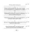
Referring to FIG. 3, a second preferred implementation manner of the present invention provides a support assembly fabricating method. The support assembly fabricating method provided in the second preferred implementation manner is similar to the support assembly fabricating method provided in the first preferred implementation manner, with a difference in that, in the second preferred implementation manner, the support assembly fabricating method further includes:
Step 105: Removing, by using a computer numerical control machine tool, sprues and burrs of the support assembly.
Step 106: Performing highlight polishing or sand blasting and brushing processing on an external surface of the appearance part, so that the external surface of the appearance part shows a metal texture.
In this preferred implementation manner, the support assembly 100 is obtained by using the support assembly fabricating method. In this preferred implementation manner, the support assembly 100 is obtained by using the support assembly fabricating method. The appearance part 41 and the internal structure support part 42 of the support assembly 100 are fabricated through integral molding of an amorphous alloy. The internal structure support part 42 is formed by extending the top or the middle of the appearance part 41 inwards. An average thickness of the internal structure support part 41 is less than 2 mm. The appearance part 41 and the internal structure support assembly 42 of the present invention do not need to be connected in a screw locking manner or welding manner, thereby simplifying a process of assembling the handheld electronic device 100.
What is disclosed above is merely an exemplary embodiment of the present invention, and definitely cannot be used to limit the protection scope of the present invention. A person skilled in the art can understand all or a part of processes that implement the foregoing embodiments and equivalent variations made in accordance with the claims of the present invention shall fall within the scope of the present invention.

Claims (16)

What is claimed is:
1. A support assembly, mounted between a rear cover and a screen of a handheld electronic device to support and fasten a component of the handheld electronic device, wherein the support assembly comprises an appearance part and an internal structure support part, wherein the appearance part and the internal structure support part are fabricated through integral molding of an amorphous alloy; the internal structure support part is formed by extending a top section or a middle section of the appearance part inwards; and an average thickness of the internal structure support part is less than 2 mm.
2. The support assembly according to claim 1, wherein a height of the appearance part ranges from 0.5 mm to 10 mm.
3. The support assembly according to claim 1, wherein the appearance part and the internal structure support part undergo one-time near net shape forming using a zirconium-based amorphous alloy die-casting or semi-solid forming process.
4. The support assembly according to claim 1, wherein a through-slot is disposed on the internal structure support part to contain a component disposed on the internal structure support part.
5. The support assembly according to claim 1, wherein an external surface of the appearance part shows a mental texture after undergoing highlight polishing or sand blasting and brushing processing.
6. The support assembly according to claim 1, wherein the amorphous alloy is a zirconium-based amorphous alloy.
7. The support assembly according to claim 1, wherein a wall thickness of the appearance part ranges from 0.5 mm to 3 mm.
8. The support assembly according to claim 1, wherein a thickness of the internal structure support part ranges from 0.2 mm to 2 mm.
9. A handheld electronic device, comprising a rear cover, a component, and a support assembly, wherein the support assembly is mounted between the rear cover and the screen to support and fasten the component, the support assembly comprises an appearance part and an internal structure support part, wherein the appearance part and the internal structure support part are fabricated through integral molding of an amorphous alloy; the internal structure support part is formed by extending a top section or a middle section of the appearance part inwards; and an average thickness of the internal structure support part is less than 2 mm.
10. The handheld electronic device according to claim 9, wherein a height of the appearance part ranges from 0.5 mm to 10 mm.
11. The handheld electronic device according to claim 9, wherein a wall thickness of the appearance part ranges from 0.5 mm to 3 mm.
12. The handheld electronic device according to claim 9, wherein a thickness of the internal structure support part ranges from 0.2 mm to 2 mm.
13. The handheld electronic device according to claim 9, wherein the appearance part and the internal structure support part undergo one-time near net shape forming by using a zirconium-based amorphous alloy die-casting or semi-solid forming process.
14. The handheld electronic device according to claim 9, wherein a through-slot is disposed on the internal structure support part to contain a component disposed on the internal structure support part.
15. The handheld electronic device according to claim 9, wherein an external surface of the appearance part shows a mental texture after undergoing highlight polishing or sand blasting and brushing processing.
16. The handheld electronic device according to claim 9, wherein the amorphous alloy is a zirconium-based amorphous alloy.
US14/465,426 2013-04-09 2014-08-21 Handheld electronic device, support assembly, and support assembly fabricating method Active US9185194B2 (en)

Priority Applications (1)

Application Number Priority Date Filing Date Title
US14/878,812 US9426263B2 (en) 2013-04-09 2015-10-08 Handheld electronic device, support assembly, and support assembly fabricating method

Applications Claiming Priority (4)

Application Number Priority Date Filing Date Title
CN201310120646.9A CN104104752B (en) 2013-04-09 2013-04-09 A kind of preparation method of hand-hold electronic equipments, support component and support component
CN201310120646 2013-04-09
CN201310120646.9 2013-04-09
PCT/CN2013/084529 WO2014166215A1 (en) 2013-04-09 2013-09-27 Handheld electronic device, support component, and method for manufacturing support component

Related Parent Applications (1)

Application Number Title Priority Date Filing Date
PCT/CN2013/084529 Continuation WO2014166215A1 (en) 2013-04-09 2013-09-27 Handheld electronic device, support component, and method for manufacturing support component

Related Child Applications (1)

Application Number Title Priority Date Filing Date
US14/878,812 Continuation US9426263B2 (en) 2013-04-09 2015-10-08 Handheld electronic device, support assembly, and support assembly fabricating method

Publications (2)

Publication Number Publication Date
US20150011271A1 US20150011271A1 (en) 2015-01-08
US9185194B2 true US9185194B2 (en) 2015-11-10

Family

ID=51672550

Family Applications (2)

Application Number Title Priority Date Filing Date
US14/465,426 Active US9185194B2 (en) 2013-04-09 2014-08-21 Handheld electronic device, support assembly, and support assembly fabricating method
US14/878,812 Active US9426263B2 (en) 2013-04-09 2015-10-08 Handheld electronic device, support assembly, and support assembly fabricating method

Family Applications After (1)

Application Number Title Priority Date Filing Date
US14/878,812 Active US9426263B2 (en) 2013-04-09 2015-10-08 Handheld electronic device, support assembly, and support assembly fabricating method

Country Status (4)

Country Link
US (2) US9185194B2 (en)
EP (1) EP2814226B1 (en)
CN (1) CN104104752B (en)
WO (1) WO2014166215A1 (en)

Families Citing this family (5)

* Cited by examiner, † Cited by third party
Publication number Priority date Publication date Assignee Title
KR102487913B1 (en) * 2015-07-01 2023-01-13 삼성전자주식회사 Method for patterning amorphous alloy, a amorphous alloy pattern structure using the same, dome switch and method for thereof
CN105328160A (en) * 2015-09-28 2016-02-17 维沃移动通信有限公司 Manufacturing method of frame for electronic equipment and electronic equipment
CN106953163B (en) * 2017-01-19 2019-11-19 瑞声科技(新加坡)有限公司 Antenna and mobile terminal
CN106936962A (en) * 2017-01-20 2017-07-07 瑞声科技(新加坡)有限公司 The shell and its manufacture method of mobile terminal
CN106898858B (en) * 2017-04-18 2019-05-31 北京小米移动软件有限公司 Forming method, shell mechanism and the electronic equipment of shell mechanism

Citations (4)

* Cited by examiner, † Cited by third party
Publication number Priority date Publication date Assignee Title
CN101577741A (en) 2008-05-09 2009-11-11 鸿富锦精密工业(深圳)有限公司 Mobile phone shell
CN102021503A (en) 2010-12-15 2011-04-20 江苏大学 Preparation method of continuous fiber reinforced metal matrix composite
CN102811264A (en) 2011-05-30 2012-12-05 李树忠 Mobile phone shell and machining method thereof
WO2013048429A1 (en) 2011-09-30 2013-04-04 Crucible Intellectual Property Llc Injection molding of amorphous alloy using an injection molding system

Family Cites Families (3)

* Cited by examiner, † Cited by third party
Publication number Priority date Publication date Assignee Title
WO2003009088A2 (en) * 2001-06-07 2003-01-30 Liquidmetal Technologies Improved metal frame for electronic hardware and flat panel displays
CN201585218U (en) * 2009-10-20 2010-09-15 国基电子(上海)有限公司 Sliding cover type electronic device
CN202856806U (en) * 2012-09-10 2013-04-03 惠州Tcl移动通信有限公司 Handset casing and handset

Patent Citations (6)

* Cited by examiner, † Cited by third party
Publication number Priority date Publication date Assignee Title
CN101577741A (en) 2008-05-09 2009-11-11 鸿富锦精密工业(深圳)有限公司 Mobile phone shell
US20090280875A1 (en) * 2008-05-09 2009-11-12 Hon Hai Precision Industry Co., Ltd. Mobile phone cover and mobile phone employing the same
CN102021503A (en) 2010-12-15 2011-04-20 江苏大学 Preparation method of continuous fiber reinforced metal matrix composite
CN102811264A (en) 2011-05-30 2012-12-05 李树忠 Mobile phone shell and machining method thereof
WO2012162909A1 (en) 2011-05-30 2012-12-06 Li Shu Chung Mobile phone shell and its processing method
WO2013048429A1 (en) 2011-09-30 2013-04-04 Crucible Intellectual Property Llc Injection molding of amorphous alloy using an injection molding system

Also Published As

Publication number Publication date
US20150011271A1 (en) 2015-01-08
EP2814226B1 (en) 2016-11-09
US9426263B2 (en) 2016-08-23
EP2814226A1 (en) 2014-12-17
WO2014166215A1 (en) 2014-10-16
CN104104752B (en) 2018-01-23
US20160028862A1 (en) 2016-01-28
CN104104752A (en) 2014-10-15
EP2814226A4 (en) 2015-04-15

Similar Documents

Publication Publication Date Title
US9426263B2 (en) Handheld electronic device, support assembly, and support assembly fabricating method
US9033024B2 (en) Insert molding of bulk amorphous alloy into open cell foam
EP3181267A1 (en) Method for integrally forming non-metal part and metal part
KR101717469B1 (en) Manufacturing Method For Metal Frame of Mobile Phone
CN104439677A (en) Amorphous alloy member and nonmetal member combination method and product
CN109133588A (en) Glass processing die and glass processing method
CN202634925U (en) Panel member for monitor and portable device with panel member
CN107598137B (en) Die casting method of metal shell and electronic equipment
CN202134582U (en) Casing structure and battery made by same
KR20160149791A (en) Metal Frame of Mobile Phone
KR101558550B1 (en) A metal-base- board of mobile that is processed by the press, its manufacture method
US20130278123A1 (en) Device housing and method for making the same
CN105101688B (en) A kind of production method of shell and shell, mobile terminal using this method production
US20170305790A1 (en) Method for integrally forming non-metal part and metal part
CN108189309A (en) A kind of production method of shatter-resistant lightweight TPU protective cases
CN107186860B (en) Ceramic member, method for manufacturing same, and electronic device
CN107900619B (en) Terminal surface cover frame and manufacturing method thereof, and mold and manufacturing method thereof
CN205414411U (en) Improve tool of powder injection molding earphone slide rail sintering warpage
JP2013179315A (en) Housing and manufacturing method of the same
CN208509263U (en) Loudspeaker mould group and sounding device
EP2684668A1 (en) Injection-moulded product and a mould and a method for manufacturing the same
CN204733205U (en) Mobile phone
CN104175567A (en) Carbon fiber treatment method and product thereof
CN211708106U (en) Injection molding machine for producing military boot soles
CN207518987U (en) Case frame structure

Legal Events

Date Code Title Description
AS Assignment

Owner name: HUAWEI TECHNOLOGIES CO., LTD., CHINA

Free format text: ASSIGNMENT OF ASSIGNORS INTEREST;ASSIGNORS:ZHU, AILAN;YANG, MINGXING;SIGNING DATES FROM 20140820 TO 20140821;REEL/FRAME:033585/0345

STCF Information on status: patent grant

Free format text: PATENTED CASE

MAFP Maintenance fee payment

Free format text: PAYMENT OF MAINTENANCE FEE, 4TH YEAR, LARGE ENTITY (ORIGINAL EVENT CODE: M1551); ENTITY STATUS OF PATENT OWNER: LARGE ENTITY

Year of fee payment: 4

MAFP Maintenance fee payment

Free format text: PAYMENT OF MAINTENANCE FEE, 8TH YEAR, LARGE ENTITY (ORIGINAL EVENT CODE: M1552); ENTITY STATUS OF PATENT OWNER: LARGE ENTITY

Year of fee payment: 8