US9181762B2 - Device for securing pipes having various diameters - Google Patents
Device for securing pipes having various diameters Download PDFInfo
- Publication number
- US9181762B2 US9181762B2 US13/511,449 US201013511449A US9181762B2 US 9181762 B2 US9181762 B2 US 9181762B2 US 201013511449 A US201013511449 A US 201013511449A US 9181762 B2 US9181762 B2 US 9181762B2
- Authority
- US
- United States
- Prior art keywords
- cylinder
- segments
- basic element
- door element
- pipes
- Prior art date
- Legal status (The legal status is an assumption and is not a legal conclusion. Google has not performed a legal analysis and makes no representation as to the accuracy of the status listed.)
- Active, expires
Links
Images


Classifications
-
- E—FIXED CONSTRUCTIONS
- E21—EARTH OR ROCK DRILLING; MINING
- E21B—EARTH OR ROCK DRILLING; OBTAINING OIL, GAS, WATER, SOLUBLE OR MELTABLE MATERIALS OR A SLURRY OF MINERALS FROM WELLS
- E21B19/00—Handling rods, casings, tubes or the like outside the borehole, e.g. in the derrick; Apparatus for feeding the rods or cables
- E21B19/02—Rod or cable suspensions
- E21B19/06—Elevators, i.e. rod- or tube-gripping devices
Definitions
- the invention relates to a device for vertically holding pipes of differing diameter for elevator systems for picking up, lifting and depositing a line of pipes or individual pipe segments onto oil platforms, consisting of a basic element for forming a cylinder liner with a swivel joint for an associated door element to complete the liner, wherein the swivel joint has a closure which is spaced apart and has a pivotable catch with a closure pin, and the closing movement is controllable via an associated hydraulic adjusting cylinder.
- cylinder segments for forming the cylinder liner in different size diameters are arranged interchangeably in the basic element and door element via rear guide profiles and associated profile rails in the basic element and door element, and the upper sides of the individual cylinder segments are connected to corresponding receptacles via retaining rings which are assigned so as to be able to be pushed on horizontally, wherein, by reception of pipes in the cylinder liner and of an occurring load, a spring-loaded actuating arm is adjustable in the height thereof via a cylinder segment, and locking of the hydraulic adjusting cylinder for the closing movement is controllable via an associated load sensor.
- the cylinder segments have additional retaining elements in the lower part for corresponding reception in the basic element and door element.
- An advantageous embodiment consists in that three cylinder segments are arranged in the basic element and two cylinder segments of the cylinder liner are arranged in the door element.
- a cylinder segment in the basic element has a protruding trigger pin which, after reception of pipes, controls the adjusting cylinder for the closing movement.
- the trigger pin is connected via a spring to a hollow piston cylinder which, after activation of the adjusting cylinder, holds the trigger pin in a drawn-back position.
- FIG. 1 shows a top view of a cylinder liner formed in the basic element and door element with a cylinder segment pulled out;
- FIG. 2 shows a view of an open cylinder liner with the cylinder segments thereof and with a connection of the cylinder segments in the upper region via retaining rings which are pushed on;
- FIG. 3 shows a partial section through a basic element with an inserted cylinder segment
- FIG. 4 shows an unloaded cylinder liner with an assigned load sensor
- FIG. 5 shows an illustration as per FIG. 4 with a loaded cylinder liner and activated load sensor
- FIGS. 6 and 7 show a cylinder liner in the unloaded and loaded state with a spring-loaded actuating arm for a load sensor
- FIG. 8 shows a top view of FIGS. 6 and 7 ;
- FIGS. 9 and 10 show a valve activation of an adjusting cylinder for closing purposes in an open and closed position
- FIGS. 11 and 12 show an assignment of a trigger pin in the basic element for the valve activation for a closing movement and as an external view with the valve in a closed arrangement;
- FIG. 13 shows a section through a cylinder segment with a trigger pin
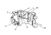
- FIG. 14 shows an overall illustration of the device in the closed position of the cylinder liner.
- the device essentially consists of a basic element 1 with a door element 3 which is pivotable via a hinge pin 2 and, in the closed state via a closure element 4 on the basic element 1 , is controllable via an adjusting cylinder 6 in order to form a cylinder liner 5 with a swivel joint 26 for the door element 3 to complete the liner 5 .
- the cylinder liner 5 is formed by individual cylinder segments 7 which are fixed interchangeably on the basic element 1 and door element 3 .
- the cylinder segments 7 are connected to rear guide profiles 8 which can be pushed into associated profile rails 9 and secured.
- the cylinder segments 7 are connected to a corresponding receptacle 21 for the cylinder segments 7 via retaining ring segments 10 which can be pushed on horizontally.
- a cylinder segment 7 is connected to a spring-loaded actuating arm 11 and, when a pipe is inserted and therefore a load occurs, acts on a load sensor 12 which, upon closure of the device, blocks the adjusting cylinder 6 .
- the load sensor 12 is an internal interlock in the hydraulic controlling means of the adjusting cylinder 6 , connecting an opening of the cylinder liner 5 and release of a load. An operator therefore receives a signal as soon as the load sensor 12 has been actuated and therefore the elevator is under load.
- the hydraulic adjusting cylinder 6 permits opening and closing of the door element 3 .
- the door element 3 can be opened by 90° in order to be able to receive pipes.
- the door element 3 rests on the basic element 1 .
- a hydraulic closure cylinder 22 is automatically actuated by a hydraulic controlling means with a valve 23 .
- the closure cylinder 22 is connected to a closure 13 with a locking pin 14 and therefore enables closing.
- the door element 3 is kept in the closed position by said closure 13 with the locking pin 14 and is connected to the basic element 1 .
- An additional locking prevents inadvertent opening of the closure should the hydraulics fail or a line break.
- three cylinder segments 7 are arranged in the basic element 1 and two cylinder segments 7 are arranged on the door element 3 .
- the cylinder segments 7 are connected on the lower side in a form-fitting manner via additional retaining elements 15 and corresponding receptacles 16 for additional guidance and securing.
- the formation of individual cylinder segments 7 in order to form the cylinder liner 5 makes it possible to reduce the weight, and the times for a change to a different pipe diameter are reduced.
- a trigger pin 17 is arranged in the central cylinder segment 7 of the basic element 1 .
- a hydraulic hollow piston cylinder 18 which is connected to the trigger pin 17 by a basic body is located level with the trigger pin 17 .
- the trigger pin 17 impacts against a cylinder rod 19 of the hollow piston cylinder 18 , presses said cylinder rod through the hollow piston cylinder 18 counter to a spring 24 and actuates a trigger valve 20 which activates the hollow piston cylinder 18 .
- the hollow piston cylinder 18 moves the cylinder rod 19 and therefore moves the trigger pin 17 away from the inserted pipe.
- the movement back of the hollow piston cylinder 18 avoids wear to the trigger pin 17 which would otherwise bear continuously against the pipe.
- the door element 3 upon actuation of the trigger valve 20 by the hydraulic controlling means, the door element 3 is automatically closed and locked.
Landscapes
- Engineering & Computer Science (AREA)
- Geology (AREA)
- Mining & Mineral Resources (AREA)
- Life Sciences & Earth Sciences (AREA)
- General Life Sciences & Earth Sciences (AREA)
- Fluid Mechanics (AREA)
- Mechanical Engineering (AREA)
- Environmental & Geological Engineering (AREA)
- Physics & Mathematics (AREA)
- Geochemistry & Mineralogy (AREA)
- Fluid-Damping Devices (AREA)
- Actuator (AREA)
- Power-Operated Mechanisms For Wings (AREA)
- Drilling And Boring (AREA)
- Lift-Guide Devices, And Elevator Ropes And Cables (AREA)
Abstract
Description
Claims (5)
Applications Claiming Priority (4)
| Application Number | Priority Date | Filing Date | Title |
|---|---|---|---|
| DE102009056393 | 2009-11-23 | ||
| DE102009056393.8 | 2009-11-23 | ||
| DE102009056393 | 2009-11-23 | ||
| PCT/DE2010/001382 WO2011060773A2 (en) | 2009-11-23 | 2010-11-23 | Device for securing pipes having various diameters |
Publications (2)
| Publication Number | Publication Date |
|---|---|
| US20120261528A1 US20120261528A1 (en) | 2012-10-18 |
| US9181762B2 true US9181762B2 (en) | 2015-11-10 |
Family
ID=44060097
Family Applications (1)
| Application Number | Title | Priority Date | Filing Date |
|---|---|---|---|
| US13/511,449 Active 2031-10-29 US9181762B2 (en) | 2009-11-23 | 2010-11-23 | Device for securing pipes having various diameters |
Country Status (5)
| Country | Link |
|---|---|
| US (1) | US9181762B2 (en) |
| EP (1) | EP2504519B1 (en) |
| CN (1) | CN102695845B (en) |
| DE (1) | DE112010004528A5 (en) |
| WO (1) | WO2011060773A2 (en) |
Cited By (2)
| Publication number | Priority date | Publication date | Assignee | Title |
|---|---|---|---|---|
| US11156038B1 (en) | 2020-08-12 | 2021-10-26 | Forum Us, Inc. | Split bowl wear bushing |
| US12607078B1 (en) | 2025-02-21 | 2026-04-21 | Forum Us, Inc. | Hydraulic spider system and methods for use thereof |
Families Citing this family (16)
| Publication number | Priority date | Publication date | Assignee | Title |
|---|---|---|---|---|
| US8979150B1 (en) | 2012-08-31 | 2015-03-17 | Gearench | Tubing elevator latch |
| CN103352665B (en) * | 2013-07-22 | 2014-08-20 | 江苏如通石油机械股份有限公司 | Oppositely-opened type hydraulic elevator with alarm device |
| US9500047B2 (en) * | 2013-07-31 | 2016-11-22 | Stingray Offshore Solutions, LLC | Method and apparatus for supporting a tubular |
| US9422778B2 (en) | 2014-03-03 | 2016-08-23 | Frank's International, Llc | Drill pipe handling system |
| DE102014110122A1 (en) | 2014-07-18 | 2016-01-21 | Mhwirth Gmbh | Device for holding a pipe segment |
| DE102014110118A1 (en) | 2014-07-18 | 2016-01-21 | Mhwirth Gmbh | Device for holding a pipe segment |
| DE102014110119A1 (en) | 2014-07-18 | 2016-01-21 | Mhwirth Gmbh | Device for holding a pipe segment |
| DE102014119181A1 (en) * | 2014-12-19 | 2016-06-23 | Mhwirth Gmbh | Method and device for picking up and lifting a pipe segment having a first longitudinal axis |
| CN106644210B (en) * | 2015-10-30 | 2022-04-22 | 中石化石油工程技术服务有限公司 | Cylindrical workpiece force measuring device |
| US10597943B2 (en) * | 2016-08-03 | 2020-03-24 | Halliburton Energy Services, Inc. | Drilling system including a driveshaft/housing lock |
| CN113316678B (en) * | 2018-11-06 | 2023-12-01 | 坎里格机器人技术有限公司 | Elevator with locking mechanism for lifting tubular members of various sizes |
| CN113330183A (en) | 2018-11-06 | 2021-08-31 | 坎里格机器人技术有限公司 | Elevator for lifting tubular pieces of various sizes with tiltable housing |
| SG11202102927TA (en) | 2018-11-06 | 2021-04-29 | Canrig Robotic Technologies As | Elevator with independent articulation of certain jaws for lifting tubulars of various sizes |
| KR20250057106A (en) * | 2018-12-20 | 2025-04-28 | 캔리그 로보틱스 테크놀로지스 에이에스 | Ex certified robotic system with enhanced corrosion resistance |
| CN112761550A (en) * | 2019-10-21 | 2021-05-07 | 江苏如通石油机械股份有限公司 | Hydraulic elevator control mechanism with function of sensing entering of tubular column |
| CN116446798B (en) * | 2023-06-14 | 2023-09-01 | 山东省地质矿产勘查开发局八〇一水文地质工程地质大队(山东省地矿工程勘察院) | Drilling equipment |
Citations (12)
| Publication number | Priority date | Publication date | Assignee | Title |
|---|---|---|---|---|
| US1664461A (en) * | 1925-09-15 | 1928-04-03 | Gustavus A Montgomery | Casing elevator |
| US2048209A (en) * | 1933-03-08 | 1936-07-21 | Nat Superior Co | Slip elevator |
| US2063378A (en) * | 1935-03-23 | 1936-12-08 | Hiniker Benjamin Franklin | Oil well spider |
| US2641816A (en) * | 1946-10-21 | 1953-06-16 | Mission Mfg Co | Power operated slip |
| US3358341A (en) * | 1966-05-23 | 1967-12-19 | Byron Jackson Inc | Pipe holding device and slip setting device therefor |
| US4275488A (en) * | 1979-01-04 | 1981-06-30 | Gray Charles E | Combined well casing spider and elevator |
| US4511168A (en) * | 1983-02-07 | 1985-04-16 | Joy Manufacturing Company | Slip mechanism |
| US4647099A (en) | 1986-02-04 | 1987-03-03 | Hughes Tool Company | Lifting head |
| EP0589823A1 (en) | 1992-09-04 | 1994-03-30 | Varco International, Inc. | Safety pipe string elevator |
| EP1726774A2 (en) | 2005-05-12 | 2006-11-29 | Weatherford/Lamb, Inc. | Equalized load distribution slips for spider and elevator |
| US20090252589A1 (en) * | 2004-05-01 | 2009-10-08 | Leendert Adriaan Marinus Sonneveld | Apparatus and method for handling pipe |
| US8079627B2 (en) * | 2006-04-28 | 2011-12-20 | Blohm + Voss Repair Gmbh | Device for vertically holding pipes |
Family Cites Families (5)
| Publication number | Priority date | Publication date | Assignee | Title |
|---|---|---|---|---|
| US1814407A (en) * | 1929-10-02 | 1931-07-14 | B A Marriner | Elevator |
| US4878705A (en) * | 1988-03-18 | 1989-11-07 | Texas Instruments Incorporated | Robot gripper passively locked |
| CN2111358U (en) * | 1991-12-03 | 1992-07-29 | 董芒德 | Electric (pneumatic) lift sub for oil well construction |
| CN2308707Y (en) * | 1997-12-11 | 1999-02-24 | 黄学宾 | Drilling rod clamping-fixing device |
| US7303021B2 (en) * | 2005-09-20 | 2007-12-04 | Varco I/P, Inc. | Wellbore rig elevator systems |
-
2010
- 2010-11-23 WO PCT/DE2010/001382 patent/WO2011060773A2/en not_active Ceased
- 2010-11-23 CN CN201080052962.1A patent/CN102695845B/en active Active
- 2010-11-23 US US13/511,449 patent/US9181762B2/en active Active
- 2010-11-23 DE DE112010004528T patent/DE112010004528A5/en not_active Withdrawn
- 2010-11-23 EP EP10805581.5A patent/EP2504519B1/en active Active
Patent Citations (12)
| Publication number | Priority date | Publication date | Assignee | Title |
|---|---|---|---|---|
| US1664461A (en) * | 1925-09-15 | 1928-04-03 | Gustavus A Montgomery | Casing elevator |
| US2048209A (en) * | 1933-03-08 | 1936-07-21 | Nat Superior Co | Slip elevator |
| US2063378A (en) * | 1935-03-23 | 1936-12-08 | Hiniker Benjamin Franklin | Oil well spider |
| US2641816A (en) * | 1946-10-21 | 1953-06-16 | Mission Mfg Co | Power operated slip |
| US3358341A (en) * | 1966-05-23 | 1967-12-19 | Byron Jackson Inc | Pipe holding device and slip setting device therefor |
| US4275488A (en) * | 1979-01-04 | 1981-06-30 | Gray Charles E | Combined well casing spider and elevator |
| US4511168A (en) * | 1983-02-07 | 1985-04-16 | Joy Manufacturing Company | Slip mechanism |
| US4647099A (en) | 1986-02-04 | 1987-03-03 | Hughes Tool Company | Lifting head |
| EP0589823A1 (en) | 1992-09-04 | 1994-03-30 | Varco International, Inc. | Safety pipe string elevator |
| US20090252589A1 (en) * | 2004-05-01 | 2009-10-08 | Leendert Adriaan Marinus Sonneveld | Apparatus and method for handling pipe |
| EP1726774A2 (en) | 2005-05-12 | 2006-11-29 | Weatherford/Lamb, Inc. | Equalized load distribution slips for spider and elevator |
| US8079627B2 (en) * | 2006-04-28 | 2011-12-20 | Blohm + Voss Repair Gmbh | Device for vertically holding pipes |
Cited By (2)
| Publication number | Priority date | Publication date | Assignee | Title |
|---|---|---|---|---|
| US11156038B1 (en) | 2020-08-12 | 2021-10-26 | Forum Us, Inc. | Split bowl wear bushing |
| US12607078B1 (en) | 2025-02-21 | 2026-04-21 | Forum Us, Inc. | Hydraulic spider system and methods for use thereof |
Also Published As
| Publication number | Publication date |
|---|---|
| CN102695845B (en) | 2015-04-22 |
| DE112010004528A5 (en) | 2012-08-30 |
| WO2011060773A2 (en) | 2011-05-26 |
| EP2504519A2 (en) | 2012-10-03 |
| US20120261528A1 (en) | 2012-10-18 |
| WO2011060773A3 (en) | 2012-03-01 |
| EP2504519B1 (en) | 2013-09-25 |
| CN102695845A (en) | 2012-09-26 |
Similar Documents
| Publication | Publication Date | Title |
|---|---|---|
| US9181762B2 (en) | Device for securing pipes having various diameters | |
| US9409755B2 (en) | Platform safety enclosure | |
| AU2010310925B2 (en) | A quick hitch coupler | |
| US20160137470A1 (en) | Lifting apparatus for lifting and lowering vehicles | |
| US8752810B2 (en) | Lockable fluid strut with frangible lock | |
| CA3171715A1 (en) | Shock absorbing retractable bollard systems | |
| US9694828B2 (en) | Operating mechanism for tank car bottom valve | |
| US10167969B1 (en) | Pressure relief valve for railroad tank cars | |
| KR101107218B1 (en) | Free Fall Release Device and Free Fall Experiment Method | |
| US20100289285A1 (en) | Apparatus for manipulating pipes | |
| CN203795993U (en) | Opening and closing device for rubbish compressor discharging door | |
| KR101276702B1 (en) | Menhole cover | |
| JP2016211203A (en) | Storage tank with telescopic slide handle | |
| US20130284454A1 (en) | Rubber element removal tool | |
| US9555676B2 (en) | Hydraulic towing system | |
| GB2293407A (en) | A crane hook having a remotely controlled ejection lever | |
| EP2546172B1 (en) | Stop member for bounding a tilting movement of a container during emptying thereof | |
| US20130038078A1 (en) | Supporting device for supporting a load to structure | |
| US20240253897A1 (en) | Door release mechanism for a container system | |
| AU2007200211B1 (en) | A Quick Release Lifting Hook | |
| EP2484854A2 (en) | Oleodynamic device for opening swing gates on sloped roads | |
| US20170175780A1 (en) | Safety Valve For The Hydraulic Hopper Lifting System Of Compactor Trucks | |
| KR101351980B1 (en) | Transport vehicles | |
| WO2010069081A1 (en) | Hose coupling safety device | |
| AU2014202859A1 (en) | Rubber Element Removal Tool |
Legal Events
| Date | Code | Title | Description |
|---|---|---|---|
| AS | Assignment |
Owner name: BLOHM + VOSS REPAIR GMBH, GERMANY Free format text: ASSIGNMENT OF ASSIGNORS INTEREST;ASSIGNORS:STOLDT, FREDERIK;BAIER, JENS;SIGNING DATES FROM 20120605 TO 20120613;REEL/FRAME:028494/0473 |
|
| AS | Assignment |
Owner name: BLOHM + VOSS OIL TOOLS GMBH, GERMANY Free format text: CHANGE OF NAME;ASSIGNOR:BLOHM + VOSS REPAIR GMBH;REEL/FRAME:029906/0810 Effective date: 20120928 |
|
| FEPP | Fee payment procedure |
Free format text: PAYOR NUMBER ASSIGNED (ORIGINAL EVENT CODE: ASPN); ENTITY STATUS OF PATENT OWNER: LARGE ENTITY |
|
| STCF | Information on status: patent grant |
Free format text: PATENTED CASE |
|
| MAFP | Maintenance fee payment |
Free format text: PAYMENT OF MAINTENANCE FEE, 4TH YEAR, LARGE ENTITY (ORIGINAL EVENT CODE: M1551); ENTITY STATUS OF PATENT OWNER: LARGE ENTITY Year of fee payment: 4 |
|
| AS | Assignment |
Owner name: US BANK, NATIONAL ASSOCIATION, TEXAS Free format text: SECURITY INTEREST;ASSIGNORS:FORUM ENERGY TECHNOLOGIES, INC.;FORUM US, INC.;GLOBAL TUBING, LLC;REEL/FRAME:053399/0930 Effective date: 20200804 |
|
| MAFP | Maintenance fee payment |
Free format text: PAYMENT OF MAINTENANCE FEE, 8TH YEAR, LARGE ENTITY (ORIGINAL EVENT CODE: M1552); ENTITY STATUS OF PATENT OWNER: LARGE ENTITY Year of fee payment: 8 |
|
| AS | Assignment |
Owner name: GLOBAL TUBING, LLC, TEXAS Free format text: RELEASE OF PATENT SECURITY AGREEMENT RECORDED AT REEL 053399/FRAME 0930;ASSIGNOR:U.S. BANK NATIONAL ASSOCIATION;REEL/FRAME:069318/0330 Effective date: 20241108 Owner name: FORUM US, INC., TEXAS Free format text: RELEASE OF PATENT SECURITY AGREEMENT RECORDED AT REEL 053399/FRAME 0930;ASSIGNOR:U.S. BANK NATIONAL ASSOCIATION;REEL/FRAME:069318/0330 Effective date: 20241108 Owner name: FORUM ENERGY TECHNOLOGIES, INC., TEXAS Free format text: RELEASE OF PATENT SECURITY AGREEMENT RECORDED AT REEL 053399/FRAME 0930;ASSIGNOR:U.S. BANK NATIONAL ASSOCIATION;REEL/FRAME:069318/0330 Effective date: 20241108 |
|
| AS | Assignment |
Owner name: NORDIC TRUSTEE AS, NORWAY Free format text: SECURITY INTEREST;ASSIGNOR:FORUM US, INC.;REEL/FRAME:069338/0347 Effective date: 20241108 |