US9166707B2 - Transmitter, signal generation device, calibration method, and signal generation method - Google Patents
Transmitter, signal generation device, calibration method, and signal generation method Download PDFInfo
- Publication number
- US9166707B2 US9166707B2 US14/131,652 US201314131652A US9166707B2 US 9166707 B2 US9166707 B2 US 9166707B2 US 201314131652 A US201314131652 A US 201314131652A US 9166707 B2 US9166707 B2 US 9166707B2
- Authority
- US
- United States
- Prior art keywords
- signal
- test signal
- correction coefficients
- coefficients
- phase
- Prior art date
- Legal status (The legal status is an assumption and is not a legal conclusion. Google has not performed a legal analysis and makes no representation as to the accuracy of the status listed.)
- Expired - Fee Related, expires
Links
- 238000000034 method Methods 0.000 title claims description 38
- 230000007274 generation of a signal involved in cell-cell signaling Effects 0.000 title claims description 23
- 238000012360 testing method Methods 0.000 claims abstract description 367
- 238000012937 correction Methods 0.000 claims abstract description 163
- 238000005259 measurement Methods 0.000 claims description 30
- 239000000284 extract Substances 0.000 claims description 5
- 238000010408 sweeping Methods 0.000 claims 1
- 230000005540 biological transmission Effects 0.000 description 20
- 238000010586 diagram Methods 0.000 description 19
- 238000001514 detection method Methods 0.000 description 16
- 230000008569 process Effects 0.000 description 16
- 239000011159 matrix material Substances 0.000 description 13
- 238000004891 communication Methods 0.000 description 10
- 238000004364 calculation method Methods 0.000 description 9
- 238000004088 simulation Methods 0.000 description 7
- 230000006870 function Effects 0.000 description 6
- 238000004458 analytical method Methods 0.000 description 5
- 230000008859 change Effects 0.000 description 4
- 238000006243 chemical reaction Methods 0.000 description 3
- 230000007423 decrease Effects 0.000 description 3
- 238000005516 engineering process Methods 0.000 description 3
- 239000000470 constituent Substances 0.000 description 2
- 230000001934 delay Effects 0.000 description 2
- 230000010354 integration Effects 0.000 description 2
- 238000004519 manufacturing process Methods 0.000 description 2
- 230000004048 modification Effects 0.000 description 2
- 238000012986 modification Methods 0.000 description 2
- 230000007420 reactivation Effects 0.000 description 2
- 230000003321 amplification Effects 0.000 description 1
- 230000008878 coupling Effects 0.000 description 1
- 238000010168 coupling process Methods 0.000 description 1
- 238000005859 coupling reaction Methods 0.000 description 1
- 230000000694 effects Effects 0.000 description 1
- 238000003199 nucleic acid amplification method Methods 0.000 description 1
- 238000013139 quantization Methods 0.000 description 1
- 238000005070 sampling Methods 0.000 description 1
- 239000004065 semiconductor Substances 0.000 description 1
- 230000008054 signal transmission Effects 0.000 description 1
Images


Classifications
-
- H04B17/0015—
-
- H—ELECTRICITY
- H04—ELECTRIC COMMUNICATION TECHNIQUE
- H04B—TRANSMISSION
- H04B17/00—Monitoring; Testing
- H04B17/10—Monitoring; Testing of transmitters
- H04B17/11—Monitoring; Testing of transmitters for calibration
-
- H—ELECTRICITY
- H04—ELECTRIC COMMUNICATION TECHNIQUE
- H04B—TRANSMISSION
- H04B17/00—Monitoring; Testing
- H04B17/10—Monitoring; Testing of transmitters
- H04B17/11—Monitoring; Testing of transmitters for calibration
- H04B17/14—Monitoring; Testing of transmitters for calibration of the whole transmission and reception path, e.g. self-test loop-back
-
- H—ELECTRICITY
- H04—ELECTRIC COMMUNICATION TECHNIQUE
- H04B—TRANSMISSION
- H04B7/00—Radio transmission systems, i.e. using radiation field
- H04B7/005—Control of transmission; Equalising
-
- H—ELECTRICITY
- H04—ELECTRIC COMMUNICATION TECHNIQUE
- H04L—TRANSMISSION OF DIGITAL INFORMATION, e.g. TELEGRAPHIC COMMUNICATION
- H04L27/00—Modulated-carrier systems
-
- H—ELECTRICITY
- H04—ELECTRIC COMMUNICATION TECHNIQUE
- H04L—TRANSMISSION OF DIGITAL INFORMATION, e.g. TELEGRAPHIC COMMUNICATION
- H04L27/00—Modulated-carrier systems
- H04L27/18—Phase-modulated carrier systems, i.e. using phase-shift keying
-
- H—ELECTRICITY
- H04—ELECTRIC COMMUNICATION TECHNIQUE
- H04L—TRANSMISSION OF DIGITAL INFORMATION, e.g. TELEGRAPHIC COMMUNICATION
- H04L27/00—Modulated-carrier systems
- H04L27/32—Carrier systems characterised by combinations of two or more of the types covered by groups H04L27/02, H04L27/10, H04L27/18 or H04L27/26
- H04L27/34—Amplitude- and phase-modulated carrier systems, e.g. quadrature-amplitude modulated carrier systems
- H04L27/36—Modulator circuits; Transmitter circuits
- H04L27/362—Modulation using more than one carrier, e.g. with quadrature carriers, separately amplitude modulated
- H04L27/364—Arrangements for overcoming imperfections in the modulator, e.g. quadrature error or unbalanced I and Q levels
Definitions
- This disclosure relates to a transmitter, a signal generation device, a calibration method, and a signal generation method.
- the disclosure relates to calibration of frequency characteristics in a transmitter and an IQ signal calibration technique in a transmitter.
- a frequency characteristics correcting device disclosed in Patent document 1 is known as a device for correcting signal distortion.
- the frequency characteristics correcting device of Patent document 1 in signal transmission by a transmission system circuit, part of a transmission signal is extracted by a coupling circuit and divided into a low-frequency portion and a high-frequency portion by respective band division filters and outputs (power levels) of the respective filters are detected by respective power detectors. Furthermore, in the frequency characteristics correcting device, a variable equalizer circuit is controlled on the basis of a voltage that is obtained by comparing outputs of the respective power detectors by a comparison circuit.
- Patent document 1 JP-A-2001-16145
- an object of the present invention is to provide a transmitter, a signal generation device, a calibration method, and a signal generation method which can correct signal distortion with high accuracy.
- a transmitter comprising a test signal generator for generating a test signal; a frequency characteristics corrector for correcting an amplitude characteristic and a phase characteristic of the test signal generated by the test signal generator; a modulator for modulating a corrected signal produced by the frequency characteristics corrector through the correction; an envelope detector for detecting an envelope of a modulated signal produced by the modulator through the modulation; a frequency characteristics calculator for calculating frequency characteristics of an envelope signal detected by the envelope detector; and a coefficients calculator for calculating, on the basis of the frequency characteristics calculated by the frequency characteristics calculator, correction coefficients to be used by the frequency characteristics corrector to correct the amplitude characteristic and the phase characteristic of the test signal, wherein the test signal generator generates a test signal in which signal loci in each of at least two pairs of quadrants of first to fourth quadrants of the IQ plane are not symmetrical with each other.
- the disclosure makes it possible to correct signal distortion with high accuracy.
- FIG. 1 is a block diagram showing an example configuration of a transmitter according to a first embodiment of this disclosure.
- FIGS. 2(A) , 2 (B), and 2 (D) show example test signals generated by a test signal generator used in the first embodiment of the disclosure, and FIG. 2(C) shows a phase characteristic of a test signal.
- FIG. 3 shows an example relationship between components, having respective angular frequencies, of a test signal and their amplitudes in the first embodiment of the disclosure.
- FIG. 4 is a block diagram showing an example detailed configuration of a frequency characteristics corrector used in the first embodiment of the disclosure.
- FIG. 5 is a flowchart of a first example operation for calculating correction coefficients in the transmitter according to the first embodiment of the disclosure.
- FIG. 6 is a flowchart of a second example operation for calculating correction coefficients in the transmitter according to the first embodiment of the disclosure.
- FIG. 7 is a flowchart of a third example operation for calculating correction coefficients in the transmitter according to the first embodiment of the disclosure.
- FIG. 8 shows a simulation result of an amplitude characteristic of a test signal in the first embodiment of the disclosure.
- FIG. 9 shows a simulation result of an amplitude characteristic of the test signal in the first embodiment of the disclosure.
- FIG. 10 is a flowchart of a fourth example operation for calculating correction coefficients in the transmitter according to the first embodiment of the disclosure.
- FIG. 11 is a graph showing an image of correction of the phase characteristic of a test signal into a linear phase characteristic in the first embodiment of the disclosure.
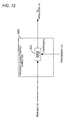
- FIG. 12 is a block diagram showing a modified configuration of the frequency characteristics corrector used in the first embodiment of the disclosure.
- FIG. 13 is a block diagram showing an example configuration of a first wireless apparatus according to the first embodiment of the disclosure.
- FIG. 14 is a block diagram showing an example configuration of a second wireless apparatus according to the first embodiment of the disclosure.
- FIG. 15 is a block diagram of a transmitter according to a second embodiment of the disclosure.
- FIG. 16 is a block diagram showing an example detailed configuration of an IQ imbalance corrector used in the second embodiment of the disclosure.
- FIG. 17 is a block diagram showing an example detailed configuration of a modulator used in the second embodiment of the disclosure.
- FIGS. 18(A) and 18(B) show examples of a first test signal and a second test signal in the IQ plane in the second embodiment of the disclosure.
- FIG. 19 shows an example input/output characteristic of an envelope detector used in the second embodiment of the disclosure.
- FIG. 20 is a flowchart showing an example operation of a calculator used in the second embodiment of the disclosure.
- FIG. 21 is a table showing an example relationship between the detected phase and the IQ imbalance direction in the second embodiment of the disclosure.
- FIG. 22 is a block diagram showing an example configuration of a first wireless apparatus according to the second embodiment of the disclosure.
- FIG. 23 is a block diagram showing an example configuration of a second wireless apparatus according to the second embodiment of the disclosure.
- signal distortion that depends on the frequency used tends to appear in an analog circuit including a frequency converter which performs frequency conversion of a baseband signal and a high-frequency signal, a power amplifier, and an LNA unit.
- a frequency converter which performs frequency conversion of a baseband signal and a high-frequency signal
- a power amplifier and an LNA unit.
- millimeter wave communication that handles frequencies in a wide band (e.g., 60 GHz band)
- the communication characteristics may be degraded to a large extent because of a wide signal band.
- FIG. 1 is a block diagram showing an example configuration of a transmitter 100 according to a first embodiment of the disclosure.
- the transmitter 100 is equipped with a test signal generator 101 , a data generator 102 , an MUX (multiplexer) 103 , a frequency characteristics corrector 104 , a modulator 105 , an envelope detector 106 , a frequency characteristics calculator 107 , a coefficients calculator 108 , and a memory 109 .
- the test signal generator 101 generates a test signal for measurement of distortion produced by the transmitter 100 , and outputs it to the MUX 103 .
- a test signal generation method will be described later in detail.
- the data generator 102 generates a baseband signal containing data to be transmitted and outputs it to the MUX 103 .
- the data to be transmitted contains musical data or video data.
- the MUX 103 selects the output of the test signal generator 101 or that of the data generator 102 , and outputs the selected signal to the frequency characteristics corrector 104 . More specifically, the MUX 103 selects the output (test signal) of the test signal generator 101 in a calibration mode, and selects the output (baseband signal) of the data generator 102 in a data transmission mode. The MUX 103 also selects a mode in which to specify an operation of the transmitter 100 .
- the frequency characteristics corrector 104 corrects the frequency characteristics of the output signal of the MUX 103 on the basis of parameters (correction coefficients) stored in an LUT (lookup table) which is held by the memory 109 , and outputs a resulting corrected signal to the modulator 105 .
- the frequency characteristics include an amplitude characteristic and a phase characteristic.
- the modulator 105 modulates the corrected signal that is output from the frequency characteristics corrector 104 , and outputs a resulting modulated signal (high-frequency signal).
- the frequency is 60 GHz, for example.
- the envelope detector 106 is equipped with an envelope detector 106 A and an AD converter 1066 which is disposed downstream of the envelope detector 106 A so as to be connected to it in series.
- the envelope detector 106 A which is formed by using a wave detection diode, detects an envelope of the high-frequency signal that is output from the modulator 105 .
- the envelope detector 106 A receives part of the output energy of the high-frequency signal and detects the magnitude of an envelope of the high-frequency signal.
- a detected signal of the envelope detector 106 A is given by the following Formula (2): [Formula 2] c
- Symbol c represents a constant.
- the AD converter 106 B converts the analog signal as the envelope detection result into a digital signal, and outputs the digital signal (envelope signal) to the frequency characteristics calculator 107 .
- the frequency characteristics calculator 107 receives the signal (envelope signal) detected by the envelope detector 106 , and calculates frequency characteristics of the envelope signal.
- the coefficients calculator 108 calculates correction coefficients for correction of the frequency characteristics (amplitude characteristic and phase characteristic) of the test signal on the basis of the frequency characteristics calculated by the frequency characteristics calculator 107 .
- the coefficients calculator 108 stores the calculated correction coefficients in the LUT which is held by the memory 109 .
- the frequency characteristics calculator 107 and the coefficients calculator 108 realize their functions by running programs that are stored in the memory 109 . How the frequency characteristics calculator 107 and the coefficients calculator 108 operate will be described later in detail.
- the transmitter 100 may be implemented by using a first integrated circuit and a second integrated circuit.
- the first integrated circuit includes the test signal generator 101 , the data generator 102 , the MUX 103 , the frequency characteristics corrector 104 , the frequency characteristics calculator 107 , the coefficients calculator 108 , and the memory 109 .
- the second integrated circuit includes the modulator 105 and the envelope detector 106 .
- all the constituent units of the transmitter 100 may be implemented as a single integrated circuit.
- a detection system including the envelope detector 106 , frequency characteristics calculator 107 , and the coefficients calculator 108 operates.
- test signal generator 101 Next, the test signal generator 101 will be described.
- test signal generator 101 generates a test signal S that is represents by the following Equations (3):
- Equations (3) ⁇ m, n is the angular frequency, d is a constant indicating an offset amount, and K is a constant representing the amplitude.
- the frequency of the test signal S is 100 MHz or 500 MHz. That is, the angular frequency ⁇ m, n in Equation (3) is sufficiently lower than the angular frequency ⁇ in Equation (1).
- FIG. 2(A) is a diagram in which the test signal S of Equation (3) is shown in the IQ plane.
- the test signal S is represented by a circle that is offset by the distance d from a circle C whose center is located at the origin O of the IQ plane and that is the same in amplitude as the test signal S.
- the test signal S may rotate at a constant speed along the circle but need not always do so.
- the test signal generator 101 may generate, as a test signal, an IQ signal that is not given by Equations (3).
- the test signal generator 101 may generate an IQ signal that is symmetrical with respect to the I axis (see FIG. 2(B) ) or the Q axis.
- the test signal generator 101 may generate an IQ signal that is obtained by rotating an IQ signal that is symmetrical with respect to the I axis or the Q axis about the origin O of the IQ plane. Also in these cases, the center of the test signal S is offset by a prescribed amount from the origin O. The test signal S may rotate at a constant speed along the line but need not always do so.
- the I axis and the Q axis are examples of a reference axis.
- test signal shown in FIG. 2(A) or 2 (B) is generated by the test signal generator 101 , it has such a characteristic that as shown in FIG. 2(C) its amplitude varies monotonously as its phase varies from ⁇ to ⁇ +180°, ⁇ being a phase of its line of symmetry (the reference axis passing through the origin).
- ⁇ being a phase of its line of symmetry (the reference axis passing through the origin).
- FIG. 2(D) is different from that of FIG. 2(B) in that the line of symmetry has a phase ⁇ .
- the loci of the test signal in each of at least two pairs of quadrants of the first to fourth quadrants of the IQ plane be not symmetrical with each other.
- the loci in the first and second quadrants is not symmetrical with each other
- the loci in the first and third quadrants is not symmetrical with each other
- the loci in the second and fourth quadrants is not symmetrical with each other
- the loci in the first and fourth quadrants is symmetrical with each other
- the loci in the second and third quadrants is symmetrical with each other.
- the loci in the first and second quadrants is not symmetrical with each other, the loci in the first and third quadrants is not symmetrical with each other, the loci in the second and fourth quadrants is not symmetrical with each other, the loci in the first and fourth quadrants is symmetrical with each other, and the loci in the second and third quadrants is symmetrical with each other.
- test signal C shown in FIG. 2(A) with which the circle having the center at the origin is drawn in the IQ plane is used, the magnitude of an envelope detected by the envelope detector 106 is constant. Therefore, this test signal C does not have an AC signal component and hence it is difficult to obtain its phase characteristic.
- the magnitude of an envelope can be varied when the test signal generator 101 generates a test signal S that is offset from the origin by a prescribed amount. Therefore, an amplitude characteristic and a phase characteristic can be acquired by using such a test signal S.
- FIG. 3 shows an example relationship between components, having the angular frequencies ⁇ m, n , of the test signal S and their amplitudes.
- test signal having an angular frequency ⁇ m, 1 is used as a first test signal S 1 and a test signal having an angular frequency ⁇ m, n is used as an nth test signal S n .
- test signal having an angular frequency ⁇ m, N is used as an Nth test signal S N .
- the test signal S n is a component, having the angular frequency ⁇ m, n , of the test signal S.
- the value N is the number of samples for determining frequency characteristics of the test signal S n . It is preferable that the test signal generator 101 set the value N taking into consideration at what frequency interval frequency characteristics are to be analyzed and at what resolution frequency characteristics are to be corrected. The value N may be set in advance.
- FIG. 4 is a block diagram showing an example detailed configuration of the frequency characteristics corrector 104 .
- the frequency characteristics corrector 104 is equipped with a Fourier transformer 204 , a multiplier 205 , and an inverse Fourier transformer 206 .
- the Fourier transformer 204 converts a time-domain signal which is an output signal of the MUX 103 into a frequency-domain signal. Since the output signal of the MUX 103 is an IQ signal, the Fourier transformer 204 converts it as complex data.
- the Fourier transformer 204 performs fast Fourier transform (FFT), for example.
- the multiplier 205 multiples the frequency-domain signal that is output from the Fourier transformer 204 by correction coefficients that are stored in the LUT held by the memory 109 .
- the inverse Fourier transformer 206 converts the frequency-domain signal that is output from the multiplier 205 into a time-domain signal.
- the inverse Fourier transformer 206 performs inverse fast Fourier transform (IFFT), for example.
- IFFT inverse fast Fourier transform
- FIG. 5 is a flowchart of a first example operation for calculating correction coefficients for correction of frequency characteristics on the basis of a test signal S in the transmitter 100 .
- the example of FIG. 5 assumes that coefficients z n of the respective angular frequencies ⁇ m, n are calculated by one frequency sweep.
- the coefficients z n are correction coefficients.
- test signal generator 101 sets variable n to an initial value “1” (step S 401 ).
- the test signal generator 101 then generates a test signal S and sets its angular frequency to the angular frequency ⁇ m, n (step S 402 ).
- the frequency characteristics corrector 104 does not perform frequency characteristics correction or performs frequency characteristics correction by setting the coefficients z n stored in the LUT to “1.”
- the frequency characteristics calculator 107 receives an envelope signal corresponding to a test signal S n having the angular frequency ( ⁇ m, n and Fourier-transforms it (step S 403 ). That is, the frequency characteristics calculator 107 has a Fourier transformer. To increase the calculation efficiency, the frequency characteristics calculator 107 uses fast Fourier transform (FFT), for example.
- FFT fast Fourier transform
- the frequency characteristics calculator 107 then extracts component complex data a n +jb n of the angular frequency ⁇ m, n in the IQ plane (step S 404 ).
- frequency characteristics including an amplitude characteristic and a phase characteristic, of the component of the angular frequency ⁇ m, n are obtained by executing step S 404 .
- the frequency characteristics are of the transmitter 100 itself and, more specifically, are frequency characteristics of distortion that originates from, for example, the analog circuit of the transmitter 100 .
- the coefficients calculator 108 calculates a coefficient z n which is complex data for correction of the frequency characteristics of the transmitter 100 , and has the information of the coefficient z n held inside the coefficients calculator 108 temporarily (step S 405 ).
- the coefficient 4 is given by the following Equation (6):
- the coefficient z n is also given by the following Equation (7) using the amplitude m n and the phase ⁇ n :
- the coefficients calculator 108 calculates a coefficient z n which is the reciprocal of the complex data a n +jb n of the angular frequency ⁇ m, n of the test signal S.
- the coefficient z n is an inverse characteristic of the frequency characteristic of the transmitter 100 .
- test signal generator 101 judges whether or not the sweep has reached the test signal S N which is the last angular frequency component (step S 406 ). That is, the test signal generator 101 judges whether n ⁇ N is satisfied or not.
- test signal generator 101 changes the angular frequency ⁇ m, n of the test signal S n (step S 407 ). That is, “1” is added to variable n. The process then returns to step S 402 .
- the coefficients calculator 108 stores, in the LUT held by the memory 109 , the information of coefficients z n of the respective angular frequencies ⁇ m, 1 to ⁇ m, N which are held therein temporarily (step S 408 ).
- frequency component of test signals S n of the respective angular frequencies ⁇ m, n are analyzed and coefficients z n are calculated, whereby the frequency characteristics can be corrected in such a manner that an amplitude characteristic and a phase characteristic of the test signals S n are taken into consideration. Since a modulated signal is generated from a corrected baseband signal, a signal having a flat amplitude characteristic and phase characteristic can be transmitted. Furthermore, since an inverse characteristic can be calculated easily because the reciprocal of a frequency characteristic of the transmitter 100 is used.
- coefficients z n of all the angular frequencies ⁇ m, 1 to ⁇ m, n are calculated and then stored in the memory 109 . That is, the coefficients calculator 108 stores calculated coefficients z n in the LUT after a sweep of the N angular frequencies ⁇ m, n of the test signals S n . Alternatively, the coefficients calculator 108 may store a coefficient z n of each angular frequency ⁇ m, n in the memory 109 every time it is calculated.
- FIG. 6 is a flowchart of a second example operation for calculating correction coefficients for correction of frequency characteristics on the basis of a test signal S in the transmitter 100 .
- coefficients z n of the respective angular frequencies ⁇ m, n are calculated repeatedly
- coefficients y n which are based on the coefficients z n are stored in the LUT.
- the coefficients z n are updated successively.
- the coefficients z n are coefficients indicating residual errors of correction and are coefficients for calculation of coefficients y n .
- the coefficients yn are correction coefficients.
- a coefficient w is a weighting coefficient in adding residual errors z n and is selected from a range of 0 to 1. For example, the coefficient w is set at 0.5.
- test signal generator 101 sets variable n to an initial value “1” and sets variables y n to initial values “0” (step S 501 ).
- the transmitter 100 executes the same steps S 402 -S 406 as shown in FIG. 5 .
- the process moves to step S 502 .
- the coefficients calculator 108 stores the information of the calculated coefficients y n in the LUT which is held by the memory 109 . If the LUT is already stored with information of coefficients y n , it is updated by the new information.
- the coefficients calculator 108 then calculates differences between the current coefficients y n with the coefficients y n calculated last time. The process is finished if the differences are smaller than or equal to a predetermined threshold value. The process returns to step S 402 if the differences are larger than the predetermined threshold value (step S 504 ).
- the coefficients calculator 108 updates the coefficients y n stored in the LUT while calculating coefficients y n as correction coefficients repeatedly. For example, the coefficients y n are updated by a result of adding weighted coefficients z n to them.
- the correction accuracy of the coefficients y n as correction coefficients is increased because coefficients z n of the respective angular frequency ⁇ m, n are calculated repeatedly. Since coefficients z n are calculated repeatedly and coefficients y n are calculated using the coefficient w, residual errors come closer to zero gradually and the correction accuracy is increased further.
- a modulated signal is generated from a corrected baseband signal, a signal having a flat amplitude characteristic and phase characteristic can be transmitted.
- FIG. 7 is a flowchart of a third example operation for calculating correction coefficients for correction of frequency characteristics on the basis of a test signal S in the transmitter 100 . Differences from the process of FIG. 6 will be described.
- coefficients z n of the respective angular frequency ⁇ m, n are calculated repeatedly R times.
- the test signal generator 101 sets variable n to an initial value “1,” sets variables y n to initial values “0,” and sets variable r to an initial value “1.”
- the coefficients calculator 108 judges whether or not coefficients y n have been calculated a prescribed number of times (R times). More specifically, the coefficients calculator 108 judges whether r ⁇ R is satisfied or not.
- step S 507 the coefficients calculator 108 adds “1” to variable r and initializes variable n to “1.” On the other hand, if it is judged that coefficients y n have been calculated R times, the transmitter 100 finishes the process of FIG. 7 .
- FIG. 8 shows a simulation result of an amplitude characteristic of a test signal.
- FIG. 9 shows a simulation result of a phase characteristic of the test signal.
- FIGS. 8 and 9 show results of a simulation performed according to the operation of FIG. 5 , 6 , or 7 .
- the test signal generator 101 sets the sampling frequency to 3.52 GHz and sets the coefficients K and d used in Equations (3) to 1 and 0.1, respectively.
- a second-order Butterworth filter in which the cutoff frequency is 300 MHz and the pass frequency is shifted to the negative direction by 352 MHz is assumed as a filter that simulates the frequency characteristics of the transmitter 100 .
- the solid line L 1 represents a characteristic of the filter and white circles D 1 represent a frequency characteristic (detected characteristic) of the test signal measured by the frequency characteristics calculator 107 . It is seen from FIGS. 8 and 9 that the filter characteristic and the detected characteristic coincide with each other. Therefore, it is confirmed that an amplitude characteristic and a phase characteristic can be detected accurately by the detection system of the transmitter 100 .
- the broken line L 2 represents a frequency characteristic (corrected characteristic) of a signal as corrected by the frequency characteristics corrector 104 after calculation of correction coefficients.
- the broken line L 2 representing a phase characteristic coincides with the line of “0.” That is, when a signal is corrected by the frequency characteristics corrector 104 using correction coefficients which represent an inverse characteristic and a resulting corrected signal is modulated, a signal to be transmitted comes to have a flat phase characteristic and amplitude characteristic.
- frequency characteristics can be analyzed properly even for a filter characteristic that is offset from the center of a measurement frequency range and is not symmetrical.
- FIG. 10 is a flowchart is a flowchart of a fourth example operation for calculating correction coefficients for correction of frequency characteristics on the basis of a test signal S in the transmitter 100 .
- coefficients x n are correction coefficients.
- correction is made so as to attain a linear phase characteristic instead of making correction until a signal that is output from the transmitter 100 exhibits a flat phase characteristic (equivalent to the characteristic represented by the broken line L 2 in FIG. 9 ).
- step S 601 upon completion of Fourier transform on a test signal of an angular frequency ⁇ m, n .
- the frequency characteristics calculator 107 extracts component complex data a n +jb n of the angular frequency ⁇ m, n the IQ plane.
- the frequency characteristics calculator 107 calculates an amplitude m n and a phase ⁇ n from the extracted data a n +jb n according to Equations (4) and (5), respectively (step S 601 ).
- the linear phase characteristic ⁇ i, n is a characteristic that the phase decreases linearly as the frequency increases (see FIG. 11 ).
- the information of the linear phase characteristic ⁇ i, n is held by the memory 109 in advance.
- the coefficients calculator 108 then calculates a coefficient x n which is complex data for correction of the frequency characteristics of the transmitter 100 , and has the information of the coefficient x n held inside the coefficients calculator 108 temporarily (step S 405 ).
- the coefficient x n is given by the following Equation (8) using the amplitude m n and the phase difference ⁇ n :
- the coefficients calculator 108 calculates a coefficient x n as a correction coefficient on the basis of the amplitude m n and the difference between the phase ⁇ n of the component complex data and the linear phase characteristic ⁇ i, n of the angular frequency ⁇ m, n of the test signal S and the linear phase characteristic ⁇ i, n .
- the phase of the test signal delays more as the frequency increases (see FIG. 9 ) because its transmission system usually has a positive delay time.
- the transmission system includes the test signal generator 101 , the data generator 102 , the MUX 103 , the frequency characteristics corrector 104 , and the modulator 105 .
- the process of FIG. 10 can produce such coefficients x n that the phase characteristic is made close to a linear phase characteristic taking a certain degree of phase delay into consideration instead of producing a characteristic that is completely inverse in phase to the frequency characteristics of the transmitter 100 . Therefore, the transmitter 100 can produce a satisfactory amplitude characteristic and phase characteristic without the need for preparing a filter having a negative delay time.
- the amount of calculation can be made smaller than in the case of generating correction amounts of an inverse characteristic, which enables effective use of a time resource and a bit width resource. Therefore, even in the case where a frequency characteristic having steep variations at particular frequencies as in quantization noise is included, the correction accuracy can be increased by making correction into a linear phase characteristic by using one parameter ( ⁇ n ).
- FIG. 11 is a graph showing an image of correction of the phase characteristic of a test signal into a linear phase characteristic.
- the solid line L 1 represents a filter characteristic of a filter that simulates the frequency characteristics of the transmitter 100 .
- White dots D 1 represent a detected characteristic.
- the broken line L 2 represents a linear phase characteristic, that is, a corrected characteristic as corrected using coefficients x n calculated at prescribed frequencies by the process of FIG. 10 .
- FIG. 12 is a block diagram showing a modified configuration of the frequency characteristics corrector 104 .
- the frequency characteristics corrector 104 is equipped with a digital filter 301 .
- coefficients of the digital filter 301 are stored in the LUT.
- coefficients of the digital filter 301 may be calculated by inverse-Fourier-transforming coefficients z n (correction coefficients) in the coefficients calculator 108 .
- the configuration can be simplified because it is not necessary that the frequency characteristics corrector 104 be provided with a Fourier transformer and an inverse Fourier transformer.
- the transmitter 100 finishes the calibration mode. Upon the finish of the calibration mode, the transmitter 100 switches to the data transmission mode. More specifically, the MUX 103 shown in FIG. 1 selects the output of the data generator 102 .
- the frequency characteristics corrector 104 corrects an IQ signal that is output from the data generator 102 by referring to the LUT in which the correction coefficients calculated by the coefficients calculator 108 are stored. Subsequently, the modulator 105 modulates a corrected signal and a modulated signal is transmitted.
- the transmitter 100 can correct the amplitude characteristic and the phase characteristic of a signal with high accuracy and hence can reduce distortion of a transmission signal.
- the correction of the frequency characteristics of the transmitter 100 is performed at the time of power-on of the transmitter 100 or its reactivation from a sleep mode or before the start of a data transmission.
- the transmitter 100 can correct, with high accuracy, frequency characteristics caused by frequency conversion between a baseband signal and a high-frequency signal in, for example, wireless communications in a wide frequency band. Furthermore, a transmitter can be realized in which an amplitude characteristic, a phase characteristic, and frequency characteristics are compensated so as to become flat in wireless communications in a wide frequency band.
- FIG. 13 is a block diagram showing an example configuration of the wireless apparatus 400 .
- the wireless apparatus 400 is equipped with the transmitter 100 , a receiver 402 , a duplexer 403 , and an antenna 404 .
- the transmitter 100 corrects frequency characteristics, modulates desired data, and transmits a modulated signal.
- the receiver 402 receives data from another communication apparatus.
- the duplexer 403 separates a transmission signal and a reception signal from each other, whereby the antenna 404 is shared by transmission and reception.
- the wireless apparatus 400 makes it possible to transmit data having only a low degree of distortion.
- FIG. 14 shows another wireless apparatus 500 which is equipped with a transmission antenna 503 and a reception antenna 504 which are separate from each other.
- conventional transmitters modulate a transmission signal using an I signal and a Q signal (also called an IQ signal) and output a modulated signal.
- the modulation accuracy should be high if the I signal and the Q signal have a phase different of 90° and the same amplitude.
- transmitters include an analog circuit, an I signal and a Q signal are different from each other in amplitude and their phase difference may deviate from 90°.
- Transmitters calibrate an IQ signal in the digital domain to make it closer to a desired state.
- This transmitter uses a sinusoidal single-sideband signal as a test signal. An envelope-detected signal is subjected to a frequency analysis and a phase of a frequency-analyzed signal is determined. The transmitter determines directivity of a gain error and a phase error from the thus-determined phase and performs calibration (refer to Referential patent document, for example).
- An envelope detector which detects an envelope of a signal is used for calibrating an IQ signal.
- the envelope detector is formed using a wave detection diode, for example.
- an AD (analog-to-digital) converter which receives an output of the envelope detector is disposed downstream of the envelope detector.
- the modulation frequency of the AD converter can be set low and the number of bits that can be handled by the AD converter (dynamic range, vertical resolution) can be increased.
- the number of bits that can be handled can be increased as the frequency band becomes narrower because a tradeoff relationship exists between the frequency band of an input signal and the number of bits. Therefore, it is highly probable that a signal in a relatively narrow frequency band can be detected correctly.
- a transmitter, a signal generation device, and a signal generation method which can increase the IQ calibration accuracy will be hereinafter described.
- FIG. 15 is a block diagram showing an example configuration of a transmitter 1100 according to a second embodiment of the disclosure.
- the transmitter 1100 is equipped with a test signal generator 1101 , a baseband signal generator 1102 , an MUX (multiplexer) 1103 , an IQ imbalance corrector 1104 , a modulator 1105 , an envelope detector 1106 , a calculator 1107 , and a memory 1108 .
- the test signal generator 1101 generates a test signal for measurement of IQ imbalance and outputs it to the MUX 103 .
- the test signal generator 1101 generates a test signal according to a detectable range of the envelope detector 1106 . A test signal generation method will be described later in detail.
- the baseband signal generator 1102 generates a baseband signal to be used for a communication and outputs it to the MUX 1103 .
- the MUX 1103 selects the test signal or the baseband signal, and outputs the selected signal to the IQ imbalance corrector.
- the MUX 1103 selects the output of the test signal generator 1101 in a calibration mode (i.e., in calibrating the IQ signal), and selects the output of the baseband signal generator 1102 in a data transmission mode (i.e., in transmitting the baseband signal).
- the IQ imbalance corrector 1104 corrects the received IQ signal on the basis of parameters (correction coefficients) stored in an LUT (lookup table) which is held by the memory 1108 , and outputs a resulting corrected signal to the modulator 1105 .
- IQ imbalance is corrected in the correction performed by the IQ imbalance corrector 1104 .
- the IQ imbalance includes an amplitude error and a phase error.
- the modulator 1105 modulates the corrected signal that is output from the IQ imbalance corrector 1104 , and outputs a resulting modulated signal (high-frequency signal).
- the envelope detector 1106 includes an envelope detector 1106 A and an AD converter 1106 B which is disposed downstream of the envelope detector so as to be connected to it in series.
- the envelope detector 1106 A which is formed by using a wave detection diode, detects an envelope of the high-frequency signal that is output from the modulator 1105 .
- the AD converter 1106 B converts the analog signal as the envelope detection result into a digital signal, and outputs the digital signal (envelope signal) to the calculator 1107 .
- the calculator 1107 detects IQ imbalance by analyzing the envelope signal. And the calculator 1107 calculates correction coefficients for correction of the IQ imbalance and updates the LUT which is held by the memory 1108 . That is, the calculator 1107 has a function of a correction coefficients processor for calculating correction coefficients on the basis of the envelope detected by the envelope detector 1106 .
- the calculator 1107 realizes its functions by running programs that are stored in a memory (not shown). How the calculator 1107 operates will be described later in detail.
- the memory 1108 has the LUT and stores various data and parameters.
- the various parameters include a matrix c which includes correction coefficients.
- test signal generator 1101 , the baseband signal generator 1102 , the MUX 1103 , the IQ imbalance corrector 1104 , the calculator 1107 , and the memory 1108 may be implemented as a first integrated circuit, and the modulator 1105 and the envelope detector 1106 may be implemented as a second integrated circuit. Alternatively, all the constituent units of the transmitter 1100 may be implemented as a single integrated circuit.
- the matrix c which is used for the IQ imbalance correction is given by the following Equation (9) which uses values g c and ⁇ c .
- the value g c is a value to contribute to correction of an amplitude error g e
- the value ⁇ c is a value to contribute to correction of a phase error ⁇ e .
- Equation (10) When the amplitude error g e and the phase error ⁇ e are sufficiently small, the values g c and ⁇ c also become small and the matrix c can be approximated by the following Equation (10):
- FIG. 16 is a block diagram showing an example detailed configuration of the IQ imbalance corrector 1104 .
- the IQ imbalance corrector 1104 includes multipliers 1201 , 1202 , 1203 , and 1204 and adders 1205 and 1206 .
- the multiplier 1201 receives an I signal (pre-correction I signal) that is output from the MUX 1103 and a correction coefficient c(1, 1) that is stored in the LUT, and multiplies them together.
- the multiplier 1202 receives the I signal (pre-correction I signal) that is output from the MUX 1103 and a correction coefficient c(2, 1) that is stored in the LUT, and multiplies them together.
- the multiplier 1203 receives a Q signal (pre-correction Q signal) that is output from the MUX 1103 and a correction coefficient c(1, 2) that is stored in the LUT, and multiplies them together.
- the multiplier 1204 receives the Q signal (pre-correction Q signal) that is output from the MUX 1103 and a correction coefficient c(2, 2) that is stored in the LUT, and multiplies them together.
- the adder 1205 receives outputs of the multipliers 1201 and 1203 and outputs a corrected I signal (post-correction I signal).
- the adder 1206 receives outputs of the multipliers 1202 and 1204 and outputs a corrected Q signal (post-correction Q signal).
- FIG. 17 is a block diagram showing an example detailed configuration of the modulator 1105 .
- the modulator 1105 includes multipliers 1301 and 1302 , an oscillator 1303 , and an adder 1304 .
- the multiplier 1301 receives the corrected I signal (post-correction I signal) that is output from the IQ imbalance corrector 1104 and an output of the oscillator 1303 , and multiplies them together.
- the multiplier 1302 receives the corrected Q signal (post-correction Q signal) that is output from the IQ imbalance corrector 1104 and an output of the oscillator 1303 , and multiplies them together.
- the oscillator 1303 generates a continuous wave signal, gives a phase difference of 90° to two continuous wave signals, and supplies the resulting signals to the respective multipliers 1301 and 1302 .
- the adder 1304 receives outputs of the multipliers 1301 and 1302 and adds them together.
- An output of the adder 1304 is a modulated signal, that is, an output signal of the transmitter 1100 .
- an amplifier may be provided downstream of the modulator 1105 .
- the output signal of the transmitter 1100 is given by the following Equation (11) which uses the amplitude error g e and the phase error ⁇ e .
- V A O ⁇ ( ( 1 - g e ) ⁇ I ⁇ ⁇ e j ⁇ ⁇ ⁇ c 2 + j ⁇ ( 1 + g e ) ⁇ Q ⁇ ⁇ e - j ⁇ ⁇ ⁇ e 2 ) ⁇ e j ⁇ ⁇ ⁇ ⁇ ⁇ t ( Formula ⁇ ⁇ 11 )
- test signal generator 1101 Next, the test signal generator 1101 will be described.
- test signals There are two kinds of test signals, that is, a first test signal S 10 and a second test signal S 20 .
- the first test signal S 10 is a signal for measurement of a reference phase of a signal generated by the transmitter 1100 .
- the second test signal S 20 is a signal for measurement of a measurement phase of the signal generated by the transmitter 1100 .
- the test signal generator 1101 outputs, as the first test signal S 10 , a first test signal S 11 which is given by the following Equations (12) and is a signal for determination of a reference phase of 0°.
- Equations (12) A and ⁇ are constants and ⁇ m is the angular frequency of a second test signal (single-sideband signal, described later). Constant ⁇ is determined by the magnitude of IQ imbalance in the transmitter 1100 and residual IQ imbalance that is permitted after IQ imbalance correction. The same applies to Equations to appear below.
- the test signal generator 1101 may output, as the first test signal S 10 , a first test signal S 12 that is given by the following Equations (13), which makes it possible to determine a reference phase of 90°.
- the test signal generator 1101 outputs, as the first test signal S 10 , a first test signal S 13 which is given by the following Equations (14) and is a signal for determination of a reference phase of 180°.
- the first test signals S 11 , S 23 , and S 13 are IQ signals for an amplitude modulation (AM) signal, for example.
- AM amplitude modulation
- test signal generator 1101 outputs a second test signal S 20 which is given by the following Equations (15):
- the second test signal S 20 given by the following Equations (15) is an IQ signal for a single-sideband signal which rotates around the origin (0, 0) in the IQ plane.
- the angular frequency ⁇ m of the second test signal S 20 is half of the angular frequency 2 ⁇ m of the first test signals S 11 -S 13 .
- the angular frequency ⁇ n of the second test signal S 20 is set equal to half of the angular frequency 2 ⁇ m of the first test signals S 11 -S 13 .
- FIG. 18(A) shows the first test signal S 11 and an example ideal second test signal S 20 in the IQ plane.
- FIG. 18(B) shows an example second test signal S 20 in which in the IQ plane the I signal is larger than in the ideal state and the Q signal is smaller than in the ideal state.
- the first test signal S 11 given by Equations (12) is shown in FIG. 18(A) as an example of the first test signal S 10 .
- the first test signal S 11 vibrates straightly in the IQ plane.
- the second test signal S 20 rotates so as to form circles in the IQ plane.
- the second test signal S 20 has distortion, its amplitude varies in order of large ⁇ small ⁇ large ⁇ small ⁇ large and the angular frequency varies two times as it makes one rotation in the IQ plane. Therefore, spurious noise occurs at a cycle that is half of the cycle of the second test signal S 20 .
- the amplitude of the first test signal S 11 varies in order of large ⁇ small ⁇ large and the angular frequency varies once in one cycle. Therefore, when the first test signal S 11 is envelope-detected, spurious noise occurs at the same cycle as its cycle.
- the test signal generator 1101 generates the test signals so that the angular frequency 2 ⁇ m of the first test signal S 11 becomes two times the angular frequency ⁇ m of the second test signal S 20 . That is, the frequency of the first test signal S 10 becomes two times that of the second test signal S 20 .
- FIG. 19 shows an example input/output characteristic of the envelope detector 1106 A.
- the horizontal axis of FIG. 19 represents the magnitude of the input of the envelope detector 1106 A and the vertical axis represents the magnitude of the output of the envelope detector 1106 A, that is, the input of the AD converter 1106 B. It is seen from FIG. 19 that the output of the envelope detector 1106 A increases steeply in the detectable range D.
- the first test signal S 11 is offset from the origin O to point A on the I axis in the IQ plane. Therefore, whereas a test signal that moves on the I axis in the IQ plane so as to pass the origin O does not properly fall within the detectable range D, the first test signal S 11 falls within the detectable range D properly.
- the test signal generator 1101 adjusts the constant A in each of Equations (12)-(14) which define the first test signal S 10 . More specifically, the test signal generator 1101 sets the center A (A, 0) (see FIG. 18(A) ) of vibration of the first test signal S 10 close to the center Dm of the detectable range D of the envelope detector 1106 A according to the characteristic of the envelope detector 1106 A.
- test signal generator 1101 adjusts the constant A in Equations (15) which defines the second test signal S 20 . More specifically, the test signal generator 1101 sets the center of vibration of the second test signal S 20 close to the center Dm of the detectable range D of the envelope detector 1106 A according to the characteristic of the envelope detector 1106 A.
- the constant A of the second test signal S 20 may have the same value as that of the first test signal S 10 .
- the magnitude of a signal detected by the envelope detector 1106 A corresponds to the absolute value of a resultant vector of the I signal and the Q signal. If the transmitter 1100 does not have IQ imbalance, the magnitude of an envelope of the second test signal S 20 detected by the envelope detector 1106 A is constant. On the other hand, if the transmitter 1100 has IQ imbalance, the magnitude of an envelope of the second test signal S 20 detected by the envelope detector 1106 A varies.
- the envelope detector 1106 A detects a waveform that vibrates with a point close to the center Dm of the detectable range D as a vibration center.
- the first test signal S 10 and the second test signal S 20 can also be made approximately the same in amplitude by setting a so that envelope signals of the first test signal S 10 and the second test signal S 20 are made approximately the same in magnitude. Therefore, a signal can be detected with high accuracy even if the dynamic range of the envelope detector 1106 A or the AD converter 1106 B is narrow.
- FIG. 20 is a flowchart showing an example operation of the calculator 1107 .
- the calculator 1107 receives an envelope signal (first envelope) corresponding to the first test signal S 10 from the envelope detector 1106 (step S 101 ).
- the calculator 1107 Upon receiving the first test signal S 10 , the calculator 1107 performs a frequency analysis by fast Fourier transform (FFT), for example, and thereby determines a phase ⁇ ref of a component of the angular frequency ⁇ m (step S 102 ).
- the phase ⁇ ref serves as a reference phase when the second test signal S 20 is used.
- the calculator 1107 then receives an envelope signal (second envelope) corresponding to the second test signal S 20 from the envelope detector 1106 (step S 103 ).
- the calculator 1107 Upon receiving the second test signal S 20 , the calculator 1107 performs a frequency analysis by fast Fourier transform (FFT), for example, and thereby determines a phase ⁇ meas of a component of the angular frequency 2 ⁇ m (step S 104 ).
- the phase ⁇ meas is a measurement phase of the second test signal S 20 .
- the phase ⁇ is a phase of a component of the angular frequency 2 ⁇ m that is caused by IQ imbalance.
- the transmitter 1100 has a phase rotation of the phase ⁇ ref that is mainly due to delays in the MUX 1103 , the IQ imbalance corrector 1104 , the modulator 1105 . Therefore, a phase component caused by IQ imbalance can be extracted by eliminating the delay of the system itself using the phase ⁇ .
- the calculator 1107 thereafter determines a direction of an amplitude error g e or a phase error ⁇ e on the basis of the value of the phase ⁇ (step S 106 ).
- FIG. 21 is a table showing an example relationship between the phase ⁇ and the IQ imbalance direction.
- the information of the relationship shown in FIG. 21 is stored in an LUT which is held by the memory 108
- the calculator 1107 judges that the amplitude error g e is in the negative direction, which means that the I signal component of the output V is larger than in the ideal state. If 45° ⁇ 135°, the calculator 1107 judges that the phase error ⁇ e is in the negative direction. If ⁇ 135° ⁇ 180° or ⁇ 180° ⁇ 135°, the calculator 1107 judges that the amplitude error g e is in the positive direction. If ⁇ 135° ⁇ 45°, the calculator 1107 judges that the phase error ⁇ e is in the positive direction.
- the calculator 1107 then updates the values in the matrix c which is stored in the LUT according to the direction of the amplitude error g e or the phase error ⁇ e (step S 107 ).
- the initial values of the values in the matrix c are set so as to make it a unit vector.
- the accuracy of the correction coefficients can be increased by updating the matrix c.
- the calculator 1107 subtracts ⁇ g from the value g c in the elements of the matrix c and does not change the value ⁇ c . That is, since the I signal component is larger than in the ideal state if the amplitude error g e is in the negative direction, the calculator 1107 updates the values in the matrix c so as to decrease the I signal component.
- the calculator 1107 subtracts ⁇ from the value ⁇ c in the elements of the matrix c and does not change the value g c . If the phase error ⁇ e is in the positive direction, the calculator 1107 adds ⁇ to the value ⁇ c in the elements of the matrix c and does not change the value g c . If the amplitude error g e is in the positive direction, the calculator 1107 subtracts ⁇ g from the value g c in the elements of the matrix c and does not change the value ⁇ c .
- the parameters ⁇ g and ⁇ are adjustment parameters for the amplitude error g e and the phase error ⁇ e which are used when IQ calibration is performed, and are determined by requirements relating to the convergence time and the convergence accuracy.
- the IQ imbalance corrector 1104 performs correction using an updated matrix c.
- the calculator 1107 executes the above steps (steps S 103 -S 107 ) which use the second test signal S 20 .
- the calculator 1107 judges whether or not the current amplitude of the component of the angular frequency 2 ⁇ m is smaller than its preceding amplitude (step S 108 ). If the current amplitude of the component of the angular frequency 2 ⁇ m is smaller than its preceding amplitude, the process returns to step S 103 .
- the amplitude of the component of the angular frequency 2 ⁇ m becomes smaller and the IQ imbalance of the second test signal S 20 is reduced by repeatedly performing a test using the second test signal.
- the process of FIG. 20 is finished. That is, the calibration is finished when a state that the amplitude of the component of the angular frequency 2 ⁇ m of the second test signal S 20 detected by the envelope detector 1106 A no longer becomes smaller is established.
- the calculator 1107 calculates a reference phase ⁇ ref for the second test signal S 20 on the basis of a first envelope corresponding to the first test signal S 10 .
- the calculator 1107 calculates a measurement phase ⁇ meas on the basis of a second envelope corresponding to the second test signal S 20 .
- the calculator 1107 calculates correction coefficients on the basis of the measurement phase ⁇ meas and the reference phase ⁇ ref .
- the correction coefficients are the elements of the matrix c.
- the calculator 1107 calculate a phase ⁇ by subtracting a reference phase ⁇ ref from a measurement phase ⁇ meas and calculate correction coefficients on the basis of the phase ⁇ . Even more specifically, it is preferable that the calculator 1107 estimate the direction of an amplitude error g e or a phase error ⁇ e contained in IQ imbalance on the basis of the phase ⁇ and calculate correction coefficients according to of the direction of the amplitude error g e or the phase error ⁇ e .
- the above operation of the calculator 1107 makes it possible to accurately estimate a phase ⁇ caused by IQ-imbalance using a reference phase ⁇ ref and hence to increase the accuracy of IQ calibration.
- the calculator 1107 calculate a measurement phase ⁇ meas plural times from the second test signal and calculate correction coefficients on the basis of a calculated measurement phase ⁇ meas and a reference phase plural times. This allows IQ imbalance to decrease gradually and converge.
- the transmitter 1100 finishes the calibration mode. Upon the finish of the calibration mode, the transmitter 1100 switches to the data transmission mode. More specifically, the MUX 1103 shown in FIG. 15 selects the output of the baseband signal generator 1102 .
- the IQ imbalance corrector 1104 corrects an IQ signal that is output from the baseband signal generator 1102 by referring to the LUT in which the correction coefficients calculated by the coefficients calculator 108 are stored. Subsequently, the modulator 1105 modulates a corrected signal and a modulated signal is transmitted.
- the transmitter 1100 can perform IQ imbalance correction with high accuracy and hence can reduce distortion of a transmission signal even if the dynamic range of the envelope detector 1106 is narrow.
- IQ calibration may be performed at the time of power-on of the transmitter 1100 or its reactivation from a sleep mode or before the start of a data transmission.
- FIG. 22 is a block diagram showing an example configuration of the wireless apparatus 1600 .
- the wireless apparatus 1600 is equipped with the transmitter 1100 , a receiver 1602 , a duplexer 1603 , and an antenna 1604 .
- the transmitter 1100 corrects IQ imbalance, modulates desired data, and transmits a modulated signal.
- the receiver 1602 receives data from another communication apparatus.
- the duplexer 1603 separates a transmission signal and a reception signal from each other, whereby the antenna 1604 is shared by transmission and reception.
- the wireless apparatus 1600 makes it possible to transmit data having only a low degree of distortion.
- FIG. 23 shows another wireless apparatus 1700 which is equipped with a transmission antenna 1703 and a reception antenna 1704 which are separate from each other.
- LSIs are integrated circuits. They may be implemented as separate chips or all or part of them may be implemented as one chip. Each such chip may be either called an LSI or called an IC, a system LSI, a super-LSI, or an ultra-LSI depending on its integration density.
- the technique for producing an integrated circuit is not limited to that for producing an LSI.
- an FPGA field programmable gate array
- a reconfigurable processor in which the connections or settings of circuit cells provided inside an LSI are reconfigurable may be used.
- the function blocks may naturally be integrated by using that technique.
- the biotechnology is a candidate for such a technology.
- a first transmitter of the disclosure comprises:
- test signal generator configured to generate a test signal
- a frequency characteristics corrector configured to correct an amplitude characteristic and a phase characteristic of the test signal generated by the test signal generator
- a modulator configured to modulate a corrected signal produced by the frequency characteristics corrector through the correction
- an envelope detector configured to detect an envelope of a modulated signal produced by the modulator through the modulation
- a frequency characteristics calculator configured to calculate frequency characteristics of an envelope signal detected by the envelope detector
- a coefficients calculator configured to calculate, on the basis of the frequency characteristics calculated by the frequency characteristics calculator, correction coefficients to be used by the frequency characteristics corrector to correct the amplitude characteristic and the phase characteristic of the test signal
- test signal generator generates a test signal in which signal loci in at least two of quadrants of first to fourth quadrants of the IQ plane are not symmetrical with each other.
- an amplitude characteristic and a phase characteristic of a test signal can be acquired by offsetting the test signal from the origin in the IQ plane. Therefore, correction coefficients can be calculated on the basis of the amplitude characteristic and the phase characteristic, whereby signal distortion can be corrected with high accuracy.
- a second transmitter of the disclosure is the first transmitter as modified in such a manner that the test signal generator generates a test signal that rotates along a signal locus line that is offset by a prescribed amount in the IQ plane and is symmetrical with respect to a reference axis.
- a third transmitter of the disclosure is the first transmitter as modified in such a manner that the test signal is a signal that rotates along a signal locus line at a constant speed.
- a fourth transmitter of the disclosure is the second transmitter as modified in such a manner that the test signal generator generates a test signal that rotates along a circle that is offset by a prescribed amount in the IQ plane.
- a fifth transmitter of the disclosure is the fourth transmitter as modified in such a manner that the test signal is a signal that rotates at a constant speed along the circle that is offset by the prescribed amount in the IQ plane.
- a sixth transmitter of the disclosure is any one of the first to fifth transmitters as modified in such a manner that:
- test signal generator sweeps the frequency of the test signal in a prescribed frequency range
- the frequency characteristics calculator extracts complex data from an envelope signal corresponding to each angular frequency component of the test signal
- the coefficients calculator calculates each correction coefficient on the basis of each complex data extracted by the frequency characteristics calculator.
- a seventh transmitter of the disclosure is the sixth transmitter as modified in such a manner that the coefficients calculator calculates reciprocals of the complex data as the correction coefficients, respectively.
- An eighth transmitter of the disclosure is the sixth transmitter as modified in such a manner that the coefficients calculator calculates correction coefficients on the basis of a difference between a phase characteristic of the complex data and a linear phase characteristic and an amplitude characteristic of the complex data.
- a ninth transmitter of the disclosure is any of the sixth to eighth transmitters as modified in such a manner that it comprises a storage configured to store the correction coefficients, and
- coefficients calculator calculates correction coefficients repeatedly while updating the correction coefficients stored in the storage.
- a 10th transmitter of the disclosure is the ninth transmitter as modified in such a manner that the coefficients calculator calculates coefficients for calculation of the correction coefficients on the basis of the complex data extracted by the frequency characteristics calculator, and updates the correction coefficients stored in the storage to a result of adding a weighted version of the coefficients calculated by the coefficients calculator to the correction coefficients stored in the storage.
- An 11th transmitter of the disclosure is any one of the first to 10th transmitters as modified in such a manner that the frequency characteristics corrector includes:
- a converter configured to convert the test signal which is a time-domain signal into a frequency-domain signal
- a multiplier configured to multiply the frequency-domain signal by the coefficients calculated by the coefficients calculator
- an inverse converter configured to convert an output signal of the multiplier which is a frequency-domain signal into a time-domain signal.
- a 12th transmitter of the disclosure is any one of the first to 10th transmitters as modified in such a manner that the frequency characteristics calculator includes a converter configured to convert the envelope signal which is a time-domain signal into a frequency-domain signal.
- a 13th transmitter of the disclosure is any one of the first to 10th transmitters as modified in such a manner that it comprises:
- a baseband signal generator configured to generate a baseband signal
- a transmitter configured to transmit the modulated signal
- the frequency characteristics corrector generates a corrected signal by correcting the baseband signal on the basis of the correction coefficients calculated by the coefficients calculator.
- a 14th transmitter of the disclosure comprises:
- test signal generator configured to generate a first test signal and a second test signal
- a signal corrector configured to correct IQ imbalance of a test signal generated by the test signal generator
- a modulator configured to modulate a corrected signal produced by the signal corrector through the correction
- an envelope detector configured to detect an envelope of a modulated signal produced by the modulator through the modulation
- a correction coefficients processor configured to calculate, on the basis of the envelope detected by the envelope detector, correction coefficients to be used by the signal corrector to correct the IQ imbalance
- test signal generator generates a first test signal and a second test signal according to a detectable range of the envelope detector
- correction coefficients processor calculates a reference phase of the test signal on the basis of a first envelope corresponding to the first test signal, calculates a measurement phase of the test signal on the basis of a second envelope corresponding to the second test signal, and calculates correction coefficients on the basis of the measurement phase and the reference phase.
- the detection accuracy of the envelope detector is increased and hence a reference phase can be calculated accurately.
- the accuracy of the IQ calibration can be increased.
- a 15th transmitter of the disclosure is the 14th transmitter as modified in such a manner that the correction coefficients processor calculates a phase of the second test signal by subtracting the reference phase from the measurement phase, and calculates correction coefficients on the basis of the phase.
- a 16th transmitter of the disclosure is the 15th transmitter as modified in such a manner that the correction coefficients processor estimates a direction of an amplitude error or a phase error contained in the IQ imbalance, and calculates correction coefficients according to the direction of the amplitude error or the phase error.
- a 17th transmitter of the disclosure is any one of the 14th to 16th transmitters as modified in such a manner that:
- the first test signal is an IQ signal for an amplitude modulation signal
- the second test signal is an IQ signal for a single-sideband signal that rotates in the IQ plane around the origin;
- the first test signal has a frequency that is two times a frequency of the second test signal.
- An 18th transmitter of the disclosure is any one of the 14th to 17th transmitters as modified in such a manner that the transmitter comprises a storage configured to store information of the correction coefficients, and
- correction coefficients processor updates the information of the correction coefficients stored in the storage to the calculated correction coefficients.
- a 19th transmitter of the disclosure is the 18th transmitter as modified in such a manner that the correction coefficients processor calculates a measurement phase of the test signal plural times, and repeatedly calculates correction coefficients plural times on the basis of the calculated measurement phase and reference phase.
- a 20th transmitter of the disclosure is any one of the 14th to 19th transmitters as modified in such a manner that transmitter comprises:
- a baseband signal generator configured to generate a baseband signal
- a transmitter configured to transmit the modulated signal
- the signal corrector generates a corrected signal by correcting the baseband signal on the basis of the correction coefficients calculated by the correction coefficients processor.
- a 21st signal generation device of the disclosure comprises:
- test signal generator configured to generate a test signal
- a frequency characteristics corrector configured to correct an amplitude characteristic and a phase characteristic of the test signal generated by the test signal generator
- a frequency characteristics calculator configured to calculate frequency characteristics of an envelope signal of a modulated signal produced by modulating a corrected signal that is produced by the frequency characteristics corrector through the correction
- a coefficients calculator configured to calculate, on the basis of the frequency characteristics calculated by the frequency characteristics calculator, correction coefficients to be used by the frequency characteristics corrector to correct the amplitude characteristic and the phase characteristic of the test signal
- test signal generator generates a test signal in which signal loci in at least two of quadrants of first to fourth quadrants of the IQ plane are not symmetrical with each other.
- an amplitude characteristic and a phase characteristic of a test signal can be acquired by offsetting the test signal from the origin in the IQ plane. Therefore, correction coefficients can be calculated on the basis of the amplitude characteristic and the phase characteristic, whereby signal distortion can be corrected with high accuracy.
- a 22nd signal generation device of the disclosure comprises:
- test signal generator configured to generate a first test signal and a second test signal
- a signal corrector configured to correct IQ imbalance of a test signal generated by the test signal generator
- a correction coefficients processor configured to calculate, on the basis of an envelope of a modulated signal produced by modulating a corrected signal that is produced by the signal corrector through the correction
- test signal generator generates a first test signal and a second test signal according to a detectable range of an envelope detector for detecting the envelope
- correction coefficients processor calculates a reference phase of the test signal on the basis of a first envelope corresponding to the first test signal, calculates a measurement phase of the test signal on the basis of a second envelope corresponding to the second test signal, and calculates correction coefficients on the basis of the measurement phase and the reference phase.
- the detection accuracy of the envelope detector is increased and hence a reference phase can be calculated accurately.
- the accuracy of the IQ calibration can be increased.
- a 23rd calibration method of the disclosure comprises:
- test signal generation step of generating a test signal
- a frequency characteristics calculation step of calculating frequency characteristics of an envelope signal of a modulated signal produced by modulating a corrected signal produced through the correction
- test signal generation step generates a test signal in which signal loci in each of at least two pairs of quadrants of first to fourth quadrants of the IQ plane are not symmetrical with each other.
- an amplitude characteristic and a phase characteristic of a test signal can be acquired by offsetting the test signal from the origin in the IQ plane. Therefore, correction coefficients can be calculated on the basis of the amplitude characteristic and the phase characteristic, whereby signal distortion can be corrected with high accuracy.
- a 24th signal generation method of the disclosure comprises:
- test signal generation step of generating a first test signal and a second test signal
- test signal generation step generates a first test signal and a second test signal according to a detectable range of an envelope detector for detecting the envelope
- calculation step calculates a reference phase of the test signal on the basis of a first envelope corresponding to the first test signal, calculates a measurement phase of the test signal on the basis of a second envelope corresponding to the second test signal, and calculates correction coefficients on the basis of the measurement phase and the reference phase.
- the detection accuracy of the envelope detector is increased and hence a reference phase can be calculated accurately.
- the accuracy of the IQ calibration can be increased.
- this disclosure is useful when applied to transmitters, signal generation devices, calibration methods, etc. which can correct signal distortion with high accuracy.
- this disclosure is also useful when applied to transmitters, signal generation devices, calibration methods, etc. which can increase the accuracy of IQ calibration.
Landscapes
- Engineering & Computer Science (AREA)
- Computer Networks & Wireless Communication (AREA)
- Signal Processing (AREA)
- Physics & Mathematics (AREA)
- Electromagnetism (AREA)
- Transmitters (AREA)
- Digital Transmission Methods That Use Modulated Carrier Waves (AREA)
Abstract
Description
[Formula 1]
V(t)=A(t)cos(ωt+θ(t)) (Formula 1)
[Formula 2]
c|A(t)| OR c|A(t)|2 (Formula 2)
[Formula 4]
m n=√{square root over (a n 2 +b n 2)} (Formula 4)
[Formula 5]
θn=arg(a n +jb n) (Formula 5)
- 100: Transmitter
- 101: Test signal generator
- 102: Data generator
- 103: MUX
- 104: Frequency characteristics corrector
- 105: Modulator
- 106: Envelope detector
- 106A: Envelope detector
- 106B: AD converter
- 107: Frequency characteristics calculator
- 108: Coefficients calculator
- 109: Memory
- 204: Fourier transformer
- 205: Multiplier
- 206: Inverse Fourier transformer
- 301: Digital filter
- 400: Wireless apparatus
- 402: Receiver
- 403: Duplexer
- 404: Antenna
- 500: Wireless apparatus
- 502: Receiver
- 503, 504: Antenna
- 1100: Transmitter
- 1101: Test signal generator
- 1102: Baseband signal generator
- 1103: MUX
- 1104: IQ imbalance corrector
- 1105: Modulator
- 1106: Envelope detector
- 1106A: Envelope detector
- 1106B: AD converter
- 1107: calculator
- 1108: Memory
- 1201, 1202, 1203, 1204: Multiplier
- 1205, 1206: Adder
- 1301, 1302: Multiplier
- 1303: Oscillator
- 1304: Adder
- 1600: Wireless apparatus
- 1602: Receiver
- 1603: Duplexer
- 1604: Antenna
- 1700: Wireless apparatus
- 1702: Receiver
- 1703, 1704: Antenna
Claims (22)
Applications Claiming Priority (5)
| Application Number | Priority Date | Filing Date | Title |
|---|---|---|---|
| JP2012074719A JP5960465B2 (en) | 2012-03-28 | 2012-03-28 | Transmitter, signal generation apparatus, and signal generation method |
| JP2012-074719 | 2012-03-28 | ||
| JP2012-078308 | 2012-03-29 | ||
| JP2012078308A JP5960469B2 (en) | 2012-03-29 | 2012-03-29 | Transmitter, signal generation apparatus, and calibration method |
| PCT/JP2013/002145 WO2013145762A1 (en) | 2012-03-28 | 2013-03-28 | Transmitter, signal generation device, calibration method, and signal generation method |
Publications (2)
| Publication Number | Publication Date |
|---|---|
| US20140155006A1 US20140155006A1 (en) | 2014-06-05 |
| US9166707B2 true US9166707B2 (en) | 2015-10-20 |
Family
ID=49259057
Family Applications (1)
| Application Number | Title | Priority Date | Filing Date |
|---|---|---|---|
| US14/131,652 Expired - Fee Related US9166707B2 (en) | 2012-03-28 | 2013-03-28 | Transmitter, signal generation device, calibration method, and signal generation method |
Country Status (2)
| Country | Link |
|---|---|
| US (1) | US9166707B2 (en) |
| WO (1) | WO2013145762A1 (en) |
Cited By (1)
| Publication number | Priority date | Publication date | Assignee | Title |
|---|---|---|---|---|
| US10979153B2 (en) * | 2018-07-25 | 2021-04-13 | Samsung Electronics Co., Ltd | I/Q calibration method and apparatus |
Families Citing this family (14)
| Publication number | Priority date | Publication date | Assignee | Title |
|---|---|---|---|---|
| JP6235899B2 (en) * | 2013-12-25 | 2017-11-22 | パナソニック株式会社 | Transmitting apparatus and distortion compensation method |
| US9641317B2 (en) * | 2014-08-01 | 2017-05-02 | Texas Instruments Incorporated | Phase rotator for compensating transceiver impairments |
| US10084552B2 (en) * | 2015-05-11 | 2018-09-25 | Collision Communications, Inc. | Methods, systems, and computer program products for calibrating hardware-induced distortion in a communication system |
| US10764106B2 (en) * | 2016-07-14 | 2020-09-01 | Sony Mobile Communications Inc. | Information processing device, method, and program for IQ balance correction |
| JP6696336B2 (en) * | 2016-07-20 | 2020-05-20 | 富士通株式会社 | Transmission control device, wireless communication system, and calibration method |
| US10432240B1 (en) | 2018-05-22 | 2019-10-01 | Micron Technology, Inc. | Wireless devices and systems including examples of compensating power amplifier noise |
| CN109525332B (en) * | 2018-12-27 | 2021-05-04 | 中国电子科技集团公司第七研究所 | Corrector of an adaptive quadrature modulator and its leakage correction method |
| US10763905B1 (en) | 2019-06-07 | 2020-09-01 | Micron Technology, Inc. | Wireless devices and systems including examples of mismatch correction scheme |
| CN112311481B (en) * | 2019-08-02 | 2023-09-15 | 中兴通讯股份有限公司 | An antenna correction method, base station and storage medium |
| US10972139B1 (en) | 2020-04-15 | 2021-04-06 | Micron Technology, Inc. | Wireless devices and systems including examples of compensating power amplifier noise with neural networks or recurrent neural networks |
| US11496341B2 (en) | 2020-08-13 | 2022-11-08 | Micron Technology, Inc. | Wireless devices and systems including examples of compensating I/Q imbalance with neural networks or recurrent neural networks |
| CN115021835B (en) * | 2021-03-05 | 2023-11-24 | 海能达通信股份有限公司 | IQ imbalance correction method, communication equipment and storage device |
| CN116232558B (en) * | 2023-05-10 | 2023-08-18 | 北京融为科技有限公司 | IQ delay compensation method and device, electronic equipment and storage medium |
| EP4589850A1 (en) * | 2024-01-16 | 2025-07-23 | Rohde & Schwarz GmbH & Co. KG | Method of suppressing unwanted signal portions in an iq signal |
Citations (16)
| Publication number | Priority date | Publication date | Assignee | Title |
|---|---|---|---|---|
| JPH08213846A (en) | 1995-02-02 | 1996-08-20 | Oki Electric Ind Co Ltd | Method for correcting distortion of modulation wave and transmitter |
| JP2001016145A (en) | 1999-07-01 | 2001-01-19 | Mitsubishi Electric Corp | Frequency response correction device for wireless communication equipment |
| JP2002252663A (en) | 2001-02-26 | 2002-09-06 | Fujitsu General Ltd | Digital radio equipment |
| US6819910B2 (en) * | 2002-03-08 | 2004-11-16 | Broadcom Corp. | Radio employing a self calibrating transmitter with reuse of receiver circuitry |
| US20050075815A1 (en) * | 2003-09-19 | 2005-04-07 | Webster Mark A. | On-signal quadrature modulator calibration |
| US20050118963A1 (en) * | 2003-12-02 | 2005-06-02 | Mao-Ching Chiu | Method and apparatus for I/Q imbalance calibration of a transmitter system |
| US20060062324A1 (en) | 2004-09-17 | 2006-03-23 | Masashi Naito | Distortion compensation quadrature modulator and radio transmitter |
| US20070092023A1 (en) * | 2005-10-20 | 2007-04-26 | Samsung Electronics Co., Ltd. | Self-calibration method for use in a mobile transceiver |
| WO2007122880A1 (en) | 2006-04-21 | 2007-11-01 | Nec Corporation | Signal processing circuit |
| US20080025381A1 (en) | 2006-06-06 | 2008-01-31 | Chaekwan Lee | Fast in-phase and quadrature imbalance calibration |
| WO2008018263A1 (en) | 2006-08-08 | 2008-02-14 | Nec Corporation | Signal processing circuit and signal processing method |
| WO2009008445A1 (en) | 2007-07-10 | 2009-01-15 | Nec Corporation | Signal processor and signal processing method |
| US7881402B2 (en) | 2006-09-07 | 2011-02-01 | Via Technologies, Inc. | Compensation for gain imbalance, phase imbalance and DC offsets in a transmitter |
| US7944984B1 (en) * | 2006-04-11 | 2011-05-17 | Marvell International Ltd. | I/Q calibration in the presence of phase offset |
| US20120213266A1 (en) * | 2011-02-17 | 2012-08-23 | Chin Su | Methods and apparatuses of calibrating i/q mismatch in communication circuit |
| US20130287082A1 (en) * | 2012-04-27 | 2013-10-31 | Mediatek Inc. | Method for compensating the frequency dependent phase imbalance |
-
2013
- 2013-03-28 US US14/131,652 patent/US9166707B2/en not_active Expired - Fee Related
- 2013-03-28 WO PCT/JP2013/002145 patent/WO2013145762A1/en not_active Ceased
Patent Citations (21)
| Publication number | Priority date | Publication date | Assignee | Title |
|---|---|---|---|---|
| JPH08213846A (en) | 1995-02-02 | 1996-08-20 | Oki Electric Ind Co Ltd | Method for correcting distortion of modulation wave and transmitter |
| JP2001016145A (en) | 1999-07-01 | 2001-01-19 | Mitsubishi Electric Corp | Frequency response correction device for wireless communication equipment |
| JP2002252663A (en) | 2001-02-26 | 2002-09-06 | Fujitsu General Ltd | Digital radio equipment |
| US6819910B2 (en) * | 2002-03-08 | 2004-11-16 | Broadcom Corp. | Radio employing a self calibrating transmitter with reuse of receiver circuitry |
| US20050075815A1 (en) * | 2003-09-19 | 2005-04-07 | Webster Mark A. | On-signal quadrature modulator calibration |
| US20050118963A1 (en) * | 2003-12-02 | 2005-06-02 | Mao-Ching Chiu | Method and apparatus for I/Q imbalance calibration of a transmitter system |
| US20060062324A1 (en) | 2004-09-17 | 2006-03-23 | Masashi Naito | Distortion compensation quadrature modulator and radio transmitter |
| JP2006115463A (en) | 2004-09-17 | 2006-04-27 | Hitachi Kokusai Electric Inc | Distortion compensated quadrature modulator and radio transmitter |
| US20070092023A1 (en) * | 2005-10-20 | 2007-04-26 | Samsung Electronics Co., Ltd. | Self-calibration method for use in a mobile transceiver |
| US7944984B1 (en) * | 2006-04-11 | 2011-05-17 | Marvell International Ltd. | I/Q calibration in the presence of phase offset |
| US20100239056A1 (en) | 2006-04-21 | 2010-09-23 | Nec Corporation | Signal processing circuit |
| WO2007122880A1 (en) | 2006-04-21 | 2007-11-01 | Nec Corporation | Signal processing circuit |
| US20080025381A1 (en) | 2006-06-06 | 2008-01-31 | Chaekwan Lee | Fast in-phase and quadrature imbalance calibration |
| JP2009540672A (en) | 2006-06-06 | 2009-11-19 | クゥアルコム・インコーポレイテッド | Fast in-phase quadrature unbalance calibration |
| US20100195706A1 (en) | 2006-08-08 | 2010-08-05 | Nec Corporation | Signal processing circuit and signal processing method |
| WO2008018263A1 (en) | 2006-08-08 | 2008-02-14 | Nec Corporation | Signal processing circuit and signal processing method |
| US7881402B2 (en) | 2006-09-07 | 2011-02-01 | Via Technologies, Inc. | Compensation for gain imbalance, phase imbalance and DC offsets in a transmitter |
| US20100198540A1 (en) | 2007-07-10 | 2010-08-05 | Kiyoshi Yanagisawa | Signal processing apparatus and signal processing method |
| WO2009008445A1 (en) | 2007-07-10 | 2009-01-15 | Nec Corporation | Signal processor and signal processing method |
| US20120213266A1 (en) * | 2011-02-17 | 2012-08-23 | Chin Su | Methods and apparatuses of calibrating i/q mismatch in communication circuit |
| US20130287082A1 (en) * | 2012-04-27 | 2013-10-31 | Mediatek Inc. | Method for compensating the frequency dependent phase imbalance |
Non-Patent Citations (1)
| Title |
|---|
| International Search Report and Written Opinion mailed Jun. 4, 2013, for corresponding International Application No. PCT/JP2013/002145, 8 pages. |
Cited By (1)
| Publication number | Priority date | Publication date | Assignee | Title |
|---|---|---|---|---|
| US10979153B2 (en) * | 2018-07-25 | 2021-04-13 | Samsung Electronics Co., Ltd | I/Q calibration method and apparatus |
Also Published As
| Publication number | Publication date |
|---|---|
| WO2013145762A1 (en) | 2013-10-03 |
| US20140155006A1 (en) | 2014-06-05 |
Similar Documents
| Publication | Publication Date | Title |
|---|---|---|
| US9166707B2 (en) | Transmitter, signal generation device, calibration method, and signal generation method | |
| CN104348428B (en) | Apparatus and method for amplitude modulation to phase modulation distortion compensation | |
| CN101610090B (en) | Zero intermediate frequency transmitter and method for calibrating zero intermediate frequency transmitting signal | |
| CN100481828C (en) | Amplitude imbalance compensation of quadrature modulator | |
| US7479921B2 (en) | Distance measuring device, distance measuring method and distance measuring program | |
| TWI416899B (en) | Method and apparatus for correcting mismatch between in-phase/orthogonal signals in a communication circuit | |
| US7010278B2 (en) | Sideband suppression method and apparatus for quadrature modulator using magnitude measurements | |
| US9128023B2 (en) | Calibration scheme for gas absorption spectra detection | |
| CN101815056A (en) | IQ unbalanced calibration method and equipment of baseband signals in wireless communication receiving machine | |
| JP2009531924A (en) | Transmitter with delay mismatch compensation | |
| CN1287712A (en) | Method and arrangement for correcting phase error in linearization loop of power amplifier | |
| JP2017215208A (en) | Pulse radar | |
| CN105388463B (en) | Receive signal handling equipment, radar and object detecting method | |
| US8681896B1 (en) | Transmitter I/Q and carrier leak calibration | |
| US7613251B2 (en) | Distortion compensating apparatus and method | |
| CN103499812A (en) | Baseband signal predistortion method of broadband multi-channel coherent radar imaging system | |
| JPH1023086A (en) | Instrument for measuring modulation precision | |
| US20120259571A1 (en) | Iq calibration method of test device for wireless communication system such as dvb-h system or like, device, and test device manufacturing method | |
| CN1300574C (en) | Apparatus and analysis method for determination of moisture in materials | |
| US20090192738A1 (en) | Calibration technique for power amplifiers | |
| US11374669B2 (en) | Phase spectrum based delay estimation method and module | |
| US7161511B2 (en) | Linearization system and method | |
| EP3531644A1 (en) | Transmitter and digital pre-distortion calibration method | |
| JP6689558B2 (en) | Method and apparatus for determining IQ imbalance of IQ modulator | |
| JP6300198B2 (en) | Carrier leak correction device and carrier leak correction method |
Legal Events
| Date | Code | Title | Description |
|---|---|---|---|
| AS | Assignment |
Owner name: PANASONIC CORPORATION, JAPAN Free format text: ASSIGNMENT OF ASSIGNORS INTEREST;ASSIGNOR:MATSUURA, TORU;REEL/FRAME:032331/0356 Effective date: 20131017 |
|
| STCF | Information on status: patent grant |
Free format text: PATENTED CASE |
|
| MAFP | Maintenance fee payment |
Free format text: PAYMENT OF MAINTENANCE FEE, 4TH YEAR, LARGE ENTITY (ORIGINAL EVENT CODE: M1551); ENTITY STATUS OF PATENT OWNER: LARGE ENTITY Year of fee payment: 4 |
|
| FEPP | Fee payment procedure |
Free format text: MAINTENANCE FEE REMINDER MAILED (ORIGINAL EVENT CODE: REM.); ENTITY STATUS OF PATENT OWNER: LARGE ENTITY |
|
| LAPS | Lapse for failure to pay maintenance fees |
Free format text: PATENT EXPIRED FOR FAILURE TO PAY MAINTENANCE FEES (ORIGINAL EVENT CODE: EXP.); ENTITY STATUS OF PATENT OWNER: LARGE ENTITY |
|
| STCH | Information on status: patent discontinuation |
Free format text: PATENT EXPIRED DUE TO NONPAYMENT OF MAINTENANCE FEES UNDER 37 CFR 1.362 |
|
| FP | Lapsed due to failure to pay maintenance fee |
Effective date: 20231020 |