US9165707B2 - Multiphase power converters having shared magnetic core sections - Google Patents

Multiphase power converters having shared magnetic core sections Download PDF

Info

Publication number
US9165707B2
US9165707B2 US13/250,780 US201113250780A US9165707B2 US 9165707 B2 US9165707 B2 US 9165707B2 US 201113250780 A US201113250780 A US 201113250780A US 9165707 B2 US9165707 B2 US 9165707B2
Authority
US
United States
Prior art keywords
core
power converter
multiphase power
subconverters
transformer
Prior art date
Legal status (The legal status is an assumption and is not a legal conclusion. Google has not performed a legal analysis and makes no representation as to the accuracy of the status listed.)
Active, expires
Application number
US13/250,780
Other versions
US20130083575A1 (en
Inventor
Robert H. Kippley
Bradley J. Schumacher
Andreas Stiedl
Kwong Kei Chin
Current Assignee (The listed assignees may be inaccurate. Google has not performed a legal analysis and makes no representation or warranty as to the accuracy of the list.)
Astec International Ltd
Original Assignee
Astec International Ltd
Priority date (The priority date is an assumption and is not a legal conclusion. Google has not performed a legal analysis and makes no representation as to the accuracy of the date listed.)
Filing date
Publication date
Application filed by Astec International Ltd filed Critical Astec International Ltd
Priority to US13/250,780 priority Critical patent/US9165707B2/en
Assigned to ASTEC INTERNATIONAL LIMITED reassignment ASTEC INTERNATIONAL LIMITED ASSIGNMENT OF ASSIGNORS INTEREST (SEE DOCUMENT FOR DETAILS). Assignors: STIEDL, ANDREAS, CHIN, KWONG K., KIPPLEY, ROBERT H., SCHUMACHER, BRADLEY J.
Priority to CN2011205646816U priority patent/CN202798465U/en
Priority to CN2011104517795A priority patent/CN103036434A/en
Priority to CN201810789868.2A priority patent/CN108964463A/en
Publication of US20130083575A1 publication Critical patent/US20130083575A1/en
Application granted granted Critical
Publication of US9165707B2 publication Critical patent/US9165707B2/en
Active legal-status Critical Current
Adjusted expiration legal-status Critical

Links

Images

Classifications

    • HELECTRICITY
    • H01ELECTRIC ELEMENTS
    • H01FMAGNETS; INDUCTANCES; TRANSFORMERS; SELECTION OF MATERIALS FOR THEIR MAGNETIC PROPERTIES
    • H01F27/00Details of transformers or inductances, in general
    • H01F27/34Special means for preventing or reducing unwanted electric or magnetic effects, e.g. no-load losses, reactive currents, harmonics, oscillations, leakage fields
    • H01F27/38Auxiliary core members; Auxiliary coils or windings
    • HELECTRICITY
    • H02GENERATION; CONVERSION OR DISTRIBUTION OF ELECTRIC POWER
    • H02MAPPARATUS FOR CONVERSION BETWEEN AC AND AC, BETWEEN AC AND DC, OR BETWEEN DC AND DC, AND FOR USE WITH MAINS OR SIMILAR POWER SUPPLY SYSTEMS; CONVERSION OF DC OR AC INPUT POWER INTO SURGE OUTPUT POWER; CONTROL OR REGULATION THEREOF
    • H02M3/00Conversion of dc power input into dc power output
    • H02M3/22Conversion of dc power input into dc power output with intermediate conversion into ac
    • H02M3/24Conversion of dc power input into dc power output with intermediate conversion into ac by static converters
    • H02M3/28Conversion of dc power input into dc power output with intermediate conversion into ac by static converters using discharge tubes with control electrode or semiconductor devices with control electrode to produce the intermediate ac
    • H02M3/285Single converters with a plurality of output stages connected in parallel

Definitions

  • the present disclosure relates to multiphase power converters having shared magnetic core sections.
  • Multiphase power converters include two or more switched mode subconverters operated at different phases, usually to increase the overall output power and/or reduce the ripple current and/or voltage at the output.
  • a typical multiphase power converter 100 may include two subconverters 102 A, 102 B each having a transformer TX 1 , TX 2 .
  • FIG. 1B illustrates example magnetic cores 104 A, 104 B of the transformers TX 1 , TX 2 shown in FIG. 1A .
  • Also illustrated in FIG. 1B is the magnetic flux circulating in each magnetic core 104 A, 104 B when its associated primary winding is energized.
  • a multiphase power converter includes a plurality of subconverters and a control circuit.
  • Each subconverter includes an input circuit, an output circuit, and a magnetic core coupling the input circuit to the output circuit.
  • the magnetic core of at least one of the plurality of subconverters has a core section that is shared by the magnetic core of another one of the plurality of subconverters.
  • the control circuit is configured to operate the input circuits of the plurality of subconverters with different phases.
  • the magnetic cores of the plurality of subconverters may form an integrated core. Further, the magnetic cores may be transformer cores, coupled inductor cores, etc.
  • FIG. 1A is a block diagram of an example multiphase power converter having isolation transformers according to the prior art.
  • FIG. 1B illustrates the magnetic cores and flux paths of the transformers shown in FIG. 1A .
  • FIG. 2 is a block diagram of an isolated multiphase power converter according to one example embodiment of the present disclosure.
  • FIGS. 3A and 3B illustrate transformer cores having a shared core section according to another example embodiment of the present disclosure.
  • FIG. 4 is a circuit diagram of an isolated multiphase power converter employing the transformer cores of FIGS. 3A and 3B according to another example embodiment of the present disclosure.
  • FIG. 5 illustrates multiple transformer cores having multiple shared core sections according to yet another embodiment of the present disclosure.
  • FIG. 6 is a circuit diagram of an isolated multiphase power converter employing the transformer cores of FIG. 5 according to still another example embodiment of the present disclosure.
  • FIGS. 7A-7D illustrate coupled inductor cores having a shared core section according to another embodiment.
  • FIG. 8 illustrates multiple coupled inductor cores having multiple shared core sections according to yet another embodiment.
  • FIG. 9 illustrates an integrated magnetic core formed of U and I core sections including a shared core section according to another example embodiment.
  • FIG. 10 illustrates a binocular magnetic core having a shared core section according to another embodiment.
  • FIG. 11 illustrates a conjoined binocular magnetic core having multiple shared core sections according to yet another embodiment of the present disclosure.
  • Example embodiments are provided so that this disclosure will be thorough, and will fully convey the scope to those who are skilled in the art. Numerous specific details are set forth such as examples of specific components, devices, and methods, to provide a thorough understanding of embodiments of the present disclosure. It will be apparent to those skilled in the art that specific details need not be employed, that example embodiments may be embodied in many different forms and that neither should be construed to limit the scope of the disclosure. In some example embodiments, well-known processes, well-known device structures, and well-known technologies are not described in detail.
  • first, second, third, etc. may be used herein to describe various elements, components, regions, layers and/or sections, these elements, components, regions, layers and/or sections should not be limited by these terms. These terms may be only used to distinguish one element, component, region, layer or section from another region, layer or section. Terms such as “first,” “second,” and other numerical terms when used herein do not imply a sequence or order unless clearly indicated by the context. Thus, a first element, component, region, layer or section discussed below could be termed a second element, component, region, layer or section without departing from the teachings of the example embodiments.
  • Spatially relative terms such as “inner,” “outer,” “beneath,” “below,” “lower,” “above,” “upper,” and the like, may be used herein for ease of description to describe one element or feature's relationship to another element(s) or feature(s) as illustrated in the figures. Spatially relative terms may be intended to encompass different orientations of the device in use or operation in addition to the orientation depicted in the figures. For example, if the device in the figures is turned over, elements described as “below” or “beneath” other elements or features would then be oriented “above” the other elements or features. Thus, the example term “below” can encompass both an orientation of above and below. The device may be otherwise oriented (rotated 90 degrees or at other orientations) and the spatially relative descriptors used herein interpreted accordingly.
  • FIG. 2 A multiphase power converter according to one example embodiment of the present disclosure is illustrated in FIG. 2 and indicated generally by reference number 200 .
  • the multiphase power converter 200 includes two switched mode subconverters SC 1 , SC 2 and a control circuit 202 .
  • Each subconverter SC 1 , SC 2 has an input circuit 204 1 , 204 2 , an output circuit 206 1 , 206 2 , and a magnetic core MC 1 , MC 2 coupling the input circuit 204 1 , 204 2 to the output circuit 206 1 , 206 2 .
  • the subconverters SC 1 , SC 2 have a shared core section 208 .
  • the control circuit 202 is configured to operate the input circuits 204 1 , 204 2 of the subconverters SC 1 , SC 2 with different phases (e.g., overlapping and/or nonoverlapping phases).
  • the magnetic cores MC 1 , MC 2 of the subconverters SC 1 , SC 2 form an integrated core.
  • the integrated core may have a monolithic construction.
  • the integrated core can be formed from multiple core sections that are mechanically coupled to one another (e.g., via adhesives or other suitable means).
  • the multiple core sections may include a combination of, e.g., open looped magnetic cores, such as E cores or U-cores, with I cores in between.
  • the magnetic cores MC 1 , MC 2 may be transformer cores having primary sides and secondary sides. Accordingly, each input circuit 204 1 , 204 2 may be a primary side circuit and each output circuit 206 1 , 206 2 may be a secondary side circuit. Alternatively, each magnetic core MC 1 , MC 2 may be a core of a coupled inductor.
  • the multiphase power converter 200 further includes an input V IN and an output V OUT .
  • the input V IN is coupled to the input circuits 204 1 , 204 2 and the output V OUT is coupled to the output circuits 206 1 , 206 2 .
  • the input circuits 204 1 , 204 2 can have separate input terminals.
  • the output V OUT includes an output terminal 212 .
  • Each input circuit 204 1 , 204 2 may include one or more windings extending about its magnetic core. Additionally, each output circuit 206 1 , 206 2 may include one or more windings extending about its magnetic core.
  • the output circuits 206 1 , 206 2 are each coupled to a common terminal 210 .
  • the output terminal 212 may be coupled to the common terminal 210 directly, or through one or more circuit elements such as the inductor 214 .
  • the multiphase power converter 200 may additionally include a filter coupled to the output V OUT .
  • the filter may include, e.g., the inductor 214 and/or an output capacitor 216 . As shown in FIG. 2 , the inductor 214 and the output capacitor 216 may be coupled between the common terminal 210 of the output circuits 206 1 , 206 2 and the output terminal 212 . Alternatively, other suitable filters may be employed.
  • the multiphase power converter 200 may include N subconverters with N ⁇ 1 shared core sections, where N is an integer greater than or equal to two.
  • control circuit 202 is shown coupled to the input circuit 204 1 , 204 2 in FIG. 2 , it may also be coupled to the output circuits 206 1 , 206 2 for controlling, e.g., rectifier switches (not shown) in the output circuits 206 1 , 206 2 .
  • the control circuit 202 may include analog and/or digital components.
  • the control circuit 202 includes one or more digital processors, such as digital signal processors (DSPs), for controlling operation of the input circuits 204 1 , 204 2 and/or output circuits 206 1 , 206 2
  • DSPs digital signal processors
  • FIG. 3A illustrates an example embodiment of an integrated core 300 for a first transformer TXA and a second transformer TXB.
  • the first and second transformers TXA, TXB may be employed, for example, in the subconverters SC 1 , SC 2 illustrated in FIG. 2 and described above.
  • the first transformer TXA has an EI core configuration and the second transformer TXB has an E core configuration.
  • the EI core configuration of transformer TXA includes a shared yoke 312 (i.e., a shared core section 312 ), a yoke 304 A and three legs 306 A, 308 A, 310 A extending from the yoke 304 A to the shared yoke 312 .
  • the E core configuration of transformer TXB includes a yoke 304 B and three legs 306 B, 308 B, 310 B extending from the yoke 304 B to the shared yoke 312 .
  • the legs 308 A, 308 B are positioned between legs 306 A, 310 A and legs 306 B, 310 B, respectively. Therefore, the legs 308 A, 308 B can be referred to as interior legs.
  • the first transformer TXA includes a primary winding 314 A extending about the interior leg 308 A of the integrated core 300 .
  • the second transformer TXB includes a primary winding 314 B extending about the interior leg 308 B of the integrated core 300 .
  • the primary windings 314 A, 314 B may extend about other portions of the integrated core 300 .
  • secondary windings for transformers TXA, TXB also extend about the interior legs 308 A, 308 B, respectively. Further, there are no windings positioned about the shared core section 312 .
  • FIG. 3A illustrates the flux (indicated by arrows) circulating in the first transformer TXA when its primary winding 314 A is energized.
  • the magnetic flux of the first transformer TXA flows through the interior leg 308 A, the legs 306 A, 310 A and the shared core section 312 .
  • FIG. 3B illustrates the flux circulating in the second transformer TXB when its primary winding 314 B is energized.
  • the magnetic flux of the second transformer TXB flows through the interior leg 308 B, the legs 306 B, 310 B and the shared core section 312 . Accordingly, magnetic flux of each transformer TXA, TXB flows through the shared core section 312 .
  • the primary windings 314 A, 314 B of the transformers TXA, TXB may be energized with nonoverlapping phases.
  • first transformer TXA when the magnetic flux of the first transformer TXA is flowing (i.e., the on time of first transformer TXA), the magnetic flux of second transformer TXB is not flowing.
  • second transformer TXB when the magnetic flux of the second transformer TXB is flowing (i.e., the on time of second transformer TXB), the magnetic flux of first transformer TXA is not flowing.
  • the first transformer TXA and the second transformer TXB may have a 180 degree phase difference. More generally, each transformer may operate at a phase difference equal to 360/n, where n equals the number of transformers.
  • the shared core section 312 of the adjacent transformers TXA, TXB may be time-shared by the magnetic flux switching at different phases. This may reduce the flux density in the integrated core 300 , and thus may reduce iron losses. Therefore, the efficiency of the transformers TXA, TXB may increase.
  • first transformer TXA and the second transformer TXB may operate with overlapping phases. That is, the on time of the first transformer TXA and the on time of the second transformer TXB may overlap. This may be done by an active control scheme that limits the magnetic flux of each transformer TXA, TXB while the primary windings of both transformers (sharing the common core section) are energized.
  • FIG. 4 illustrates a schematic of an isolated two-phase interleaved forward converter 400 employing the transformers TXA, TXB having the shared core section 312 of FIGS. 3A and 3B .
  • the secondary side circuits each include a rectifier 426 A, 426 B (e.g., diodes) coupled to the secondary windings of each respective transformer TXA, TXB.
  • a rectifier 426 A, 426 B e.g., diodes
  • the forward converter 400 is a 900 W power converter and each transformer TXA, TXB has a ferrite core of material volume 10.8 cm 3 .
  • each transformer TXA, TXB has a ferrite core of material volume 10.8 cm 3 .
  • 4 cm 3 of ferrite material are shared, resulting in 18.5% of ferrite material reduction.
  • the reduction of material provides savings in both cost and physical size of the cores.
  • FIG. 5 illustrates another example embodiment of an integrated core 500 for N transformers TX 1 -TX N , where N is greater than or equal to two (or least five, in the particular example shown in FIG. 5 ).
  • the transformers TX 1 -TX N may be employed, for example, in the multiphase power converter 200 of FIG. 2 .
  • Each transformer has a core section C 1 -C N ⁇ 1 that is shared with an adjacent transformer.
  • the transformers TX 1 -TX N ⁇ 1 each employ an E core configuration, while the Nth transformer TX N employs an EI core configuration.
  • Each transformer TX 1 -TX N includes one or more primary windings and one or more secondary windings.
  • FIG. 5 illustrates flux flowing through all of the transformers TX 1 -TX N , it should be appreciated that the primary windings of the transformers TX 1 -TX N are operated with different phase, which may or may not overlap.
  • FIG. 6 illustrates an isolated multiphase forward converter 600 employing the transformers TX 1 -TX N having shared core sections C 1 -C N ⁇ 1 of FIG. 5 .
  • FIG. 7A illustrates an example embodiment of an integrated core 700 for a first coupled inductor CIA and a second coupled inductor CIB.
  • the first and second coupled inductors CIA, CIB may be employed, for example, in the subconverters SC 1 , SC 2 illustrated in FIG. 2 and described above.
  • the first coupled inductor CIA has an EI core configuration and the second coupled inductor CIB has an E core configuration.
  • the EI core configuration of coupled inductor CIA includes a shared yoke 712 (i.e., a shared core section 712 ), a yoke 704 A and three legs 706 A, 708 A, 710 A extending from the yoke 704 A to the shared yoke 712 .
  • the E core configuration of coupled inductor CIB includes a yoke 704 B and three legs 706 B, 708 B, 710 B extending from the yoke 704 B to the shared yoke 712 .
  • the legs 708 A, 708 B are positioned between legs 706 A, 710 A and legs 706 B, 710 B, respectively. Therefore, the legs 708 A, 708 B can be referred to as interior legs.
  • the first coupled inductor CIA includes an input side winding 714 A extending about the interior leg 708 A of the integrated core 700 .
  • the second coupled inductor CIB includes an input side winding 714 B extending about the interior leg 708 B of the integrated core 700 .
  • the input side windings 714 A, 714 B may extend about other portions of the integrated core 700 .
  • output side windings for coupled inductors CIA, CIB also extend about the interior legs 708 A, 708 B, respectively. Further, there are no windings positioned about the shared core section 712 .
  • the integrated core 700 of the coupled inductors CIA, CIB may have the same general configuration as the integrated transformer core 300 shown in FIG. 3A , except the integrated core 700 may include an air gap (not shown) and/or be formed with core material(s) having a higher flux saturation headroom.
  • FIG. 7A illustrates the flux (indicated by arrows) circulating in the first coupled inductor CIA when its input side winding 714 A is energized (i.e. when the coupled inductor CIA is charging), and FIG. 7B illustrates the flux circulating in the first coupled inductor CIA when its input side winding 714 A is not energized (i.e., when the coupled inductor CIA is discharging).
  • the magnetic flux of the first coupled inductor CIA flows through the interior leg 708 A, the legs 706 A, 710 A and the shared core section 712 .
  • FIG. 7A illustrates the flux (indicated by arrows) circulating in the first coupled inductor CIA when its input side winding 714 A is energized (i.e. when the coupled inductor CIA is charging)
  • FIG. 7B illustrates the flux circulating in the first coupled inductor CIA when its input side winding 714 A is not energized (i.e., when the coupled
  • FIG. 7C illustrates the flux circulating in the second coupled inductor CIB when its input side winding 714 B is energized
  • FIG. 7D illustrates the flux circulating in the second coupled inductor CIB when its input side winding 714 B is not energized.
  • the magnetic flux of the second coupled inductor CIB flows through the interior leg 708 B, the legs 706 B, 710 B and the shared core section 712 .
  • magnetic flux of each coupled inductor CIA, CIB flows through the shared core section 312 .
  • the input side windings 714 A, 714 B of the coupled inductors CIA, CIB are preferably energized with nonoverlapping phases (i.e., such that windings 714 A and 714 B are not both energized at any given time). Further, winding 714 B may not be energized while coupled inductor CIA is discharging and, similarly, winding 714 A may not be energized while coupled inductor CIB is discharging. Alternatively, winding 714 B can be energized while coupled inductor CIA is still discharging and, similarly, winding 714 A can be energized while coupled inductor CIB is still discharging.
  • the first coupled inductor CIA and the second coupled inductor CIB may have a 180 degree phase difference. More generally, each coupled inductor may operate at a phase difference equal to 360/n, where n equals the number of coupled inductors. Further, each winding 714 A, 714 B may be energized by a drive signal having a duty cycle up to fifty percent (50%).
  • the shared core section 712 of the adjacent coupled inductors CIA, CIB may be time-shared by the magnetic flux switching at different phases. This may reduce the flux density in the integrated core 700 , and thus may reduce iron losses. Therefore, the efficiency of the coupled inductors CIA, CIB may increase.
  • FIG. 8 illustrates another example embodiment of an integrated core 800 for N coupled inductors CI 1 -CI N , where N is greater than or equal to two (or least five, in the particular example shown in FIG. 8 ).
  • the coupled inductors CI 1 -CI N may be employed, for example, in the multiphase power converter 200 of FIG. 2 .
  • Each coupled inductor has a core section CISC 1 -CISC N ⁇ 1 that is shared with an adjacent coupled inductor.
  • the coupled inductors CI 1 -CI N each employ an E core configuration, while the Nth coupled inductor CI N employs an EI core configuration.
  • Each coupled inductor CI 1 -CI N includes one or more input side windings and one or more output side windings.
  • Magnetic flux flows through each coupled inductor's portion of the integrated core, including its shared core section, when the input side winding(s) of that coupled inductor is charging and discharging.
  • FIG. 8 illustrates flux flowing through all of the coupled inductors CI 1 -CI N , it should be appreciated that the input side windings of the coupled inductors CI 1 -CI N are operated with different phase, which may or may not overlap.
  • FIG. 9 illustrates another example embodiment of an integrated core 900 for a first transformer A and a second transformer B.
  • the first and second transformers A, B may be employed in the subconverters SC 1 , SC 2 illustrated in FIG. 2 and described above.
  • the first transformer A has an UI core configuration and the second transformer B has a U core configuration.
  • the UI core configuration includes a shared core section adjacent the U core configuration.
  • each transformer A, B includes primary and secondary windings wound about the core.
  • FIG. 10 illustrates yet another example embodiment of an integrated core 1000 for a first transformer A and a second transformer B.
  • the first and second transformers A, B may be employed in the subconverters SC 1 , SC 2 illustrated in FIG. 2 and described above.
  • the first transformer A and the second transformer B include a binocular core configuration having a shared core section.
  • each transformer A, B includes primary and secondary windings wound about the core.
  • FIG. 11 illustrates still another example embodiment of an integrated core 1100 for four transformers A-D.
  • the transformers A-D may be employed in the multiphase power converter 200 of FIG. 2 .
  • the transformers A-D include a conjoined binocular core configuration having a shared core section between each adjacent transformer.
  • each transformer A-D includes primary and secondary windings wound about the core.
  • coupled inductors may employ the integrated cores 900 , 1000 , 1100 of FIGS. 9 , 10 , 11 respectively. Additionally, the coupled inductors including the integrated cores 900 , 1000 , 1100 may be employed in the multiphase power converter 200 (e.g., subconverters SC 1 , SC 2 ) of FIG. 2 .
  • the multiphase power converter 200 e.g., subconverters SC 1 , SC 2

Abstract

A multiphase power converter includes a plurality of subconverters and a control circuit. Each subconverter has an input circuit, an output circuit, and a magnetic core coupling the input circuit to the output circuit. The magnetic core of at least one of the plurality of subconverters has a core section that is shared by the magnetic core of another one of the plurality of subconverters. The control circuit is configured to operate the input circuits of the plurality of subconverters with different phases. The magnetic cores may be cores of a transformer, a coupled inductor, etc.

Description

FIELD
The present disclosure relates to multiphase power converters having shared magnetic core sections.
BACKGROUND
This section provides background information related to the present disclosure which is not necessarily prior art.
Multiphase power converters include two or more switched mode subconverters operated at different phases, usually to increase the overall output power and/or reduce the ripple current and/or voltage at the output. As shown in FIG. 1A, a typical multiphase power converter 100 may include two subconverters 102A, 102B each having a transformer TX1, TX2. FIG. 1B illustrates example magnetic cores 104A, 104B of the transformers TX1, TX2 shown in FIG. 1A. Also illustrated in FIG. 1B is the magnetic flux circulating in each magnetic core 104A, 104B when its associated primary winding is energized.
SUMMARY
This section provides a general summary of the disclosure, and is not a comprehensive disclosure of its full scope or all of its features.
According to one aspect of the present disclosure, a multiphase power converter includes a plurality of subconverters and a control circuit. Each subconverter includes an input circuit, an output circuit, and a magnetic core coupling the input circuit to the output circuit. The magnetic core of at least one of the plurality of subconverters has a core section that is shared by the magnetic core of another one of the plurality of subconverters. The control circuit is configured to operate the input circuits of the plurality of subconverters with different phases.
The magnetic cores of the plurality of subconverters may form an integrated core. Further, the magnetic cores may be transformer cores, coupled inductor cores, etc.
Further aspects and areas of applicability will become apparent from the description provided herein. It should be understood that various aspects of this disclosure may be implemented individually or in combination with one or more other aspects. It should also be understood that the description and specific examples herein are intended for purposes of illustration only and are not intended to limit the scope of the present disclosure.
DRAWINGS
The drawings described herein are for illustrative purposes only of selected embodiments and not all possible implementations, and are not intended to limit the scope of the present disclosure.
FIG. 1A is a block diagram of an example multiphase power converter having isolation transformers according to the prior art.
FIG. 1B illustrates the magnetic cores and flux paths of the transformers shown in FIG. 1A.
FIG. 2 is a block diagram of an isolated multiphase power converter according to one example embodiment of the present disclosure.
FIGS. 3A and 3B illustrate transformer cores having a shared core section according to another example embodiment of the present disclosure.
FIG. 4 is a circuit diagram of an isolated multiphase power converter employing the transformer cores of FIGS. 3A and 3B according to another example embodiment of the present disclosure.
FIG. 5 illustrates multiple transformer cores having multiple shared core sections according to yet another embodiment of the present disclosure.
FIG. 6 is a circuit diagram of an isolated multiphase power converter employing the transformer cores of FIG. 5 according to still another example embodiment of the present disclosure.
FIGS. 7A-7D illustrate coupled inductor cores having a shared core section according to another embodiment.
FIG. 8 illustrates multiple coupled inductor cores having multiple shared core sections according to yet another embodiment.
FIG. 9 illustrates an integrated magnetic core formed of U and I core sections including a shared core section according to another example embodiment.
FIG. 10 illustrates a binocular magnetic core having a shared core section according to another embodiment.
FIG. 11 illustrates a conjoined binocular magnetic core having multiple shared core sections according to yet another embodiment of the present disclosure.
DETAILED DESCRIPTION
Example embodiments will now be described more fully with reference to the accompanying drawings.
Example embodiments are provided so that this disclosure will be thorough, and will fully convey the scope to those who are skilled in the art. Numerous specific details are set forth such as examples of specific components, devices, and methods, to provide a thorough understanding of embodiments of the present disclosure. It will be apparent to those skilled in the art that specific details need not be employed, that example embodiments may be embodied in many different forms and that neither should be construed to limit the scope of the disclosure. In some example embodiments, well-known processes, well-known device structures, and well-known technologies are not described in detail.
The terminology used herein is for the purpose of describing particular example embodiments only and is not intended to be limiting. As used herein, the singular forms “a,” “an,” and “the” may be intended to include the plural forms as well, unless the context clearly indicates otherwise. The terms “comprises,” “comprising,” “including,” and “having,” are inclusive and therefore specify the presence of stated features, integers, steps, operations, elements, and/or components, but do not preclude the presence or addition of one or more other features, integers, steps, operations, elements, components, and/or groups thereof. The method steps, processes, and operations described herein are not to be construed as necessarily requiring their performance in the particular order discussed or illustrated, unless specifically identified as an order of performance. It is also to be understood that additional or alternative steps may be employed.
When an element or layer is referred to as being “on,” “engaged to,” “connected to,” or “coupled to” another element or layer, it may be directly on, engaged, connected or coupled to the other element or layer, or intervening elements or layers may be present. In contrast, when an element is referred to as being “directly on,” “directly engaged to,” “directly connected to,” or “directly coupled to” another element or layer, there may be no intervening elements or layers present. Other words used to describe the relationship between elements should be interpreted in a like fashion (e.g., “between” versus “directly between,” “adjacent” versus “directly adjacent,” etc.). As used herein, the term “and/or” includes any and all combinations of one or more of the associated listed items.
Although the terms first, second, third, etc. may be used herein to describe various elements, components, regions, layers and/or sections, these elements, components, regions, layers and/or sections should not be limited by these terms. These terms may be only used to distinguish one element, component, region, layer or section from another region, layer or section. Terms such as “first,” “second,” and other numerical terms when used herein do not imply a sequence or order unless clearly indicated by the context. Thus, a first element, component, region, layer or section discussed below could be termed a second element, component, region, layer or section without departing from the teachings of the example embodiments.
Spatially relative terms, such as “inner,” “outer,” “beneath,” “below,” “lower,” “above,” “upper,” and the like, may be used herein for ease of description to describe one element or feature's relationship to another element(s) or feature(s) as illustrated in the figures. Spatially relative terms may be intended to encompass different orientations of the device in use or operation in addition to the orientation depicted in the figures. For example, if the device in the figures is turned over, elements described as “below” or “beneath” other elements or features would then be oriented “above” the other elements or features. Thus, the example term “below” can encompass both an orientation of above and below. The device may be otherwise oriented (rotated 90 degrees or at other orientations) and the spatially relative descriptors used herein interpreted accordingly.
A multiphase power converter according to one example embodiment of the present disclosure is illustrated in FIG. 2 and indicated generally by reference number 200. As shown in FIG. 2, the multiphase power converter 200 includes two switched mode subconverters SC1, SC2 and a control circuit 202. Each subconverter SC1, SC2 has an input circuit 204 1, 204 2, an output circuit 206 1, 206 2, and a magnetic core MC1, MC2 coupling the input circuit 204 1, 204 2 to the output circuit 206 1, 206 2. The subconverters SC1, SC2 have a shared core section 208. The control circuit 202 is configured to operate the input circuits 204 1, 204 2 of the subconverters SC1, SC2 with different phases (e.g., overlapping and/or nonoverlapping phases). The magnetic cores MC1, MC2 of the subconverters SC1, SC2 form an integrated core. The integrated core may have a monolithic construction. Alternatively, the integrated core can be formed from multiple core sections that are mechanically coupled to one another (e.g., via adhesives or other suitable means). In that case, the multiple core sections may include a combination of, e.g., open looped magnetic cores, such as E cores or U-cores, with I cores in between.
The magnetic cores MC1, MC2 may be transformer cores having primary sides and secondary sides. Accordingly, each input circuit 204 1, 204 2 may be a primary side circuit and each output circuit 206 1, 206 2 may be a secondary side circuit. Alternatively, each magnetic core MC1, MC2 may be a core of a coupled inductor.
The multiphase power converter 200 further includes an input VIN and an output VOUT. The input VIN is coupled to the input circuits 204 1, 204 2 and the output VOUT is coupled to the output circuits 206 1, 206 2. Alternatively, the input circuits 204 1, 204 2 can have separate input terminals. The output VOUT includes an output terminal 212.
Each input circuit 204 1, 204 2 may include one or more windings extending about its magnetic core. Additionally, each output circuit 206 1, 206 2 may include one or more windings extending about its magnetic core.
In the example embodiment shown in FIG. 2, the output circuits 206 1, 206 2 are each coupled to a common terminal 210. The output terminal 212 may be coupled to the common terminal 210 directly, or through one or more circuit elements such as the inductor 214.
The multiphase power converter 200 may additionally include a filter coupled to the output VOUT. The filter may include, e.g., the inductor 214 and/or an output capacitor 216. As shown in FIG. 2, the inductor 214 and the output capacitor 216 may be coupled between the common terminal 210 of the output circuits 206 1, 206 2 and the output terminal 212. Alternatively, other suitable filters may be employed.
Although only two subconverters are shown in FIG. 2, one or more additional subconverters may be employed. Accordingly, the multiphase power converter 200 may include N subconverters with N−1 shared core sections, where N is an integer greater than or equal to two.
While the control circuit 202 is shown coupled to the input circuit 204 1, 204 2 in FIG. 2, it may also be coupled to the output circuits 206 1, 206 2 for controlling, e.g., rectifier switches (not shown) in the output circuits 206 1, 206 2.
The control circuit 202 may include analog and/or digital components. In some embodiments, the control circuit 202 includes one or more digital processors, such as digital signal processors (DSPs), for controlling operation of the input circuits 204 1, 204 2 and/or output circuits 206 1, 206 2
FIG. 3A illustrates an example embodiment of an integrated core 300 for a first transformer TXA and a second transformer TXB. The first and second transformers TXA, TXB may be employed, for example, in the subconverters SC1, SC2 illustrated in FIG. 2 and described above.
The first transformer TXA has an EI core configuration and the second transformer TXB has an E core configuration. The EI core configuration of transformer TXA includes a shared yoke 312 (i.e., a shared core section 312), a yoke 304A and three legs 306A, 308A, 310A extending from the yoke 304A to the shared yoke 312. The E core configuration of transformer TXB includes a yoke 304B and three legs 306B, 308B, 310B extending from the yoke 304B to the shared yoke 312. The legs 308A, 308B are positioned between legs 306A, 310A and legs 306B, 310B, respectively. Therefore, the legs 308A, 308B can be referred to as interior legs.
As shown in FIG. 3A, the first transformer TXA includes a primary winding 314A extending about the interior leg 308A of the integrated core 300. Similarly, the second transformer TXB includes a primary winding 314B extending about the interior leg 308B of the integrated core 300. Alternatively, the primary windings 314A, 314B may extend about other portions of the integrated core 300. In the example embodiment shown in FIG. 3A, secondary windings for transformers TXA, TXB also extend about the interior legs 308A, 308B, respectively. Further, there are no windings positioned about the shared core section 312.
FIG. 3A illustrates the flux (indicated by arrows) circulating in the first transformer TXA when its primary winding 314A is energized. The magnetic flux of the first transformer TXA flows through the interior leg 308A, the legs 306A, 310A and the shared core section 312. Similarly, FIG. 3B illustrates the flux circulating in the second transformer TXB when its primary winding 314B is energized. The magnetic flux of the second transformer TXB flows through the interior leg 308B, the legs 306B, 310B and the shared core section 312. Accordingly, magnetic flux of each transformer TXA, TXB flows through the shared core section 312.
The primary windings 314A, 314B of the transformers TXA, TXB may be energized with nonoverlapping phases. In that case, when the magnetic flux of the first transformer TXA is flowing (i.e., the on time of first transformer TXA), the magnetic flux of second transformer TXB is not flowing. Conversely, when the magnetic flux of the second transformer TXB is flowing (i.e., the on time of second transformer TXB), the magnetic flux of first transformer TXA is not flowing. Accordingly, the first transformer TXA and the second transformer TXB may have a 180 degree phase difference. More generally, each transformer may operate at a phase difference equal to 360/n, where n equals the number of transformers.
Thus, the shared core section 312 of the adjacent transformers TXA, TXB may be time-shared by the magnetic flux switching at different phases. This may reduce the flux density in the integrated core 300, and thus may reduce iron losses. Therefore, the efficiency of the transformers TXA, TXB may increase.
Alternatively, the first transformer TXA and the second transformer TXB may operate with overlapping phases. That is, the on time of the first transformer TXA and the on time of the second transformer TXB may overlap. This may be done by an active control scheme that limits the magnetic flux of each transformer TXA, TXB while the primary windings of both transformers (sharing the common core section) are energized.
FIG. 4 illustrates a schematic of an isolated two-phase interleaved forward converter 400 employing the transformers TXA, TXB having the shared core section 312 of FIGS. 3A and 3B. As shown in FIG. 4, the secondary side circuits each include a rectifier 426A, 426B (e.g., diodes) coupled to the secondary windings of each respective transformer TXA, TXB. It should be understood, however, that other suitable forward converter configurations may be employed, as can other suitable power converter topologies, without departing from the scope of this disclosure.
In one preferred embodiment, the forward converter 400 is a 900 W power converter and each transformer TXA, TXB has a ferrite core of material volume 10.8 cm3. By conjoining the cores, 4 cm3 of ferrite material are shared, resulting in 18.5% of ferrite material reduction. The reduction of material provides savings in both cost and physical size of the cores.
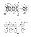
FIG. 5 illustrates another example embodiment of an integrated core 500 for N transformers TX1-TXN, where N is greater than or equal to two (or least five, in the particular example shown in FIG. 5). The transformers TX1-TXN may be employed, for example, in the multiphase power converter 200 of FIG. 2. Each transformer has a core section C1-CN−1 that is shared with an adjacent transformer. In the example of FIG. 5, the transformers TX1-TXN−1 each employ an E core configuration, while the Nth transformer TXN employs an EI core configuration. Each transformer TX1-TXN includes one or more primary windings and one or more secondary windings.
Magnetic flux (illustrated by arrows) flows through each transformer's portion of the integrated core, including its shared core section, when the primary winding(s) of that transformer is energized. Although FIG. 5 illustrates flux flowing through all of the transformers TX1-TXN, it should be appreciated that the primary windings of the transformers TX1-TXN are operated with different phase, which may or may not overlap.
FIG. 6 illustrates an isolated multiphase forward converter 600 employing the transformers TX1-TXN having shared core sections C1-CN−1 of FIG. 5.
FIG. 7A illustrates an example embodiment of an integrated core 700 for a first coupled inductor CIA and a second coupled inductor CIB. The first and second coupled inductors CIA, CIB may be employed, for example, in the subconverters SC1, SC2 illustrated in FIG. 2 and described above.
The first coupled inductor CIA has an EI core configuration and the second coupled inductor CIB has an E core configuration. The EI core configuration of coupled inductor CIA includes a shared yoke 712 (i.e., a shared core section 712), a yoke 704A and three legs 706A, 708A, 710A extending from the yoke 704A to the shared yoke 712. The E core configuration of coupled inductor CIB includes a yoke 704B and three legs 706B, 708B, 710B extending from the yoke 704B to the shared yoke 712. The legs 708A, 708B are positioned between legs 706A, 710A and legs 706B, 710B, respectively. Therefore, the legs 708A, 708B can be referred to as interior legs.
As shown in FIG. 7A, the first coupled inductor CIA includes an input side winding 714A extending about the interior leg 708A of the integrated core 700. Similarly, the second coupled inductor CIB includes an input side winding 714B extending about the interior leg 708B of the integrated core 700. Alternatively, the input side windings 714A, 714B may extend about other portions of the integrated core 700. In the example embodiment shown in FIG. 7A, output side windings for coupled inductors CIA, CIB also extend about the interior legs 708A, 708B, respectively. Further, there are no windings positioned about the shared core section 712.
The integrated core 700 of the coupled inductors CIA, CIB may have the same general configuration as the integrated transformer core 300 shown in FIG. 3A, except the integrated core 700 may include an air gap (not shown) and/or be formed with core material(s) having a higher flux saturation headroom.
FIG. 7A illustrates the flux (indicated by arrows) circulating in the first coupled inductor CIA when its input side winding 714A is energized (i.e. when the coupled inductor CIA is charging), and FIG. 7B illustrates the flux circulating in the first coupled inductor CIA when its input side winding 714A is not energized (i.e., when the coupled inductor CIA is discharging). In both instances, the magnetic flux of the first coupled inductor CIA flows through the interior leg 708A, the legs 706A, 710A and the shared core section 712. Similarly, FIG. 7C illustrates the flux circulating in the second coupled inductor CIB when its input side winding 714B is energized, and FIG. 7D illustrates the flux circulating in the second coupled inductor CIB when its input side winding 714B is not energized. In both instances, the magnetic flux of the second coupled inductor CIB flows through the interior leg 708B, the legs 706B, 710B and the shared core section 712. Accordingly, magnetic flux of each coupled inductor CIA, CIB flows through the shared core section 312.
The input side windings 714A, 714B of the coupled inductors CIA, CIB are preferably energized with nonoverlapping phases (i.e., such that windings 714A and 714B are not both energized at any given time). Further, winding 714B may not be energized while coupled inductor CIA is discharging and, similarly, winding 714A may not be energized while coupled inductor CIB is discharging. Alternatively, winding 714B can be energized while coupled inductor CIA is still discharging and, similarly, winding 714A can be energized while coupled inductor CIB is still discharging. Accordingly, the first coupled inductor CIA and the second coupled inductor CIB may have a 180 degree phase difference. More generally, each coupled inductor may operate at a phase difference equal to 360/n, where n equals the number of coupled inductors. Further, each winding 714A, 714B may be energized by a drive signal having a duty cycle up to fifty percent (50%).
Thus, the shared core section 712 of the adjacent coupled inductors CIA, CIB may be time-shared by the magnetic flux switching at different phases. This may reduce the flux density in the integrated core 700, and thus may reduce iron losses. Therefore, the efficiency of the coupled inductors CIA, CIB may increase.
FIG. 8 illustrates another example embodiment of an integrated core 800 for N coupled inductors CI1-CIN, where N is greater than or equal to two (or least five, in the particular example shown in FIG. 8). The coupled inductors CI1-CIN may be employed, for example, in the multiphase power converter 200 of FIG. 2. Each coupled inductor has a core section CISC1-CISCN−1 that is shared with an adjacent coupled inductor. In the example of FIG. 8, the coupled inductors CI1-CIN each employ an E core configuration, while the Nth coupled inductor CIN employs an EI core configuration. Each coupled inductor CI1-CIN includes one or more input side windings and one or more output side windings.
Magnetic flux (illustrated by arrows) flows through each coupled inductor's portion of the integrated core, including its shared core section, when the input side winding(s) of that coupled inductor is charging and discharging. Although FIG. 8 illustrates flux flowing through all of the coupled inductors CI1-CIN, it should be appreciated that the input side windings of the coupled inductors CI1-CIN are operated with different phase, which may or may not overlap.
FIG. 9 illustrates another example embodiment of an integrated core 900 for a first transformer A and a second transformer B. The first and second transformers A, B may be employed in the subconverters SC1, SC2 illustrated in FIG. 2 and described above. As shown in FIG. 9, the first transformer A has an UI core configuration and the second transformer B has a U core configuration. The UI core configuration includes a shared core section adjacent the U core configuration. Furthermore, as shown in FIG. 9, each transformer A, B includes primary and secondary windings wound about the core.
FIG. 10 illustrates yet another example embodiment of an integrated core 1000 for a first transformer A and a second transformer B. The first and second transformers A, B may be employed in the subconverters SC1, SC2 illustrated in FIG. 2 and described above. As shown in FIG. 10, the first transformer A and the second transformer B include a binocular core configuration having a shared core section. Furthermore, as shown in FIG. 10, each transformer A, B includes primary and secondary windings wound about the core.
FIG. 11 illustrates still another example embodiment of an integrated core 1100 for four transformers A-D. The transformers A-D may be employed in the multiphase power converter 200 of FIG. 2. As shown in FIG. 11, the transformers A-D include a conjoined binocular core configuration having a shared core section between each adjacent transformer. Furthermore, as shown in FIG. 11, each transformer A-D includes primary and secondary windings wound about the core.
Alternatively, coupled inductors may employ the integrated cores 900, 1000, 1100 of FIGS. 9, 10, 11 respectively. Additionally, the coupled inductors including the integrated cores 900, 1000, 1100 may be employed in the multiphase power converter 200 (e.g., subconverters SC1, SC2) of FIG. 2.
Further, various embodiments of the present disclosure may be employed in any suitable switching power supply, signal switching application, etc. without departing from the scope of this disclosure.
The foregoing description of the embodiments has been provided for purposes of illustration and description. It is not intended to be exhaustive or to limit the disclosure. Individual elements or features of a particular embodiment are generally not limited to that particular embodiment, but, where applicable, are interchangeable and can be used in a selected embodiment, even if not specifically shown or described. The same may also be varied in many ways. Such variations are not to be regarded as a departure from the disclosure, and all such modifications are intended to be included within the scope of the disclosure.

Claims (16)

The invention claimed is:
1. A multiphase power converter comprising:
a plurality of subconverters, each subconverter having an input circuit, an output circuit, and a magnetic core coupling the input circuit to the output circuit, the magnetic core of at least one of the plurality of subconverters having a core section that is shared by the magnetic core of another one of the plurality of subconverters; and
a control circuit configured to operate the input circuits of the plurality of subconverters with different phases.
2. The multiphase power converter of claim 1 wherein the magnetic cores of the plurality of subconverters form an integrated core.
3. The multiphase power converter of claim 2 wherein the plurality of subconverters include N converters, and wherein the magnetic cores of the plurality of subconverters include N−1 shared core sections, where N is an integer greater than or equal to two.
4. The multiphase power converter of claim 3 wherein the plurality of magnetic cores include a first magnetic core having an EI core configuration and a second magnetic core having an E core configuration.
5. The multiphase power converter of claim 3 wherein each output circuit includes at least one rectifier.
6. The multiphase power converter of claim 3 wherein each input circuit includes one or more windings extending about its magnetic core.
7. The multiphase power converter of claim 6 wherein the one or more windings of each input circuit extend about an interior leg of its magnetic core.
8. The multiphase power converter of claim 6 wherein there are no windings on the shared core section.
9. The multiphase power converter of claim 3 wherein the output circuits are each coupled to a common terminal.
10. The multiphase power converter of claim 9 further comprising an output terminal coupled to the common terminal.
11. The multiphase power converter of claim 10 further comprising an inductor and/or capacitor coupled between the common terminal and the output terminal.
12. The multiphase power converter of claim 3 wherein the input circuits each employ a forward converter topology.
13. The multiphase power converter of claim 3 wherein each magnetic core is a core of a transformer having a primary side and a secondary side, each input circuit is a primary side circuit and each output circuit is a secondary side circuit.
14. The multiphase power converter of claim 3 wherein each magnetic core is a core of a coupled inductor.
15. The multiphase power converter of claim 3 wherein the different phases are nonoverlapping phases.
16. The multiphase power converter of claim 3 wherein the different phases are overlapping phases.
US13/250,780 2011-09-30 2011-09-30 Multiphase power converters having shared magnetic core sections Active 2034-08-20 US9165707B2 (en)

Priority Applications (4)

Application Number Priority Date Filing Date Title
US13/250,780 US9165707B2 (en) 2011-09-30 2011-09-30 Multiphase power converters having shared magnetic core sections
CN2011205646816U CN202798465U (en) 2011-09-30 2011-12-29 Multi-phase power converter
CN2011104517795A CN103036434A (en) 2011-09-30 2011-12-29 Multiphase power converters having shared magnetic core sections
CN201810789868.2A CN108964463A (en) 2011-09-30 2011-12-29 Multiphase power converter with shared core portion

Applications Claiming Priority (1)

Application Number Priority Date Filing Date Title
US13/250,780 US9165707B2 (en) 2011-09-30 2011-09-30 Multiphase power converters having shared magnetic core sections

Publications (2)

Publication Number Publication Date
US20130083575A1 US20130083575A1 (en) 2013-04-04
US9165707B2 true US9165707B2 (en) 2015-10-20

Family

ID=47825636

Family Applications (1)

Application Number Title Priority Date Filing Date
US13/250,780 Active 2034-08-20 US9165707B2 (en) 2011-09-30 2011-09-30 Multiphase power converters having shared magnetic core sections

Country Status (2)

Country Link
US (1) US9165707B2 (en)
CN (3) CN108964463A (en)

Cited By (3)

* Cited by examiner, † Cited by third party
Publication number Priority date Publication date Assignee Title
US10985647B2 (en) 2015-12-01 2021-04-20 Astee International Limited Multiphase interleaved forward power converters including clamping circuits
US11711020B2 (en) 2020-04-06 2023-07-25 Astec International Limited Transformers for multiphase power converters
US11749433B2 (en) 2019-03-05 2023-09-05 Astec International Limited Transformers having integrated magnetic structures for power converters

Families Citing this family (10)

* Cited by examiner, † Cited by third party
Publication number Priority date Publication date Assignee Title
WO2012008889A1 (en) * 2010-07-15 2012-01-19 Saab Ab A multiphase transformer rectifier unit
US9165707B2 (en) * 2011-09-30 2015-10-20 Astec International Limited Multiphase power converters having shared magnetic core sections
ITUB20152190A1 (en) 2015-07-15 2017-01-15 St Microelectronics Srl ELECTRONIC CONVERTER, AND ITS PROJECT PROCEDURE FOR A MAGNETIC COMPONENT
CN106953526A (en) * 2016-01-07 2017-07-14 中兴通讯股份有限公司 A kind of direct current multiple input single output controlled resonant converter and its control method
CN106998142B (en) * 2016-01-25 2019-08-30 台达电子企业管理(上海)有限公司 Controlled resonant converter, the inductance of multi-channel parallel integrate magnetic element and transformer integrates magnetic element
US10395819B2 (en) * 2016-08-30 2019-08-27 Astec International Limited Multiple phase power converters having integrated magnetic cores for transformer and inductor windings
DE102017104138A1 (en) * 2017-02-28 2018-08-30 Christian-Albrechts-Universität Zu Kiel Voltage transformer, method of operation and computer program
CN108809079B (en) 2017-05-05 2019-11-05 台达电子企业管理(上海)有限公司 Power inverter, inductance element and inductance cut off control method
US11430598B2 (en) 2017-10-12 2022-08-30 Mitsubishi Electric Corporation Power converter
CN108242323A (en) * 2017-12-22 2018-07-03 浙江东睦科达磁电有限公司 A kind of E-type magnetic powder core

Citations (10)

* Cited by examiner, † Cited by third party
Publication number Priority date Publication date Assignee Title
US4045722A (en) * 1975-04-28 1977-08-30 Hitachi, Ltd. Power converter system
US4366532A (en) * 1981-05-11 1982-12-28 Westinghouse Electric Corp. AC/DC or DC/AC Converter system with improved AC-line harmonic reduction
US4488136A (en) 1981-05-18 1984-12-11 Westinghouse Electric Corp. Combination transformer with common core portions
US4513361A (en) * 1983-02-15 1985-04-23 Hughes Aircraft Company Multi-phase DC-to-AC and DC-to-DC boost converter
US4631471A (en) * 1985-03-25 1986-12-23 At&T Bell Laboratories Inductor apparatus for application of ferroresonant regulators
US4779181A (en) * 1986-08-18 1988-10-18 Almond Instruments Company, Inc. Multiphase low harmonic distortion transformer
US6362986B1 (en) 2001-03-22 2002-03-26 Volterra, Inc. Voltage converter with coupled inductive windings, and associated methods
US6420953B1 (en) 2000-05-19 2002-07-16 Pulse Engineering. Inc. Multi-layer, multi-functioning printed circuit board
US7352269B2 (en) 2002-12-13 2008-04-01 Volterra Semiconductor Corporation Method for making magnetic components with N-phase coupling, and related inductor structures
US7598839B1 (en) 2004-08-12 2009-10-06 Pulse Engineering, Inc. Stacked inductive device and methods of manufacturing

Family Cites Families (7)

* Cited by examiner, † Cited by third party
Publication number Priority date Publication date Assignee Title
JPH01227410A (en) * 1988-03-08 1989-09-11 Kijima:Kk Small-sized transformer
US7138789B2 (en) * 2004-01-21 2006-11-21 Intersil Corporation Multiphase converter with zero voltage switching
US9647555B2 (en) * 2005-04-08 2017-05-09 Lincoln Global, Inc. Chopper output stage for arc welder power source
GB2445526A (en) * 2005-10-14 2008-07-09 Astec Int Ltd Multiphase DC to DC converter
CN1929279B (en) * 2006-08-16 2010-05-12 南京航空航天大学 Magnetism-integrated double decompression semi-bridge converter
CN201369231Y (en) * 2008-11-28 2009-12-23 东莞创慈磁性元件有限公司 Improvement structure of two-in-one transformer
US9165707B2 (en) * 2011-09-30 2015-10-20 Astec International Limited Multiphase power converters having shared magnetic core sections

Patent Citations (10)

* Cited by examiner, † Cited by third party
Publication number Priority date Publication date Assignee Title
US4045722A (en) * 1975-04-28 1977-08-30 Hitachi, Ltd. Power converter system
US4366532A (en) * 1981-05-11 1982-12-28 Westinghouse Electric Corp. AC/DC or DC/AC Converter system with improved AC-line harmonic reduction
US4488136A (en) 1981-05-18 1984-12-11 Westinghouse Electric Corp. Combination transformer with common core portions
US4513361A (en) * 1983-02-15 1985-04-23 Hughes Aircraft Company Multi-phase DC-to-AC and DC-to-DC boost converter
US4631471A (en) * 1985-03-25 1986-12-23 At&T Bell Laboratories Inductor apparatus for application of ferroresonant regulators
US4779181A (en) * 1986-08-18 1988-10-18 Almond Instruments Company, Inc. Multiphase low harmonic distortion transformer
US6420953B1 (en) 2000-05-19 2002-07-16 Pulse Engineering. Inc. Multi-layer, multi-functioning printed circuit board
US6362986B1 (en) 2001-03-22 2002-03-26 Volterra, Inc. Voltage converter with coupled inductive windings, and associated methods
US7352269B2 (en) 2002-12-13 2008-04-01 Volterra Semiconductor Corporation Method for making magnetic components with N-phase coupling, and related inductor structures
US7598839B1 (en) 2004-08-12 2009-10-06 Pulse Engineering, Inc. Stacked inductive device and methods of manufacturing

Non-Patent Citations (1)

* Cited by examiner, † Cited by third party
Title
Sen, et al., A High Efficient Integrated Planar Transformer for Primary-Parallel Isolated Boost Converters, 2010, pp. 4605-4610.

Cited By (5)

* Cited by examiner, † Cited by third party
Publication number Priority date Publication date Assignee Title
US10985647B2 (en) 2015-12-01 2021-04-20 Astee International Limited Multiphase interleaved forward power converters including clamping circuits
US11296595B2 (en) 2015-12-01 2022-04-05 Astec International Limited Multiphase interleaved forward power converters including clamping circuits
US11664721B2 (en) 2015-12-01 2023-05-30 Astec International Limited Multiphase interleaved forward power converters including clamping circuits
US11749433B2 (en) 2019-03-05 2023-09-05 Astec International Limited Transformers having integrated magnetic structures for power converters
US11711020B2 (en) 2020-04-06 2023-07-25 Astec International Limited Transformers for multiphase power converters

Also Published As

Publication number Publication date
CN103036434A (en) 2013-04-10
CN202798465U (en) 2013-03-13
US20130083575A1 (en) 2013-04-04
CN108964463A (en) 2018-12-07

Similar Documents

Publication Publication Date Title
US9165707B2 (en) Multiphase power converters having shared magnetic core sections
US10742123B1 (en) Low common mode noise transformers and switch-mode DC-DC power converters
US7183754B2 (en) DC/DC converter
US10395819B2 (en) Multiple phase power converters having integrated magnetic cores for transformer and inductor windings
US9019061B2 (en) Magnetic device formed with U-shaped core pieces and power converter employing the same
US20100067263A1 (en) Dual interleaved flyback converter for high input voltage
US11469674B2 (en) Resonant DC-DC converter
JP2009005579A (en) Power conversion circuit
CN111492568B (en) Interleaved LLC Resonant Converter
US7138787B2 (en) DC/DC converter
JP5830915B2 (en) Power conversion circuit
CN210039873U (en) Transformer and multiphase interleaved power converter
JPWO2018116437A1 (en) Power converter
WO2018116438A1 (en) Power conversion device
JP4175367B2 (en) Switching power supply
EP2441161B1 (en) Dual drive system for transformer isolated half bridge and full bridge forward converters
US20220224224A1 (en) Multiphase interleaved forward power converters including clamping circuits
US20150070942A1 (en) Dc-dc converter
JP2006166550A (en) Input/output isolation type dc-dc converter
KR20220017392A (en) polyphase switching regulator
US20150016150A1 (en) Multi-phase converter
JP2006165465A (en) Winding component
JP2017195726A (en) DC-DC converter
JP2004007907A (en) Switching power unit
JP2019079946A (en) Coil component, circuit board, and power supply device

Legal Events

Date Code Title Description
AS Assignment

Owner name: ASTEC INTERNATIONAL LIMITED, HONG KONG

Free format text: ASSIGNMENT OF ASSIGNORS INTEREST;ASSIGNORS:KIPPLEY, ROBERT H.;SCHUMACHER, BRADLEY J.;STIEDL, ANDREAS;AND OTHERS;SIGNING DATES FROM 20110929 TO 20111006;REEL/FRAME:027335/0251

STCF Information on status: patent grant

Free format text: PATENTED CASE

MAFP Maintenance fee payment

Free format text: PAYMENT OF MAINTENANCE FEE, 4TH YEAR, LARGE ENTITY (ORIGINAL EVENT CODE: M1551); ENTITY STATUS OF PATENT OWNER: LARGE ENTITY

Year of fee payment: 4

MAFP Maintenance fee payment

Free format text: PAYMENT OF MAINTENANCE FEE, 8TH YEAR, LARGE ENTITY (ORIGINAL EVENT CODE: M1552); ENTITY STATUS OF PATENT OWNER: LARGE ENTITY

Year of fee payment: 8