US9163829B2 - Moving bed heat exchanger for circulating fluidized bed boiler - Google Patents
Moving bed heat exchanger for circulating fluidized bed boiler Download PDFInfo
- Publication number
- US9163829B2 US9163829B2 US11/954,855 US95485507A US9163829B2 US 9163829 B2 US9163829 B2 US 9163829B2 US 95485507 A US95485507 A US 95485507A US 9163829 B2 US9163829 B2 US 9163829B2
- Authority
- US
- United States
- Prior art keywords
- ash particles
- hot ash
- vessel
- collected
- air
- Prior art date
- Legal status (The legal status is an assumption and is not a legal conclusion. Google has not performed a legal analysis and makes no representation as to the accuracy of the status listed.)
- Active, expires
Links
Images


Classifications
-
- F—MECHANICAL ENGINEERING; LIGHTING; HEATING; WEAPONS; BLASTING
- F23—COMBUSTION APPARATUS; COMBUSTION PROCESSES
- F23C—METHODS OR APPARATUS FOR COMBUSTION USING FLUID FUEL OR SOLID FUEL SUSPENDED IN A CARRIER GAS OR AIR
- F23C10/00—Fluidised bed combustion apparatus
- F23C10/02—Fluidised bed combustion apparatus with means specially adapted for achieving or promoting a circulating movement of particles within the bed or for a recirculation of particles entrained from the bed
- F23C10/04—Fluidised bed combustion apparatus with means specially adapted for achieving or promoting a circulating movement of particles within the bed or for a recirculation of particles entrained from the bed the particles being circulated to a section, e.g. a heat-exchange section or a return duct, at least partially shielded from the combustion zone, before being reintroduced into the combustion zone
- F23C10/08—Fluidised bed combustion apparatus with means specially adapted for achieving or promoting a circulating movement of particles within the bed or for a recirculation of particles entrained from the bed the particles being circulated to a section, e.g. a heat-exchange section or a return duct, at least partially shielded from the combustion zone, before being reintroduced into the combustion zone characterised by the arrangement of separation apparatus, e.g. cyclones, for separating particles from the flue gases
- F23C10/10—Fluidised bed combustion apparatus with means specially adapted for achieving or promoting a circulating movement of particles within the bed or for a recirculation of particles entrained from the bed the particles being circulated to a section, e.g. a heat-exchange section or a return duct, at least partially shielded from the combustion zone, before being reintroduced into the combustion zone characterised by the arrangement of separation apparatus, e.g. cyclones, for separating particles from the flue gases the separation apparatus being located outside the combustion chamber
-
- F—MECHANICAL ENGINEERING; LIGHTING; HEATING; WEAPONS; BLASTING
- F23—COMBUSTION APPARATUS; COMBUSTION PROCESSES
- F23C—METHODS OR APPARATUS FOR COMBUSTION USING FLUID FUEL OR SOLID FUEL SUSPENDED IN A CARRIER GAS OR AIR
- F23C10/00—Fluidised bed combustion apparatus
- F23C10/005—Fluidised bed combustion apparatus comprising two or more beds
-
- F—MECHANICAL ENGINEERING; LIGHTING; HEATING; WEAPONS; BLASTING
- F23—COMBUSTION APPARATUS; COMBUSTION PROCESSES
- F23C—METHODS OR APPARATUS FOR COMBUSTION USING FLUID FUEL OR SOLID FUEL SUSPENDED IN A CARRIER GAS OR AIR
- F23C10/00—Fluidised bed combustion apparatus
- F23C10/18—Details; Accessories
- F23C10/28—Control devices specially adapted for fluidised bed, combustion apparatus
- F23C10/30—Control devices specially adapted for fluidised bed, combustion apparatus for controlling the level of the bed or the amount of material in the bed
- F23C10/32—Control devices specially adapted for fluidised bed, combustion apparatus for controlling the level of the bed or the amount of material in the bed by controlling the rate of recirculation of particles separated from the flue gases
-
- F—MECHANICAL ENGINEERING; LIGHTING; HEATING; WEAPONS; BLASTING
- F28—HEAT EXCHANGE IN GENERAL
- F28D—HEAT-EXCHANGE APPARATUS, NOT PROVIDED FOR IN ANOTHER SUBCLASS, IN WHICH THE HEAT-EXCHANGE MEDIA DO NOT COME INTO DIRECT CONTACT
- F28D13/00—Heat-exchange apparatus using a fluidised bed
-
- F—MECHANICAL ENGINEERING; LIGHTING; HEATING; WEAPONS; BLASTING
- F28—HEAT EXCHANGE IN GENERAL
- F28D—HEAT-EXCHANGE APPARATUS, NOT PROVIDED FOR IN ANOTHER SUBCLASS, IN WHICH THE HEAT-EXCHANGE MEDIA DO NOT COME INTO DIRECT CONTACT
- F28D7/00—Heat-exchange apparatus having stationary tubular conduit assemblies for both heat-exchange media, the media being in contact with different sides of a conduit wall
-
- F—MECHANICAL ENGINEERING; LIGHTING; HEATING; WEAPONS; BLASTING
- F23—COMBUSTION APPARATUS; COMBUSTION PROCESSES
- F23C—METHODS OR APPARATUS FOR COMBUSTION USING FLUID FUEL OR SOLID FUEL SUSPENDED IN A CARRIER GAS OR AIR
- F23C2206/00—Fluidised bed combustion
- F23C2206/10—Circulating fluidised bed
- F23C2206/103—Cooling recirculating particles
-
- F—MECHANICAL ENGINEERING; LIGHTING; HEATING; WEAPONS; BLASTING
- F28—HEAT EXCHANGE IN GENERAL
- F28D—HEAT-EXCHANGE APPARATUS, NOT PROVIDED FOR IN ANOTHER SUBCLASS, IN WHICH THE HEAT-EXCHANGE MEDIA DO NOT COME INTO DIRECT CONTACT
- F28D21/00—Heat-exchange apparatus not covered by any of the groups F28D1/00 - F28D20/00
- F28D2021/0019—Other heat exchangers for particular applications; Heat exchange systems not otherwise provided for
- F28D2021/0045—Other heat exchangers for particular applications; Heat exchange systems not otherwise provided for for granular materials
Definitions
- the present invention relates generally to fluidized bed type fossil fuel fired heat generating systems, and more particularly to the re-circulating of heated solids in a fluidized bed type fossil fuel fired heat generating system.
- Heat generating systems with furnaces for combusting fossil fuels have long been employed to generate controlled heat, with the objective of doing useful work.
- the work might be in the form of direct work, as with kilns, or might be in the form of indirect work, as with steam generators for industrial or marine applications or for driving turbines that produce electric power.
- Modern water-tube furnaces for steam generation can be of various types including fluidized-bed boilers. While there are various types of fluidized-bed boilers, all operate on the principle that a gas is injected to fluidize solids prior to combustion in the reaction chamber.
- CFB fluidized-bed
- the bed then becomes fluidized, with the gas cushion between the solids allowing the particles to move freely and giving the bed a liquid-like characteristic.
- the bulk density of the bed is relatively high at the bottom and decreases, as it flows upward through the reaction chamber where fuel is combusted to generate heat.
- the solid particles forming the bed of the circulating fluidized bed boiler typically include fuel particles, such as crushed coal or other solid fuel, and sorbent particles, such as crushed limestone, dolomite or other alkaline earth material. Combustion of the fuel in the reaction chamber of the boiler produces flue gas and ash. During the combustion process, the sulfur in the fuel is oxidized to form sulfur dioxide (SO 2 ), which is mixed with the other gasses in the furnace to form the flue gas.
- SO 2 sulfur dioxide
- the ash consists primarily of unburned fuel, inert material in the fuel, and sorbent particles, and is sometimes referred to as bed materials or re-circulated solids.
- the ash is carried entrained in the flue gas in an upwardly flow and is exhausted from the furnace with the hot flue gas. While entrained therein and being transported by the flue gas, the sorbent particles that are present within the reaction chamber, i.e., furnace or combustor, capture, i.e., absorb, sulfur from the SO 2 in the flue gas. This reduces the amount of SO 2 in the flue gas that ultimately reaches the stack and as such the amount of SO 2 that is exhausted into the environment.
- the reaction chamber i.e., furnace or combustor
- fresh fuel and sorbent particles as well as recycled ash are continuously introduced to the bed of the circulating fluidized bed boiler.
- the flue gas and ash are directed to a separator, such as a cyclone, to remove the ash from the flue gas.
- a separator such as a cyclone
- Two parallel paths are then typically provided for re-circulating the separated ash back to the bed of the circulating fluidized bed boiler.
- the separated ash may be directed along either or both of said parallel paths by a solids flow control valve located between the separator and said two parallel paths.
- Such solid flow control valves are well known in the art and may be controlled pneumatically, hydraulically or in some other functionally equivalent manner.
- Circulating fluidized bed boilers are designed so as to operate within a narrow temperature range in order to thereby promote the combustion of fuel, the calcination of limestone and the absorption of sulfur.
- This narrow range of furnace temperatures must be maintained over a range of furnace loads, from full load down to some level of partial loading.
- the furnace temperature is controlled through absorption of heat from the flue gas and bed ash that is produced as a result of combustion in the reactor chamber of the furnace. While most of the heat absorption is through the furnace walls and the in-furnace panels, on larger circulating fluidized bed boilers, heat absorption by the furnace enclosure walls and in-furnace panels is insufficient to achieve the desired operating temperatures.
- external heat exchangers are employed to absorb heat from the ash that is removed from the flue gas in the cyclone or other separator, before the ash is re-circulated to the to the circulating fluidized bed boiler.
- Such external heat exchangers are commonly referred to as External Heat Exchangers (EXE) or Fluid Bed Heat Exchangers (FBHEs).
- the sorbent and other ash particles are fluidized and these fluidized ash particles are then transported to and are made to flow through a FBHE by means of injected high pressure gas, e.g., air, which is normally at a pressure of about 200 inches water gage (WG).
- a working fluid such as water, steam, a mixture of both or some other coolant flowing through a tube bundle within the FBHE.
- the flow of cooled fluidized particles is then reintroduced into the furnace.
- the amount of cooling of the fluidized particles that is performed in the FBHE is typically controlled based on the gas temperature within the furnace that is desired.
- the sorbent and other ash particles are also fluidized and are entrained therewithin and are transported by an injected high pressure gas, such as air, again normally at a pressure of around 200 inches WG.
- the fluidized particles are directed through an ash re-circulation pipe having a seal, commonly referred to as a seal pot or siphon seal, that is suitably installed so as to be operative to ensure proper flow of gas and ash in the primary loop, which is defined as the furnace, the separator, i.e., cyclone, seal pot and FBHE.
- the seal pot functions to prevent a backflow of gas and solid particles from the furnace into the re-circulation pipe. From the seal pot, the sorbent and other solid ash particles are then reintroduced into the furnace without being cooled.
- Q Btu/hr
- R Btu/hr ⁇ Ft2 ⁇ F
- S Square Feet
- LTMD Deg. F.
- R constant transfer rate
- the moving bed heat exchanger (MBHE) constructed in accordance with the present invention improves on the LMTD over that in typical FBHEs by permitting full counter-flow of solids and working fluid.
- a moving bed heat exchanger (MBHE) is provided.
- the MBHE could, for example, be installed in the primary recirculation loop of a circulating fluidized bed boiler with said MBHE having a vessel, a plurality of tubes, and a plurality of air inlets.
- the vessel of the MBHE includes an upper portion with a feed opening, a lower portion with a floor having a discharge opening, and an intermediate portion disposed between said upper portion and said lower portion.
- the vessel of the MBHE receives hot ash particles, such as hot limestone particles with absorbed sulfur, via the feed opening thereof. These hot ash particles are typically received from a cyclone or other type separator after these hot ash particles have been removed from the flue gas that is exhausted from a furnace, such as the furnace of a circulating fluidized bed boiler.
- the vessel of the MBHE is suitably configured, i.e., is sized, shaped and/or has structural components, so as to be operative to direct a gravity flow of the hot ash particles, which are received thereby, from the upper portion of the vessel through the intermediate portion of the vessel to the floor of the lower portion of the vessel, and so as to be operative as well to collect the ash particles on the floor of the lower portion of the vessel.
- This directed gravity flow of the ash particles may be referred to as a “moving bed”.
- the plurality of tubes of the MBHE which preferably are in the form of finned tubes, are disposed in the intermediate portion of the vessel of the MBHE and are configured so as to be operative to direct a flow of working fluid, such as water, steam, a mixture of water and steam, or some other fluid, in a direction substantially orthogonal to the direction of the directed gravity flow of the aforereferenced hot ash particles through the intermediate portion of the vessel. If the direction of the gravity flow of the aforereferenced hot ash particles is vertically downward, the flow in a direction substantially orthogonal to the direction of such gravity flow of the aforereferenced hot ash particles would be a substantially horizontal flow.
- the flow of the working fluid is such that heat from the hot ash particles is transferred to the working fluid to thereby cool said hot ash particles as the latter are directed to the lower portion of the vessel of the MBHE.
- the plurality of air inlets of the MBHE which will typically be in the form of air nozzles, are suitably configured so as to be operative to inject air into the lower portion of the vessel of the MBHE in order to thereby control the amount of the previously hot ash particles, which have now been cooled, that are collected and discharged through the discharge opening of the vessel of the MBHE.
- the amount of heat that is transferred from the hot ash particles to the working fluid will normally correspond to the amount of the previously hot ash particles, which have now been cooled, that are collected and discharged through the discharge opening of the vessel of the MBHE.
- the amount of such cooled ash particles, which are collected and discharged is controlled based on either the temperature of the gas in the furnace or the temperature of the working fluid leaving the MBHE.
- the air that is injected fluidizes the now cooled ash particles, which have been collected, and transports these now fluidized cooled ash particles through the discharge opening of the MBHE.
- a discharge pipe suitably configured so as to be operative to direct the transported now fluidized cooled ash particles through the discharge opening of the MBHE may be provided.
- such a discharge pipe will have an inlet disposed within the lower portion of the vessel of the MBHE at a distance that is located above the floor of said lower portion of the vessel of the MBHE. Said inlet could, for example, be located 12 inches above the floor of the lower portion of the vessel of the MBHE, although this may vary depending on the implementation without departing from the essence of the present invention. If such a discharge pipe is provided, the now fluidized cooled ash particles are accordingly transported into the inlet of said discharge pipe and from there through the discharge opening of the vessel of the MBHE.
- a hood is preferably disposed within the lower portion of the vessel of the MBHE at a distance that is located above the inlet of the aforereferenced discharge pipe.
- This hood is suitably configured so as to be operative to support the weight of the ash that is above the hood and so as to as well direct the transported ash particles that are below the hood into the inlet of the aforereferenced discharge pipe.
- the above described upper, intermediate and lower portions of the vessel of the MBHE form a first compartment of the vessel of the MBHE, and said vessel also includes a second compartment that includes another separate feed opening and another floor having another separate discharge opening.
- Said vessel receives other ash particles, which are also hot, via the other feed opening thereof.
- Said vessel is also further configured so as to be operative to direct a gravity flow of the hot other ash particles received thereby to the floor of the second compartment thereof and so as to be operative as well to collect said hot other ash particles on this other floor thereof.
- a plurality of other air inlets preferably is also provided.
- Said plurality of other air inlets which will typically also be in the form of air nozzles, are suitably configured so as to be operative to inject air into the second compartment of the vessel of the MBHE in order to thereby control the amount of the hot other ash particles, which are collected and discharged through the other discharge opening of the vessel of the MBHE.
- both cooled particles from one compartment and hot particles from the other compartment can be discharged, e.g., for recycling to the furnace of a circulating fluidized bed boiler.
- the amount of hot other ash particles, which are collected and discharged through the other discharge opening of the vessel of the MBHE is controlled such that the amount of the hot other ash particles collected on the floor of the second compartment of the vessel of the MBHE is sufficient to seal the second compartment of the vessel of the MBHE against a flow of an external gas through the discharge opening of the vessel of the MHE into the second compartment of the vessel of the MBHE.
- the present invention can be implemented to provide a MBHE and a seal pot unit, which are integrated.
- FIG. 1 depicts a simplified elevational view of the primary loop of a circulating fluidized bed boiler consisting of a furnace and an integrated unit that includes a moving bed heat exchanger (MBHE) and a seal pot, constructed in accordance with the present invention.
- MBHE moving bed heat exchanger
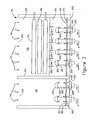
- FIG. 2 is an elevational view presenting a more detailed depiction of the integrated unit of a MBHE and a seal pot that is illustrated in FIG. 1 , constructed in accordance with the present invention.
- FIG. 3 is a plan view depicting a preferred arrangement of the air plenums and discharge pipes that are illustrated in FIG. 2 , constructed in accordance with the present invention.
- FIG. 4 shows an enlarged and more detailed depiction of components used to control the discharge of ash from the integrated unit of a MBHE and a seal pot that are illustrated in FIG. 2 , constructed in accordance with the present invention.
- FIG. 5 is a plan view showing an exemplary arrangement of the orifices of the air nozzles that are illustrated in FIG. 4 , constructed in accordance with the present invention.
- FIG. 6 shows an enlarged and more detailed depiction of a first alternative form of components used to control the discharge of ash from the integrated unit of a MBHE and a seal pot that are illustrated in FIG. 2 , constructed in accordance with the present invention.
- FIG. 7 shows an enlarged and more detailed description of a second alternative from of components used to control the discharge of ash from the integrated unit of a MBHE and a seal pot that are illustrated in FIG. 2 , constructed in accordance with the present invention.
- FIG. 1 of the drawings there is illustrated a circulating fluidized bed boiler 100 embodying a circulating fluidized bed 110 .
- fresh fuel typically crushed coal
- fresh sorbent commonly crushed limestone
- recycled hot ash is also transported from a seal pot 165 to the circulating fluidized bed 110 via a conveying line 170 .
- recycled cool ash is also transported from a moving bed heat exchanger (MBHE) 155 to the furnace, i.e., reaction chamber, of the circulating fluidized bed boiler 100 via a conveying line 160 .
- MBHE moving bed heat exchanger
- a plenum 160 supplies air to the fresh fuel, fresh sorbent and recycled ash particles that are fed to the furnace of the circulating fluidized bed boiler 100 in order to thereby fluidize these particles of fresh fuel, fresh sorbent and recycled ash so as to thereby create therefrom the circulating fluidized bed 110 in a manner well-known to those skilled in this art.
- the flue gas and ash generated in the furnace of the circulating fluidized bed boiler 100 are exhausted from the furnace of the circulating fluidized bed boiler 100 via a conveying line 125 .
- the flue gas serves as a carrier and transports the ash entrained therewith from the furnace of the circulating fluidized bed boiler 100 .
- a cyclone 130 is employed to separate from the flue gas the ash that is entrained therewith. From the cyclone 130 , the flue gas, which is now substantially free of the ash previously entrained therewith, is transported via a conveying line 135 preferably to any downstream processing equipment, e.g., heat exchangers, air pollution control (APC) equipment, and thereafter ultimately to an exhaust stack.
- any downstream processing equipment e.g., heat exchangers, air pollution control (APC) equipment
- the ash after being separated from the flue gas in the cyclone 130 is directed from the cyclone 130 to a moving bed heat exchanger (MBHE) 155 via a first path 140 and then to a seal pot 165 via a second path 145 .
- a moving bed heat exchanger MBHE
- the seal pot 165 are housed in an integrated unit denoted in the drawings by the reference numeral 150 .
- FIG. 2 there is illustrated the details of the MBHE and the seal pot integrated unit 150 .
- hot ash particles 140 from the cyclone separator 130 are fed into the MBHE 155 in a distributed manner. That is, preferably, the hot ash particles that enter the MBHE 155 are distributed across the width and depth of the MBHE 155 .
- the hot ash particles 145 are also fed in a distributed manner to the seal pot 165 .
- the hot ash particles 140 move through the MBHE 155 and the hot ash particles 145 move through the seal pot 165 each by means of a gravity flow. This gravity flow of the ash particles 140 and 145 may be referred to as a “moving bed”.
- the MBHE 155 has three primary portions; namely, an upper portion 200 , an intermediate portion 205 and a lower portion 210 .
- the moving bed of ash particles 140 enters the upper portion 200 of the MBHE 155 through what may be referred to as a feed opening 202 , which is depicted at the top of the MBHE 155 in FIG. 2 .
- This opening 202 can be suitably configured in any number of ways without departing from the essence of the present invention, as will be well understood by those skilled in this art.
- the MBHE 155 is suitably sized, shaped and/or has structural components (not shown in the interest of maintaining clarity of illustration in the drawings) so as to be operative to direct the moving bed of hot ash particles 140 from the upper portion 200 thereof to the immediate portion 205 thereof of the MBHE 155 .
- the intermediate portion 205 includes a heat exchanger 215 typically consisting of boiler pressure parts. These pressure parts preferably include a bundle of finned tubes (not shown in the interest of maintaining clarity of illustration in the drawings) through which a working fluid, generally in the form of steam and/or of water, flows. This working fluid serves as a coolant, and is used to recover heat from the moving bed of hot ash particles 140 as the hot ash particles 140 are made to flow through the heat exchanger 215 .
- the bundle of finned tubes of the heat exchanger 215 are preferably oriented such that the flow of the working fluid therethrough is substantially orthogonal to the gravity flow of the moving bed of hot ash particles through the heat exchanger 215 .
- the fins beneficially extend from the tubes in a direction that is substantially parallel to the direction of flow of the moving bed of hot ash particles.
- air plenums 235 are disposed below the floor 272 of the MBHE 155 in order to thereby provide a flow of low pressure air 240 , e.g., at a pressure of 65 inches WG, into the lower portion 210 of the MBHE 155 through air inlets in the floor 272 of the MBHE 155 . Further details regarding the flow of the low pressure air 240 into the lower portion 210 of the MBHE 155 will be discussed hereinbelow. Injection of the low pressure air 240 is operative to cause the collected cooled ash particles 252 to be transported through a discharge opening 220 in the floor 272 of the MBHE 155 .
- a discharge pipe 225 extends from a position above the floor surface 275 through each of the floor discharge openings 220 .
- a hood 230 is provided above the inlet opening 227 (as best understood with reference to FIG. 4 ) of each respective one of the discharge pipes 225 . If such a discharge pipe 225 and hood 230 is utilized for purposes of effecting the discharge of the collected cooled ash particles 252 therewith, collected cooled ash particles 252 are transported by the low pressure air 240 to a position located above an inlet opening of each respective one of the discharge pipes 225 .
- the collected cooled ash particles that are being transported are identified in FIG. 4 by the reference numeral 255 .
- Each hood 230 is operative to deflect the transported collected cooled ash particles 255 into the inlet 227 of, and through, a respective one of the discharge pipes 225 .
- the transported collected cooled ash particles 255 leaving the discharge pipe 225 are re-circulated to the furnace of the circulating fluidized bed boiler 100 via conveying line 160 .
- a common wall 270 separates the MBHE 155 from the seal pot 165 .
- the hot ash particles 145 enter the seal pot 165 through a feed opening 204 as is illustrated in FIG. 2 .
- the hot ash particles 145 are subjected to a gravity flow in the seal pot 165 , that is, from the feed opening 204 of the seal pot 165 to the surface 280 of the floor 282 of the seal pot 165 .
- a layer of collected hot ash particles 260 forms on the surface 280 of the floor 282 of the seal pot 165 .
- the seal pot 165 also includes air plenums denoted by the reference numeral 235 ′ that are designed to be operative for injecting air to transport the collected hot ash particles 260 through the discharge openings 220 ′ in the floor 280 of the seal pot 165 .
- the hot ash particles that are being so transported are identified in FIG. 2 by the reference numeral 265 .
- a hooded discharge pipe 225 ′ is preferably mounted through each of the discharge openings 220 ′ in order to thereby form the passageways through which the hot ash particles 265 are capable of being discharged from the seal pot 165 .
- the hot ash particles 265 that are discharged from the seal pot discharge openings 220 ′ are designed to be re-circulated back to the circulating fluidized bed boiler 100 via a conveying line 170 .
- the amount of collected cooled ash particles 252 that are discharged through the discharge openings 220 in the MBHE 155 can be controlled.
- the amount of the collected hot ash particles 260 that are discharged through the discharge openings 220 ′ can also be controlled.
- the amount of low pressure air 240 to the MBHE 155 the amount of heat transferred from the hot ash particles 140 to the working fluid flowing in the heat exchanger 215 can also be controlled.
- the amount of heat transferred from the hot ash particles 140 to the working fluid will correspond to the amount of collected cooled ash particles 250 that are discharged through the discharge openings 220 .
- This control is preferably effected based on the temperature of the gas in the furnace of the circulating fluidized bed boiler 100 or the steam/water temperature in the MBHE 155 , but could equally well be based on other furnace related parameters without departing from the essence of the present invention.
- the integrated MBHE and seal pot unit 150 can be used to control the combustion temperature in the furnace of the circulating fluidized bed boiler 100 . Since the ash moves through the MBHE 155 and across the heat exchanger 215 in a gravity flow, the injection of high pressure air in order to thereby transport the ash and induce the heat transfer is not required. Thus, there is no requirement in accordance with the present invention for employing any high pressure fluidizing blowers. As a result, this significantly reduces not only material cost but also power consumption.
- the counter current flow of the moving bed of ash vertically downward in the MBHE 155 results in higher log mean temperature difference (LMTD), which contributes to higher heat transfer rates in the MBHE 155 and thus reduced heat exchanger surface requirements.
- LMTD log mean temperature difference
- the MBHE 155 is capable of utilizing a plurality of finned tubes that embody a high fin density without hindering the flow of ash therethrough, the heat transfer surface can be arranged in a very compact design.
- FBHEs fluidized bed heat exchangers
- FIG. 3 is a plan view, by way of exemplification, of a preferred arrangement of the air plenum, and pipe and hood discharges in accordance with the present invention, which are sometimes referred to as low pressure ash control valves (LPACVs).
- LPACVs low pressure ash control valves
- the LPACVs are distributed throughout the floor area of both the MBHE 155 and the seal pot 165 .
- each row A-F of LPACVs is controlled by air, which is injected via an individual plenum 235 or 235 ′.
- the air which is supplied to the individual plenums 235 or 235 ′, may be controlled individually.
- the number of rows of LPACVs in the seal pot 165 and the MBHE 155 may, without departing from the essence of the present invention, vary depending on the particular application in which the LPACVs are being employed. Furthermore, the number of discharge openings in each row may, without departing from the essence of the present invention, also vary depending on the particular application in which the LPACVs are being employed. Higher air flow rates from the plenums 235 in the MBHE 155 are operative to promote increased ash flow rates across the heat exchanger 215 , and hence lower aggregate temperatures of the ash that is returned to the furnace of the circulating fluidized bed boiler 100 from the MBHE 155 .
- the air which is injected into the MBHE 155 and the seal pot 165 , is controlled in order to thereby cause a specific level, i.e., quantity, of ash to be maintained in the MBHE 155 and the seal pot 165 so as to thus provide the required furnace to cyclone seal.
- the injection of air into the MBHE 155 is also controlled in order to thereby control the flow of ash across the heat exchanger 215 so as to thus achieve a specific steam generator parameter, such as, for example, a specific gas or steam temperature within the furnace of the circulating fluidized bed boiler 100 .
- the injection of air into the MBHE 155 and the seal pot 165 is also controlled in order to thereby maintain an even distribution of the cooled and hot ash particles in the ash return lines 160 and 170 to the furnace of the circulating fluidized bed boiler 100 .
- the arranging of the discharge openings in rows and the regulating of the air, which is injected for purposes of effecting the transport of the ash through each row of the discharge openings 220 or 220 ′ an even ash flow can be thereby ensured across the width of the MBHE 155 and of the seal pot 165 and in each of the return lines 160 and 170 as well.
- the regulation of the ash discharge from the rows A-F is further operative to promote even coolant temperatures within the tubes of the heat exchanger 215 .
- the MBHE 155 and seal pot 165 are capable of being controlled independently of each other without departing from the essence of the present invention, if such is desired, the MBHE 155 is capable of being operated with the seal pot 165 shut down or visa versa.
- the seal pot 165 and MBHE 155 being arranged in parallel relation to each other, large particles, which are discharged from the cyclone 130 can without departing from the essence of the present invention, if such is desired, be channeled away from the MBHE 155 for purposes of being discharged out through the seal pot 165 .
- FIGS. 4 and 5 of the drawings there is further illustrated a LPACV 475 for controlling the flow of ash through the discharge openings 220 and 220 ′ in the MBHE 155 and the seal pot 165 .
- the LPACV 475 includes the discharge pipe 225 or 225 ′ and the associated hood 230 or 230 ′ that have been previously described hereinbefore.
- the discharge pipe 225 or 225 ′ extends through the discharge opening 220 or 220 ′ in the floor 272 or 282 of the MBHE 155 or the seal pot 165 .
- each of the MBHE 155 and the seal pot 165 includes a steel casing 420 or 420 ′, respectively, on which a layer of refractory material 425 or 425 ′, respectively, is preferably provided in accordance with the present invention.
- the discharge opening 220 or 220 ′ is formed so as to extend through both the refractory material 425 or 425 ′ and the steel casing 420 or 420 ′.
- the discharge pipe 225 or 225 ′ in accordance with the present invention extends approximately 12 inches above the floor surface 275 or 280 , although the height of the discharge pipe 225 or 225 ′ may vary without departing from the essence of the present invention depending on the nature of the particular application in question.
- the hood 230 or 230 ′ is preferably supported off the discharge pipe 225 or 225 ′ itself and in addition preferably also extends to a height of between 18 and 24 inches above the floor 272 or 282 .
- this height range may also in addition vary without departing from the essence of the present invention.
- the bottom of the hood 230 or 230 ′ preferably but not necessarily extends below the inlet opening 227 in the case of MBHE 155 and below the inlet opening 227 ′ in the case of the seal pot 165 .
- Air denoted in the drawings by the reference numeral 475 from a suitable source thereof is fed via a duct 405 to the plenum 235 or 235 ′ which is operative to distribute such air, which in turn effects the feed thereof to a manifold 412 , in the case of the MBHE 155 , or to the manifold 412 ′, in the case of the seal pot 165 .
- FIG. 5 of the drawings there is depicted one of numerous arrangements of the air nozzles 415 or 415 ′ that could be utilized without departing from the essence of the present invention for purposes of effecting the injection of the low pressure air 240 or 240 ′ into the MBHE 155 or the seal pot 165 .
- Arranging the low pressure air nozzles 415 or 415 ′ so as to thereby function in the required manner is well understood by those skilled in this art, and accordingly it should be understood that the arrangement of the nozzles that is illustrated in FIG. 5 is by way of exemplification and not limitation, and that any number of other nozzle arrangements could equally well be utilized without departing from the essence of the present invention.
- a small amount of low pressure air 240 or 240 ′ is injected to control the solids within the MBHE 155 and the seal pot 165 .
- the pressure of the injected air is much lower than the surrounding pressure of the solids.
- the pressure of the solids on the floor of the compartment that defines the MBHE 155 and on the floor of the compartment that defines the seal pot 165 corresponds to the height of the solids in the respective one of the aforementioned compartments. In most cases, the pressure of the solids in such compartments will be well in excess of 200 inches WG. However, the pressure of the air 240 or 240 ′ injected into the respective compartment need only be a low pressure. Such low pressure air can be provided for this purpose from a primary or secondary air source that is commonly available at circulating fluidized bed boiler plants. For example, such primary air, which is generally so available at a pressure of 65 inches WG, can be utilized as the source of the air 475 .
- the short height of the discharge pipe 225 or 225 ′ above the floor surface 275 or 280 effectively enables the height of the bed of collected ash 252 or 260 to be reduced concomitantly, and hence the amount of pressure that is required in order to effect the transport of the solids to the discharge pipe inlet 227 or 227 ′.
- the injected air 240 or 240 ′ is designed to effectively bubble up through the collected ash 252 and 260 and is then deflected by the hood 230 or 230 ′ into the discharge pipe inlet 227 or 227 ′, and through the discharge pipe 225 or 225 ′ into the conveying line 160 or 170 .
- the low pressure air effects the transport of the ash from the MBHE 155 and/or seal pot 165 to the furnace of the circulating fluidized bed boiler 100 .
- the bed of ash moves in a downwardly direction thereby promoting a heat transfer therefrom to the working fluid flowing through the tubes of the heat exchanger 215 .
- FIGS. 6 and 7 of the drawings there is illustrated an alternative LPACV design 500 that can be employed in the MBHE 155 without departing from the essence of the present invention. Moreover, this alternative LPACV design 500 can be installed in the floor 272 or below the floor 272 of the MBHE 155 . To this end, in this alternative LPACV design 500 there is utilized the same hydrodynamic principles as the LPACV that is illustrated in FIG. 4 of the drawings. The LPACV design 500 that is illustrated in FIGS. 6 and 7 of the drawings differs from the LPACV design that is illustrated in FIG.
- a labyrinth chamber 520 is utilized for purposes of forming the hood 510 whereby the lower pressure condition P 2 that is achieved versus the higher pressure condition P 1 is formed by the static head of the material of the circulating fluidized bed material 110 .
- the controller 450 is capable of controlling the variable air flow valve 410 in order to thereby effect a pulsation of air through the nozzles 415 or 415 ′ in an on-off sequence.
- the controller 450 also is capable of controlling the variable air flow valve 410 such that the injectors 415 or 415 ′ inject a continuous stream of low pressure air at varying flow rates into the respective compartment.
- a non-mechanical control of ash flow across the MBHE 155 and the seal pot 165 is provided utilizing air at a pressure far lower than the surrounding pressure of the ash collected on the respective compartment floor. Because only low pressure air is required, the power usage of the circulating fluidized bed boiler plant can thereby be reduced, and hence the circulating fluidized bed boiler plant can operate at a higher energy efficiency, e.g., a higher plant heat rate. Furthermore, the amount of ash being discharged from the MBHE 155 and the seal pot 165 can be effectively controlled to the desired extent over the full load range of the circulating fluidized bed boiler 100 .
- FBHEs and seal pots which are of conventional construction
- This technique to which the present invention is directed beneficially eliminates the need for the relatively high pressure fluidizing air that is required by FBHEs and seal pots, which are of conventional construction, and can reduce not only the expense of the high pressure blowers and fluidizing nozzles that are commonly required therefor, but also the dynamic loading to which the structural steel, which is required for purposes of supporting FBHEs and seal pots that embody a conventional construction, is subjected.
- the consumption of power conventionally required to operate such blowers in order for them to thereby provide the supply of high pressure air is also eliminated.
- this technique to which the present invention is directed beneficially facilitates higher heat transfer rates in the heat exchanger than those now possible using conventionally constructed FBHEs because of the relatively low log mean temperature difference LMTD of the fluidized ash flow within such conventionally constructed FBHEs.
Abstract
Description
Claims (16)
Priority Applications (7)
| Application Number | Priority Date | Filing Date | Title |
|---|---|---|---|
| US11/954,855 US9163829B2 (en) | 2007-12-12 | 2007-12-12 | Moving bed heat exchanger for circulating fluidized bed boiler |
| PL08859596T PL2217856T3 (en) | 2007-12-12 | 2008-11-24 | Moving bed heat exchanger for circulating fluidized bed boiler |
| EP08859596.2A EP2217856B8 (en) | 2007-12-12 | 2008-11-24 | Moving bed heat exchanger for circulating fluidized bed boiler |
| CN200880121028.3A CN101896770B (en) | 2007-12-12 | 2008-11-24 | Moving bed heat exchanger for circulating fluidized bed boiler |
| ES08859596.2T ES2606224T3 (en) | 2007-12-12 | 2008-11-24 | Mobile bed heat exchanger for circulating fluidized bed boiler |
| PCT/US2008/084473 WO2009076046A1 (en) | 2007-12-12 | 2008-11-24 | Moving bed heat exchanger for circulating fluidized bed boiler |
| TW097148332A TWI370889B (en) | 2007-12-12 | 2008-12-11 | Moving bed heat exchanger for circulating fluidized bed boiler |
Applications Claiming Priority (1)
| Application Number | Priority Date | Filing Date | Title |
|---|---|---|---|
| US11/954,855 US9163829B2 (en) | 2007-12-12 | 2007-12-12 | Moving bed heat exchanger for circulating fluidized bed boiler |
Publications (2)
| Publication Number | Publication Date |
|---|---|
| US20090151902A1 US20090151902A1 (en) | 2009-06-18 |
| US9163829B2 true US9163829B2 (en) | 2015-10-20 |
Family
ID=40350155
Family Applications (1)
| Application Number | Title | Priority Date | Filing Date |
|---|---|---|---|
| US11/954,855 Active 2032-10-07 US9163829B2 (en) | 2007-12-12 | 2007-12-12 | Moving bed heat exchanger for circulating fluidized bed boiler |
Country Status (7)
| Country | Link |
|---|---|
| US (1) | US9163829B2 (en) |
| EP (1) | EP2217856B8 (en) |
| CN (1) | CN101896770B (en) |
| ES (1) | ES2606224T3 (en) |
| PL (1) | PL2217856T3 (en) |
| TW (1) | TWI370889B (en) |
| WO (1) | WO2009076046A1 (en) |
Families Citing this family (8)
| Publication number | Priority date | Publication date | Assignee | Title |
|---|---|---|---|---|
| US9617087B2 (en) * | 2010-10-28 | 2017-04-11 | General Electric Technology Gmbh | Control valve and control valve system for controlling solids flow, methods of manufacture thereof and articles comprising the same |
| US9557115B2 (en) * | 2010-10-28 | 2017-01-31 | General Electric Technology Gmbh | Orifice plate for controlling solids flow, methods of use thereof and articles comprising the same |
| US8800498B2 (en) * | 2010-12-30 | 2014-08-12 | Kellogg Brown & Root Llc | Systems and methods for exchanging heat in a gasification system |
| CN102519528B (en) * | 2011-12-29 | 2014-02-26 | 中国科学院过程工程研究所 | Solid flow measurement method and system of recirculating fluidized bed |
| ES2555034T3 (en) * | 2013-02-01 | 2015-12-28 | Consejo Superior De Investigaciones Científicas (Csic) | System and procedure for energy storage using circulating fluidized bed combustors |
| US9458838B2 (en) * | 2014-07-17 | 2016-10-04 | The Babcock & Wilcox Company | Power generation plant integrating concentrated solar power receiver and pressurized heat exchanger |
| CN111442262B (en) * | 2020-03-30 | 2021-12-17 | 神华神东电力有限责任公司 | Slag removal adjusting system and method |
| CN111964043B (en) * | 2020-09-01 | 2023-04-07 | 福建省圣新环保股份有限公司 | Novel chicken manure boiler return bed and monitoring method thereof |
Citations (28)
| Publication number | Priority date | Publication date | Assignee | Title |
|---|---|---|---|---|
| US3957419A (en) * | 1973-12-17 | 1976-05-18 | Babcock & Wilcox Limited | Fluidised bed combustion system |
| US4009121A (en) * | 1975-08-26 | 1977-02-22 | Exxon Research And Engineering Company | Method of temperature control in catalyst regeneration |
| US4039290A (en) * | 1972-05-15 | 1977-08-02 | Kureha Kagaku Kogyo Kabushiki Kaisha | Spent activated carbon regenerator |
| US4552203A (en) | 1982-04-28 | 1985-11-12 | Creusot-Loire | Method and device for controlling the temperature of a reaction carried out in a fluidized bed |
| US4614167A (en) * | 1984-11-16 | 1986-09-30 | Asea Stal Ab | Combustion chamber having beds located one above the other and a method of controlling it |
| US4637455A (en) * | 1984-09-28 | 1987-01-20 | Combustion Engineering, Inc. | Support rack for tubes immersed in a fluidized bed |
| US4684375A (en) | 1984-04-20 | 1987-08-04 | Framatome & Cie. | Method for gasifying a material using a circulating fluidized bed |
| US4709663A (en) | 1986-12-09 | 1987-12-01 | Riley Stoker Corporation | Flow control device for solid particulate material |
| US4813479A (en) | 1986-12-11 | 1989-03-21 | Gotaverken Energy Ab | Adjustable particle cooler for a circulating fluidized bed reactor |
| US4934282A (en) | 1988-02-18 | 1990-06-19 | Ishikawajima-Harima Jukogyo Kabushiki Kaisha | Circulating type fluidized bed combustion apparatus |
| US5060599A (en) | 1986-06-12 | 1991-10-29 | Gotaverken Energy Aktiebolag | Method and reactor for combustion in a fluidized bed |
| WO1994011672A1 (en) | 1992-11-10 | 1994-05-26 | A. Ahlstrom Corporation | Method and apparatus for recovering heat in a fluidized bed reactor |
| US5425412A (en) | 1992-11-10 | 1995-06-20 | A. Alhstrom Corporation | Method and apparatus for operating a circulating fluidized bed reactor system |
| US5570645A (en) | 1995-02-06 | 1996-11-05 | Foster Wheeler Energy Corporation | Fluidized bed system and method of operating same utilizing an external heat exchanger |
| US5634516A (en) | 1993-06-23 | 1997-06-03 | Foster Wheeler Energia Oy | Method and apparatus for treating or utilizing a hot gas flow |
| US5840258A (en) | 1992-11-10 | 1998-11-24 | Foster Wheeler Energia Oy | Method and apparatus for transporting solid particles from one chamber to another chamber |
| WO1999015829A1 (en) | 1997-09-22 | 1999-04-01 | Combustion Engineering, Inc. | Fluid bed ash cooler |
| WO1999032217A1 (en) | 1997-12-19 | 1999-07-01 | Foster Wheeler Energia Oy | Method and apparatus for controlling heat transfer from solid particles in a fluidized bed |
| WO2000020818A1 (en) | 1998-10-02 | 2000-04-13 | Foster Wheeler Energia Oy | Method and apparatus in a fluidized bed heat exchanger |
| JP2000161628A (en) | 1998-11-27 | 2000-06-16 | Hitachi Zosen Corp | Circulation type fluidized bed reaction apparatus |
| WO2001035020A1 (en) | 1999-11-10 | 2001-05-17 | Foster Wheeler Energia Oy | Circulating fluidized bed reactor |
| US20030015150A1 (en) | 2001-07-17 | 2003-01-23 | Felix Belin | CFB with controllable in-bed heat exchanger |
| US6554061B2 (en) * | 2000-12-18 | 2003-04-29 | Alstom (Switzerland) Ltd | Recuperative and conductive heat transfer system |
| JP2004132621A (en) | 2002-10-11 | 2004-04-30 | Mitsui Eng & Shipbuild Co Ltd | Particle circulation rate controlling method and device for circulating fluidized bed boiler |
| US6779492B2 (en) | 2001-10-30 | 2004-08-24 | Alstom (Switzerland) Ltd. | Circulating fluidized bed reactor device |
| WO2004091768A1 (en) | 2003-04-15 | 2004-10-28 | Foster Wheeler Energia Oy | A method of and an apparatus for recovering heat in a fluidized bed reactor |
| US6938780B2 (en) | 2001-10-30 | 2005-09-06 | Alstom (Switzerland) Ltd. | Centrifugal separator in particular for fluidized bed reactor device |
| EP1612479A2 (en) | 2004-07-01 | 2006-01-04 | Kvaerner Power Oy | Circulating fluidized bed boiler |
Family Cites Families (2)
| Publication number | Priority date | Publication date | Assignee | Title |
|---|---|---|---|---|
| TW571049B (en) * | 2001-11-12 | 2004-01-11 | Ishikawajima Harima Heavy Ind | Circulating fluidized bed boiler |
| CN1304783C (en) * | 2001-12-22 | 2007-03-14 | 浙江大学 | Wind control type material outside circulating device of circulating fluid bed boiler |
-
2007
- 2007-12-12 US US11/954,855 patent/US9163829B2/en active Active
-
2008
- 2008-11-24 WO PCT/US2008/084473 patent/WO2009076046A1/en active Application Filing
- 2008-11-24 ES ES08859596.2T patent/ES2606224T3/en active Active
- 2008-11-24 CN CN200880121028.3A patent/CN101896770B/en not_active Expired - Fee Related
- 2008-11-24 EP EP08859596.2A patent/EP2217856B8/en not_active Not-in-force
- 2008-11-24 PL PL08859596T patent/PL2217856T3/en unknown
- 2008-12-11 TW TW097148332A patent/TWI370889B/en not_active IP Right Cessation
Patent Citations (29)
| Publication number | Priority date | Publication date | Assignee | Title |
|---|---|---|---|---|
| US4039290A (en) * | 1972-05-15 | 1977-08-02 | Kureha Kagaku Kogyo Kabushiki Kaisha | Spent activated carbon regenerator |
| US3957419A (en) * | 1973-12-17 | 1976-05-18 | Babcock & Wilcox Limited | Fluidised bed combustion system |
| US4009121A (en) * | 1975-08-26 | 1977-02-22 | Exxon Research And Engineering Company | Method of temperature control in catalyst regeneration |
| US4552203A (en) | 1982-04-28 | 1985-11-12 | Creusot-Loire | Method and device for controlling the temperature of a reaction carried out in a fluidized bed |
| US4684375A (en) | 1984-04-20 | 1987-08-04 | Framatome & Cie. | Method for gasifying a material using a circulating fluidized bed |
| US4637455A (en) * | 1984-09-28 | 1987-01-20 | Combustion Engineering, Inc. | Support rack for tubes immersed in a fluidized bed |
| US4614167A (en) * | 1984-11-16 | 1986-09-30 | Asea Stal Ab | Combustion chamber having beds located one above the other and a method of controlling it |
| US5060599A (en) | 1986-06-12 | 1991-10-29 | Gotaverken Energy Aktiebolag | Method and reactor for combustion in a fluidized bed |
| US4709663A (en) | 1986-12-09 | 1987-12-01 | Riley Stoker Corporation | Flow control device for solid particulate material |
| US4813479A (en) | 1986-12-11 | 1989-03-21 | Gotaverken Energy Ab | Adjustable particle cooler for a circulating fluidized bed reactor |
| US4934282A (en) | 1988-02-18 | 1990-06-19 | Ishikawajima-Harima Jukogyo Kabushiki Kaisha | Circulating type fluidized bed combustion apparatus |
| WO1994011672A1 (en) | 1992-11-10 | 1994-05-26 | A. Ahlstrom Corporation | Method and apparatus for recovering heat in a fluidized bed reactor |
| US5406914A (en) | 1992-11-10 | 1995-04-18 | A. Ahlstrom Corporation | Method and apparatus for operating a circulating fluidized bed reactor system |
| US5425412A (en) | 1992-11-10 | 1995-06-20 | A. Alhstrom Corporation | Method and apparatus for operating a circulating fluidized bed reactor system |
| US5840258A (en) | 1992-11-10 | 1998-11-24 | Foster Wheeler Energia Oy | Method and apparatus for transporting solid particles from one chamber to another chamber |
| US5634516A (en) | 1993-06-23 | 1997-06-03 | Foster Wheeler Energia Oy | Method and apparatus for treating or utilizing a hot gas flow |
| US5570645A (en) | 1995-02-06 | 1996-11-05 | Foster Wheeler Energy Corporation | Fluidized bed system and method of operating same utilizing an external heat exchanger |
| WO1999015829A1 (en) | 1997-09-22 | 1999-04-01 | Combustion Engineering, Inc. | Fluid bed ash cooler |
| WO1999032217A1 (en) | 1997-12-19 | 1999-07-01 | Foster Wheeler Energia Oy | Method and apparatus for controlling heat transfer from solid particles in a fluidized bed |
| WO2000020818A1 (en) | 1998-10-02 | 2000-04-13 | Foster Wheeler Energia Oy | Method and apparatus in a fluidized bed heat exchanger |
| JP2000161628A (en) | 1998-11-27 | 2000-06-16 | Hitachi Zosen Corp | Circulation type fluidized bed reaction apparatus |
| WO2001035020A1 (en) | 1999-11-10 | 2001-05-17 | Foster Wheeler Energia Oy | Circulating fluidized bed reactor |
| US6554061B2 (en) * | 2000-12-18 | 2003-04-29 | Alstom (Switzerland) Ltd | Recuperative and conductive heat transfer system |
| US20030015150A1 (en) | 2001-07-17 | 2003-01-23 | Felix Belin | CFB with controllable in-bed heat exchanger |
| US6779492B2 (en) | 2001-10-30 | 2004-08-24 | Alstom (Switzerland) Ltd. | Circulating fluidized bed reactor device |
| US6938780B2 (en) | 2001-10-30 | 2005-09-06 | Alstom (Switzerland) Ltd. | Centrifugal separator in particular for fluidized bed reactor device |
| JP2004132621A (en) | 2002-10-11 | 2004-04-30 | Mitsui Eng & Shipbuild Co Ltd | Particle circulation rate controlling method and device for circulating fluidized bed boiler |
| WO2004091768A1 (en) | 2003-04-15 | 2004-10-28 | Foster Wheeler Energia Oy | A method of and an apparatus for recovering heat in a fluidized bed reactor |
| EP1612479A2 (en) | 2004-07-01 | 2006-01-04 | Kvaerner Power Oy | Circulating fluidized bed boiler |
Non-Patent Citations (2)
| Title |
|---|
| International Search Report for PCT/US2008/084473; Mailing Date Mar. 25, 2009. |
| Written Opinion of the International Searching Authority, PCT/US2008/084473, International Filing Date Nov. 24, 2008. |
Also Published As
| Publication number | Publication date |
|---|---|
| ES2606224T3 (en) | 2017-03-23 |
| TW200938772A (en) | 2009-09-16 |
| WO2009076046A1 (en) | 2009-06-18 |
| TWI370889B (en) | 2012-08-21 |
| EP2217856B8 (en) | 2016-12-21 |
| EP2217856A1 (en) | 2010-08-18 |
| CN101896770B (en) | 2014-08-20 |
| EP2217856B1 (en) | 2016-09-07 |
| PL2217856T3 (en) | 2017-02-28 |
| CN101896770A (en) | 2010-11-24 |
| US20090151902A1 (en) | 2009-06-18 |
Similar Documents
| Publication | Publication Date | Title |
|---|---|---|
| US9163829B2 (en) | Moving bed heat exchanger for circulating fluidized bed boiler | |
| KR100828108B1 (en) | CFB with controllable in-bed heat exchanger | |
| RU2393386C1 (en) | Heat exchanger with fluidised bed for boiler with circulating fluidised bed, and boiler with circulating fluidised bed, which is equipped with heat exchanger with fluidised bed | |
| KR101485477B1 (en) | Circulating fluidized bed boiler having two external heat exchanger for hot solids flow | |
| KR100306026B1 (en) | Method and apparatus for driving a circulating fluidized bed system | |
| SE457013B (en) | FLUIDIZED BODY COMBUSTION SYSTEM | |
| CA2740254C (en) | A circulating fluidized bed boiler | |
| JPH0518005B2 (en) | ||
| AU2008282617B2 (en) | Integral waterwall external heat exchangers | |
| KR101898077B1 (en) | Circulating fluidized bed boiler | |
| US5954000A (en) | Fluid bed ash cooler | |
| RU2537482C2 (en) | Circulating fluidised bed with secondary air supply nozzles to furnace chamber | |
| US4454838A (en) | Steam generator having a circulating fluidized bed and a dense pack heat exchanger for cooling the recirculated solid materials | |
| EP0571234B1 (en) | Process for decreasing N2O emissions from a fluidized bed reactor | |
| CA3141409C (en) | Spray, jet, and/or splash induced circulation among integrated bubbling zones in a bubbling fluidized bed reactor | |
| RU2698173C1 (en) | Forced fluidized bed boiler | |
| US20050056195A1 (en) | Method and apparatus for improving combustion in recovery boilers | |
| JP5748784B2 (en) | Fluidized bed reactor equipment | |
| JP2939338B2 (en) | Fluidized bed reactor and method for producing the same | |
| JPH05346203A (en) | Fluidized bed combustion apparatus equipping stationarily fluidizezd bed and method for producing high temperature water or vapor using same | |
| FI126744B (en) | Arrangement and method of fluidization boiler | |
| KR101816326B1 (en) | Apparatus for Discharging Bottom Ash and Circulating Fluidized Bed Boiler having the same | |
| Nie et al. | The Characters of DONGFANG® 300MW CFBB | |
| Shatil et al. | Controlling the furnace process in coal-fired boilers | |
| SUBRAMANIAM | OPERATIONAL STUDY OF CIRCULATING FLUIDIZED BED STEAM GENERATOR |
Legal Events
| Date | Code | Title | Description |
|---|---|---|---|
| AS | Assignment |
Owner name: ALSTOM TECHNOLOGY LTD, SWITZERLAND Free format text: ASSIGNMENT OF ASSIGNORS INTEREST;ASSIGNORS:JACOBS, ROBERT V;JUKKOLA, GLEN D;MYLCHREEST, GEORGE D;AND OTHERS;REEL/FRAME:020533/0808;SIGNING DATES FROM 20080115 TO 20080123 Owner name: ALSTOM TECHNOLOGY LTD, SWITZERLAND Free format text: ASSIGNMENT OF ASSIGNORS INTEREST;ASSIGNORS:JACOBS, ROBERT V;JUKKOLA, GLEN D;MYLCHREEST, GEORGE D;AND OTHERS;SIGNING DATES FROM 20080115 TO 20080123;REEL/FRAME:020533/0808 |
|
| FEPP | Fee payment procedure |
Free format text: PAYOR NUMBER ASSIGNED (ORIGINAL EVENT CODE: ASPN); ENTITY STATUS OF PATENT OWNER: LARGE ENTITY |
|
| STCF | Information on status: patent grant |
Free format text: PATENTED CASE |
|
| AS | Assignment |
Owner name: GENERAL ELECTRIC TECHNOLOGY GMBH, SWITZERLAND Free format text: CHANGE OF NAME;ASSIGNOR:ALSTOM TECHNOLOGY LTD;REEL/FRAME:039714/0578 Effective date: 20151102 |
|
| MAFP | Maintenance fee payment |
Free format text: PAYMENT OF MAINTENANCE FEE, 4TH YEAR, LARGE ENTITY (ORIGINAL EVENT CODE: M1551); ENTITY STATUS OF PATENT OWNER: LARGE ENTITY Year of fee payment: 4 |
|
| MAFP | Maintenance fee payment |
Free format text: PAYMENT OF MAINTENANCE FEE, 8TH YEAR, LARGE ENTITY (ORIGINAL EVENT CODE: M1552); ENTITY STATUS OF PATENT OWNER: LARGE ENTITY Year of fee payment: 8 |