US9162467B2 - Ink cartridge for inkjet printers - Google Patents
Ink cartridge for inkjet printers Download PDFInfo
- Publication number
- US9162467B2 US9162467B2 US13/997,346 US201113997346A US9162467B2 US 9162467 B2 US9162467 B2 US 9162467B2 US 201113997346 A US201113997346 A US 201113997346A US 9162467 B2 US9162467 B2 US 9162467B2
- Authority
- US
- United States
- Prior art keywords
- ink cartridge
- ink
- outer housing
- cartridge according
- recess
- Prior art date
- Legal status (The legal status is an assumption and is not a legal conclusion. Google has not performed a legal analysis and makes no representation as to the accuracy of the status listed.)
- Expired - Fee Related, expires
Links
Images


Classifications
-
- B—PERFORMING OPERATIONS; TRANSPORTING
- B41—PRINTING; LINING MACHINES; TYPEWRITERS; STAMPS
- B41J—TYPEWRITERS; SELECTIVE PRINTING MECHANISMS, i.e. MECHANISMS PRINTING OTHERWISE THAN FROM A FORME; CORRECTION OF TYPOGRAPHICAL ERRORS
- B41J2/00—Typewriters or selective printing mechanisms characterised by the printing or marking process for which they are designed
- B41J2/005—Typewriters or selective printing mechanisms characterised by the printing or marking process for which they are designed characterised by bringing liquid or particles selectively into contact with a printing material
- B41J2/01—Ink jet
- B41J2/17—Ink jet characterised by ink handling
- B41J2/175—Ink supply systems ; Circuit parts therefor
- B41J2/17503—Ink cartridges
- B41J2/1752—Mounting within the printer
- B41J2/17523—Ink connection
-
- B—PERFORMING OPERATIONS; TRANSPORTING
- B41—PRINTING; LINING MACHINES; TYPEWRITERS; STAMPS
- B41J—TYPEWRITERS; SELECTIVE PRINTING MECHANISMS, i.e. MECHANISMS PRINTING OTHERWISE THAN FROM A FORME; CORRECTION OF TYPOGRAPHICAL ERRORS
- B41J2/00—Typewriters or selective printing mechanisms characterised by the printing or marking process for which they are designed
- B41J2/005—Typewriters or selective printing mechanisms characterised by the printing or marking process for which they are designed characterised by bringing liquid or particles selectively into contact with a printing material
- B41J2/01—Ink jet
- B41J2/17—Ink jet characterised by ink handling
- B41J2/175—Ink supply systems ; Circuit parts therefor
- B41J2/17503—Ink cartridges
- B41J2/17553—Outer structure
Definitions
- the invention relates to an ink cartridge for inkjet printers, having an outer housing and an ink container located inside, in particular an ink bag, which comprises an ink outlet piece through which the ink container can be contacted from the outside in a fluid-conductive manner.
- an ink cartridge for the self-aligning insertion in a printer comprises an outer housing, which in practice is produced from plastic, in which an ink bag is provided, the flexible outer walls of which are formed by aluminium or nylon film.
- the ink bag can be contacted in a fluid-conductive manner from the printer through an ink outlet piece by way of interface means or puncturing means belonging to the printer.
- a puncturing needle of the interface means of the printer punctures the ink outlet piece when the ink cartridge is inserted in the printer.
- guide openings are provided, which serve for receiving guide extensions on the printer side.
- These guide openings interact with the extensions on the printer side such that when the cartridge is inserted in the printer, the cartridge first contacts the extensions on the printer side and is brought in position through these. Following this, the puncturing needle punctures the ink outlet piece in a defined position.
- the guiding function of the guide openings is ensured through the extensions on the printer side abutting the inner circumference of the guide openings or through the resultant backpressure. This is achieved in that the diameter of the extensions on the printer approximately corresponds to the diameter of the guide openings.
- a support plate is provided on the ink bag which serves to stiffen the ink bag on a bag side.
- a filling level indicator is provided, which as soon as the ink bag is (almost) empty of ink, protrudes through a recess in the outer housing.
- the filling level indicator can exert pressure on a switch (attached outside the ink cartridge) in the printer, as a result of which on the printer side a low ink filling level in the cartridge can be detected.
- a similar ink cartridge is described in DE 692 14 512 T2 (EP 016 088 B1).
- the ink cartridge described there is characterized in that the ink outlet piece is designed circular in cross section and in that in the ink outlet piece a circular groove is formed, which is positively connected to the outer housing such that the ink outlet piece is held and positioned in a predetermined position relative to the housing.
- a semi-circular notch is provided for receiving the groove of the ink outlet piece.
- an ink cartridge in which the support plate comprises portions projecting away in a co-planar manner, through which the support plate supports itself on the outer housing. On emptying the ink cartridge, the portions projecting away in a co-planar manner rub along the inside of the outer housing.
- plastic cartridges of the prior art can only be disposed in an environmentally friendly manner with much effort.
- plastic requires mineral oil, a raw material which is becoming increasingly valuable.
- a so-called “bulk ink system” in which an ink reservoir arranged outside the printer supplies an ink cartridge (provided in addition to the ink reservoir) arranged in the printer by means of an ink feed line.
- the guiding means-free housing of the ink reservoir in this case can be of cardboard or plastic. In contrast with the commercially available plastic ink cartridge, no centring of the freely positionable ink reservoir is necessary.
- a further such “bulk ink system” is also known, wherein the guiding means-free housing of the freely positionable ink reservoir is of cardboard.
- the ink cartridge which is connected to the ink reservoir via an ink line is a moulding, usually of a half plastic, which is adapted to the shape of the cartridge receiving region of the printer.
- a printing frame in particular for the printing of T-shirts is known, in which a multiplicity of freely positionable and guiding means-free ink reservoirs are placed onto a frame.
- the ink reservoirs are connected to the printing head via flexible hoses, which are to ensure that they can be freely positioned.
- ink reservoirs which are connected by way of locally flexible hoses, to also produce the outer housing from a cellulose material such as cardboard or pasteboard.
- ink cartridges comprise guiding means in order to align or to centre the ink cartridge relative to the fixed-location puncturing or interface means in the printer when being pushed in.
- the interface means can comprise counter-guiding means, wherein these guide the ink cartridge into a desired position through a counter-force on the guiding means when the ink cartridge is inserted.
- the invention is based on the object of improving an ink cartridge for the direct insertion in an inkjet printer so that it is ecologically more compatible and can in the long term be produced economically at stable prices.
- the ink cartridge of the present invention makes possible, compared with the prior art, a particularly environmentally friendly design which is safe for the future. This is achieved in that cellulose material is used as main material for the outer housing, in particular, at least four, preferably six lateral surfaces of the outer housing consist of cellulose material. Because of this, an environmentally compatible production and an environmentally friendly disposal become possible.
- Cellulose material i.e. the chemical digestion of plant fibres, is produced from naturally renewable raw materials, can be favourably recycled and consists itself mostly of recycled material.
- both the position of the cartridge relative to the interface puncturing means in the utilisable state as well as the position movement during the insertion has to be within a defined framework so that the ink cartridge is aligned or centred and a puncturing needle for example punctures the ink outlet piece of the ink cartridge and not next to the latter in an undefined manner.
- mouldings which are unitarily formed with the housing are used with popular plastic ink cartridges from the prior art.
- the ink cartridge in principle is not suitable for use with interface means or self-aligning insertion since the shaping necessary for centring cannot be easily achieved.
- a paper and/or cardboard material is/are not sufficiently stable or hard for the guiding function. It is therefore provided according to the invention that guiding means, in particular a guide arm, are provided on the outer shell of the ink cartridge, so that the ink cartridge aligns itself relative to the ink port when being inserted in the printer.
- These guiding means are preferably of a material (or material mixture or material combination), which has a greater stability than the material of the outer shell, wherein as greater stability a greater stiffness (preferably measured through the modulus of elasticity and/or the shear modulus), a greater strength (in particular compressive strength) and/or a greater hardness (preferably measured according to Shore, Mohs, Martens, Brinell and/or Rockwell) of the material has to be considered, in particular, the material comprises or consists of plastic, metal and/or wood. These materials have the stability necessary for the alignment, so that in particular in the case of an insertion in the printer which is offset with respect to the desired position, the active forces can be favourably absorbed without any plastic deformation occurring.
- the guiding means comprise a guide arm which laterally protrudes from a longitudinal side wall of the cartridge.
- This guide arm is designed so that it can guide the ink cartridge in the printer by means of a guide, in particular a guide rail which longitudinally extends in a desired insertion direction.
- a guide in particular a guide rail which longitudinally extends in a desired insertion direction.
- it is preferentially of a material, a material alloy and/or a multi-layer construction, e.g. laminate, in particular with a support layer, comprising or consisting of plastic, metal and/or wood.
- the guide arm is designed as an angular element, wherein a leg projects through a recess of the longitudinal side wall of the ink cartridge, which can then be contacted by the printer on its part located outside the outer housing.
- a leg of the angle is fixed on an inner wall of the ink cartridge, preferentially glued to the latter.
- configuring the guide arms as a T-shaped angle as a result of which the guide arm can be fixed on a further surface of the outer housing.
- the guide arm is to be preferably provided on the lower part and fixed there.
- a recess for the guide pin is to be preferably provided in this case.
- this recess does not have to be adapted to the guide arm in an accurately fitting manner but it can be clearly wider than said guide arm and in particular extend as far as to the bottom of the ink cartridge.
- the guiding means can comprise an axial extension and/or a depression of a suitable material, in particular plastic, metal and/or wood.
- the outer housing should be at least for the greatest part be of cellulose material, i.e. the area component of cellulose material on the inner and outer surfaces of the outer housing should be at least 80 percent, preferably at least 95 percent.
- the outer housing is formed by pasteboard or cardboard, wherein pasteboard describes a material substantially of cellulose material with a grammage below 600 g/m 2 and cardboard is a material substantially comprising cellulose material with a grammage of over 600 g/m 2 .
- One or multi-ply corrugated board has proved to be particularly suitable as material for the outer housing.
- the type of corrugation of the corrugated board is preferably a micro-corrugation having a corrugation pitch between 3.0 mm and 3.5 mm and a corrugation height between 1.0 mm and 1.8 mm. These values offer a sound compromise of stability and space requirement.
- the ink cartridge is constructed in a cuboid manner and comprises side walls, more specifically a front wall, a back wall, two longitudinal side walls as well as a bottom and a lid, wherein the longitudinal extension of the ink cartridge is designed larger than the width extension and the width extension is designed larger than the height extension.
- the longitudinal extension of the ink cartridge preferably is between 40 cm and 60 cm, in particular between 45 cm and 55 cm, its width extension is preferably between 9 cm and 11 cm and its height extension is preferably between 2 cm and 3 cm.
- the ink cartridge comprises an upper part and a lower part which are designed so that they can be inserted into each other and together form the outer housing of the ink cartridge.
- the upper part comprises the lid and side wall layers.
- the lower part comprises the bottom and side wall layers.
- the side wall layers of the lower part are located within the side wall layers of the upper part. They jointly form the side walls of the ink cartridge, which because of this are at least in portions formed in a double-walled (or double-layered) manner in the overlap region of upper and lower part.
- the lid of the upper part supports itself on the edges of the side wall layers of the lower part. Equally, the bottom of the lower part supports itself on the edges of the side wall layers of the upper part.
- an ink container which can be preferentially contacted by an ink outlet piece from outside of the ink cartridge in a fluid-conductive manner.
- puncturing means on the printer side preferably puncture the ink outlet piece and form a fluid channel from the interior of the ink container to the ink nozzles of the printing head.
- positive connection means can be provided between the front wall and the ink container, which space the ink container from the front wall, as a result of which a buckling zone is formed between front wall and ink container, which in particular when the ink cartridge is inserted in the printer, forms a further safety against damages, in particular of the ink container.
- the positive connection means space the ink container from the front wall of the outer housing by at least 0.5 cm.
- the positive connection means guarantee a secure seat of the ink container in the ink cartridge.
- At least one groove is provided in the ink outlet piece, which at least in portions encloses the front wall of the ink cartridge in its thickness so that displacement of the ink container in longitudinal direction is prevented in that the lateral surfaces of the groove absorb the forces acting in longitudinal direction.
- the ink outlet piece is circular in cross section.
- an anti-rotation protection of the ink container with respect to the housing can be created in a simple manner if both the cross section of the ink outlet piece recess as well as the cross section of the ink outlet piece are substantially rectangular, which is therefore preferred.
- Adapted to the rising flank it is advantageous to provide a recess in the bottom in addition to said flank, which extends in the lateral edge in transverse direction, i.e. that wherever the longitudinal side wall does not have the maximum height extension, the bottom starting at the flank has a gap with a fixed width.
- the counterpart in the printer can also be formed correspondingly wider, as a result of which a wrongly aligned insertion can be even more effectively prevented since a larger counterpart surface is available.
- the lid and/or the bottom of the ink cartridge can be preferably provided with an additional reinforcing layer, in particular likewise of cellulose material, preferably of single-corrugation corrugated board, wherein the reinforcing layer is glued, in particular transversely glued to the lid in the interior or the ink cartridge.
- the reinforcing layer in its area is smaller than the inner area of the lid and for example has an edge spacing of 1 to 5 mm, in particular 2 mm from the longitudinal side walls of the ink cartridge.
- the lid or the bottom has a greater load capacity.
- Such a reinforcing layer is not only conceivable on the lid or bottom but on all surfaces of the ink cartridge.
- the lid and/or the bottom are particularly capable of taking loads, it has proved to be advantageous to arrange the reinforcing layer so that the corrugations in the cardboard of the reinforcing layer run orthogonally to the corrugations in the cardboard of the lid or of the bottom. Because of this, the lid or the bottom is also stiffened in corrugation direction of the lid or of the bottom.
- a recess can be provided in the outer cardboard layer—belonging to the cartridge upper part—, wherein the recess however is at least partially covered by the reinforcing layer, i.e. the recess is not identically recessed in its entire area extension in the associated reinforcing layer portion as well.
- an insert for additional components such as for example RFID-chips or microchips are made available in a portion of the lid, which are then supported by the reinforcing layer or fixed on the reinforcing layer.
- the reinforcing layer then serves as a kind of support bottom for the component glued thereon, which on its upper side preferably forms a preferably transitionless continuous plane with the cartridge upper part.
- a further recess is provided in the reinforcing layer, which is designed smaller than the recess in the lid. This makes it possible to let components at least partially project into the interior of the ink cartridge as well.
- RFID-chips or microchips which in their architecture are not entirely plane, can project through this recess.
- a punched-in window in the outer wall of the bottom of the ink cartridge.
- the punching preferentially does not penetrate the bottom in its entire thickness.
- a punched-in window has the advantage that it cannot unintentionally detach itself from the ink cartridge. Additionally or alternatively, the outlines of a window can be punched in for the easier and more exact positioning of a glued-on smartcard.
- printers comprise extensions which serve to guide or adjust ink cartridges, as described for example in the abovementioned U.S. Pat. No. 5,666,146 on installation in the printer.
- this function is adequately realised through the guide arm.
- the extensions on the printer side rather result in a more difficult installation and removal because of the additionally generated friction, or in the worst case result in a jamming in the printer, which can only be rectified again with an increased maintenance effort.
- the guiding means can additionally or alternatively to the guide arm comprise means correspondingly interact with the extensions on the printer side.
- the guiding means exclusively consist of the guide arm, which preferentially interacts with a rail as counterpart guiding means in the printer extending in insertion direction, wherein the rail on the printer side in its longitudinal extension is preferentially at least as long as the cartridge.
- ink bags are usually used, in which a silicone stopper for being penetrated by a puncturing needle on the printer side is provided.
- This silicone stopper substantially serves for the sealing of a used ink bag both in the punctured state as well as after the puncturing needle has been pulled out.
- the plastic cartridges are, in particular as injection moulding, formed so that they enclose the silicone stopper with ink bag in position so that the silicone stopper is retained in its position and in particular when pulling out the puncturing needle, is not pulled out as well.
- such a fit on the housing side however can only be achieved in a cumbersome manner.
- retaining means for example in the form of a sealing plate, can be provided in a particularly favourable manner on the ink bag, in particular on or in the ink outlet piece, which are designed and arranged so that when the ink cartridge is pulled out of the printer, they can exert a retaining force on sealing means provided on the ink bag in particular in the form of a silicone stopper.
- the retaining means project beyond the sealing means in the direction of the puncturing means on the printer side and protrude over the retaining means cantilever-like at a right angle to the extraction direction of the ink cartridge.
- the ink container is supported by a support plate.
- the support plate is produced from rigid material and thus provides the ink container with stability. It is fixed on the ink container, preferably glued to the latter.
- the support plate is preferably built substantially flat and extends in longitudinal and width direction of the ink cartridge. Depending on the filling level of the ink container, the height position of the support plate differs relative to the bottom. By gauging the support plate height, a conclusion regarding the ink level in the ink container can be drawn.
- the ink container is preferably glued to the bottom on the side located opposite the support plate since in this way it is ensured that on emptying, the support plate moves in the direction of the bottom and no spacing for example is created between ink container and bottom (and the support plate remains stationary despite emptying).
- the support plate in its plane extension does not protrude beyond the ink container. Because of this, contact between support plate and inner wall of the outer housing is avoided, which can result in an unintentional jamming between these and thus in an incorrect conclusion regarding the filling level.
- emphasis is generally put on the support plate being supported by the outer walls in order to avoid the ink container being damaged. This is deliberately omitted in order to obtain a simpler arrangement and above all in order to avoid friction between the support plate and the cartridge or even a jamming of the support plate.
- a filling lever indicator can be provided on the support plate, which is assigned a recess in the bottom of the ink cartridge.
- the filling level indicator serves as extension of the support plate in the direction of the recess, as a result of which gauging of the (relative) support plate height can take place outside the ink cartridge.
- a pressure sensor can be arranged in the printer directly under the recess for the filling level indicator, which through contact can detect the relative filling level height or at least a filling level that is (too) low in a binary manner.
- the filling level indicator extends obliquely from the support plate and passes around the bag towards the recess in the bottom with no or preferably little surface contact with the outer housing.
- the latter can also extend stepped from the support plate. In this alternative, it extends about the bag towards the recess in the bottom with no or preferably little surface contact with the outer housing.
- an adapter comprises puncturing means on one side, which allow it to puncture the ink container, draw off ink and feeding it to the printing head.
- puncturing means of a printer On the other side it comprises outlet means which in turn make it possible for puncturing means of a printer to puncture these and to draw off ink in these. Because of this, the puncturing means of the printer do not directly puncture the ink container, so that the ink outlet opening of the ink container does not have to be adapted to the shape of the puncturing means of the printer.
- the adapter is preferably fixed on the cartridge and preferably comprises receiving openings for extensions on the printer side as described above in order to make possible easier installation and removal.
- the ink container is designed as an ink bag with flexible walls.
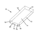
- FIG. 1 an upper part of an outer housing of an ink cartridge in a perspective view
- FIG. 2 a lower part of the outer housing of the ink cartridge according to FIG. 1 in a perspective view
- FIG. 3 an ink cartridge with suspensions for bags in the bottom part in a perspective view
- FIG. 4 an ink cartridge with inserted ink bag in a front view
- FIG. 5 a profiled cutting for an upper part of the ink cartridge in a top view
- FIG. 6 a profiled cutting for a lower part of the ink cartridge in a top view
- FIG. 7 a profiled cutting for a reinforcing layer for an upper part according to FIG. 5 of the ink cartridge in a top view
- FIG. 8 a a schematic representation of a first embodiment of an ink bag with support plate
- FIG. 8 b a schematic representation of a second embodiment of an ink bag with support plate
- FIG. 9 a schematic sectional view of an exemplary embodiment of an ink cartridge with moulding means.
- FIG. 1 shows an embodiment of an upper part 10 of an outer housing 2 of an ink cartridge 1 in a perspective view.
- the upper part 10 lies on the lid 11 .
- the upper part 10 comprises two parallel longitudinal side wall layers 13 and 14 .
- the two longitudinal side wall layers are connected at their ends by a rear wall layer 12 and a front wall layer 15 which is parallel thereto.
- the rear wall layer 12 and the front wall layer 15 are located opposite each other, the longitudinal side wall layers 13 and 14 are arranged orthogonally to the front wall layer 15 and to the rear wall layer 12 respectively.
- the lid 11 and the wall layers 12 to 15 of the upper part 10 of the ink cartridge 1 are produced from corrugated board.
- the upper part 10 forms a basin or shell-like geometry.
- the receiving openings 19 serve to receive extensions on the printer side.
- the cross section of the receiving openings 19 in each case is larger than the cross section of the extensions on the printer side, as a result of which a contactless receiving of the extensions on the printer side can take place and consequently, on inserting the ink cartridge on the printer, no additional friction through the extensions on the printer side is generated on the ink cartridge, which in turn prevents possible complications such as a jamming of the ink cartridge and/or plastic deformation in particular of the board of the outer housing.
- a rectangular recess 20 for an ink outlet piece is provided in the middle of the front wall layer 15 .
- the recess does not extend as far as to the lid 11 , but a region filled by corrugated board of the front wall layer 15 is filled out between them.
- the recess for the ink outlet piece however extends as far as to the edge, since from this direction the ink outlet piece is placed in the recess and a region filled out with corrugated board of the front wall layer 15 would be in the way of a simple placement.
- This recess directly adjoins the front wall layer 15 .
- the recess 18 is continuous on the side facing away from the lid 11 , since the guide arm (of the lower part) is received from this direction.
- FIG. 2 shows a lower part 30 of the ink cartridge 1 associated with the upper part 10 shown in FIG. 1 , likewise in a perspective view.
- the lower part 30 in this view lies on the bottom 31 .
- the lower part 30 In transverse direction (in the direction of the width extension of the cartridge), the lower part 30 is bounded by the two parallel longitudinal side wall layers 33 and 34 .
- the lower part 30 In longitudinal direction, is bounded by the front wall layer 35 and the rear wall layer 32 which is parallel thereto.
- the bottom 31 and the wall layers 32 to 35 of the lower part 30 of the ink cartridge 1 are produced from corrugated board.
- the lower part 30 likewise forms a basin or shell-like geometry.
- a rectangular recess 40 for the ink outlet piece 5 is additionally provided.
- the guiding means in form of the guide arm 36 are attached, which guides the ink cartridge in a guide rail (not shown) on the printer side.
- a rectangular recess 42 for a filling level indicator (not shown) is provided.
- reinforcing layers are provided in the upper and lower part, which are fixed to upper and lower shell with suitable adhesive means.
- the lid 11 is further strengthened through the reinforcing layer 50 .
- the reinforcing layer 50 is preferentially likewise of corrugated board and has a corrugation direction which is orthogonal to the corrugation direction of the respective portions, to which it is attached.
- the lower part from FIG. 1 and the upper part 10 from FIG. 2 are plugged together.
- the area of the lid 11 in its longitudinal and width extension is larger than the area of the bottom 31 , as a result of which the side wall layers 13 and 14 of the upper part 10 lie outside round about the side wall layers 33 and 34 of the lower part 30 .
- two-layered side walls of the ink cartridge 1 are thus formed through the upper part 10 and the lower part 30 .
- an ink container 4 Prior to assembling, an ink container 4 is inserted in the lower part 30 .
- the ink outlet piece 5 of the ink container 4 is fixed in the recess 40 of the lower part 30 .
- a first groove 6 is provided on the ink outlet piece 5 of the ink container 4 .
- the ink container 4 is additionally fixed on the ink outlet piece in the recess 20 of the upper part 10 .
- the groove 6 can be likewise provided which in its width is then adapted to the sum of the thicknesses of front wall layer 35 of the lower part 30 and thickness of the front wall layer 15 of the upper part 10 .
- a second groove 7 can be provided, which is only adapted to the thickness of the front wall layer 15 of the upper part 10 . Accordingly, the groove 6 in this case is adapted in its width to the thickness extension of the front wall layer 35 of the lower part 30 .
- FIG. 3 the lower part 30 from FIG. 2 is shown with additional positive connection means 43 .
- These positive connection means 43 designed as suspension space the ink container 4 from the front wall layer 35 of the lower part 30 .
- the groove 6 in the ink outlet piece can also support itself against the positive connection means 33 or parts thereof (alternatively or additionally to the front wall of the ink cartridge).
- a support plate 8 is fixed on the ink container 4 in a first embodiment.
- a filling level indicator 9 extends which is run in the direction of the filling level indicator recess 42 .
- the height position of the filling level indicator 9 can be gauged through the filling level indicator recess 42 in the bottom 31 of the lower part 30 from outside of the ink cartridge 1 .
- the filling level indicator 9 extends obliquely from the support plate 8 in the direction of the filling level indicator recess 42 in the bottom 31 of the outer housing 1 .
- the filling level indicator 9 touches the outer housing in a plane that is closer to the bottom 31 than the support plate 8 .
- the filling level indicator goes around the ink container and ends, depending on the filling level of the ink container, either (within or outside the housing) near the filling level indicator recess 42 or in the latter.
- FIG. 8 b shows a second embodiment of an ink container 4 , on which a support plate 8 is fixed.
- a filling level indicator first extends in the direction of the lid 11 , then runs in a plane that is parallel to the support plate 8 in the direction of a side wall of the outer housing 2 and subsequently in the drawing downwards in the direction of the bottom 31 , in particular in the direction of the filling level indicator recess 42 .
- the filling level of the ink container 4 can be gauged from the outside, in particular by a printer.
- FIG. 4 shows the front view of an assembled ink cartridge, which comprises the upper part according to FIG. 1 , the lower part according to FIG. 2 and an inserted ink container.
- the front wall of the ink cartridge which comprises the front wall layer 15 of the upper part 10 and the front wall layer 35 of the lower part 30 .
- the front wall 15 comprises a rectangular receiving opening 19 each for the contactless receiving of any printer extensions.
- the front wall layer 35 of the lower part 30 located behind the front wall layer 15 of the upper part is partially exposed towards the outside.
- the front wall layer 35 of the lower part 30 comprises receiving openings 39 , which directly lie behind the receiving openings 19 of the upper part 10 .
- it comprises a recess 40 which on the one hand exposes the ink outlet piece 5 towards the outside and on the other hand exposes a region which is not visible above the ink outlet piece 5 towards the outside.
- FIGS. 5 to 7 show individual parts of a second embodiment of the invention in a folded-open view. This representation substantially corresponds to the cutting of the individual parts from a flat corrugated board.
- FIG. 5 shows a cutting for an upper part 10 of board in the folded-open view.
- the upper part 10 is produced from a continuous piece of corrugated board, in which the corrugation direction in the Figure runs in horizontal direction.
- the lid 11 Centrally in the drawing, the lid 11 is provided, which comprises a recess 27 for an insert part which is not shown.
- a front wall layer 15 is arranged in the drawing plane on the right adjoining the lid 11 .
- a front wall folding edge 24 is provided, on which the front wall layer 15 can be folded relative to the lid 11 .
- a rectangular ink outlet piece recess 20 and likewise rectangular receiving opening 19 for the contactless receiving of extensions on the printer side are provided.
- the longitudinal side wall layers 13 and 14 which are separated from the lid 11 through longitudinal side wall folding edges 25 a and 25 b , wherein the longitudinal side wall layers 13 and 14 can be folded at the longitudinal side wall folding edges 25 a and 25 b relative to the lid 11 .
- a rear wall layer 12 is provided, wherein between them a rear wall folding edge 26 is provided, at which the rear wall layer 12 can be folded relative to the lid 11 .
- the folding edges 24 to 26 can be punched into the corrugated board to facilitate folding over.
- Adjoining the front wall layer and the longitudinal side wall layers 13 and 14 are located two front wall gluing regions 28 a and 28 b , which are each joined to the longitudinal side wall layers 13 and 14 respectively (foldable/bendable), but are separated from the front wall layer 15 through a recess.
- two rear wall gluing regions 29 a and 29 b are located, which are each joined to the longitudinal side wall layers 13 and 14 respectively (foldable/bendable), but which are separated from the rear wall layer 12 through a recess.
- an oblique guide flank 21 is formed through which the second longitudinal side wall layer 14 narrows towards the front wall layer 15 in its height extension to an inlet height.
- recesses are provided in each case, through which the front wall layer 15 and the front wall gluing region are narrowed to the inlet height.
- a recess 18 (See also FIG. 1 ) for a guide arm 36 , which is fastened to the lower part 30 , is provided.
- FIG. 6 shows a cutting for a lower part 30 of board in the folded-open view.
- the lower part is of a continuous piece of corrugated board, in which the corrugation direction in the Figure runs in horizontal direction.
- a front wall layer 35 adjoins the bottom 31 , which comprises a rectangular ink outlet piece recess 40 and likewise rectangular receiving openings 39 for the contactless receiving of extensions on the printer side. Between bottom 31 and front wall layer 35 a front wall folding edge 44 is provided.
- a rear wall layer 32 is provided, wherein between them a rear wall folding edge 46 is provided, through which the rear wall layer 32 can be folded relative to the bottom 31 .
- the folding edges 44 to 46 can be punched into the corrugated board to facilitate folding over.
- two front wall gluing regions 48 a and 48 b Adjoining the front wall layer 35 and the longitudinal side wall layers 33 and 34 , two front wall gluing regions 48 a and 48 b are located which are each joined to the longitudinal side wall layers 33 and 34 respectively (foldable/bendable), but which are separated from the front wall layer 35 through a recess.
- rear wall gluing regions 49 a and 49 b adjoining the rear wall layer 32 and the longitudinal side wall layers 33 and 34 are located two rear wall gluing regions 49 a and 49 b , which are each joined to the longitudinal side wall layers 33 and 34 respectively (foldable/bendable), but which are separated from the rear wall layer 32 through a recess.
- an oblique guide flank 41 is formed, through which the second longitudinal side wall layer 34 in its height extension (vertically in the Figure) narrows towards the front wall layer 15 to an inlet height.
- recesses are each provided, through which the front wall layer 35 and the front wall gluing region 48 a are narrowed towards the inlet height.
- a recess 38 for a guide arm 36 configured as angle (not shown), which following the folding of the lower part 30 is fixed to the latter, wherein a leg is positioned through the recess 38 and at least one other one is fastened to an inner surface of the lower part 30 , in particular glued.
- FIG. 7 shows a reinforcing layer 50 , as are used for reinforcing the upper part shown in FIG. 5 .
- the corrugation direction runs vertically in the Figure and is thus perpendicular to the corrugation direction of the upper part.
- the individual parts are first brought into their three-dimensional final form through folding and gluing.
- the longitudinal side wall layers 13 and 14 (including the gluing regions 28 a / 28 b and 29 a / 29 b connected to these), the front wall layer 15 and the rear wall layer 12 are folded upwards at the respective folding edges 24 to 26 in the Figure plane.
- the front wall gluing regions 28 b and 28 b are now arranged so that they abut the front wall layer 15 in a contacting manner.
- the front wall gluing regions 28 a and 28 b are subsequently glued to the front wall layer 15 through suitable adhesive means.
- the rear wall gluing regions 29 a and 29 b are arranged so that they abut the rear wall in a contacting manner and can be glued to the rear wall layer.
- the longitudinal side wall layers 13 and 14 , the front wall layer 15 and the rear wall layer 12 are each at a right angle to the plane extension of the lid 11 in their plane extension, wherein the longitudinal side wall layers 13 and 14 are parallel to each other and the front wall layer 15 and the rear wall layer 12 are parallel to each other.
- the reinforcing layer 50 is fixed to the lid 11 .
- a reinforcing layer can be provided on the bottom 31 analogously to the lid 11 .
- the longitudinal side walls 33 and 34 (including the gluing regions 48 a / 48 b and 49 a / 49 b connected to these), the front wall 35 and the rear wall 32 are first folded upwards at the respective folding edges 44 to 46 in the Figure plane.
- the front wall gluing regions 48 a and 48 b are now arranged so that they abut the front wall layer 35 in a contacting manner. They are subsequently glued to the front wall layer 35 through a suitable adhesive means.
- the rear wall gluing regions 49 a and 49 b are arranged so that they abut the rear wall layer in a contacting manner and can be glued to the rear wall.
- the longitudinal side wall layers 33 and 34 , the front wall layer 35 and the rear wall layer 32 are each at a right angle to the plane extension of the bottom 31 in their plane extension, wherein the longitudinal side wall layers 33 and 34 are parallel to each other and the front wall layer 35 and the rear wall layer 32 are parallel to each other.
- an ink container is placed in the lower part and fixed if required, and upper part and lower part subsequently plugged together.
- the cartridge On inserting in a printer, the cartridge is guided into its desired position through two mechanisms.
- the guide arm On the one hand, the guide arm is located on the first longitudinal side wall, which interacts with a guide on the printer side and brings the ink cartridge in position.
- the guide flank 21 and 41 serves as a further correction means.
- FIG. 9 shows a detail of a further exemplary embodiment of an ink cartridge 1 according to the invention together with a detail of an inkjet printer 101 , wherein the ink cartridge comprises an outer housing 2 of a cellulose material, on which guiding means 136 in the form of an axial extension are attached. Furthermore, the ink cartridge comprises an ink outlet piece 5 which is designed so that it can interact with interface means 104 on the printer side which comprise puncturing means 105 with a puncturing needle, so that an ink-conductive connection between ink cartridge 1 and printer 101 is established.
- the guiding means 136 formed as axial extension in this case are produced from a plastic having a greater stability, i.e. a greater stiffness and hardness than the material of the outer housing 2 .
- the axial extension comprises two conical centring means, which on inserting the ink cartridge 1 in the inkjet printer 101 , interact in insertion direction R with counter guiding means 137 on the printer side formed as conical depressions so that an ink outlet piece 5 is aligned or centred relative to the puncturing means 105 in the form of a puncturing needle.
Landscapes
- Ink Jet (AREA)
Applications Claiming Priority (4)
| Application Number | Priority Date | Filing Date | Title |
|---|---|---|---|
| DE102010055783.8 | 2010-12-23 | ||
| DE102010055783 | 2010-12-23 | ||
| DE102010055783A DE102010055783B3 (de) | 2010-12-23 | 2010-12-23 | Tintenkartusche für Tintenstrahldrucker |
| PCT/EP2011/073950 WO2012085269A2 (de) | 2010-12-23 | 2011-12-23 | Tintenkartusche für tintenstrahldrucker |
Publications (2)
| Publication Number | Publication Date |
|---|---|
| US20140111583A1 US20140111583A1 (en) | 2014-04-24 |
| US9162467B2 true US9162467B2 (en) | 2015-10-20 |
Family
ID=45757363
Family Applications (1)
| Application Number | Title | Priority Date | Filing Date |
|---|---|---|---|
| US13/997,346 Expired - Fee Related US9162467B2 (en) | 2010-12-23 | 2011-12-23 | Ink cartridge for inkjet printers |
Country Status (6)
| Country | Link |
|---|---|
| US (1) | US9162467B2 (de) |
| EP (1) | EP2523811B1 (de) |
| BR (1) | BR112013015739A2 (de) |
| DE (2) | DE102010055783B3 (de) |
| ES (1) | ES2445919T3 (de) |
| WO (1) | WO2012085269A2 (de) |
Cited By (1)
| Publication number | Priority date | Publication date | Assignee | Title |
|---|---|---|---|---|
| JP2016187878A (ja) * | 2015-03-30 | 2016-11-04 | セイコーエプソン株式会社 | カートリッジ、及び、液体噴射システム |
Families Citing this family (2)
| Publication number | Priority date | Publication date | Assignee | Title |
|---|---|---|---|---|
| JP6277641B2 (ja) * | 2013-09-17 | 2018-02-14 | セイコーエプソン株式会社 | 液体収容体 |
| DE102017215431A1 (de) * | 2017-09-04 | 2019-03-07 | Krones Ag | Direktdruckmaschine und -verfahren zur Bedruckung von Behältern mit einem mehrfarbigen Direktdruck |
Citations (11)
| Publication number | Priority date | Publication date | Assignee | Title |
|---|---|---|---|---|
| US5221935A (en) * | 1990-02-15 | 1993-06-22 | Canon Kabushiki Kaisha | Waste ink receiving cartridge and ink recording apparatus using said cartridge |
| US5307091A (en) | 1992-03-16 | 1994-04-26 | Lexmark International, Inc. | Jet ink refill supply |
| JPH06211273A (ja) | 1992-10-28 | 1994-08-02 | Dainippon Printing Co Ltd | バッグインカートン |
| US5666146A (en) | 1991-05-27 | 1997-09-09 | Seiko Epson Corporation | Ink cartridge for ink jet recording apparatus |
| US6219933B1 (en) | 1997-06-06 | 2001-04-24 | Riso Kagaku Corporation | Container for fluid and fluid level detector using the same |
| US6402308B1 (en) | 1999-06-24 | 2002-06-11 | Canon Kabushiki Kaisha | Liquid supply system and liquid supply vessel used for the same |
| US6505926B1 (en) * | 2001-08-16 | 2003-01-14 | Eastman Kodak Company | Ink cartridge with memory chip and method of assembling |
| US20050151813A1 (en) | 2004-01-14 | 2005-07-14 | Brother Kogyo Kabushiki Kaisha | Ink pack, ink cartridge and ink supplying device |
| US20060038865A1 (en) | 2004-08-20 | 2006-02-23 | Konica Minolta Medical & Graphic, Inc. | Ink cartridge for inkjet recording apparatus |
| US7093710B2 (en) * | 2002-10-31 | 2006-08-22 | Brother Kogyo Kabushiki Kaisha | Ink-package assembly, and method of producing the same |
| US7488059B1 (en) * | 2004-11-02 | 2009-02-10 | Nu-Kote International, Inc. | Enclosure for ink reservoir bag |
Family Cites Families (3)
| Publication number | Priority date | Publication date | Assignee | Title |
|---|---|---|---|---|
| JPS6254625B2 (de) | 1978-06-26 | 1987-11-16 | Eamatsuku Kuraiajeniku Mashiinarii Inc | |
| US5369429A (en) * | 1993-10-20 | 1994-11-29 | Lasermaster Corporation | Continuous ink refill system for disposable ink jet cartridges having a predetermined ink capacity |
| JP3624927B2 (ja) * | 1996-10-07 | 2005-03-02 | セイコーエプソン株式会社 | インクカートリッジ |
-
2010
- 2010-12-23 DE DE102010055783A patent/DE102010055783B3/de not_active Expired - Fee Related
-
2011
- 2011-02-07 DE DE202011002459U patent/DE202011002459U1/de not_active Expired - Lifetime
- 2011-12-23 US US13/997,346 patent/US9162467B2/en not_active Expired - Fee Related
- 2011-12-23 EP EP11820860.2A patent/EP2523811B1/de not_active Not-in-force
- 2011-12-23 ES ES11820860.2T patent/ES2445919T3/es active Active
- 2011-12-23 WO PCT/EP2011/073950 patent/WO2012085269A2/de active Application Filing
- 2011-12-23 BR BR112013015739A patent/BR112013015739A2/pt not_active IP Right Cessation
Patent Citations (11)
| Publication number | Priority date | Publication date | Assignee | Title |
|---|---|---|---|---|
| US5221935A (en) * | 1990-02-15 | 1993-06-22 | Canon Kabushiki Kaisha | Waste ink receiving cartridge and ink recording apparatus using said cartridge |
| US5666146A (en) | 1991-05-27 | 1997-09-09 | Seiko Epson Corporation | Ink cartridge for ink jet recording apparatus |
| US5307091A (en) | 1992-03-16 | 1994-04-26 | Lexmark International, Inc. | Jet ink refill supply |
| JPH06211273A (ja) | 1992-10-28 | 1994-08-02 | Dainippon Printing Co Ltd | バッグインカートン |
| US6219933B1 (en) | 1997-06-06 | 2001-04-24 | Riso Kagaku Corporation | Container for fluid and fluid level detector using the same |
| US6402308B1 (en) | 1999-06-24 | 2002-06-11 | Canon Kabushiki Kaisha | Liquid supply system and liquid supply vessel used for the same |
| US6505926B1 (en) * | 2001-08-16 | 2003-01-14 | Eastman Kodak Company | Ink cartridge with memory chip and method of assembling |
| US7093710B2 (en) * | 2002-10-31 | 2006-08-22 | Brother Kogyo Kabushiki Kaisha | Ink-package assembly, and method of producing the same |
| US20050151813A1 (en) | 2004-01-14 | 2005-07-14 | Brother Kogyo Kabushiki Kaisha | Ink pack, ink cartridge and ink supplying device |
| US20060038865A1 (en) | 2004-08-20 | 2006-02-23 | Konica Minolta Medical & Graphic, Inc. | Ink cartridge for inkjet recording apparatus |
| US7488059B1 (en) * | 2004-11-02 | 2009-02-10 | Nu-Kote International, Inc. | Enclosure for ink reservoir bag |
Non-Patent Citations (1)
| Title |
|---|
| International Search report Jun. 25, 2012. |
Cited By (1)
| Publication number | Priority date | Publication date | Assignee | Title |
|---|---|---|---|---|
| JP2016187878A (ja) * | 2015-03-30 | 2016-11-04 | セイコーエプソン株式会社 | カートリッジ、及び、液体噴射システム |
Also Published As
| Publication number | Publication date |
|---|---|
| WO2012085269A2 (de) | 2012-06-28 |
| EP2523811B1 (de) | 2013-11-13 |
| ES2445919T3 (es) | 2014-03-06 |
| DE202011002459U1 (de) | 2012-04-02 |
| WO2012085269A3 (de) | 2012-08-30 |
| US20140111583A1 (en) | 2014-04-24 |
| DE102010055783B3 (de) | 2012-06-14 |
| EP2523811A2 (de) | 2012-11-21 |
| BR112013015739A2 (pt) | 2018-05-15 |
Similar Documents
| Publication | Publication Date | Title |
|---|---|---|
| US9162467B2 (en) | Ink cartridge for inkjet printers | |
| CN1182969C (zh) | 用于喷墨打印系统的墨盒和其组装方法 | |
| AU718867B2 (en) | Ink tank, production process of ink tank and ink-jet printing apparatus | |
| US9033462B2 (en) | Waste ink tank and inkjet printer | |
| WO2007037536A1 (en) | Ink cartridge and method for replacing ink reservoir element in ink cartridge | |
| WO2007037451A9 (en) | Ink cartridge, ink jet recording system and set of ink cartridges | |
| US11591153B1 (en) | Bifurcated trilobular packaging element | |
| EP2280828B1 (de) | Tintenbehälterträger | |
| CN102069965A (zh) | 纸巾盒 | |
| CN210063902U (zh) | 一种包装精密仪器的纸箱 | |
| JP5435261B2 (ja) | 収容容器 | |
| CN109203710A (zh) | 液体收容单元 | |
| WO2007037449A1 (en) | Ink cartridge, and system including ink cartridge and ink jet recording apparatus | |
| US20130258006A1 (en) | Ink cartridge | |
| JP5430111B2 (ja) | カップホルダ | |
| EP1772272B1 (de) | Tintenpatrone, Hauptgehäuseanordnung und Nachfülleinheit | |
| CN102196973B (zh) | 包装装置以及包括擦拭器和擦拭器包装装置的组件 | |
| CN206579984U (zh) | 一种地台板组合箱 | |
| CN215437352U (zh) | 一种纸塑包装盒的侧缓冲结构 | |
| KR20110066922A (ko) | 패키징 장치 및 2개 이상의 와이퍼 블레이드와 이 와이퍼 블레이드용의 패키징 장치를 포함하는 조립체 | |
| WO2007037528A9 (en) | Ink cartridge and ink jet recording apparatus | |
| CN117262424A (zh) | 包装托盘和包装结构 | |
| CN101112819A (zh) | 可更换墨水盒的打印机构 | |
| CN210853295U (zh) | 一种快速成型的一体式箱体结构 | |
| CN212860857U (zh) | 一种不带引导孔的标签色带盒 |
Legal Events
| Date | Code | Title | Description |
|---|---|---|---|
| AS | Assignment |
Owner name: MARABU GMBH & CO. KG, GERMANY Free format text: ASSIGNMENT OF ASSIGNORS INTEREST;ASSIGNORS:MARCEDDU, CONSTANZE;WIESEBROCK, UWE;ZECH, ULRICH;SIGNING DATES FROM 20131026 TO 20131028;REEL/FRAME:031584/0025 |
|
| STCF | Information on status: patent grant |
Free format text: PATENTED CASE |
|
| FEPP | Fee payment procedure |
Free format text: MAINTENANCE FEE REMINDER MAILED (ORIGINAL EVENT CODE: REM.); ENTITY STATUS OF PATENT OWNER: LARGE ENTITY |
|
| LAPS | Lapse for failure to pay maintenance fees |
Free format text: PATENT EXPIRED FOR FAILURE TO PAY MAINTENANCE FEES (ORIGINAL EVENT CODE: EXP.); ENTITY STATUS OF PATENT OWNER: LARGE ENTITY |
|
| STCH | Information on status: patent discontinuation |
Free format text: PATENT EXPIRED DUE TO NONPAYMENT OF MAINTENANCE FEES UNDER 37 CFR 1.362 |
|
| FP | Expired due to failure to pay maintenance fee |
Effective date: 20191020 |