US915744A - Pump. - Google Patents
Pump. Download PDFInfo
- Publication number
- US915744A US915744A US34912406A US1906349124A US915744A US 915744 A US915744 A US 915744A US 34912406 A US34912406 A US 34912406A US 1906349124 A US1906349124 A US 1906349124A US 915744 A US915744 A US 915744A
- Authority
- US
- United States
- Prior art keywords
- pump
- valve
- cylinder
- head
- piston
- Prior art date
- Legal status (The legal status is an assumption and is not a legal conclusion. Google has not performed a legal analysis and makes no representation as to the accuracy of the status listed.)
- Expired - Lifetime
Links
- XLYOFNOQVPJJNP-UHFFFAOYSA-N water Substances O XLYOFNOQVPJJNP-UHFFFAOYSA-N 0.000 description 9
- 230000008878 coupling Effects 0.000 description 6
- 238000010168 coupling process Methods 0.000 description 6
- 238000005859 coupling reaction Methods 0.000 description 6
- 238000010276 construction Methods 0.000 description 5
- 241001269524 Dura Species 0.000 description 1
- 229940084430 four-way Drugs 0.000 description 1
- 210000004907 gland Anatomy 0.000 description 1
- 229920000136 polysorbate Polymers 0.000 description 1
Images
Classifications
-
- F—MECHANICAL ENGINEERING; LIGHTING; HEATING; WEAPONS; BLASTING
- F04—POSITIVE - DISPLACEMENT MACHINES FOR LIQUIDS; PUMPS FOR LIQUIDS OR ELASTIC FLUIDS
- F04B—POSITIVE-DISPLACEMENT MACHINES FOR LIQUIDS; PUMPS
- F04B47/00—Pumps or pumping installations specially adapted for raising fluids from great depths, e.g. well pumps
Definitions
- the object of our invention is to provide an improved construction of double acting pump which willbe formedof com aratively few and simple parts that are dura le in construction, and efficient in operation, andthe invention consists in certain constructions, arrangements and combinations of'the parts hereinafter described and claimed.
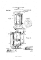
- Figure 1. is a perspective view of my improved pump; and, Fig. 2 is a vertical sectional view thereof, parts being shown in side elevation. Fig. 3 is a top plan view of the stand.
- the top I) of the head is in the plane of the outer flange a and is formed near its margin with openings extending therethrough, as shown, to establish communication between the head 2 and the pump cylinder and to provide a central portion that is disposed above and in spaced relation to the Valve 4 and is arranged to constitute a stop to limit the upward movement of such valve and also to prevent the lower end of the piston rod from coming in contact with such valve upon the down stroke of the piston.
- a piston 6, which may be constructed of a series of disks with interposed downwardly and upwardly facing leathers or cups, is adapted to be held against a collar 7 on the piston rod 9, by means of the nut 8.
- the said piston rod extends up through a stuffing box 10 which is held in the seat that is provided for it in the cap piece 11, bolted or otherwise secured to the top of the cylinder.
- the gland 10 of the stuffing box is provided in its upper surface with a depression 10 adapted to catch any water that may be forced through the stuffing box upon the upward movement of the piston or plunger rod, and such water may be then sucked down in the pump when the plunger rod descends.
- piston rod 9 may be operated by any suitable power, such as a Wind mill or engine of any character as well as by hand.
- the plunger as being operable manually and as secured at its upper end to a pump handle 12 which is pivoted to the upper end of the rocking link 13. This link is supported at its lower end upon a bracket 14 or lug projecting out from the head 2.
- the contracted portion of the stand 1 is provided below the check valve 4 with an outwardly opening passage 15 from which the low er laterally extending member of the branch suction pipe 15 extends.
- This lower member of said pi e is connected by an elbow coupling to tie vertically extending member of the said branch suction pipe and the coupling contains an angle check valve 16 deslgned to open inwardly, that is, toward the cylinder 5 to which it is connected by means of the union 17.
- the pump cylinder 5 is provided with an upper outlet opening 19, and a lower outlet opening 20. ⁇ Vithin these respective openings are screwed valve casings, 21, 22, each of which contains an outwardly opening check valve.
- valve casing 21 passage through these valve casings that are controlled by the said check valve and which lead from the outlet openings 19 and 20 are connected together by the outlet pipe 23 having an elbow 23 at one end which connects it to the valve casing 22 and a fourway coupling 24 so as to connect it to the valve casing 21.
- a cylinder 25 providing an air chamber is secured to one member of this four-way coupling 24, while another member of the coupling may be secured to the final outlet pipe designed to lead the water to any desired point.
- 26 designates a drain which is secured to the contracted portion of the pump head below the check valve 4 and which is provided with a suitable valve or stop cock by which it may be opened whenever necessary to drain the pump.
- the actuating parts 01' the pump may be placed at any reasonable distance from the pi )6 or water supply.
- a pum) of the character described comprising a iollow stand consisting of a flared base 1, a 'l'lared head 2 and an intermediate contracted portion 0, a main suction pipe passing through the base and terminating in the contracted portion, an upwardly opening valve 4 located centrally within and pivoted to the head and controlling the communication between the latter and the contracted portion 0, a drain valve leading from the contracted portion ol the stand intermediate ol the ends thereof a branch suction pipe 15 connecting the intermediin'e portion of the contracted part c with the upper end of the pump and having an inwardly opening valve 16, a pump cylinder 5 secured to and supported upon the head, a piston (i reci rocating within the cylinder, and an out et pipe 23 having connection with opposite ends of the pump cylinder and provided near its ends with outwardly opening valves 21 and 22, the stand being formed at the upper end of the head with a top l'orincd near its margin with openings extending therethrough to establish coinmunication ht tween
Landscapes
- Engineering & Computer Science (AREA)
- Mechanical Engineering (AREA)
- General Engineering & Computer Science (AREA)
- Details Of Reciprocating Pumps (AREA)
- Reciprocating Pumps (AREA)
Description
E. A; 00'sTBPHBNs-& 13,1). snow. I
PUMP. APPLIUATiON TILED DEG-22, 1906.
Patented Mar.- 23,1909.
THE NORRIS PETERS cm, wasnmmu. D. c.
UNITED STATES PATENT oFFIon.
ELGIN A. OOSTEPHENS AND DESKIN D. SNOW, 'OF NUBIA, TEXAS.
PUMP.
Specification of Letters Patent.
Patented March 23, 1909.
Application filed December 22, 1906. Serial No. 349,124. 1
the United States, residing at Nubia, in the county of Taylor and State of Texas, have lnvented certain new and useful Improvements in Pumps, of which the following is a specification.
The object of our invention is to provide an improved construction of double acting pump which willbe formedof com aratively few and simple parts that are dura le in construction, and efficient in operation, andthe invention consists in certain constructions, arrangements and combinations of'the parts hereinafter described and claimed.
For a full understanding of the invention and the merits thereof and also to acquire a knowledge of the details of construction of the means for efiecting the result, reference is to be had to the following description and accompanying drawings, in which:
Figure 1.is a perspective view of my improved pump; and, Fig. 2 is a vertical sectional view thereof, parts being shown in side elevation. Fig. 3 is a top plan view of the stand.
Corresponding and like parts are referred to in the following description and indicated in all the views of the drawings by the same reference characters. 7
The pump consisting of a cylinder and a piston arranged to operate therein, is mounted upon a stand which is preferably hollow, as shown, and consists of a flared base 1, a flared head 2 and an intermediate contracted portion a. The outer flange a provided at the upper end of the head, receives the lower flanged end of the pump cylinder, the two being secured by bolts passed through openings formed therein. The main suction pipe 3 connects with the contracted ortion c of the stand and passes through the ase 1 thereof. An upwardly opening valve 4 controls the direct communication between the suction pipe 3 and the hollow head 2, the valve being of the pivoted type and being located centrally within the hollow head and connected thereto. The top I) of the head is in the plane of the outer flange a and is formed near its margin with openings extending therethrough, as shown, to establish communication between the head 2 and the pump cylinder and to provide a central portion that is disposed above and in spaced relation to the Valve 4 and is arranged to constitute a stop to limit the upward movement of such valve and also to prevent the lower end of the piston rod from coming in contact with such valve upon the down stroke of the piston.
A piston 6, which may be constructed of a series of disks with interposed downwardly and upwardly facing leathers or cups, is adapted to be held against a collar 7 on the piston rod 9, by means of the nut 8. The said piston rod extends up through a stuffing box 10 which is held in the seat that is provided for it in the cap piece 11, bolted or otherwise secured to the top of the cylinder. Preferably the gland 10 of the stuffing box is provided in its upper surface with a depression 10 adapted to catch any water that may be forced through the stuffing box upon the upward movement of the piston or plunger rod, and such water may be then sucked down in the pump when the plunger rod descends. It is manifest that the piston rod 9 may be operated by any suitable power, such as a Wind mill or engine of any character as well as by hand. In the present instance, we have shown the plunger as being operable manually and as secured at its upper end to a pump handle 12 which is pivoted to the upper end of the rocking link 13. This link is supported at its lower end upon a bracket 14 or lug projecting out from the head 2.
The contracted portion of the stand 1 is provided below the check valve 4 with an outwardly opening passage 15 from which the low er laterally extending member of the branch suction pipe 15 extends. This lower member of said pi e is connected by an elbow coupling to tie vertically extending member of the said branch suction pipe and the coupling contains an angle check valve 16 deslgned to open inwardly, that is, toward the cylinder 5 to which it is connected by means of the union 17.
In addition to the opening 18, the pump cylinder 5 is provided with an upper outlet opening 19, and a lower outlet opening 20. \Vithin these respective openings are screwed valve casings, 21, 22, each of which contains an outwardly opening check valve. The
passage through these valve casings that are controlled by the said check valve and which lead from the outlet openings 19 and 20 are connected together by the outlet pipe 23 having an elbow 23 at one end which connects it to the valve casing 22 and a fourway coupling 24 so as to connect it to the valve casing 21. A cylinder 25 providing an air chamber is secured to one member of this four-way coupling 24, while another member of the coupling may be secured to the final outlet pipe designed to lead the water to any desired point.
26 designates a drain which is secured to the contracted portion of the pump head below the check valve 4 and which is provided with a suitable valve or stop cock by which it may be opened whenever necessary to drain the pump.
From the foregoing description in connection with the accompanying drawing, it will be seen that as the plunger or piston 6 moves upwardly, it will suck water into the lower end of the cylinder 5 the check valve 4 opening during this movement. At the same time water that has, by a previous down stroke been drawn into the upper end of the pump cylinder, will be forced out through the outlet 19 in the upper end of the cylinder and out throu h the four Way coupling 24 to the desired point. During this nip-stroke, it is manifest that the check valve within the casing 22 will be closed as will also the check valve within the casing 16.
Upon the down stroke of the plunger, it is manifest that the water drawn into the lower end of the cylinder will be forced outwardly through the outlet opening 20 and through the pipe 23, while water will be supplied to the upper end 01' the cylinder at the same time by means of the suction which will re suit in drawing the water from the main suction pipe 3 and thence through the branch suction pipe 15 and check valve 16 and. inlet opening 18 'By a construction of pump as herein described and shown, it is obvious that a comparatively short stroke will be sufficient, that the pump can be repaired without pulling up any underground pipes or disturbing the working parts that are not of easy access,
and that the actuating parts 01' the pump may be placed at any reasonable distance from the pi )6 or water supply.
Having thus described the invention, what is claimed as new is:
A pum) of the character described, comprising a iollow stand consisting of a flared base 1, a 'l'lared head 2 and an intermediate contracted portion 0, a main suction pipe passing through the base and terminating in the contracted portion, an upwardly opening valve 4 located centrally within and pivoted to the head and controlling the communication between the latter and the contracted portion 0, a drain valve leading from the contracted portion ol the stand intermediate ol the ends thereof a branch suction pipe 15 connecting the intermediin'e portion of the contracted part c with the upper end of the pump and having an inwardly opening valve 16, a pump cylinder 5 secured to and supported upon the head, a piston (i reci rocating within the cylinder, and an out et pipe 23 having connection with opposite ends of the pump cylinder and provided near its ends with outwardly opening valves 21 and 22, the stand being formed at the upper end of the head with a top l'orincd near its margin with openings extending therethrough to establish coinmunication ht tween the head and the pump cylinder and to provide a central portion located above the valve 4 and constituting a stop to limit the upward movement thereol' and to prevent the piston h'on coming in contact with such valve on a down stroke.
In testimony whereof we allix our signatures in presence of two witnesses. w
men A. ccs'rrriuirs, [1 DESKIN ll. snow. I a] Viitncsses:
W v'v Vv nnnrnn, J H. CUMMINGS.
Priority Applications (1)
| Application Number | Priority Date | Filing Date | Title |
|---|---|---|---|
| US34912406A US915744A (en) | 1906-12-22 | 1906-12-22 | Pump. |
Applications Claiming Priority (1)
| Application Number | Priority Date | Filing Date | Title |
|---|---|---|---|
| US34912406A US915744A (en) | 1906-12-22 | 1906-12-22 | Pump. |
Publications (1)
| Publication Number | Publication Date |
|---|---|
| US915744A true US915744A (en) | 1909-03-23 |
Family
ID=2984180
Family Applications (1)
| Application Number | Title | Priority Date | Filing Date |
|---|---|---|---|
| US34912406A Expired - Lifetime US915744A (en) | 1906-12-22 | 1906-12-22 | Pump. |
Country Status (1)
| Country | Link |
|---|---|
| US (1) | US915744A (en) |
Cited By (1)
| Publication number | Priority date | Publication date | Assignee | Title |
|---|---|---|---|---|
| US3077162A (en) * | 1956-05-24 | 1963-02-12 | Aerojet General Co | Vibratory pump |
-
1906
- 1906-12-22 US US34912406A patent/US915744A/en not_active Expired - Lifetime
Cited By (1)
| Publication number | Priority date | Publication date | Assignee | Title |
|---|---|---|---|---|
| US3077162A (en) * | 1956-05-24 | 1963-02-12 | Aerojet General Co | Vibratory pump |
Similar Documents
| Publication | Publication Date | Title |
|---|---|---|
| US862867A (en) | Pneumatic pumping apparatus. | |
| US2280626A (en) | High-low pressure pumping system | |
| US915744A (en) | Pump. | |
| US1909659A (en) | Oil well pumping apparatus | |
| US1129362A (en) | Automatic pneumatic pump. | |
| US2039570A (en) | Pump | |
| US523240A (en) | Double-acting pump | |
| US1347806A (en) | Well cable-pump | |
| US536415A (en) | Vacuum-pump | |
| US724569A (en) | Relay-pump. | |
| US795892A (en) | Water-supply system. | |
| US980050A (en) | Pump. | |
| US1861843A (en) | Gas lift pump | |
| US666641A (en) | Pumping apparatus. | |
| US972390A (en) | Air-pumping attachment for water-pumps. | |
| US1321709A (en) | Drain-storage pump | |
| US338147A (en) | Hieam field | |
| US990886A (en) | Pump. | |
| US542766A (en) | Interchangeable pump | |
| US889733A (en) | Water-balanced pump. | |
| US381808A (en) | peters | |
| US379543A (en) | Half to thomas dobbins | |
| US772692A (en) | Well attachment. | |
| US1449569A (en) | Pump or pumping apparatus | |
| US1347033A (en) | Pneumatic pump |