US9150349B2 - Storage apparatus having tank with tapered bottom and axle assembly - Google Patents
Storage apparatus having tank with tapered bottom and axle assembly Download PDFInfo
- Publication number
- US9150349B2 US9150349B2 US14/463,576 US201414463576A US9150349B2 US 9150349 B2 US9150349 B2 US 9150349B2 US 201414463576 A US201414463576 A US 201414463576A US 9150349 B2 US9150349 B2 US 9150349B2
- Authority
- US
- United States
- Prior art keywords
- assembly
- holding tank
- tank
- base portion
- portable
- Prior art date
- Legal status (The legal status is an assumption and is not a legal conclusion. Google has not performed a legal analysis and makes no representation as to the accuracy of the status listed.)
- Active
Links
Images


Classifications
-
- B—PERFORMING OPERATIONS; TRANSPORTING
- B65—CONVEYING; PACKING; STORING; HANDLING THIN OR FILAMENTARY MATERIAL
- B65D—CONTAINERS FOR STORAGE OR TRANSPORT OF ARTICLES OR MATERIALS, e.g. BAGS, BARRELS, BOTTLES, BOXES, CANS, CARTONS, CRATES, DRUMS, JARS, TANKS, HOPPERS, FORWARDING CONTAINERS; ACCESSORIES, CLOSURES, OR FITTINGS THEREFOR; PACKAGING ELEMENTS; PACKAGES
- B65D88/00—Large containers
- B65D88/26—Hoppers, i.e. containers having funnel-shaped discharge sections
- B65D88/30—Hoppers, i.e. containers having funnel-shaped discharge sections specially adapted to facilitate transportation from one utilisation site to another
-
- B—PERFORMING OPERATIONS; TRANSPORTING
- B65—CONVEYING; PACKING; STORING; HANDLING THIN OR FILAMENTARY MATERIAL
- B65D—CONTAINERS FOR STORAGE OR TRANSPORT OF ARTICLES OR MATERIALS, e.g. BAGS, BARRELS, BOTTLES, BOXES, CANS, CARTONS, CRATES, DRUMS, JARS, TANKS, HOPPERS, FORWARDING CONTAINERS; ACCESSORIES, CLOSURES, OR FITTINGS THEREFOR; PACKAGING ELEMENTS; PACKAGES
- B65D90/00—Component parts, details or accessories for large containers
- B65D90/0093—Devices for cleaning the internal surfaces of the container and forming part of the container
-
- B—PERFORMING OPERATIONS; TRANSPORTING
- B65—CONVEYING; PACKING; STORING; HANDLING THIN OR FILAMENTARY MATERIAL
- B65D—CONTAINERS FOR STORAGE OR TRANSPORT OF ARTICLES OR MATERIALS, e.g. BAGS, BARRELS, BOTTLES, BOXES, CANS, CARTONS, CRATES, DRUMS, JARS, TANKS, HOPPERS, FORWARDING CONTAINERS; ACCESSORIES, CLOSURES, OR FITTINGS THEREFOR; PACKAGING ELEMENTS; PACKAGES
- B65D90/00—Component parts, details or accessories for large containers
- B65D90/12—Supports
- B65D90/18—Castors, rolls, or the like; e.g. detachable
-
- B—PERFORMING OPERATIONS; TRANSPORTING
- B65—CONVEYING; PACKING; STORING; HANDLING THIN OR FILAMENTARY MATERIAL
- B65D—CONTAINERS FOR STORAGE OR TRANSPORT OF ARTICLES OR MATERIALS, e.g. BAGS, BARRELS, BOTTLES, BOXES, CANS, CARTONS, CRATES, DRUMS, JARS, TANKS, HOPPERS, FORWARDING CONTAINERS; ACCESSORIES, CLOSURES, OR FITTINGS THEREFOR; PACKAGING ELEMENTS; PACKAGES
- B65D2590/00—Component parts, details or accessories for large containers
- B65D2590/0091—Ladders
-
- B—PERFORMING OPERATIONS; TRANSPORTING
- B65—CONVEYING; PACKING; STORING; HANDLING THIN OR FILAMENTARY MATERIAL
- B65D—CONTAINERS FOR STORAGE OR TRANSPORT OF ARTICLES OR MATERIALS, e.g. BAGS, BARRELS, BOTTLES, BOXES, CANS, CARTONS, CRATES, DRUMS, JARS, TANKS, HOPPERS, FORWARDING CONTAINERS; ACCESSORIES, CLOSURES, OR FITTINGS THEREFOR; PACKAGING ELEMENTS; PACKAGES
- B65D88/00—Large containers
- B65D88/26—Hoppers, i.e. containers having funnel-shaped discharge sections
- B65D88/32—Hoppers, i.e. containers having funnel-shaped discharge sections in multiple arrangement
-
- Y—GENERAL TAGGING OF NEW TECHNOLOGICAL DEVELOPMENTS; GENERAL TAGGING OF CROSS-SECTIONAL TECHNOLOGIES SPANNING OVER SEVERAL SECTIONS OF THE IPC; TECHNICAL SUBJECTS COVERED BY FORMER USPC CROSS-REFERENCE ART COLLECTIONS [XRACs] AND DIGESTS
- Y10—TECHNICAL SUBJECTS COVERED BY FORMER USPC
- Y10T—TECHNICAL SUBJECTS COVERED BY FORMER US CLASSIFICATION
- Y10T137/00—Fluid handling
- Y10T137/6851—With casing, support, protector or static constructional installations
- Y10T137/6855—Vehicle
- Y10T137/691—With retractable or nonuse-positionable support wheel
Definitions
- the present invention relates generally to industrial equipment, and more particularly, to a storage apparatus for storing fluid materials.
- Holding tanks and other storage apparatuses are commonly used in industrial operations. Improvements to this technology are desired.
- a portable tank assembly that is movable between an operating position and a transport position that includes a tank assembly with a holding tank having an upper section that includes an upper wall and a lower section that includes a lower wall that tapers inwardly from the upper wall to form an orifice, a transport assembly that includes a base portion and an axle assembly.
- the base portion is affixed to the upper section of the holding tank, and the axle assembly includes wheels for transporting the holding tank along a surface, and a skid assembly that includes a skid plate configured to rest on a horizontal surface when the portable tank assembly is in the operating position and a plurality of legs connecting the skid plate to the holding tank.
- the base portion includes at least two base portion rail members and a plurality of base portion cross members connecting the base portion rail members
- the axle assembly includes a frame that rotationally supports an axle that includes wheels on opposite ends thereof
- the axle assembly includes at least two axle assembly rail members and a plurality of axle assembly cross members connecting the axle assembly rail members.
- the transport assembly includes at least two seat members extending between the base portion and the axle assembly, and in the operation position, at least a portion of the lower section of the holding tank is seated on the seat members.
- a first angle is defined between the upper wall and lower wall of the holding tank
- a second angle is defined between the base portion rail members and the seat members. The first angle and the second angle are approximately the same.
- the holding tank includes a rinse assembly that comprises a supply pipe and a wash ring secured to an inside surface of the holding tank, and the wash ring includes a plurality of openings defined therein.
- the plurality of openings comprises at least first and second sets of openings. The first set of openings is positioned between 1° and 45° counterclockwise from a top dead center of the wash ring and the second set of openings is positioned between 1° and 45° clockwise from a top dead center of the wash ring.
- the wash ring includes a plurality of brackets secured about the circumference thereof that are secured to the inside surface of the holding tank.
- the base portion includes a hitch assembly opposite the axle assembly and the tank assembly further comprises a recirculation manifold and recirculation return pipe.
- a tank assembly that includes a holding tank having an upper section that includes an upper wall and a lower section that includes a lower wall that tapers inwardly from the upper wall to form an orifice, and a rinse assembly that comprises a supply pipe and a wash ring with a plurality of openings defined therein secured to an inside surface of the holding tank.
- the plurality of openings comprises at least first and second sets of openings. The first set of openings is positioned between 1° and 45° counterclockwise from a top dead center of the wash ring and the second set of openings is positioned between 1° and 45° clockwise from a top dead center of the wash ring.
- a storage apparatus for storing fluid materials that includes a holding tank having an upper section and a lower section, the upper section comprising an upper wall with a non-tapered shape and the lower section comprising a lower wall with a tapered shape and a slope of approximately thirty degrees; and an axle assembly disposed adjacent to the holding tank, the axle assembly comprising a base that is affixable to the holding tank and at least one transport member for transporting the holding tank along a surface.
- FIG. 1 is a side elevational view of a portable tank assembly in the operational position in accordance with a preferred embodiment of the present invention
- FIG. 2 is a is a side elevational view of the portable tank assembly of FIG. 1 in the transport position
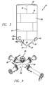
- FIG. 3 is a side elevational view of the holding tank
- FIG. 4 is a perspective view of the nozzle and piping assembly that is connected to the tip of the holding tank;
- FIG. 5 is a top elevational view of the recirculation manifold of the portable tank assembly of FIG. 1 ;
- FIG. 6 is a perspective view of the rinse assembly and showing the holding tank in hidden lines;
- FIG. 7A is a bottom view of the wash ring of the rinse assembly
- FIG. 7B is a top view of the wash ring of the rinse assembly
- FIG. 7C is a cross-sectional view taken along line 7 C- 7 C of FIG. 7A ;
- FIG. 8 is a cross sectional view taken along line 8 - 8 of FIG. 1 ;
- FIG. 9 is a perspective view of the railing assembly and showing the holding tank in hidden lines
- FIG. 10 is a perspective view of the transport assembly
- FIG. 11A is a rear elevational view of the portable tank assembly of FIG. 1 with the light bar exploded therefrom;
- FIG. 11B is a rear elevational view of the portable tank assembly of FIG. 1 with the light bar secured to the skid plate;
- FIG. 12 is a rear elevational view of an embodiment of the portable tank assembly of FIG. 1 where the skid plate includes lights embedded therein.
- references in this specification to “one embodiment” or “an embodiment” means that a particular feature, structure, or characteristic described in connection with the embodiment is included in at least one embodiment of the disclosure. Appearances of the phrase “in one embodiment” in various places in the specification do not necessarily refer to the same embodiment, nor are separate or alternative embodiments mutually exclusive of other embodiments. Moreover, various features are described which may be exhibited by some embodiments and not by others. Similarly, various requirements are described which may be requirements for some embodiments but not other embodiments.
- FIGS. 1-10 show a portable tank assembly 10 .
- the portable tank assembly 10 is movable between an operating position (see FIG. 1 ) and a transport position (see FIG. 2 ). It will be appreciated that, in a preferred embodiment, the transport position is approximately ninety degrees from the operating position. In use, the portable tank assembly 10 is more often in the operating position. Accordingly, any descriptive or orientation terms used herein, such as “upper,” “lower,” “vertical,” “horizontal,” etc. refer to the portable tank assembly 10 in the operating position (shown in FIG. 1 ) unless stated otherwise.
- the portable tank assembly 10 generally includes a holding tank assembly 12 , a transport assembly 14 and a skid assembly 16 .
- the holding tank assembly 12 includes a holding tank 17 comprised of a cylindrically shaped upper section 18 and a lower section 20 that depends downwardly and tapers inwardly from the upper section 18 .
- the lower section is conically shaped, as shown in the figures.
- both the upper section 18 and the lower section 20 can be comprised of walls that meet at an angle (e.g., a square cross-section).
- the wall(s) 21 of the upper section 18 are generally vertically oriented and have a non-tapered shape and the wall(s) 23 of the lower section 20 tapered inwardly from wall 21 .
- the upper section 18 also includes a cover or top 32 .
- the tapered shape of the lower section 20 forms a tip 22 .
- An orifice 24 is disposed at or near tip 22 .
- the contents of holding tank 17 can be emptied though orifice 24 via, for example, one or more nozzles 25 and relating piping 26 (described below), as shown in FIGS. 1 and 4 .
- the lower section 20 includes a top edge 20 a that abuts and is affixed to the bottom edge 18 a of the upper section 18 .
- the slope or angle A1 between the bottom edge 18 a of the upper section and the wall 23 of the lower section 20 can be approximately thirty degrees. In other embodiments, angle A1 can be between twenty degrees and forty degrees.
- This sloped lower section 20 allows the fluid material inside of holding tank 17 to flow to tip 22 more easily (compared to the prior art), especially for viscous materials. This helps minimize the amount of material held inside of holding tank 17 during each use. In addition, when holding tank 17 is ready to be transported to a new location, the amount of cleanup inside holding tank 17 is greatly reduced.
- the holding tank 17 can be used to store drilling mud, petroleum based products, water or any other fluid material used in industrial operations.
- Holding tank 17 may be made of any suitable material, including steel or plastic, and may be formed using any conventional technique.
- FIG. 3 shows the holding tank 17 with a plurality of seams 31 representing the welding together of a plurality of steel plates.
- holding tank 17 can have a 420 barrel capacity.
- this is not a limitation on the present invention and the holding tank interior 33 can have any desired capacity.
- Pipes 26 which are connected to nozzle 25 are used to transport the contents to a preferred destination.
- pipes 26 include suction for pulling the contents out of the bottom of the holding tank 17 and through tip 22 .
- the holding tank 17 includes a recirculation manifold 58 (see FIG. 5 ), which allows a plurality of holding tanks 17 to be connected. For example, tanks are often placed side by side in rows. The recirculation manifold allows the contents (e.g., mud) to be transferred and circulated between tanks.
- the recirculation manifold 58 includes four sections 58 a that form a ring (circular or square, as shown) that surrounds an exterior portion of the lower wall 23 of the holding tank 17 .
- Each of the sections 58 a includes a pipe or connection 58 b extending therefrom that allows other tanks to be positioned on up to all four sides. This provides a plurality of positioning options to connect tanks together.
- the holding tank assembly 12 includes a fill pipe 52 through which contents is injected into the holding tank 17 and an overflow pipe 53 that diverts excess contents to the exterior of the holding tank 17 (e.g., to the ground).
- the tank assembly preferably includes a supply pipe 36 for a rinse assembly 34 (described below) and a recirculation return pipe 55 that is connected to the recirculation manifold 58 .
- the recirculation return pipe 55 extends along the exterior of the holding tank 17 from the recirculation manifold 58 to an opening in the upper wall 21 of the tank and provides the ability to circulate or turnover the volume inside of the tank so that it is moving and kept mixed.
- the holding tank 17 includes various openings, inlets, outlets or hatches, etc. for access to the interior 33 of the holding tank 17 .
- the positioning, number and operation of the openings and hatches are not a limitation on the present invention.
- the holding tank assembly 12 preferably includes and inspection hatch 29 near the bottom of the holding tank 17 for when the portable tank assembly 10 is in the operating position and one or more inspection hatches 30 on the cover 32 for when the portable tank assembly 10 is in the transport position (see also FIG. 8 ).
- the cover 32 includes connections (e.g., threaded connections) for instrumentation 61 therein.
- Instrumentation such as a level transmitter or switch (for when the tank is being filled and it gets to a predetermined point an alarm can be sounded or a pump shut off), a radar gauge, a vent or breathing pipe for connecting adjacent tanks so that they all fill and empty at the same rate and all that.
- the center instrumentation connection 61 is used for a radar level indicator
- the adjacent one is used for a level switch
- the third one is for interconnecting the head space on adjacent tanks.
- FIG. 8 also shows a mechanical liquid level gauge 63 and a pressure relief valve 65 .
- the holding tank assembly 12 includes rinse assembly 34 for helping clean the interior 33 of the holding tank 17 .
- the rinse assembly 34 includes supply pipe 36 and wash ring 38 (round shaped in this embodiment, but could be square in an embodiment with walls that meet at angles) having a plurality of openings 40 therein.
- the wash ring 38 can be secured to the wall 21 of the upper section 18 via brackets 41 or the like.
- water or other liquid is delivered to the wash ring 38 via the supply pipe 36 (which extends through an opening in the holding tank 17 and is in communication with a fluid source at its distal end) and is forced through the openings 40 and sprayed on the inside of the holding tank 17 .
- FIGS. 7A-7B show an exemplary embodiment of a wash ring 38 that includes openings therein that the inventors have found provides thorough coverage of the interior of the holding tank 17 .
- the wash ring 38 includes four sets of openings 40 defined therein.
- the first set 40 a is approximately 30° from the top dead center (twelve o'clock) of the wash ring 38 in a counter-clockwise direction.
- the second set 40 b is approximately 45° from the top dead center of the wash ring 38 in a clockwise direction.
- the third set 40 c is approximately 120° from the top dead center of the wash ring 38 in a clockwise direction.
- the fourth set 40 d is approximately 150° from the top dead center of the wash ring 38 in a clockwise direction.
- the first set 40 a includes eight openings
- the second set 40 b includes eight openings
- the third set 40 c includes sixteen openings
- the fourth set 40 d includes seventeen openings.
- Each set of openings is spaced equally about the 360° wash ring 38 .
- the wash ring 38 is divided into first, second, third and fourth quadrants 38 a , 38 b , 38 c and 38 d .
- the first and second quadrants 38 a and 38 b are adjacent the upper wall 21 and the third and fourth quadrants 38 c and 38 d face away from the upper wall 21 .
- the first set 40 a of openings is positioned in the fourth quadrant 38 d
- the second set 40 b of openings is positioned in the first quadrant 38 a
- the third and fourth sets 40 c and 40 d of openings are positioned in the second quadrant 38 b.
- each of the openings from top dead center and the number of openings in each set is not a limitation on the present invention.
- the first set can be between 1° and 90° counterclockwise from top dead center
- the second set can be between 1° and 90° clockwise from top dead center
- the third and fourth sets can be between 90° and 180° from top dead center.
- Other openings can be included that are between 90° and 180° counterclockwise from top dead center.
- the holding tank assembly 12 includes a railing assembly 42 positioned on the cover 32 of the holding tank 17 .
- the railing assembly 42 comprises a floor 44 and a railing frame 46 and is permanently affixed to the cover 32 via brackets 48 or the like.
- the railing assembly 42 can be removable.
- the holding tank assembly 12 includes a ladder 50 for accessing the top of the holding tank 17 , and, in particular, the railing assembly 42 .
- portable tank assembly 10 includes transport assembly 14 disposed adjacent to holding tank assembly 12 .
- transport assembly 14 is permanently affixed to holding tank assembly 12 .
- transport assembly 14 is removeably affixable with respect to holding tank assembly 12 .
- the transport assembly 14 includes a base portion 60 and an axle assembly 62 that includes at least one transport member or wheel 64 for transporting the portable tank assembly 10 along a surface.
- the base portion 60 includes at least two base portion frame rail members 66 that are connected by a plurality of base portion cross members 68 .
- the base portion cross members 68 each include a saddle member 70 for supporting the holding tank 17 .
- each saddle member 70 has a concave surface with a shape similar to the outer surface of the upper section 18 .
- the base portion 60 also preferably includes a hitch assembly 72 that includes components for securing the transport assembly 14 to a truck.
- the hitch assembly 72 can include a jack 74 , a pintle hitch 76 , a cable bumper 78 , a front plate 80 , a pintle hitch plate gusset 82 , a winch riser 84 , a cable hook, Crosby eye bolt, marker lights 86 , pogo stick 88 and other components known in the trailer art.
- the axle assembly 62 preferably includes a frame 90 for rotationally supporting at least one axle 92 , at least two axle assembly rail members 91 , and axle assembly cross members 93 .
- the transport assembly includes at least two seat members 94 that extend between and connect the base portion 60 to the axle assembly 62 .
- the seat members 94 extend at an angle between and connect the base portion rail members 66 to the axle assembly rail members 91 .
- FIG. 1 when the portable tank assembly 10 is in the operation position, the lower section 20 of the holding tank 17 is seated on the seat members 94 . In the operation position, the angle A2 between the vertical wall 21 of the upper section 18 and the wall 23 of the lower section (see FIG.
- axle assembly 62 is approximately the same as the angle A3 between each base portion rail member 66 and the associated seat member 94 (see FIGS. 1 and 10 ).
- A2 and A3 are between about 100° and about 170°.
- A2 and A3 are between about 110° and about 130°.
- A2 and A3 are about 120°.
- the axle assembly 62 can include other components, such as an air tank 96 , brakes, marker lights, reflectors, etc.
- the skid assembly 16 includes a skid plate 100 and a plurality of legs 102 .
- the legs 102 are positioned about the periphery of the holding tank 17 and extend between and are connected to the skid plate 100 and the holding tank 17 .
- the base portion 60 is connected to the skid plate 100 (e.g., at frame 90 ).
- the skid plate 100 in the transport position, the skid plate 100 forms the back of the portable tank assembly 10 . Therefore, in a preferred embodiment, as is shown in FIGS. 11A-12 , the skid plate 100 includes brake and running lights 104 thereon. As shown in FIGS. 1 , 2 and 11 A- 11 B, in a preferred embodiment, the portable tank assembly 10 includes lighting 54 that is movable between a storage position ( FIG. 1 ), for when the portable tank assembly 10 is in the operation position and a use position ( FIGS. 2 and 11B ) for when the portable tank assembly is in the transport position. It will be appreciated that any lights discussed herein include wiring such that electricity can be provided thereto.
- the portable tank assembly 10 can include a power supply or a wire harness can be provided for connecting the wiring of the portable tank assembly 10 to the vehicle being used to transport the portable tank assembly 10 .
- the lighting 54 is a movable light bar 54 that is positioned on the skid plate 100 ( FIG. 11B ) in the use position and somewhere away from the skid plate 100 in the storage position so that it will not be crushed.
- FIGS. 11A-11B illustrate the skid plate 100 without the light bar 54 ( FIG. 11A ) and with the light bar 54 ( FIG. 11B ) secured thereto.
- the light bar 54 can be connected to the skid plate 100 in any desired way. As shown in FIG.
- the skid plate 100 includes openings 59 A therein that receive hooks or connectors 59 B on the back of the light bar 54 to connect the light bar 54 to the skid plate 100 .
- the light bar 54 is positioned on a storage plate 57 that is connected to the fill pipe 52 .
- the storage plate 57 includes openings therein similar to the openings 59 A in the skid plate 100 .
- Connection to the fill pipe 52 is not a limitation on the present invention.
- the light bar can be connected to another pipe, the trailer, the ladder or any other place where it can be stored away from the bottom of the skid plate 100 . Any type of connection to the skid plate 100 or storage plate 57 is within the scope of the present invention.
- the skid plate 100 can include lights 104 embedded therein or permanently attached thereto.
- the components of the portable tank assembly 10 are made of metal and are therefore secured to one another by welding. However, this is not a limitation on the present invention and the various components can be connected via other means.
- the skid plate 100 forms the base that supports the entire portable tank assembly 10 , as is shown in FIG. 1 .
- the words “comprise,” “comprising,” and the like are to be construed in an inclusive sense, as opposed to an exclusive or exhaustive sense; that is to say, in the sense of “including, but not limited to.”
- the terms “connected,” “coupled,” or any variant thereof means any connection or coupling, either direct or indirect, between two or more elements; the coupling of connection between the elements can be physical, logical, or a combination thereof.
- the words “herein,” “above,” “below,” and words of similar import when used in this application, shall refer to this application as a whole and not to any particular portions of this application.
Landscapes
- Engineering & Computer Science (AREA)
- Mechanical Engineering (AREA)
- Details Of Rigid Or Semi-Rigid Containers (AREA)
Abstract
Description
Claims (10)
Priority Applications (1)
| Application Number | Priority Date | Filing Date | Title |
|---|---|---|---|
| US14/463,576 US9150349B2 (en) | 2013-08-20 | 2014-08-19 | Storage apparatus having tank with tapered bottom and axle assembly |
Applications Claiming Priority (2)
| Application Number | Priority Date | Filing Date | Title |
|---|---|---|---|
| US201361868015P | 2013-08-20 | 2013-08-20 | |
| US14/463,576 US9150349B2 (en) | 2013-08-20 | 2014-08-19 | Storage apparatus having tank with tapered bottom and axle assembly |
Publications (2)
| Publication Number | Publication Date |
|---|---|
| US20150053292A1 US20150053292A1 (en) | 2015-02-26 |
| US9150349B2 true US9150349B2 (en) | 2015-10-06 |
Family
ID=52479283
Family Applications (1)
| Application Number | Title | Priority Date | Filing Date |
|---|---|---|---|
| US14/463,576 Active US9150349B2 (en) | 2013-08-20 | 2014-08-19 | Storage apparatus having tank with tapered bottom and axle assembly |
Country Status (2)
| Country | Link |
|---|---|
| US (1) | US9150349B2 (en) |
| WO (1) | WO2015026865A1 (en) |
Cited By (5)
| Publication number | Priority date | Publication date | Assignee | Title |
|---|---|---|---|---|
| US20150086308A1 (en) * | 2011-10-24 | 2015-03-26 | Solaris Oilfield Site Services Operating Llc | Fracture sand silo system and methods of deployment and retraction of same |
| US10300830B2 (en) | 2011-10-24 | 2019-05-28 | Solaris Oilfield Site Services Operating Llc | Storage and blending system for multi-component granular compositions |
| US10836568B2 (en) | 2011-10-24 | 2020-11-17 | Solaris Oilfield Site Services Operating Llc | Blender hopper control system for multi-component granular compositions |
| US11634274B2 (en) | 2019-03-22 | 2023-04-25 | Sandbox Enterprises, Llc | Bulk fluid storage container |
| USD996800S1 (en) | 2020-02-27 | 2023-08-29 | Sandbox Enterprises, Llc | Stackable bulk fluid storage container |
Families Citing this family (2)
| Publication number | Priority date | Publication date | Assignee | Title |
|---|---|---|---|---|
| US9777543B2 (en) * | 2013-08-27 | 2017-10-03 | Vertical Tank, Inc. | Device and method for multi-path flow from vertical hydraulic tank |
| CN113023132A (en) * | 2021-04-22 | 2021-06-25 | 胡定良 | Alkaline liquid holding vessel |
Citations (17)
| Publication number | Priority date | Publication date | Assignee | Title |
|---|---|---|---|---|
| US1260947A (en) * | 1917-05-11 | 1918-03-26 | Samuel A Siverts Jr | Water-tank-flushing cap and coil. |
| US3322347A (en) * | 1965-08-02 | 1967-05-30 | Carroll L Pierce | Dual purpose rotary mower washer and sprinkler device |
| US3407179A (en) * | 1965-05-12 | 1968-10-22 | Du Pont | Batch polymerization of aqueous diamine-dicarboxylic acid salt |
| US3625137A (en) | 1969-10-13 | 1971-12-07 | Up Right Inc | Tank trailer |
| US3934739A (en) * | 1974-02-13 | 1976-01-27 | Standard Havens, Inc. | Self-erecting surge storage system |
| US4241744A (en) * | 1979-07-02 | 1980-12-30 | Jordan Nathaniel Sr | Cleaning system for tanks |
| US4621972A (en) * | 1985-02-19 | 1986-11-11 | Grotte Walter D | Silo mover |
| US4626166A (en) * | 1985-11-06 | 1986-12-02 | Jolly Arthur E | Method for the placement of a trailer-mounted sand hopper |
| US4778111A (en) * | 1987-09-15 | 1988-10-18 | Leap Earl J | Tree soaker |
| US4872225A (en) * | 1988-09-06 | 1989-10-10 | Wagner John C | Cleaning apparatus and method for bath enclosures |
| US5644920A (en) | 1995-09-25 | 1997-07-08 | Rockwell International Corporation | Liquid propellant densification |
| US6386559B1 (en) | 2000-06-16 | 2002-05-14 | Peter R. Souza | Apparatus for securing and transporting a tank |
| US6616243B2 (en) | 2000-06-23 | 2003-09-09 | Carrier Transports, Inc. | Outrigger for stabilizing a dump trailer |
| US6715515B2 (en) | 2002-08-27 | 2004-04-06 | Deere & Company | Structure for loading chemicals into solution tanks |
| US7214028B2 (en) * | 2002-04-15 | 2007-05-08 | Boasso America Corporation | Method and apparatus for supplying bulk product to an end user |
| US20110203699A1 (en) | 2009-08-25 | 2011-08-25 | Rodgers Troy A | Chemical mixer |
| US8162164B2 (en) | 2007-04-19 | 2012-04-24 | Podd Stephen D | Bulk liquid transport system |
-
2014
- 2014-08-19 WO PCT/US2014/051751 patent/WO2015026865A1/en active Application Filing
- 2014-08-19 US US14/463,576 patent/US9150349B2/en active Active
Patent Citations (17)
| Publication number | Priority date | Publication date | Assignee | Title |
|---|---|---|---|---|
| US1260947A (en) * | 1917-05-11 | 1918-03-26 | Samuel A Siverts Jr | Water-tank-flushing cap and coil. |
| US3407179A (en) * | 1965-05-12 | 1968-10-22 | Du Pont | Batch polymerization of aqueous diamine-dicarboxylic acid salt |
| US3322347A (en) * | 1965-08-02 | 1967-05-30 | Carroll L Pierce | Dual purpose rotary mower washer and sprinkler device |
| US3625137A (en) | 1969-10-13 | 1971-12-07 | Up Right Inc | Tank trailer |
| US3934739A (en) * | 1974-02-13 | 1976-01-27 | Standard Havens, Inc. | Self-erecting surge storage system |
| US4241744A (en) * | 1979-07-02 | 1980-12-30 | Jordan Nathaniel Sr | Cleaning system for tanks |
| US4621972A (en) * | 1985-02-19 | 1986-11-11 | Grotte Walter D | Silo mover |
| US4626166A (en) * | 1985-11-06 | 1986-12-02 | Jolly Arthur E | Method for the placement of a trailer-mounted sand hopper |
| US4778111A (en) * | 1987-09-15 | 1988-10-18 | Leap Earl J | Tree soaker |
| US4872225A (en) * | 1988-09-06 | 1989-10-10 | Wagner John C | Cleaning apparatus and method for bath enclosures |
| US5644920A (en) | 1995-09-25 | 1997-07-08 | Rockwell International Corporation | Liquid propellant densification |
| US6386559B1 (en) | 2000-06-16 | 2002-05-14 | Peter R. Souza | Apparatus for securing and transporting a tank |
| US6616243B2 (en) | 2000-06-23 | 2003-09-09 | Carrier Transports, Inc. | Outrigger for stabilizing a dump trailer |
| US7214028B2 (en) * | 2002-04-15 | 2007-05-08 | Boasso America Corporation | Method and apparatus for supplying bulk product to an end user |
| US6715515B2 (en) | 2002-08-27 | 2004-04-06 | Deere & Company | Structure for loading chemicals into solution tanks |
| US8162164B2 (en) | 2007-04-19 | 2012-04-24 | Podd Stephen D | Bulk liquid transport system |
| US20110203699A1 (en) | 2009-08-25 | 2011-08-25 | Rodgers Troy A | Chemical mixer |
Non-Patent Citations (2)
| Title |
|---|
| International Search Report and Written Opinion issued on Dec. 4, 2014 in PCT/US14/51751. |
| Process Silos. Website with photos and manuals (online). Diversified Storage Systems, 2013 [retrieved on Jul. 17, 2013]. Retrieved from the Internet,URL:https://web.archive.org.web/20130717023611/http:www.cementsilos.com/index.php/projects/view/process-silos#web20130717023611im-/http://www.cement101.com/images-site>. |
Cited By (9)
| Publication number | Priority date | Publication date | Assignee | Title |
|---|---|---|---|---|
| US20150086308A1 (en) * | 2011-10-24 | 2015-03-26 | Solaris Oilfield Site Services Operating Llc | Fracture sand silo system and methods of deployment and retraction of same |
| US9499335B2 (en) * | 2011-10-24 | 2016-11-22 | Solaris Oilfield Site Services Operating, LLC | Fracture sand silo system and methods of deployment and retraction of same |
| US10300830B2 (en) | 2011-10-24 | 2019-05-28 | Solaris Oilfield Site Services Operating Llc | Storage and blending system for multi-component granular compositions |
| US10406962B2 (en) | 2011-10-24 | 2019-09-10 | Solaris Oilfield Site Services Operating Llc | Storage management system |
| US10625654B2 (en) | 2011-10-24 | 2020-04-21 | Solaris Oilfield Site Services Operating Llc | Delivery, storage and blending system for multi-component granular compositions |
| US10836568B2 (en) | 2011-10-24 | 2020-11-17 | Solaris Oilfield Site Services Operating Llc | Blender hopper control system for multi-component granular compositions |
| US11634274B2 (en) | 2019-03-22 | 2023-04-25 | Sandbox Enterprises, Llc | Bulk fluid storage container |
| US12024358B2 (en) | 2019-03-22 | 2024-07-02 | Sandbox Enterprises, Llc | Stackable bulk fluid storage container |
| USD996800S1 (en) | 2020-02-27 | 2023-08-29 | Sandbox Enterprises, Llc | Stackable bulk fluid storage container |
Also Published As
| Publication number | Publication date |
|---|---|
| WO2015026865A1 (en) | 2015-02-26 |
| US20150053292A1 (en) | 2015-02-26 |
Similar Documents
| Publication | Publication Date | Title |
|---|---|---|
| US9150349B2 (en) | Storage apparatus having tank with tapered bottom and axle assembly | |
| US10494170B2 (en) | Portable vertical fluid storage tank | |
| US7731462B2 (en) | Bulkhead for dividing a cargo container into two compartments | |
| US7856998B2 (en) | Portable fluid containment assembly | |
| US20210362637A1 (en) | Systems and methods for venting tanks to enhance transporting asphalt | |
| RU2572581C2 (en) | Erection of modular commercial structure | |
| US11091317B2 (en) | Vertical fluid storage tank with connecting ports | |
| US5873498A (en) | Railway locomotive fuel service truck | |
| CN102186749A (en) | Tank for storing fluid | |
| US20160039623A1 (en) | A dust suppression system for loading ship holds | |
| US8424914B2 (en) | Fluid container | |
| US20160130078A1 (en) | Bladder Systems for Dual Use of Truck Tanks | |
| US20160185321A1 (en) | Boat Trailer Rinse System | |
| CN103129708A (en) | Vessel provided with area for transmittng potentially dangerous liquid products | |
| US10040345B2 (en) | Spare tire fuel tank | |
| AU2007101010B4 (en) | Water storage tank in shipping container | |
| JP4903527B2 (en) | Large capacity foam water extinguishing system foam mixing equipment | |
| CN110498013A (en) | A kind of two deck-hatch cover of multi-purpose cargo ship and its mounting structure | |
| US20160075271A1 (en) | System for Converting Standard Truck to Water Tanker | |
| WO2016083438A1 (en) | Tank with sloshing bulkheads | |
| CN205198757U (en) | Integral fire engine | |
| AU2009101088A4 (en) | Fire-fighting water storage tank | |
| RU2797524C1 (en) | Multifunctional sectional tanker | |
| US20140251471A1 (en) | Vacuum Tank Trailer Discharge Port | |
| DE202020001841U1 (en) | Camping kitchen box for the trailer coupling of a car |
Legal Events
| Date | Code | Title | Description |
|---|---|---|---|
| AS | Assignment |
Owner name: BAKERCORP, CALIFORNIA Free format text: ASSIGNMENT OF ASSIGNORS INTEREST;ASSIGNORS:HALL, DAN;REAMY, DEREK;SIGNING DATES FROM 20140814 TO 20140827;REEL/FRAME:033734/0960 |
|
| AS | Assignment |
Owner name: BAKERCORP, CALIFORNIA Free format text: ASSIGNMENT OF ASSIGNORS INTEREST;ASSIGNOR:ADVANCED FLUID CONTAINMENT, LLC;REEL/FRAME:034943/0457 Effective date: 20150112 Owner name: ADVANCED FLUID CONTAINMENT, LLC, UTAH Free format text: ASSIGNMENT OF ASSIGNORS INTEREST;ASSIGNORS:EREKSON, STEPHEN;FLUCKIGER, MARK;HISLOP, CASEY;AND OTHERS;REEL/FRAME:034943/0423 Effective date: 20150112 |
|
| STCF | Information on status: patent grant |
Free format text: PATENTED CASE |
|
| AS | Assignment |
Owner name: UNITED RENTALS (NORTH AMERICA), INC., CONNECTICUT Free format text: MERGER;ASSIGNOR:BAKERCORP;REEL/FRAME:046553/0020 Effective date: 20180731 |
|
| AS | Assignment |
Owner name: BANK OF AMERICA, N.A., AS AGENT, CONNECTICUT Free format text: SUPPLEMENT TO AMENDED AND RESTATED U.S. INTELLECTUAL PROPERTY SECURITY AGREEMENT;ASSIGNOR:UNITED RENTALS (NORTH AMERICA), INC.;REEL/FRAME:047186/0935 Effective date: 20181002 |
|
| AS | Assignment |
Owner name: BANK OF AMERICA, N.A., AS AGENT, ILLINOIS Free format text: SECURITY INTEREST;ASSIGNORS:UNITED RENTALS (NORTH AMERICA), INC.;UNITED RENTALS, INC.;REEL/FRAME:047368/0862 Effective date: 20181031 |
|
| MAFP | Maintenance fee payment |
Free format text: PAYMENT OF MAINTENANCE FEE, 4TH YEAR, LARGE ENTITY (ORIGINAL EVENT CODE: M1551); ENTITY STATUS OF PATENT OWNER: LARGE ENTITY Year of fee payment: 4 |
|
| AS | Assignment |
Owner name: TRUIST BANK, NORTH CAROLINA Free format text: CORRECTIVE ASSIGNMENT TO CORRECT THE NAME OF THE ASSIGNEE PREVIOUSLY RECORDED ON REEL 061930 FRAME 0721. ASSIGNOR(S) HEREBY CONFIRMS THE SECURITY INTEREST;ASSIGNORS:UNITED RENTALS, INC.;UNITED RENTALS (NORTH AMERICA), INC.;REEL/FRAME:062815/0975 Effective date: 20221130 |
|
| MAFP | Maintenance fee payment |
Free format text: PAYMENT OF MAINTENANCE FEE, 8TH YEAR, LARGE ENTITY (ORIGINAL EVENT CODE: M1552); ENTITY STATUS OF PATENT OWNER: LARGE ENTITY Year of fee payment: 8 |