US9147243B2 - Method and apparatus for mapping image information of target object onto interface of the target object in magnetic resonance imaging - Google Patents
Method and apparatus for mapping image information of target object onto interface of the target object in magnetic resonance imaging Download PDFInfo
- Publication number
- US9147243B2 US9147243B2 US13/955,589 US201313955589A US9147243B2 US 9147243 B2 US9147243 B2 US 9147243B2 US 201313955589 A US201313955589 A US 201313955589A US 9147243 B2 US9147243 B2 US 9147243B2
- Authority
- US
- United States
- Prior art keywords
- target object
- interface
- image information
- information
- obtaining
- Prior art date
- Legal status (The legal status is an assumption and is not a legal conclusion. Google has not performed a legal analysis and makes no representation as to the accuracy of the status listed.)
- Active, expires
Links
Images


Classifications
-
- A—HUMAN NECESSITIES
- A61—MEDICAL OR VETERINARY SCIENCE; HYGIENE
- A61B—DIAGNOSIS; SURGERY; IDENTIFICATION
- A61B5/00—Measuring for diagnostic purposes; Identification of persons
- A61B5/05—Detecting, measuring or recording for diagnosis by means of electric currents or magnetic fields; Measuring using microwaves or radio waves
- A61B5/055—Detecting, measuring or recording for diagnosis by means of electric currents or magnetic fields; Measuring using microwaves or radio waves involving electronic [EMR] or nuclear [NMR] magnetic resonance, e.g. magnetic resonance imaging
-
- G—PHYSICS
- G06—COMPUTING OR CALCULATING; COUNTING
- G06T—IMAGE DATA PROCESSING OR GENERATION, IN GENERAL
- G06T7/00—Image analysis
- G06T7/0002—Inspection of images, e.g. flaw detection
- G06T7/0012—Biomedical image inspection
-
- G—PHYSICS
- G06—COMPUTING OR CALCULATING; COUNTING
- G06T—IMAGE DATA PROCESSING OR GENERATION, IN GENERAL
- G06T2207/00—Indexing scheme for image analysis or image enhancement
- G06T2207/10—Image acquisition modality
- G06T2207/10072—Tomographic images
- G06T2207/10088—Magnetic resonance imaging [MRI]
- G06T2207/10092—Diffusion tensor magnetic resonance imaging [DTI]
-
- G—PHYSICS
- G06—COMPUTING OR CALCULATING; COUNTING
- G06T—IMAGE DATA PROCESSING OR GENERATION, IN GENERAL
- G06T2207/00—Indexing scheme for image analysis or image enhancement
- G06T2207/30—Subject of image; Context of image processing
- G06T2207/30004—Biomedical image processing
- G06T2207/30016—Brain
Definitions
- the present disclosure relates to magnetic resonance imaging (MRI), and more particularly to a method and an apparatus for mapping image information of a target object onto an interface of the target object in magnetic resonance imaging (MRI).
- MRI magnetic resonance imaging
- Magnetic resonance imaging is a technology which involves positioning a target object in a space formed by a large magnet that generates a magnetic field, generating a radio frequency (RF) pulse to have protons included in the target object resonate, measuring differences in signals generated by tissues included in the target object, and reconstructing the measured differences through a computer to obtain an image of the target object.
- RF radio frequency
- the MRI has higher resolution and contrast than those of other imaging methods, for example, methods that use ultrasonic waves, and may provide a deep organ image and three-dimensional information in real time.
- the target object is not exposed to radiation. Therefore, the MRI is harmless to a human body and may obtain axial, sagittal, and coronal images without changing the position of the target object.
- the present invention provides a method and an apparatus for mapping image information of a target object onto an interface of the target object in magnetic resonance imaging (MRI).
- MRI magnetic resonance imaging
- the method may include obtaining the image information of the target object in a predetermined direction from the outside of the target object to the inside of the target object, analyzing the obtained image information, extracting one piece of the obtained image information based on the analysis result, and allotting the extracted image information onto the interface of the target object.
- the image information of the target object may include mean diffusivity (MD) information obtained from diffusion tensor imaging (DTI) of the target object.
- MD mean diffusivity
- DTI diffusion tensor imaging
- the image obtained using MRI may include an external interface and an internal interface of the target object.
- the predetermined direction may include a path connected between a predetermined point on the external interface and a point on the internal interface corresponding to the predetermined point on the external interface.
- Obtaining the image information of the target object may further include obtaining distance information of tissues included in the target object, detecting a first position on a path adjacent to the external interface and corresponding to a maximum value of the image information, detecting a second position on the path adjacent to the external interface and corresponding to a minimum value of the distance information, and obtaining a predetermined position range between the first position and the second position.
- the distance information may represent a distance from a reference point on at least one tissue included in the target object to another tissue.
- Analyzing the obtained image information may further include obtaining differential values for the obtained image information, detecting a third position on the path corresponding to a maximum differential value among the obtained differential values, and resetting the third position as an external interface of the target object.
- the third position may be included in the predetermined position range.
- Extracting one piece of the obtained image information based on the analysis result may include extracting image information corresponding to a fourth position separated from the third position by a predetermined distance in the predetermined position range.
- Allotting the extracted image information onto the interface of the target object may include generating an intermediate interface of the target object to correspond to the fourth position and allotting the extracted image information onto the intermediate interface.
- the intermediate interface may be positioned between the reset external interface and the internal interface.
- an apparatus for mapping image information of a target object onto an interface of the target object in MRI may include an information obtaining unit for obtaining the image information of the target object in a predetermined direction from the outside of the target object to the inside of the target object, an information analyzing unit for analyzing the obtained image information, an information extracting unit for extracting one piece of the obtained image information based on the analysis result, and an information allotting unit for allotting the extracted image information onto the interface of the target object.
- the image information of the target object may include MD information obtained from DTI of the target object.
- the image obtained from MRI may include an external interface and an internal interface of the target object.
- the predetermined direction may include a path connected between a predetermined point on the external interface and a point on the internal interface corresponding to the predetermined point on the external interface.
- the information obtaining unit may include a distance information obtaining unit for obtaining distance information of tissues included in the target object, a position detecting unit for detecting a first position on a path adjacent to the external interface and corresponding to a maximum value of the image information and a second position on the path adjacent to the external interface and corresponding to a minimum value of the distance information, and a position range obtaining unit for obtaining a predetermined position range between the first position and the second position.
- the distance information may represent a distance from a reference point on at least one tissue included in the target object to another tissue.
- the information analyzing unit may include a differential value obtaining unit for obtaining differential values for the obtained image information and an interface resetting unit for resetting a third position on the path corresponding to a maximum differential value among the obtained differential values as the external interface of the target object.
- the third position may be included in the predetermined position range and may be detected by the position detecting unit.
- the information extracting unit may extract image information corresponding to a fourth position separated from the third position by a predetermined distance in the predetermined position range.
- the information allotting unit may further include an intermediate interface generating unit for generating an intermediate interface of the target object to correspond to the fourth position.
- the information allotting unit may allot the extracted image information onto the intermediate interface.
- the intermediate interface may be positioned between the reset external interface and the internal interface.
- a computer readable recording medium in which a program for executing the above-described method by a computer is recorded may be provided.
- FIG. 1 illustrates an example of a surface based image analyzing method of the prior art
- FIG. 2 is a flowchart illustrating a method of mapping image information of a target object onto an interface of the target object in magnetic resonance imaging (MRI) according to an exemplary embodiment of the present invention
- FIG. 3 is a flowchart illustrating a method of obtaining image information of the target object according to the exemplary embodiment of the present invention
- FIG. 4 illustrates an example of a method of obtaining image information and distance information of the target object according to the exemplary embodiment of the present invention
- FIGS. 5A , 5 B and 5 C illustrate an example of a method of obtaining a predetermined position range according to the exemplary embodiment of the present invention
- FIG. 6 is a flowchart illustrating a method of analyzing obtained image information according to the exemplary embodiment of the present invention.
- FIG. 7A is a flowchart illustrating a method of extracting one piece of obtained image information according to the exemplary embodiment of the present invention.
- FIG. 7B is a flowchart illustrating a method of allotting extracted image information onto an interface of a target object according to the exemplary embodiment of the present invention.
- FIG. 8A illustrates an example of a method of analyzing obtained image information according to the exemplary embodiment of the present invention
- FIG. 8B illustrates an example of a method of extracting one piece of the obtained image information according to the exemplary embodiment of the present invention
- FIG. 9 illustrates an apparatus for mapping image information of the target object onto the interface of a target object in MRI according to the exemplary embodiment of the present invention
- FIG. 10 illustrates an apparatus for mapping image information of the target object onto an interface of the target object in MRI according to the exemplary embodiment of the present invention, showing the apparatus in FIG. 9 in greater detail;
- FIG. 11 illustrates an MRI apparatus implementing the apparatus of FIGS. 9-10 according to the exemplary embodiment of the present invention.
- magnetic resonance imaging refers to capturing an image of a target object obtained by a magnetic resonance (MR) and/or a nuclear magnetic resonance (NMR) principle.
- a target object according to an exemplary embodiment of the present invention may include a part of a human body, for example, organs such as a liver, a heart, a womb, a brain, a breast, and an abdomen.
- the target object according to the exemplary embodiment of the present invention may include a phantom.
- the phantom refers to a material having a very similar volume, density, and physical characteristics such as atomic numbers of elements and molecules in portions of a living thing, such as tissues.
- the phantom according to the exemplary embodiment of the present invention may include a spherical water phantom having similar characteristics to those of portions of a human body.
- the human cerebral cortex in which nerve cell bodies are gathered may perform very important functions such as a sensory function and a motor function.
- a microscopic change in the cerebral cortex research using mean diffusivity (MD) information obtained through diffusion MRI is being actively performed.
- MD mean diffusivity
- Diffusion MRI may refer to an image method that represents tissue distribution of a target object using anisotropy and directional properties in which water molecules included in the target object are diffused in a uniform direction.
- the diffusion MRI may include an image that represents the structure of a brain tissue using the motility and directional property of the water molecules included in the brain in a magnetic field.
- a volume based analyzing method and a surface based analyzing method may be used.
- the volume based analyzing method may include a region of interest (ROI) based analysis and a voxel based morphometry (VBM) analysis.
- ROI region of interest
- VBM voxel based morphometry
- the ROI based analysis includes a process of manually selecting a ROI of a target object by a user so that the ROI based analysis is very highly dependent on the user and that analysis accuracy of an image may vary with a skill of the user.
- the VBM analysis for investigating a pathological difference between local regions in a brain image field has a problem in that an analysis result of an image may vary with a registration success ratio. That is, the analysis result of the image may vary with the accuracy of registration of different images and the magnitude of smoothing performed to remove noise.
- the cerebral cortex has a very complicated structure in which furrows are repeated like waves.
- the volume based analyzing method cannot completely reflect the complicated structure of the cerebral cortex.
- a partial volume effect may be induced.
- the diffusion MRI may be used for detecting a change in the microtexture of the cerebral cortex.
- the change in the microtexture of the cerebral cortex may vary with the position of the voxel included in the image obtained by photographing the target object.
- the cerebral cortex includes a gray matter (GM) region.
- GM gray matter
- a value including not only the change in the microtexture of the cerebral cortex but also a change in the microtexture of the WM may be represented.
- CSF cerebrospinal fluid
- the measured value of the change in the microtexture of the cerebral cortex is affected so that a smaller value than the actual change in the microtexture of the cerebral cortex may be obtained.
- the partial volume effect may be obtained by the image registration of different images, the magnitude of smoothing, and the position of a voxel.
- a surface image of a target object may be generated by structural MRI for identifying the structure of the target object, and the structure of the furrows of the surface image is used during image registration so that the performance of image registration of different images may be improved.
- an interface between the WM and the GM region positioned in an internal part of the cerebral cortex and an interface between the CSF and the GM region positioned in an external part of the cerebral cortex are accurately divided and points corresponding to the internal interface and the external interface are found so that an intermediate interface may be generated along a path formed of the corresponding points.
- the intermediate interface may be included in the GM region.
- an interface is an actual or hypothetical surface dividing regions or belonging to a region or structure.
- the microscopic information and the macroscopic information of the cerebral cortex may be integrally analyzed.
- the surface image may include an image that represents the WM structure and an image that represents the GM structure.
- the surface image of each of right and left brains may consist of 81,920 triangular meshes.
- the MD information of the target object may be mapped onto the vertices of the triangular meshes of the generated surface image.
- image information of a target object may be accurately mapped onto the interface of the target object without obtaining an additional image such as an image including geometric distortion information.
- FIG. 1 shows an example of a surface based image analyzing method in the prior art.
- FIG. 1 for example, an image 100 obtained by performing registration of the images of the diffusion MRI and the structural MRI of a target object in the prior art is illustrated. As illustrated in FIG. 1 , an interface 300 of the target object in the diffusion MRI may not coincide with an interface 200 of the target object in the structural MRI.
- the interface 300 of the diffusion MRI may not coincide with the interface 200 of the structural MRI.
- Such non-coincidence may cause an error when image information of a voxel included in the image of the target object is mapped onto the surface of the target object.
- image information of the gray matter (GM) region of the cerebrum is to be mapped onto the interface of the GM region of the target object, due to the above-described non-coincidence between the interfaces, image information of CSF positioned further outside of the GM region of the cerebrum may be mapped onto the interface of the GM region of the target object.
- GM gray matter
- a method and an apparatus for improving the accuracy and reliability of mapping by detecting the accurate interface of the target object using the image information and distance information of the target object and by mapping the image information corresponding to the detected interface onto the detected interface are provided.
- FIG. 2 is a flowchart illustrating a method of mapping image information of a target object onto an interface of the target object in magnetic resonance imaging (MRI) according to the exemplary embodiment of the present invention.
- MRI magnetic resonance imaging
- a method of mapping image information of a target object onto an interface of the target object in MRI may include a step S 100 of obtaining the image information of the target object in a predetermined direction from the outside of the target object to the inside of the target object, a step S 200 of analyzing the obtained image information, a step S 300 of extracting one piece of the obtained image information, and a step S 400 of allotting the extracted image information onto the interface of the target object.
- the interface in the image obtained from MRI is then adjusted to move the interface in the image to a more accurate location and to compensate for imaging errors, and thus to generate an adjusted image which more accurately shows the interface of the target object, and the adjusted image is output in step S 500 , for example, from a display such as the user interface 31 and/or the image outputting unit 36 in FIG. 11 , as described below.
- the adjusted image may be output to a storage unit such as one of the storages 34 , 35 or transmitted, for example, over a network to another device for display, such as a remote terminal in the same or a different facility of the MRI apparatus implementing the present invention.
- the target object according to the exemplary embodiment of the present invention may include a human brain.
- the image information of the target object may be obtained in the predetermined direction from the inside of the target object to the outside of the target object.
- the image information of the target object may include mean diffusivity (MD) information obtained by diffusion tensor imaging (DTI) of the target object.
- MD mean diffusivity
- DTI diffusion tensor imaging
- DTI is one of the known analyzing techniques of MRI for quantitatively measuring the characteristics of the WM of the cerebrum and is obtained by the principle of free diffusion of water molecules that form a human body.
- Diffusion of the water molecules has a directional property in which the water molecules are diffused more in a specific direction due to nerve fiber bundles included in a brain tissue.
- the diffusion of the water molecules is mainly oriented in a direction where nerve fibers are aligned and the diffusion of the water molecules is restricted in a direction perpendicular to the nerve fibers.
- the directional property of cranial nerves may be visualized using DTI.
- the direction of the nerve fibers that form the WM of the cerebrum may be visually reconstructed.
- the image obtained by MRI may include the external interface and the internal interface of the target object.
- the external interface may be the interface between CSF and GM and the internal interface may be the interface between the GM and the WM.
- an image that represents a region in which the GM and the CSF of the cerebrum are divided may be generated using the external interface, and an image that represents a region in which the GM and the WM of the cerebrum are divided may be generated using the internal interface.
- the predetermined direction may include a linked path between a predetermined point of the external interface and a point in the internal interface corresponding to the point of the external interface.
- the image that represents the region in which the GM and the WM of the cerebrum are divided and the image that represents the region in which the GM and the CSF of the cerebrum are divided may consist of a plurality of three-dimensional points. Points of the image that represents the region in which the GM and the WM of the cerebrum are divided and points of the image that represents the region in which the GM and the CSF of the cerebrum are divided may be linked to each other, on a one to one correspondence basis, respectively. In this case, the thickness of the cerebral cortex in a selected direction may be defined by a distance between the two linked points.
- FIG. 3 is a flowchart illustrating a method of obtaining image information of a target object according to an exemplary embodiment of the present invention.
- the step S 100 in FIG. 2 of obtaining image information of a target object may further include a step S 110 of obtaining distance information of tissues included in the target object, a step S 120 of detecting a first position on a path adjacent to the external interface and corresponding to the maximum value of the image information, a step S 130 of detecting a second position on a path adjacent to the external interface and corresponding to the minimum value of the distance information, and a step S 140 of obtaining a predetermined position range between the first position and the second position, which will be described later with reference to FIG. 5 .
- the distance information according to the exemplary embodiment of the present invention may include information that represents a distance from a reference point on at least one tissue included in the target object to another tissue.
- the distance information may represent distances from a predetermined point of the WM of the cerebrum to the GM and the CSF of the cerebrum.
- distances from an axon included in the WM to the GM and the CSF may be included in the distance information.
- FIG. 4 illustrates an example of a method of obtaining image information and distance information of a target object according to the exemplary embodiment of the present invention.
- FIG. 4 For convenience sake and illustrative purposes, in FIG. 4 , only a portion of the block 500 of FIG. 1 is shown.
- a linked path 410 between a predetermined point 430 on an external interface 200 and a point 431 on an internal interface 220 corresponding to the point 430 is illustrated.
- the point 430 on the external interface 200 and the point 431 on the internal interface 220 may be linked to each other, on a one to one correspondence basis.
- a point 440 on an actual external interface 300 of a target object may be linked to a point 441 on an actual internal interface 320 of the target object.
- image information 450 of the target object may be obtained in a predetermined direction 410 .
- the image information 450 may be obtained based on a plane 420 including the predetermined point 430 on the external interface 200 .
- the X axis of the graph of FIG. 4 represents the path 410 toward the inside or the outside of the target object in predetermined units of length, such as units of millimeters (mm).
- mm millimeters
- the Y axis of the graph of FIG. 4 may be differently interpreted in accordance with a predetermined parameter.
- the image information 450 may include MD information.
- the Y axis represents the values of the MD information in units of mm 2 /sec.
- the present invention is not limited to the above.
- the graph of FIG. 4 may represent distance information 460 , represented by the light solid line.
- the distance information 460 may represent a distance from a reference point on at least one tissue included in the target object to another tissue.
- the distance information 460 may represent the distances from the axon included in the WM to the GM and the CSF.
- the Y axis in FIG. 4 may be represented in predetermined units of length, such as units of mm.
- the present invention is not limited to the above.
- the graph of FIG. 4 may represent the differential values 470 , represented by the bold solid line, for the image information 450 .
- the image information of the target object corresponding to the external interface 200 is to be allotted onto the actual external interface 300 of the target object. Therefore, it is important to detect the actual external interface 300 of the target object.
- the external interface 200 obtained from the structural MRI may not coincide with the actual external interface 300 of the target object in the diffusion MRI. That is, the external interface 200 and the internal interface 220 obtained from the structural MRI may be positioned further outside of the actual external interface 300 and the actual internal interface 320 of the target object in the diffusion MRI.
- the external interface 200 and the internal interface 220 obtained from the structural MRI may be positioned further inside than the actual external interface 300 and the actual internal interface 320 of the target object in the diffusion MRI.
- FIGS. 5A to 5C illustrate an example of a method of obtaining a predetermined position range according to the exemplary embodiment of the present invention.
- the distance information of tissues included in the target object may be obtained and the minima of the distance information may be obtained.
- the minima of the distance information may include the minimum values of the distance information. As illustrated in FIG. 5A , at least one minimum value may be obtained.
- the first position adjacent to the external interface 200 and corresponding to the maximum value 451 of the image information 450 may be detected.
- the maximum of the image information may include the maximum value of the image information
- the second position corresponding to the minimum value 461 adjacent to the external interface 200 may be detected from the minima of the distance information 460 .
- a predetermined position range 510 between the first position and the second position may be obtained.
- the predetermined position range 510 may be a position section in which a probability that the actual external interface 300 will exist is the highest.
- FIG. 6 illustrates a flowchart illustrating a method of analyzing obtained image information according to the exemplary embodiment of the present invention.
- the step S 200 in FIG. 2 of analyzing obtained image information may further include a step S 210 of obtaining differential values for the obtained image information, a step S 220 of detecting a third position on a path corresponding to the maximum differential value among the obtained differential values, and a step S 230 of resetting the third position as the external interface of a target object, which will be described later with reference to FIG. 8A .
- the third position according to the exemplary embodiment of the present invention may be included in the predetermined position range 510 shown in FIG. 5C .
- FIG. 7A is a flowchart illustrating a method of extracting one piece of the obtained image information according to the exemplary embodiment of the present invention.
- the step S 300 in FIG. 2 of extracting the one piece of the obtained image information based on the analysis result of the obtained image information according to the exemplary embodiment of the present invention may further include a step S 310 of extracting image information corresponding to a fourth position separated from the third position by a predetermined distance in the predetermined position range obtained in the step S 140 of FIG. 3 , which will be described later with reference to FIG. 8B .
- FIG. 7B is a flowchart illustrating a method of allotting extracted image information to the interface of a target object according to the exemplary embodiment of the present invention.
- the step S 400 in FIG. 2 of allotting extracted image information to the interface of a target object may further include a step S 410 of generating an intermediate interface of the target object to correspond to the fourth position and a step S 420 of allotting the extracted image information onto the intermediate interface.
- the intermediate interface may be an interface positioned between the reset external interface and the internal interface.
- the intermediate interface may be the interface included in the GM region of the cerebrum.
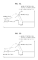
- FIG. 8A illustrates an example of a method of analyzing obtained image information according to the exemplary embodiment of the present invention.
- FIG. 8B illustrates an example of a method of extracting one piece of the obtained image information according to the exemplary embodiment of the present invention.
- Differential values 470 may be obtained for the image information 450 obtained in the step S 210 of FIG. 6 .
- the differential values 470 may include primary differential values that represent increases in the values of the image information in accordance with increases in distances on the path 410 of FIG. 4 .
- the present invention is not limited to the above.
- differential values 470 may be obtained that represent changes in the image information on the Y axis in accordance with changes in distances on the X axis.
- the image information 450 of the target object may change very rapidly on the interface of the target object. Therefore, the changes in the image information 450 may be quantitatively represented by the differential values 470 and the maximum value of the differential values may be estimated as the actual interface of the target object, for example, the interfaces 300 , 320 shown in FIG. 4 .
- a third position 480 shown in FIG. 8B may be detected, corresponding to the maximum differential value 471 of the obtained differential values 470 shown in FIG. 8A .
- the third position 480 may be the actual external interface 300 of the target object shown in FIG. 4 .
- a value 452 of the image information corresponding to the maximum differential value 471 may correspond to a MD value on the actual external interface 300 of the target object.
- the third position 480 shown in FIG. 8B may be reset as the external interface of the target object.
- the third position 480 may be estimated as the actual external interface 300 of the target object shown in FIG. 4 .
- the third position 480 may be preferably estimated as a predetermined point 440 on the actual external interface 300 of the target object, shown in FIG. 4 .
- the predetermined point 440 on the actual external interface 300 in FIG. 4 may refer to the vertex of each of the triangular meshes that form the surface image of the target object. That is, the predetermined point 440 on the actual external interface 300 may be the vertex at which the plurality of triangular meshes that form the surface image of the target object are connected to each other.
- the external interface 200 obtained from the structural MRI may not coincide with the actual external interface 300 of the target object. Therefore, in order to correlate the image information obtained from the external interface 200 to the actual external interface 300 , it is necessary to reset the position of the external interface 200 shown in FIG. 4 .
- non-coincidence between the interfaces may be reduced by resetting the position of the external interface of the target object related to the image information from the position 420 to the position 480 along the X axis. It is possible to improve a coincidence rate between the interfaces (for example, the interfaces 200 and 300 in FIG. 4 ) and to improve reliability of the image information of the target object by resetting the external interface 200 obtained by the structural MRI.
- the third position 480 may be included in the predetermined position range 510 .
- the step S 300 in FIG. 2 of extracting one piece of the obtained image information based on the analysis result of the image information may further include the step of extracting image information 453 shown in FIG. 8B corresponding to the fourth position separated from the third position 480 by a predetermined distance 490 in the predetermined position range 510 .
- the predetermined distance 490 may include an arbitrary distance between the external interface 200 and the internal interface 220 .
- the predetermined distance 490 may include a distance equal to half (1 ⁇ 2) of a distance between the external interface 200 and the internal interface 220 .
- the predetermined point 430 on the external interface 200 and the predetermined point 431 on the internal interface 220 shown in FIG. 4 , may be connected to each other.
- a distance between the point 430 and the point 431 on the target object may be previously stored in a storage unit of an apparatus to be described later with reference to FIG. 9 .
- the thickness of the cerebral cortex that may be represented by the distance between the point on the external interface and the point on the internal interface may be previously stored as numerical values representing the corresponding points.
- image information at a point moved toward the WM by half the thickness of the cerebral cortex formed of the GM of the cerebrum may be extracted.
- the predetermined distance 490 of FIG. 8B may be a distance from the reset external interface 480 to the point moved toward the WM by half the thickness of the cerebral cortex.
- the thickness of the cerebral cortex may be previously stored as described above.
- the image information 453 extracted according to the exemplary embodiment of the present invention may be included in the predetermined position range 510 as illustrated in FIG. 8B .
- the step S 400 of FIG. 2 of allotting the extracted image information onto the interface of the target object further includes the step S 410 of generating the intermediate interface of the target object to correspond to the fourth position and the step S 420 of allotting the extracted image information onto the intermediate interface.
- the intermediate interface according to the exemplary embodiment of the present invention may be positioned between the reset external interface and the internal interface.
- the fourth position according to the exemplary embodiment of the present invention may be positioned in the predetermined direction 410 corresponding to the point 453 of FIG. 8B . Since the image information 450 is obtained in the predetermined direction 410 , the position corresponding to the point 453 may be obtained from the image information 450 .
- the position corresponding to the point 453 may be preferably positioned between the external interface 300 and the internal interface 320 .
- the position corresponding to the point 453 may be positioned in the GM region. That is, the intermediate interface of the target object generated in the step S 410 of FIG. 7B may be an arbitrary interface included in the GM region.
- the image information extracted in the step S 420 of FIG. 7B may be allotted onto the intermediate interface.
- the image information 453 extracted in the position corresponding to the distance 490 moved by half of the thickness of the cerebral cortex in step S 310 may be allotted onto the interface of the GM region having a thickness of half of that of the cerebral cortex.
- the extracted image information 453 may be preferably allotted onto the vertex of each of the triangular meshes that form the interface of the GM region having the thickness of half of that of the cerebral cortex.
- image information is analyzed in a predetermined position range to detect the actual interface of a target object and the value of image information in a position separated from the detected interface by a predetermined distance, and such analyzed image information is obtained to allot the obtained value of the image information onto the interface corresponding to the corresponding position, and so to adjust the interface in the image obtained from MRI using the allotted image information. Therefore, the image information may be accurately mapped onto the target object in comparison with the prior art.
- FIG. 9 illustrates an apparatus for mapping image information of a target object onto the interface of the target object in MRI according to the exemplary embodiment of the present invention.
- the apparatus 900 for mapping image information of a target object to the interface of the target object in MRI may include an information obtaining unit 910 for obtaining the image information of the target object in a predetermined direction from the outside of the target object to the inside of the target object, an information analyzing unit 920 for analyzing the obtained image information, an information extracting unit 930 for extracting one piece of the obtained image information based on the analysis result, and an information allotting unit 940 for allotting the extracted image information onto the interface of the target object.
- the image information of the target object may include MD information obtained from DTI of the target object.
- the information obtaining unit 910 may be connected to or may include an MRI apparatus known in the art for obtaining such MRI information, including the MD information obtained from DTI of the target object.
- the MRI apparatus may include a magnet assembly 14 in which the target object, such as the patient or a portion of the patient, is positioned while on a table 15 .
- At least one main magnet 11 , at least one gradient coil 12 , and at least one RF coil 13 operate with a first signal generating unit 21 , a second signal generating unit 22 , a signal collecting unit 23 , and at least one of a first storage 34 and a second storage 35 , as well as with a user interface 31 , a control unit 32 , an image generating unit 33 , and an image outputting unit 36 to obtain magnetic resonance images in a manner known in the art, and to which the apparatus 900 and its components 910 - 940 are connected or included to perform the operations of the present invention.
- the user interface 31 and/or the image outputting unit 36 may include a display for displaying an image with an adjusted interface obtained from the operation of the present invention.
- the image obtained from MRI according to the exemplary embodiment of the present invention may include the external interface and the internal interface of the target object.
- the predetermined direction may include a path between a predetermined point on the external interface and a point on the internal interface corresponding to the predetermined point on the external interface, as described herein with reference to FIG. 4 .
- FIG. 10 illustrates an apparatus for mapping image information of a target object onto the interface of the target object in MRI according to the exemplary embodiment of the present invention, showing the apparatus 900 and its components 910 - 940 in FIG. 9 in greater detail.
- the information obtaining unit 910 may further include a distance information obtaining unit 911 , a position detecting unit 912 , and a position range obtaining unit 913 .
- the distance information obtaining unit 911 may obtain distance information of tissues included in the target object.
- the position detecting unit 912 may detect a first position on a path adjacent to the external interface and corresponding to the maximum value of the image information and a second position on a path adjacent to the external interface and corresponding to the minimum value of the distance information.
- the position range obtaining unit 913 may obtain a predetermined position range between the first position and the second position.
- the distance information according to the exemplary embodiment of the present invention may represent a distance from a reference point on at least one tissue included in the target object to another tissue.
- the information analyzing unit 920 may further include a differential value obtaining unit 921 and an interface resetting unit 922 .
- the differential value obtaining unit 921 may obtain differential values for obtained image information.
- the interface resetting unit 922 may reset a third position on a path corresponding to the maximum differential value among obtained differential values as the external interface of the target object.
- the third position may be included in the predetermined position range 510 , shown in FIGS. 5 C and 8 A- 8 B.
- the third position may be detected by the position detecting unit 912 included in the information obtaining unit 910 .
- the information extracting unit 930 may extract image information corresponding to a fourth position separated from the third position by a predetermined distance in the predetermined position range.
- the information extracting unit 930 is connected to the storage unit, such as one of the storages 34 , 35 in FIG. 11 , including information on the distance between the external interface 200 and the internal interface 220 as described above to obtain information on the distance between the interfaces. That is, the information extracting unit 930 may obtain the information stored in the storage unit on the distance between the external interface 200 and the internal interface 220 , with the information retrieved from the storage unit and may determine a predetermined distance by which separation from the reset interface is to be performed using the obtained distance information.
- the distance from the predetermined point 430 to the point 431 connected to the point 430 may be the thickness of the cerebral cortex for the corresponding points 430 and 431 .
- the information extracting unit 930 may determine the predetermined distance to be one half, one third, two thirds, one fourth, or any other factor of the thickness of the cerebral cortex by which separation from the reset interface is to be performed.
- the information extracting unit 930 may extract the value of the image information in the position separated from the reset interface by the above-described predetermined distance.
- the information allotting unit 940 may further include an intermediate interface generating unit 941 for generating an intermediate interface of the target object to correspond to the fourth position.
- the information allotting unit 940 may allot the extracted image information onto the intermediate interface.
- the intermediate interface may be positioned between the reset external interface and the internal interface.
- the intermediate interface generating unit 941 then generates an MR image having the accurate interface of the target object using the image information and distance information of the target object and by mapping the image information corresponding to the detected interface onto the detected interface.
- the apparatus 900 then outputs the generated MR image having the accurate interface, for example, to a display of the user interface 31 or the image outputting unit 36 of FIG. 11 .
- the content of the above-described method may be applied to the apparatus according to the exemplary embodiment of the present invention. Therefore, in the apparatus, description of the same content as that of the above-described method is omitted.
- the above-described exemplary embodiments of the present invention may be prepared by a program that may be executed by a computer and may be implemented by a general purpose digital computer that operates the program using computer readable recording media.
- the computer readable recording media include magnetic storage media (for example, a read-only memory (ROM), a floppy disk, and a hard disk, etc.), optical reading media (for example, a CD-ROM and a digital versatile disk (DVD), etc.), and carrier wave (for example, transmission through the Internet).
- magnetic storage media for example, a read-only memory (ROM), a floppy disk, and a hard disk, etc.
- optical reading media for example, a CD-ROM and a digital versatile disk (DVD), etc.
- carrier wave for example, transmission through the Internet.
- the above-described apparatus and methods according to the present invention can be implemented in hardware or firmware, or via the execution of software or computer code, or combinations thereof.
- the software or computer code can also be stored in a non-transitory recording medium such as a CD ROM, a RAM, a ROM whether erasable or rewritable or not, a floppy disk, CDs, DVDs, memory chips, a hard disk, a magnetic storage media, an optical recording media, or a magneto-optical disk or computer code downloaded over a network originally stored on a remote recording medium, a computer readable recording medium, or a non-transitory machine readable medium and to be stored on a local recording medium, so that the methods described herein can be rendered in such software, computer code, software modules, software objects, instructions, applications, applets, apps, etc.
- the computer, the processor, microprocessor controller or the programmable hardware include volatile and/or non-volatile storage and memory components, e.g., RAM, ROM, Flash, etc. that may store or receive software or computer code that when accessed and executed by the computer, processor or hardware implement the processing methods described herein.
- volatile and/or non-volatile storage and memory components e.g., RAM, ROM, Flash, etc.
- the execution of the code transforms the general purpose computer into a special purpose computer for executing the processing shown herein.
- the program may be electronically transferred through any medium such as communication signals transmitted by wire/wireless connections, and their equivalents.
- the programs and computer readable recording medium can also be distributed in network-coupled computer systems so that the computer readable code is stored and executed in a distributed fashion.
Landscapes
- Engineering & Computer Science (AREA)
- Health & Medical Sciences (AREA)
- Physics & Mathematics (AREA)
- Nuclear Medicine, Radiotherapy & Molecular Imaging (AREA)
- General Health & Medical Sciences (AREA)
- Medical Informatics (AREA)
- Radiology & Medical Imaging (AREA)
- Life Sciences & Earth Sciences (AREA)
- Theoretical Computer Science (AREA)
- Quality & Reliability (AREA)
- Computer Vision & Pattern Recognition (AREA)
- General Physics & Mathematics (AREA)
- Biomedical Technology (AREA)
- Biophysics (AREA)
- Pathology (AREA)
- High Energy & Nuclear Physics (AREA)
- Heart & Thoracic Surgery (AREA)
- Molecular Biology (AREA)
- Surgery (AREA)
- Animal Behavior & Ethology (AREA)
- Public Health (AREA)
- Veterinary Medicine (AREA)
- Magnetic Resonance Imaging Apparatus (AREA)
Abstract
Description
Claims (13)
Applications Claiming Priority (2)
| Application Number | Priority Date | Filing Date | Title |
|---|---|---|---|
| KR10-2012-0150938 | 2012-12-21 | ||
| KR1020120150938A KR101453298B1 (en) | 2012-12-21 | 2012-12-21 | The method and apparatus for mapping a image information of a target object to a surface of the target object |
Publications (2)
| Publication Number | Publication Date |
|---|---|
| US20140177933A1 US20140177933A1 (en) | 2014-06-26 |
| US9147243B2 true US9147243B2 (en) | 2015-09-29 |
Family
ID=50974733
Family Applications (1)
| Application Number | Title | Priority Date | Filing Date |
|---|---|---|---|
| US13/955,589 Active 2033-12-12 US9147243B2 (en) | 2012-12-21 | 2013-07-31 | Method and apparatus for mapping image information of target object onto interface of the target object in magnetic resonance imaging |
Country Status (2)
| Country | Link |
|---|---|
| US (1) | US9147243B2 (en) |
| KR (1) | KR101453298B1 (en) |
Families Citing this family (3)
| Publication number | Priority date | Publication date | Assignee | Title |
|---|---|---|---|---|
| KR101747029B1 (en) * | 2016-04-01 | 2017-06-27 | 경희대학교 산학협력단 | Method and apparatus for imaging of low-frequency conductivity tensor using mri without using current injection |
| CN111445412A (en) * | 2020-03-26 | 2020-07-24 | 北京易康医疗科技有限公司 | Two-dimensional geometric correction method for magnetic resonance image |
| KR102670079B1 (en) | 2022-04-21 | 2024-05-29 | 고려대학교 산학협력단 | Accurate and fast method and apparatus for quantifying neurodegeneration based on deep learning |
Citations (8)
| Publication number | Priority date | Publication date | Assignee | Title |
|---|---|---|---|---|
| US5795296A (en) | 1996-03-29 | 1998-08-18 | University Of Washington | Pipeline process for automatically measuring object boundary from ultrasound image samples |
| US6549803B1 (en) * | 2000-05-08 | 2003-04-15 | Image-Guided Neurologics Inc. | Method and apparatus for targeting material delivery to tissue |
| US6591004B1 (en) * | 1998-09-21 | 2003-07-08 | Washington University | Sure-fit: an automated method for modeling the shape of cerebral cortex and other complex structures using customized filters and transformations |
| JP2008513087A (en) | 2004-09-23 | 2008-05-01 | コーニンクレッカ フィリップス エレクトロニクス エヌ ヴィ | Apparatus, software and method for processing images from a patient's heart |
| US20100215239A1 (en) | 2009-02-26 | 2010-08-26 | Ramot At Tel Aviv University Ltd. | Method and system for characterizing cortical structures |
| JP2010253176A (en) | 2009-04-28 | 2010-11-11 | Ge Medical Systems Global Technology Co Llc | Modeling device, magnetic resonance imaging apparatus, modeling method, and program |
| JP2011139799A (en) | 2010-01-07 | 2011-07-21 | Toshiba Corp | Image processor and magnetic resonance imaging apparatus |
| US20110199084A1 (en) * | 2010-02-16 | 2011-08-18 | Board Of Regents Of The University Of Texas System | Method and system for diffusion tensor imaging |
-
2012
- 2012-12-21 KR KR1020120150938A patent/KR101453298B1/en active Active
-
2013
- 2013-07-31 US US13/955,589 patent/US9147243B2/en active Active
Patent Citations (8)
| Publication number | Priority date | Publication date | Assignee | Title |
|---|---|---|---|---|
| US5795296A (en) | 1996-03-29 | 1998-08-18 | University Of Washington | Pipeline process for automatically measuring object boundary from ultrasound image samples |
| US6591004B1 (en) * | 1998-09-21 | 2003-07-08 | Washington University | Sure-fit: an automated method for modeling the shape of cerebral cortex and other complex structures using customized filters and transformations |
| US6549803B1 (en) * | 2000-05-08 | 2003-04-15 | Image-Guided Neurologics Inc. | Method and apparatus for targeting material delivery to tissue |
| JP2008513087A (en) | 2004-09-23 | 2008-05-01 | コーニンクレッカ フィリップス エレクトロニクス エヌ ヴィ | Apparatus, software and method for processing images from a patient's heart |
| US20100215239A1 (en) | 2009-02-26 | 2010-08-26 | Ramot At Tel Aviv University Ltd. | Method and system for characterizing cortical structures |
| JP2010253176A (en) | 2009-04-28 | 2010-11-11 | Ge Medical Systems Global Technology Co Llc | Modeling device, magnetic resonance imaging apparatus, modeling method, and program |
| JP2011139799A (en) | 2010-01-07 | 2011-07-21 | Toshiba Corp | Image processor and magnetic resonance imaging apparatus |
| US20110199084A1 (en) * | 2010-02-16 | 2011-08-18 | Board Of Regents Of The University Of Texas System | Method and system for diffusion tensor imaging |
Non-Patent Citations (6)
Also Published As
| Publication number | Publication date |
|---|---|
| KR101453298B1 (en) | 2014-10-23 |
| KR20140082022A (en) | 2014-07-02 |
| US20140177933A1 (en) | 2014-06-26 |
Similar Documents
| Publication | Publication Date | Title |
|---|---|---|
| Lee et al. | A time-dependent diffusion MRI signature of axon caliber variations and beading | |
| CN101658422B (en) | Method for determining an attenuation map and homogeneity information relating to the magnetic resonance magnetic field | |
| JP6599989B2 (en) | Method and system for improving the classification of component materials | |
| Teh et al. | Validation of diffusion tensor MRI measurements of cardiac microstructure with structure tensor synchrotron radiation imaging | |
| CN108152771A (en) | For identifying the method for the organ structure of check object in magnetic resonance image data | |
| WO2014159288A2 (en) | Systems and methods for automated voxelation of regions of interest for magnetic resonance spectroscopy | |
| JP6775944B2 (en) | Image processing device | |
| US20160217555A1 (en) | Image quality of a magnetic resonance image dataset | |
| WO2012071566A2 (en) | Systems and methods for automated voxelation of regions of interest for magnetic resonance spectroscopy | |
| WO2017221654A1 (en) | Magnetic resonance imaging device, image processing device, and method for calculating diffusion weighted image | |
| JP7408271B2 (en) | Magnetic resonance imaging equipment and medical image processing equipment | |
| US9147243B2 (en) | Method and apparatus for mapping image information of target object onto interface of the target object in magnetic resonance imaging | |
| CN104000590B (en) | For the method and apparatus obtaining the Magnetic Resonance Spectrum of the voxel in magnetic resonance image (MRI) | |
| Vázquez Romaguera et al. | Automatic self-gated 4D-MRI construction from free-breathing 2D acquisitions applied on liver images | |
| CN1955756B (en) | Method of determining the middle point coordinates of an image of a point symmetric structure | |
| KR101401969B1 (en) | The method and apparatus for obtaining nerve fiber structure information of a target object using a mri system | |
| EP3685178A1 (en) | Systems and methods for detecting small physiological or pathological changes using high resolution magnetic resonance imaging | |
| JP2019526387A (en) | System and method for reconstructing physiological signals of arterial / tissue / venous dynamic system of organ in surface space | |
| US12350008B2 (en) | Determination of parametrized characteristics of a tissue | |
| Kochan et al. | Simulated field maps for susceptibility artefact correction in interventional MRI | |
| Neher et al. | Fiberfox: an extensible system for generating realistic white matter software phantoms | |
| US20170011526A1 (en) | Method and magnetic resonance system for segmenting a balloon-type volume | |
| Nedjati-Gilani et al. | Models for fanning and bending sub-voxel structures in diffusion MRI | |
| Dawe et al. | P1-234: Postmortem MRI of the human hippocampus: Comparison with histopathology | |
| de Ribaupierre et al. | Registration of in-vivo to ex-vivo MRI of surgically resected specimens: A pipeline for histology to in-vivo registration |
Legal Events
| Date | Code | Title | Description |
|---|---|---|---|
| AS | Assignment |
Owner name: SAMSUNG ELECTRONICS CO., LTD., KOREA, REPUBLIC OF Free format text: ASSIGNMENT OF ASSIGNORS INTEREST;ASSIGNORS:LEE, JONG-MIN;KWON, OH-HUN;KIM, HEI-SOOG;AND OTHERS;SIGNING DATES FROM 20130418 TO 20130708;REEL/FRAME:030915/0096 Owner name: INDUSTRY-UNIVERSITY COOPERATION FOUNDATION HANYANG Free format text: ASSIGNMENT OF ASSIGNORS INTEREST;ASSIGNORS:LEE, JONG-MIN;KWON, OH-HUN;KIM, HEI-SOOG;AND OTHERS;SIGNING DATES FROM 20130418 TO 20130708;REEL/FRAME:030915/0096 |
|
| FEPP | Fee payment procedure |
Free format text: PAYOR NUMBER ASSIGNED (ORIGINAL EVENT CODE: ASPN); ENTITY STATUS OF PATENT OWNER: LARGE ENTITY |
|
| STCF | Information on status: patent grant |
Free format text: PATENTED CASE |
|
| MAFP | Maintenance fee payment |
Free format text: PAYMENT OF MAINTENANCE FEE, 4TH YEAR, LARGE ENTITY (ORIGINAL EVENT CODE: M1551); ENTITY STATUS OF PATENT OWNER: LARGE ENTITY Year of fee payment: 4 |
|
| MAFP | Maintenance fee payment |
Free format text: PAYMENT OF MAINTENANCE FEE, 8TH YEAR, LARGE ENTITY (ORIGINAL EVENT CODE: M1552); ENTITY STATUS OF PATENT OWNER: LARGE ENTITY Year of fee payment: 8 |