US9125337B2 - Agricultural machine movable between a lateral transport position and an operative position - Google Patents
Agricultural machine movable between a lateral transport position and an operative position Download PDFInfo
- Publication number
- US9125337B2 US9125337B2 US14/022,251 US201314022251A US9125337B2 US 9125337 B2 US9125337 B2 US 9125337B2 US 201314022251 A US201314022251 A US 201314022251A US 9125337 B2 US9125337 B2 US 9125337B2
- Authority
- US
- United States
- Prior art keywords
- frame
- shaft
- agricultural machine
- shaft part
- implement
- Prior art date
- Legal status (The legal status is an assumption and is not a legal conclusion. Google has not performed a legal analysis and makes no representation as to the accuracy of the status listed.)
- Expired - Fee Related
Links
- 238000006073 displacement reaction Methods 0.000 abstract description 8
- 230000008878 coupling Effects 0.000 description 4
- 238000010168 coupling process Methods 0.000 description 4
- 238000005859 coupling reaction Methods 0.000 description 4
- 230000002349 favourable effect Effects 0.000 description 2
- 230000000694 effects Effects 0.000 description 1
- 230000005484 gravity Effects 0.000 description 1
- 238000000034 method Methods 0.000 description 1
- 238000012986 modification Methods 0.000 description 1
- 230000004048 modification Effects 0.000 description 1
Images


Classifications
-
- A—HUMAN NECESSITIES
- A01—AGRICULTURE; FORESTRY; ANIMAL HUSBANDRY; HUNTING; TRAPPING; FISHING
- A01B—SOIL WORKING IN AGRICULTURE OR FORESTRY; PARTS, DETAILS, OR ACCESSORIES OF AGRICULTURAL MACHINES OR IMPLEMENTS, IN GENERAL
- A01B73/00—Means or arrangements to facilitate transportation of agricultural machines or implements, e.g. folding frames to reduce overall width
-
- A—HUMAN NECESSITIES
- A01—AGRICULTURE; FORESTRY; ANIMAL HUSBANDRY; HUNTING; TRAPPING; FISHING
- A01B—SOIL WORKING IN AGRICULTURE OR FORESTRY; PARTS, DETAILS, OR ACCESSORIES OF AGRICULTURAL MACHINES OR IMPLEMENTS, IN GENERAL
- A01B71/00—Construction or arrangement of setting or adjusting mechanisms, of implement or tool drive or of power take-off; Means for protecting parts against dust, or the like; Adapting machine elements to or for agricultural purposes
- A01B71/06—Special adaptations of coupling means between power take-off and transmission shaft to the implement or machine
- A01B71/066—Special adaptations of coupling means between power take-off and transmission shaft to the implement or machine for enabling pitch, roll or yaw movements of trailed implements or machines
-
- A—HUMAN NECESSITIES
- A01—AGRICULTURE; FORESTRY; ANIMAL HUSBANDRY; HUNTING; TRAPPING; FISHING
- A01D—HARVESTING; MOWING
- A01D34/00—Mowers; Mowing apparatus of harvesters
- A01D34/01—Mowers; Mowing apparatus of harvesters characterised by features relating to the type of cutting apparatus
- A01D34/412—Mowers; Mowing apparatus of harvesters characterised by features relating to the type of cutting apparatus having rotating cutters
- A01D34/63—Mowers; Mowing apparatus of harvesters characterised by features relating to the type of cutting apparatus having rotating cutters having cutters rotating about a vertical axis
- A01D34/64—Mowers; Mowing apparatus of harvesters characterised by features relating to the type of cutting apparatus having rotating cutters having cutters rotating about a vertical axis mounted on a vehicle, e.g. a tractor, or drawn by an animal or a vehicle
- A01D34/66—Mowers; Mowing apparatus of harvesters characterised by features relating to the type of cutting apparatus having rotating cutters having cutters rotating about a vertical axis mounted on a vehicle, e.g. a tractor, or drawn by an animal or a vehicle with two or more cutters
- A01D34/661—Mounting means
-
- A—HUMAN NECESSITIES
- A01—AGRICULTURE; FORESTRY; ANIMAL HUSBANDRY; HUNTING; TRAPPING; FISHING
- A01D—HARVESTING; MOWING
- A01D34/00—Mowers; Mowing apparatus of harvesters
- A01D34/01—Mowers; Mowing apparatus of harvesters characterised by features relating to the type of cutting apparatus
- A01D34/412—Mowers; Mowing apparatus of harvesters characterised by features relating to the type of cutting apparatus having rotating cutters
- A01D34/63—Mowers; Mowing apparatus of harvesters characterised by features relating to the type of cutting apparatus having rotating cutters having cutters rotating about a vertical axis
- A01D34/76—Driving mechanisms for the cutters
-
- A—HUMAN NECESSITIES
- A01—AGRICULTURE; FORESTRY; ANIMAL HUSBANDRY; HUNTING; TRAPPING; FISHING
- A01D—HARVESTING; MOWING
- A01D34/00—Mowers; Mowing apparatus of harvesters
- A01D34/835—Mowers; Mowing apparatus of harvesters specially adapted for particular purposes
- A01D34/86—Mowers; Mowing apparatus of harvesters specially adapted for particular purposes for use on sloping ground, e.g. on embankments or in ditches
- A01D34/863—Mowers; Mowing apparatus of harvesters specially adapted for particular purposes for use on sloping ground, e.g. on embankments or in ditches and for mowing around obstacles, e.g. posts, trees, fences or the like
Definitions
- the invention relates to an agricultural machine according to the preamble of claim 1 .
- Such an agricultural machine is used, for example, as a mower.
- An example of such a mower is the Splendimo 321 PC, which is marketed by Lely Group, Maassluis, Netherlands, which is hereby incorporated by reference in its entirety.
- an agricultural implement is moved laterally of a pulling vehicle. It is known to provide a hingeable drawbar which enables a lateral displacement of the implement with respect to the fastening point on the tractor. In this case, the agricultural machine remains operative in different lateral positions and during the displacement between these positions.
- the mowing device will be brought into the most lateral position during mowing, i.e. the mowing device will be positioned, with respect to the direction of travel, as far as possible beside the pulling vehicle.
- This position is also designated as operative position. In said operative position it is possible to mow a strip of crop without it being necessary for the pulling vehicle to move over said strip. This is, for example, advantageous when mowing a slanting strip, for example a side of a ditch.
- the mowing device should temporarily be positioned more behind or completely behind the pulling vehicle. During these lateral displacements of the mower, the mower remains operative, so that the mowing activities can be continued without delay.
- a drawback of the known agricultural machine is that the hinge point of the drawbar on the frame and the hinge point of the drive shaft on the implement should be located substantially on the same vertical centre line, or at least that the hinge points of the drive shaft and the drawbar, when viewed in the customary direction of travel, are in alignment.
- an agricultural machine wherein said drawback is not present, or at least to provide an alternative agricultural machine. More particularly, the present invention provides an agricultural machine comprising:
- the first shaft part and the second shaft part remain in alignment with each other.
- the drive shaft remains drivable in case of a lateral displacement of the implement without a considerable chance of the drive shaft being damaged.
- the hinge points of the second end of the drawbar and the second shaft end of the drive shaft are positioned substantially above each other.
- the hinge point of the second end of the drawbar can be positioned closer to the rear side of the combination of frame and implement. This results in a more favourable relation between the hinge point of the drawbar, the centre of gravity of the combination of frame and implement, and the location of the wheels of the mowing machine, so that the stability of the agricultural machine is improved.
- the steering device comprises a steering rod which is hingeably connected with a first steering rod end to a support of the first shaft part, and with a second steering rod end to the frame.
- a support of the first shaft part can be rotated in case of a lateral displacement of the frame, in which case the first shaft part remains directed to the second shaft end.
- the support may be a bearing in which the first shaft part is rotatably supported, or a housing or the like which does not rotate along with the first shaft part.
- the support is preferably provided with an arm which extends at least partly perpendicular to the longitudinal centre line of the drive shaft, to which arm the first steering rod end is hingeably fastened.
- the steering device comprises a steering rod having a first end and a second end, wherein the second end is hingeably connected to the frame, and a steering yoke having a first yoke arm and a second yoke arm, wherein the steering yoke is hingeably fastened, between the first and the second yoke arm, to the drawbar, and wherein the first yoke arm is fastened to the first shaft part and the second yoke arm is hingeably coupled to the first end of the steering rod.
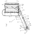
- FIG. 1 shows a side view of an embodiment of an agricultural machine according to the invention
- FIG. 2 shows a top view of the agricultural machine of FIG. 1 in transport position
- FIG. 3 shows a top view of the agricultural machine of FIG. 1 in an operative position
- FIG. 4 shows a top view of the agricultural machine of FIG. 1 in an alternative operative position.
- FIGS. 1 , 2 and 3 show an embodiment of an agricultural machine 1 , in particular a mower, according to the invention, designated as a whole by reference numeral 1 .
- the agricultural machine 1 is configured to be fastened with its front end to a (non-shown) tractor or other pulling vehicle in order to be moved in a customary direction of travel A.
- the agricultural machine 1 comprises a frame 2 which is supported by a number of wheels 3 .
- a mowing device 4 is suspended from the frame 2 .
- the mowing device 4 is movable with respect to the frame 2 , so that said mowing device 4 can be brought into different positions with respect to the frame 2 by means of the hydraulic lift cylinder 5 .
- the mowing device 4 will be placed in a relatively high position during transport, while the mowing device 4 will be placed near the ground for mowing a crop.
- Such mowing devices 4 are known per se and will not be set out here in further detail.
- the agricultural machine 1 is to be fastened to a tractor by means of a fastening device 6 .
- the fastening device 6 hingeably supports a first end 7 a of a drawbar 7 .
- the second end 7 b of the drawbar 7 is hingeably fastened to the frame 2 .
- the frame 2 and therewith the mowing device 4 can be pulled by the tractor by means of the drawbar 7 .
- a hydraulic cylinder 8 is provided between the frame 2 and the drawbar 7 .
- the drawbar 7 can be placed in different positions with respect to the frame 2 .
- the mowing device 4 will assume a different position with respect to the tractor.
- a telescopic drive shaft 9 for driving the mowing device 4 is provided between the fastening device 6 and the mowing device 4 .
- the telescopic drive shaft 9 comprises a first shaft part 10 and a second shaft part 11 .
- the first shaft part 10 comprises a first shaft end 9 a which is hingeably fastened to the fastening device 6 and which can be coupled to a drive of the tractor.
- the second shaft part 11 comprises a second shaft end 9 b which is hingeably fastened to a coupling 12 provided on the mowing device 4 .
- the coupling 12 is preferably a wide-angle coupling which allows the mowing device 4 to be driven at different orientations of the drive shaft 9 with respect to the coupling 12 .
- the first shaft part 10 comprises a cylindrical cavity in which the second shaft part 11 is enclosed so as to be shiftable in longitudinal direction.
- the second shaft part is flexible and/or is fastened with some clearance to the mowing device 4 in order to enable movements of the mowing device 4 .
- the first shaft part 10 and the second shaft part 11 may consist of a plurality of components which may possibly also have different orientations with respect to each other.
- a steering device 14 which is configured to direct the first shaft part 10 to the second shaft end 9 b , so that the first shaft part 10 and the second shaft part 11 remain located in the same plane, i.e. that the first shaft part 10 and the second shaft part 11 are in alignment with each other in a proper manner.
- the steering device 14 comprises a steering rod 15 which is fastened with a first steering rod end 15 a to an arm 16 , and with a second steering rod end 15 b to the frame 2 .
- the arm 16 is disposed on a support 17 of the first shaft part 10 and extends substantially perpendicular to the longitudinal direction of the drive shaft 9 .
- the steering rod 15 will adjust the orientation of the first shaft part 10 so that the latter remains directed to the second shaft end 9 b in such a manner that the first shaft part 10 and the second shaft part 11 remain located substantially in a vertical plane.
- the drive shaft 9 remains operative in different positions of the mowing device 4 with respect to the fastening device 6 , and the mowing device can be used in these different positions and during the displacement of the mowing devices between the different positions.
- the fastening point of the second end 7 b of the drawbar 7 is located near the rear side of the agricultural machine, which has a favourable effect on the stability of the machine.
- the steering device comprises a steering rod 15 and a steering yoke 18 .
- the steering yoke comprises a first yoke arm 18 a and a second yoke arm 18 b , and a hinge point 7 a between the two yoke arms.
- the steering yoke is hingeably fastened to the drawbar 7 .
- the first yoke arm 18 a is hingeably fastened to the support 17 of the first shaft part 10 and the second yoke arm 18 b is hingeably coupled to the first steering rod end 15 of the steering rod 15 .
- the second steering rod end 15 b is hingeably fastened to the frame 2 .
- steering device can also be applied in order to keep the first shaft part 10 directed to the second shaft end 9 b of the drive shaft 9 .
Abstract
Description
-
- a fastening device which is to be fastened to a pulling vehicle in order to move the agricultural machine in a customary direction of travel (A),
- a frame,
- an implement fastened to the frame,
- an elongate drawbar which has a first end that is hingeably fastened to the fastening device and a second end that is hingeably fastened to the frame, and
- an actuator which is provided between the frame and the drawbar, in order to move the frame between at least a transport position in which the frame is located at least partly behind the fastening device in the customary direction of travel and an operative position in which the frame is located laterally of the fastening device in the customary direction of travel,
characterized in that the agricultural machine comprises: - a telescopic drive shaft comprising a first shaft part which has a first shaft end of the telescopic drive shaft, and a second shaft part which is movable with respect to the first shaft part and which has a second shaft end of the telescopic drive shaft, wherein the first shaft end is connected to the fastening device and the second shaft end is connected to the implement, and
- a steering device which is configured to direct the first shaft part of the telescopic drive shaft substantially to the second shaft end of the telescopic drive shaft.
Claims (8)
Priority Applications (1)
| Application Number | Priority Date | Filing Date | Title |
|---|---|---|---|
| US14/022,251 US9125337B2 (en) | 2009-06-26 | 2013-09-10 | Agricultural machine movable between a lateral transport position and an operative position |
Applications Claiming Priority (5)
| Application Number | Priority Date | Filing Date | Title |
|---|---|---|---|
| NL1037078 | 2009-06-26 | ||
| NL1037078A NL1037078C2 (en) | 2009-06-26 | 2009-06-26 | AGRICULTURAL MACHINE. |
| PCT/NL2010/000089 WO2010151111A1 (en) | 2009-06-26 | 2010-05-26 | Agricultural machine |
| US13/330,706 US8555606B2 (en) | 2009-06-26 | 2011-12-20 | Agricultural machine movable between a lateral transport position and an operative position |
| US14/022,251 US9125337B2 (en) | 2009-06-26 | 2013-09-10 | Agricultural machine movable between a lateral transport position and an operative position |
Related Parent Applications (1)
| Application Number | Title | Priority Date | Filing Date |
|---|---|---|---|
| US13/330,706 Continuation US8555606B2 (en) | 2009-06-26 | 2011-12-20 | Agricultural machine movable between a lateral transport position and an operative position |
Publications (2)
| Publication Number | Publication Date |
|---|---|
| US20140007552A1 US20140007552A1 (en) | 2014-01-09 |
| US9125337B2 true US9125337B2 (en) | 2015-09-08 |
Family
ID=41667236
Family Applications (2)
| Application Number | Title | Priority Date | Filing Date |
|---|---|---|---|
| US13/330,706 Active US8555606B2 (en) | 2009-06-26 | 2011-12-20 | Agricultural machine movable between a lateral transport position and an operative position |
| US14/022,251 Expired - Fee Related US9125337B2 (en) | 2009-06-26 | 2013-09-10 | Agricultural machine movable between a lateral transport position and an operative position |
Family Applications Before (1)
| Application Number | Title | Priority Date | Filing Date |
|---|---|---|---|
| US13/330,706 Active US8555606B2 (en) | 2009-06-26 | 2011-12-20 | Agricultural machine movable between a lateral transport position and an operative position |
Country Status (5)
| Country | Link |
|---|---|
| US (2) | US8555606B2 (en) |
| EP (1) | EP2445330B1 (en) |
| DK (1) | DK2445330T3 (en) |
| NL (1) | NL1037078C2 (en) |
| WO (1) | WO2010151111A1 (en) |
Families Citing this family (4)
| Publication number | Priority date | Publication date | Assignee | Title |
|---|---|---|---|---|
| ITFO20130006A1 (en) * | 2013-10-22 | 2015-04-23 | Elvis Brighi | AGRICULTURAL TOOL FOR THE IMPLEMENTATION OF PACKAGED PLANTS |
| NL2011697C2 (en) * | 2013-10-29 | 2015-04-30 | Forage Innovations Bv | Agricultural vehicle adapted for curve driving. |
| KR20160000355A (en) * | 2014-06-24 | 2016-01-04 | 삼성전자주식회사 | Method of Inviting other Devices to Chat Room by Using Information on Access Point and Device therefor |
| US11144655B2 (en) * | 2018-05-03 | 2021-10-12 | Citrix Systems, Inc. | Control viewing access to documents in collaborative scenarios using facial recognition from webcams |
Citations (23)
| Publication number | Priority date | Publication date | Assignee | Title |
|---|---|---|---|---|
| US4392339A (en) * | 1980-11-26 | 1983-07-12 | Hesston Corporation | Crop windrowing machine having double windrow-forming attachment |
| US4418518A (en) * | 1982-05-03 | 1983-12-06 | Sperry Corporation | Mechanism for spring loading a transport lock |
| US4435948A (en) * | 1982-09-30 | 1984-03-13 | Sperry Corporation | Mechanism for pivoting windrow shields into a vertical transport position |
| US4558560A (en) * | 1984-09-19 | 1985-12-17 | Sperry Corporation | Pivot tongue harvester with lateral transport |
| EP0269166A2 (en) | 1986-11-12 | 1988-06-01 | C. van der Lely N.V. | A mowing machine |
| US4991383A (en) * | 1988-03-04 | 1991-02-12 | Kuhn S.A. | Agricultural harvesting machine movable into two positions |
| US5272859A (en) * | 1992-04-14 | 1993-12-28 | Hay & Forage Industries | Mechanical drive center pivot mower conditioner |
| US5522208A (en) * | 1993-11-23 | 1996-06-04 | Kuhn S.A. | Farm machine and connecting and transmission device therefor |
| US5566535A (en) * | 1995-05-09 | 1996-10-22 | Hay & Forage Industries | Remote header angle adjustment mechanism for swing-tongue harvesters |
| EP0800757A1 (en) | 1996-04-09 | 1997-10-15 | Kuhn S.A. | Agricultural machine with a pivoting connecting means to a tractor vehicle and a pivoting gearbox |
| FR2759531A1 (en) | 1997-02-14 | 1998-08-21 | Kuhn Sa | AGRICULTURAL CUTTING MACHINE COMPRISING AN IMPROVED SUSPENSION DEVICE OF THE CUTTING MECHANISM |
| US5964076A (en) | 1997-02-05 | 1999-10-12 | Gehl Company | Mower conditioner gear box steering device |
| US6003291A (en) | 1996-04-09 | 1999-12-21 | Kuhn, S.A. | Agriculture machine |
| US6044633A (en) | 1998-03-09 | 2000-04-04 | New Holland North America, Inc. | Control apparatus for rotatable gearbox on crop harvester |
| US6189306B1 (en) | 1998-02-10 | 2001-02-20 | Kuhn S.A. | Agricultural machine comprising a pivotable drawbar and transmission members comprising a coupling with universal joints |
| US6360516B1 (en) * | 2000-06-29 | 2002-03-26 | New Holland North America, Inc. | Two stage hydraulic tongue swing mechanism |
| US6662540B1 (en) | 2002-09-04 | 2003-12-16 | New Holland North America, Inc. | Method and apparatus for controlling pivotal movement of the tongue of a harvesting machine |
| US7047714B1 (en) | 2005-02-02 | 2006-05-23 | Deere & Company | Tongue swing cylinder arrangement for rotary side-pull mower-conditioner |
| US7207166B2 (en) | 2005-02-02 | 2007-04-24 | Deere & Company | Side-pull mower-conditioner tongue pivotably mounted to platform frame at location inboard of platform gearbox |
| DE202007015176U1 (en) | 2007-10-31 | 2009-03-12 | Alois Pöttinger Maschinenfabrik Gmbh | agricultural machinery |
| US7596935B2 (en) | 2007-10-30 | 2009-10-06 | Vermeer Manufacturing Company | Suspension system for a floating header on an agricultural implement |
| US7658056B2 (en) * | 2007-10-30 | 2010-02-09 | Vermeer Manufacturing Co. | System for folding an agricultural machine with a floating work tool |
| US20110219738A1 (en) | 2010-03-12 | 2011-09-15 | Thompson Kent L | Automatically Steered Gearboxes for an Implement with a Pivoting Tongue |
-
2009
- 2009-06-26 NL NL1037078A patent/NL1037078C2/en not_active IP Right Cessation
-
2010
- 2010-05-26 WO PCT/NL2010/000089 patent/WO2010151111A1/en active Application Filing
- 2010-05-26 DK DK10726338.6T patent/DK2445330T3/en active
- 2010-05-26 EP EP10726338.6A patent/EP2445330B1/en not_active Not-in-force
-
2011
- 2011-12-20 US US13/330,706 patent/US8555606B2/en active Active
-
2013
- 2013-09-10 US US14/022,251 patent/US9125337B2/en not_active Expired - Fee Related
Patent Citations (28)
| Publication number | Priority date | Publication date | Assignee | Title |
|---|---|---|---|---|
| US4392339A (en) * | 1980-11-26 | 1983-07-12 | Hesston Corporation | Crop windrowing machine having double windrow-forming attachment |
| US4418518A (en) * | 1982-05-03 | 1983-12-06 | Sperry Corporation | Mechanism for spring loading a transport lock |
| US4435948A (en) * | 1982-09-30 | 1984-03-13 | Sperry Corporation | Mechanism for pivoting windrow shields into a vertical transport position |
| US4558560A (en) * | 1984-09-19 | 1985-12-17 | Sperry Corporation | Pivot tongue harvester with lateral transport |
| EP0269166A2 (en) | 1986-11-12 | 1988-06-01 | C. van der Lely N.V. | A mowing machine |
| US4991383A (en) * | 1988-03-04 | 1991-02-12 | Kuhn S.A. | Agricultural harvesting machine movable into two positions |
| US5272859A (en) * | 1992-04-14 | 1993-12-28 | Hay & Forage Industries | Mechanical drive center pivot mower conditioner |
| US5522208A (en) * | 1993-11-23 | 1996-06-04 | Kuhn S.A. | Farm machine and connecting and transmission device therefor |
| US5566535A (en) * | 1995-05-09 | 1996-10-22 | Hay & Forage Industries | Remote header angle adjustment mechanism for swing-tongue harvesters |
| EP0800757A1 (en) | 1996-04-09 | 1997-10-15 | Kuhn S.A. | Agricultural machine with a pivoting connecting means to a tractor vehicle and a pivoting gearbox |
| US5901533A (en) | 1996-04-09 | 1999-05-11 | Kuhn, S.A. | Agricultural machine |
| US6003291A (en) | 1996-04-09 | 1999-12-21 | Kuhn, S.A. | Agriculture machine |
| US5964076A (en) | 1997-02-05 | 1999-10-12 | Gehl Company | Mower conditioner gear box steering device |
| US6182427B1 (en) | 1997-02-05 | 2001-02-06 | Gehl Company | Driveshaft/bearing gearbox steering arrangement |
| FR2759531A1 (en) | 1997-02-14 | 1998-08-21 | Kuhn Sa | AGRICULTURAL CUTTING MACHINE COMPRISING AN IMPROVED SUSPENSION DEVICE OF THE CUTTING MECHANISM |
| US6055800A (en) | 1997-02-14 | 2000-05-02 | Kuhn S.A. | Agricultural cutting machine comprising an improved suspension device for the cutting mechanism |
| US6189306B1 (en) | 1998-02-10 | 2001-02-20 | Kuhn S.A. | Agricultural machine comprising a pivotable drawbar and transmission members comprising a coupling with universal joints |
| US6044633A (en) | 1998-03-09 | 2000-04-04 | New Holland North America, Inc. | Control apparatus for rotatable gearbox on crop harvester |
| US6360516B1 (en) * | 2000-06-29 | 2002-03-26 | New Holland North America, Inc. | Two stage hydraulic tongue swing mechanism |
| US6662540B1 (en) | 2002-09-04 | 2003-12-16 | New Holland North America, Inc. | Method and apparatus for controlling pivotal movement of the tongue of a harvesting machine |
| US7047714B1 (en) | 2005-02-02 | 2006-05-23 | Deere & Company | Tongue swing cylinder arrangement for rotary side-pull mower-conditioner |
| US7207166B2 (en) | 2005-02-02 | 2007-04-24 | Deere & Company | Side-pull mower-conditioner tongue pivotably mounted to platform frame at location inboard of platform gearbox |
| US7596935B2 (en) | 2007-10-30 | 2009-10-06 | Vermeer Manufacturing Company | Suspension system for a floating header on an agricultural implement |
| US7658056B2 (en) * | 2007-10-30 | 2010-02-09 | Vermeer Manufacturing Co. | System for folding an agricultural machine with a floating work tool |
| US7966794B2 (en) | 2007-10-30 | 2011-06-28 | Vermeer Manufacturing Company | Method for a drive system of an agricultural machine with a floating work tool |
| DE202007015176U1 (en) | 2007-10-31 | 2009-03-12 | Alois Pöttinger Maschinenfabrik Gmbh | agricultural machinery |
| EP2055172A2 (en) * | 2007-10-31 | 2009-05-06 | Alois Pöttinger Maschinenfabrik GmbH | Agricultural machine |
| US20110219738A1 (en) | 2010-03-12 | 2011-09-15 | Thompson Kent L | Automatically Steered Gearboxes for an Implement with a Pivoting Tongue |
Non-Patent Citations (2)
| Title |
|---|
| International Preliminary Report on Patentability of PCT/NL2010/000089 issued on Jan. 4, 2012. |
| International Search Report of PCT/NL2010/000089 issued on Oct. 28, 2010. |
Also Published As
| Publication number | Publication date |
|---|---|
| EP2445330B1 (en) | 2013-05-15 |
| WO2010151111A1 (en) | 2010-12-29 |
| US8555606B2 (en) | 2013-10-15 |
| US20120085075A1 (en) | 2012-04-12 |
| NL1037078C2 (en) | 2010-12-28 |
| US20140007552A1 (en) | 2014-01-09 |
| DK2445330T3 (en) | 2013-07-22 |
| EP2445330A1 (en) | 2012-05-02 |
Similar Documents
| Publication | Publication Date | Title |
|---|---|---|
| US9526204B2 (en) | Lateral transport wheel assembly | |
| US7861795B2 (en) | Implement transport | |
| US6907719B2 (en) | Agricultural implement comprising a transporting device | |
| AU2014372572B2 (en) | Agricultural machine | |
| US8770309B2 (en) | Wide swath folding tool bar assembly | |
| US9125337B2 (en) | Agricultural machine movable between a lateral transport position and an operative position | |
| US7971886B2 (en) | Steering for towed implements | |
| ATE540570T1 (en) | CONNECTION BETWEEN TRACTOR AND TOWING ARM OF A TOWED HARVESTING MACHINE | |
| US7712295B2 (en) | Agricultural machine comprising a motor vehicle and several working units intended to cut plant products | |
| CA2323988C (en) | Self-propelled agricultural vehicle | |
| CA2890534C (en) | Device for harvesting long agricultural products and agricultural self-propelled unit for harvesting agricultural products comprising the device | |
| US7025008B2 (en) | Agricultural implement hitch | |
| EP3018990B1 (en) | Work vehicle | |
| US6644001B2 (en) | Implement combination | |
| US6481192B1 (en) | Steering tube for pivotally rotating a hay harvester gearbox | |
| EP1095553A1 (en) | Drive mechanism for the trituration device of a shredder | |
| EP0900520B1 (en) | A draw agricultural machine | |
| SU1583014A1 (en) | Tractor-drawn machine for harvesting green stock of agricultural plants |
Legal Events
| Date | Code | Title | Description |
|---|---|---|---|
| FEPP | Fee payment procedure |
Free format text: PAYOR NUMBER ASSIGNED (ORIGINAL EVENT CODE: ASPN); ENTITY STATUS OF PATENT OWNER: LARGE ENTITY |
|
| ZAAA | Notice of allowance and fees due |
Free format text: ORIGINAL CODE: NOA |
|
| ZAAB | Notice of allowance mailed |
Free format text: ORIGINAL CODE: MN/=. |
|
| STCF | Information on status: patent grant |
Free format text: PATENTED CASE |
|
| MAFP | Maintenance fee payment |
Free format text: PAYMENT OF MAINTENANCE FEE, 4TH YEAR, LARGE ENTITY (ORIGINAL EVENT CODE: M1551); ENTITY STATUS OF PATENT OWNER: LARGE ENTITY Year of fee payment: 4 |
|
| FEPP | Fee payment procedure |
Free format text: MAINTENANCE FEE REMINDER MAILED (ORIGINAL EVENT CODE: REM.); ENTITY STATUS OF PATENT OWNER: LARGE ENTITY |
|
| LAPS | Lapse for failure to pay maintenance fees |
Free format text: PATENT EXPIRED FOR FAILURE TO PAY MAINTENANCE FEES (ORIGINAL EVENT CODE: EXP.); ENTITY STATUS OF PATENT OWNER: LARGE ENTITY |
|
| STCH | Information on status: patent discontinuation |
Free format text: PATENT EXPIRED DUE TO NONPAYMENT OF MAINTENANCE FEES UNDER 37 CFR 1.362 |
|
| FP | Lapsed due to failure to pay maintenance fee |
Effective date: 20230908 |