US9124499B2 - Frame transmission system - Google Patents
Frame transmission system Download PDFInfo
- Publication number
- US9124499B2 US9124499B2 US13/747,382 US201313747382A US9124499B2 US 9124499 B2 US9124499 B2 US 9124499B2 US 201313747382 A US201313747382 A US 201313747382A US 9124499 B2 US9124499 B2 US 9124499B2
- Authority
- US
- United States
- Prior art keywords
- frame
- length
- transfer
- header
- frames
- Prior art date
- Legal status (The legal status is an assumption and is not a legal conclusion. Google has not performed a legal analysis and makes no representation as to the accuracy of the status listed.)
- Expired - Fee Related, expires
Links
Images


Classifications
-
- H—ELECTRICITY
- H04—ELECTRIC COMMUNICATION TECHNIQUE
- H04L—TRANSMISSION OF DIGITAL INFORMATION, e.g. TELEGRAPHIC COMMUNICATION
- H04L41/00—Arrangements for maintenance, administration or management of data switching networks, e.g. of packet switching networks
- H04L41/08—Configuration management of networks or network elements
- H04L41/0896—Bandwidth or capacity management, i.e. automatically increasing or decreasing capacities
-
- H—ELECTRICITY
- H04—ELECTRIC COMMUNICATION TECHNIQUE
- H04L—TRANSMISSION OF DIGITAL INFORMATION, e.g. TELEGRAPHIC COMMUNICATION
- H04L1/00—Arrangements for detecting or preventing errors in the information received
- H04L1/0001—Systems modifying transmission characteristics according to link quality, e.g. power backoff
- H04L1/0006—Systems modifying transmission characteristics according to link quality, e.g. power backoff by adapting the transmission format
- H04L1/0007—Systems modifying transmission characteristics according to link quality, e.g. power backoff by adapting the transmission format by modifying the frame length
-
- H—ELECTRICITY
- H04—ELECTRIC COMMUNICATION TECHNIQUE
- H04L—TRANSMISSION OF DIGITAL INFORMATION, e.g. TELEGRAPHIC COMMUNICATION
- H04L1/00—Arrangements for detecting or preventing errors in the information received
- H04L1/004—Arrangements for detecting or preventing errors in the information received by using forward error control
- H04L1/0056—Systems characterized by the type of code used
- H04L1/0061—Error detection codes
-
- H—ELECTRICITY
- H04—ELECTRIC COMMUNICATION TECHNIQUE
- H04L—TRANSMISSION OF DIGITAL INFORMATION, e.g. TELEGRAPHIC COMMUNICATION
- H04L1/00—Arrangements for detecting or preventing errors in the information received
- H04L1/0078—Avoidance of errors by organising the transmitted data in a format specifically designed to deal with errors, e.g. location
- H04L1/0083—Formatting with frames or packets; Protocol or part of protocol for error control
-
- H—ELECTRICITY
- H04—ELECTRIC COMMUNICATION TECHNIQUE
- H04L—TRANSMISSION OF DIGITAL INFORMATION, e.g. TELEGRAPHIC COMMUNICATION
- H04L47/00—Traffic control in data switching networks
- H04L47/10—Flow control; Congestion control
- H04L47/36—Flow control; Congestion control by determining packet size, e.g. maximum transfer unit [MTU]
Definitions
- the present invention relates to a frame transmission system that transmits variable-length frames such as IP frames or Ethernet frames.
- the SDH/SONET technology is a technique where data is transmitted and received at fixed intervals using fixed-length frames, so that variation in transmission delay is small.
- the Ethernet technology is a technique where data is transmitted and received intermittently using variable-length frames, so that the variation in transmission delay tends to be larger than that in the SDH/SONET technology.
- the Ethernet technology suffers the variation in transmission delay caused by the use of variable-length frames.
- variable-length frames such as Ethernet frames
- variable-length frame is fragmented into a plurality of fixed-length frames. That is, a long frame is fragmented into short frames for use with data transfer, so that the variation in wait time for a process in the frame junction is reduced and therefore the variation in transmission delay can be suppressed.
- a header carrying the information required to restore the original frame (this header will be referred to as “reproduction header” also) is appended to each fragmented frame.
- a rate of bandwidth increase due to the appending of the header is expressed by (frame length+header length)/(frame length).
- the rate of bandwidth increase becomes maximum at the minimum frame whose frame length is 64 bytes (e.g., the rate of bandwidth increase being (64+4)/64 ⁇ 1.06 where the header length is 4 bytes).
- the bandwidth must be secured in consideration of a case where the maximum number of such minimum frames is inputted, so that the bandwidth utilization efficiency drops.
- the present invention has been made in view of the foregoing circumstances, and a purpose thereof is to provide a technology capable of suppressing the rate of bandwidth increase in a frame transmission system that fragments variable-length frames and transmits the thus fragmented frames.
- a frame transmission system includes: a frame transmitter including: a frame fragmentation unit configured to fragment an input frame so as to output transfer frames when the length of the input frame exceeds a predetermined fragmentation reference frame length and configured not to fragment the input frame so as to output the input frame as a transfer frame when the length of the input frame is less than or equal to the fragmentation reference frame length; and a reproduction header appending unit configured to append a reproduction header to the transfer frame outputted from the frame fragmentation unit, the reproduction header being required when the transfer frames are reproduced at a receiving side; and a frame receiver including a frame reassembling unit for reproducing the original frame from the transfer frames received from the frame transmitter.
- the reproduction header appending unit varies the header length of the reproduction header to be appended to the transfer frame, according to the length of the input frame.
- the reproduction header appending unit may not append the reproduction header to the transfer frames; when the length of the input frame is greater than 1 ⁇ 2 of the fragmentation reference frame length and less than or equal to the fragmentation reference frame length, the reproduction header appending unit may append a first reproduction header having a first predetermined header length to the transfer frames; and when the length of the input frame is greater than the fragmentation reference frame length, the reproduction header appending unit may append a second reproduction header having a second predetermined header length, which is longer than the first predetermined header length, to the transfer frames.
- the frame fragmentation unit may fragment the input frame in a manner such that the length of the transfer frame becomes greater than 1 ⁇ 2 of the fragmentation reference frame length.
- the frame reassembling unit may identify whether or not the reproduction header is appended to the transfer frame, based on the frame length of the transfer frame received.
- the first reproduction frame may include information indicating that the transfer frame is not a fragmented frame
- the second reproduction frame may include information indicating that the transfer frame is a fragmented frame
- the frame reassembling unit may identify that the reproduction header is the first reproduction header or the second reproduction header, based on the information, contained in the reproduction header appended to the received transfer frame, indicating whether the transfer frame is a fragmented frame or not.
- the second reproduction header may further contain a frame identification number and a frame sequence number.
- the frame reassembling unit may discard said transfer frames.
- the frame reassembling unit may include a buffer used for a frame reassembling process, and the buffer may be configured to set an output priority after the frame reassembling process has been completed.
- FIG. 1 shows a frame transmission system according to an embodiment of the present invention
- FIG. 2 shows a structure of a frame transmitter
- FIG. 3 shows a structure of the frame receiver
- FIG. 4 shows a list of frame fragmentation processes according to the length of input frames
- FIGS. 5A to 5C are diagrams for explaining the frame fragmentation processes according to the length of input frames.
- FIG. 6 is a flowchart showing a frame fragmentation process
- FIG. 7 is a diagram for explaining a format of first reproduction header
- FIG. 8 is a diagram for explaining a format of first reproduction header
- FIG. 9 is a diagram for explaining a format of second reproduction header
- FIG. 10 is a diagram for explaining a format of second reproduction header
- FIGS. 11A and 11B are each a flowchart showing a frame reassembling process in a frame receiver
- FIG. 12 is a flowchart showing a frame reassembling process
- FIG. 13 shows a list of conditions under which a frame is discarded in a frame reassembling process
- FIG. 14 is a diagram for explaining an operation in a reassembly buffer clearing process shown in the item 5 of FIG. 13 ;
- FIG. 15 shows a structure of a buffer for use in reassembly
- FIG. 16 is a diagram for explaining problems caused when no output priority is given after reassembly.
- FIG. 1 shows a frame transmission system 100 according to an embodiment of the present invention.
- the frame transmission system 100 shown in FIG. 1 is a transmission system that transmits and receives Ethernet frames.
- the frame transmission system 100 includes a frame transmit/receive device 11 A and a frame transmit/receive device 11 B.
- the frame transmit/receive devices 11 A and 11 B each includes a frame transmitter 10 , a frame receiver 12 , and a monitoring control unit 13 .
- the frame transmission system 100 is capable of performing two-way frame transmission. That is, the frame transmission system 100 can transmit frames from the frame transmitter 10 of the frame transmit/receive device 11 A to the frame receiver 12 of the frame transmit/receive device 11 B and can also transmit frames from the frame transmitter 10 of the frame transmit/receive device 11 B to the frame receiver 12 of the frame transmit/receive device 11 A.
- the monitoring control unit 13 which is comprised of a CPU, a ROM, a RAM, a communication interface and so forth, monitors and controls the components inside the frame transmit/receive device 11 and communicates with other devices.
- Frames are inputted to the frame transmitter 10 from a client. Since these frames are Ethernet frames, each Ethernet frame has the frame length of 64 to 9600 bytes. Following an inputted frame, a frame check sequence (FCS) for use in detecting error is appended. It is assumed in the present embodiment that FCS is 4 byte long.
- the frame transmitter 10 fragments an input frame fed from the client into a plurality of fragmented frames, which are used to transfer each input frame (these fragmented frames will be referred to as “transfer frames” also), and then transfers the thus fragmented frames to the frame receiver 12 .
- a transfer header carrying the information about a transfer destination and a reproduction header carrying the information required when a fragmented frame is reassembled and reproduced at the frame receiver 12 are appended to each transfer frame.
- the transfer header carries the information such as a destination address (DA), a source address (SA) and the type.
- the transfer frame transmitted from the frame transmitter 10 is received by the frame receiver 12 .
- the transfer frame may pass through a not-shown relay device while it is transmitted from the frame transmitter 10 up to the frame receiver 12 .
- the frame receiver 12 reassembles and reproduces a plurality of fragmented frames received thereby into an original frame and then outputs the original frame to the client.
- FIG. 2 shows a structure of the frame transmitter 10 .
- the frame transmitter 10 includes a frame fragmentation unit 16 , a reproduction header appending unit 18 , and a transfer processing unit 20 .
- the frame fragmentation unit 16 receives frames from the client and generates transfer frames.
- the frame fragmentation unit 16 fragments an input frame according to the length of the input frame (frame length) inputted from the client. More specifically, if the input frame is greater than a predetermined fragmentation reference frame length FL, the frame fragmentation unit 16 will fragment the input frame so as to generate a plurality of transfer frames. If, on the other hand, the frame length is less than or equal to the fragmentation reference frame length FL, the frame fragmentation unit 16 will not fragment this input frame and then output it as a transfer frame.
- the length of a frame ranges from 64 to 9600 bytes.
- the frame fragmentation unit 16 does not fragment the input frame, whose length ranges from 64 to FL bytes, and then outputs it as it is, and fragments the input frame, whose length ranges from (FL+1) to 9600 bytes, and then outputs the fragmented frames.
- the reproduction header appending unit 18 appends a reproduction header to the transfer frame outputted from the frame fragmentation unit 16 . Though its detail will be discussed later, the reproduction header varies the header length of the reproduction header to be appended to the transfer frame, according to the length of the input frame inputted to the frame fragmentation unit 16 .
- the transfer processing unit 20 appends a transfer header to a transfer frame outputted from the reproduction header appending unit 18 and then transmits the transfer frame to the frame receiver 12 .
- FIG. 3 shows a structure of the frame receiver 12 .
- the frame receiver 12 includes a receiving processing unit 22 and a frame reassembling unit 26 .
- the receiving processing unit 22 receives the transfer frames from the frame transmitter 10 .
- the receiving processing unit 22 removes the transfer head from the transfer frame and then outputs the transfer frame without the transfer header appended thereto to the frame reassembling unit 24 .
- the frame reassembling unit 24 restores and reproduces the original frame from the transfer frames inputted from the receiving processing unit 22 .
- FIG. 4 shows a list of frame fragmentation processes according to the length of input frames.
- FIGS. 5A to 5C are diagrams for explaining the frame fragmentation processes according to the length of input frames.
- the frame fragmentation process differs depending on the length of each input frame (input frame length) inputted to the frame fragmentation unit 16 .
- the frame fragmentation unit 16 does not fragment the input frame and then outputs it directly as a transfer frame.
- the reproduction header appending unit 18 outputs the transfer frame without appending the reproduction header thereto.
- the frame fragmentation unit 16 does not fragment the input frame and then outputs directly it as a transfer frame.
- the reproduction header appending unit 18 appends a first reproduction header, having a first header length, to the transfer frame.
- the frame fragmentation unit 16 fragments an input frame and then outputs a plurality of transfer frames.
- the reproduction header appending unit 18 appends a second reproduction header, having a second header length, to each transfer frame.
- the second header length is longer than the first header length.
- the second header is 4 byte long.
- “dummy” is appended to the end of each fragmented frame except for the last transfer frame.
- the frame transmission system 100 according to the present embodiment is a system that handles an processes Ethernet frames, and FCS is appended to each transfer frame. The “dummy” is appended for the purpose of ensuring the area to be occupied by FCS later. The “dummy” will be converted to FCS by the transfer processing unit 20 disposed at a subsequent stage.
- the reproduction header appending unit 18 varies the header length of a reproduction header to be appended to a transfer frame, according to the length of an input frame inputted to the frame fragmentation unit 16 . If no reproduction header is appended, this can be thought of as the header length being equal to 0 byte. In this manner, the length of the reproduction header is varied as appropriate, so that the rate of bandwidth increase can be significantly reduced as compared with the cases where the reproduction header appending unit 18 appends the reproduction headers to the transfer frames regardless of whether the fragmentation process is involved or not.
- FIG. 6 is a flowchart showing a frame fragmentation process. If the length of an input frame inputted to the frame fragmentation unit 16 exceeds the fragmentation reference frame length FL, the frame fragmentation process shown in the flowchart of FIG. 6 will be performed.
- the frame fragmentation unit 16 stores input frames, which are to be fragmented, in a frame buffer (S 10 ).
- the frame buffer may be of a store-and-forward switching method or cut-through switching method.
- the frame buffer may be of a type where although the processing starts after the entire frames have been buffered, a certain delay is given regardless of the byte length of frames.
- the buffer implementing the store-and-forward switching method is used, a buffer size is selectable efficiently. That is, the buffer size is smaller for a shorter frame, whereas a larger buffer is used for a longer frame. In this manner, the store-and-forward type buffer is advantageous in that the information concerning the frame end can also be referenced.
- the cut-through type buffer is used, it is only necessary that the buffer size is equal to that corresponding to the reproduction headers only. Further, the cut-through type buffer is advantageous in that the delay is suppressed to the minimum and the delay variation does not occur.
- the frame buffer of a type where the processing starts after the entire frames have been buffered but a certain delay is given regardless of the byte length of frames is used to suppress the delay variation in the store-and-forward switching.
- This type of buffer is advantageous in that the delay variation is suppressed.
- the frame fragmentation unit 16 determines if the length of frames remaining in the frame buffer (hereinafter referred to as “remaining frame length” also) is less than twice the fragmentation reference frame length FL (S 12 ). If the remaining frame length is greater than or equal to FL ⁇ 2 (No of S 12 ), the frame fragmentation unit 16 will extract FL bytes from the frame buffer (S 14 ) and append “Dummy” to the extracted FL-byte frame (S 16 ). As already mentioned, the “dummy” is appended in order to ensure the area to be occupied by FCS later. The dummy is not necessarily appended at the stage of Step S 16 as shown in FIG. 6 but may be appended in a process subsequent to Step S 16 .
- Step S 12 the procedure returns to Step S 12 , and Steps S 12 to S 16 are repeated. If, in Step S 12 , the remaining frame becomes smaller than FL ⁇ 2 (Yes of S 12 ), the frame fragmentation unit 16 will extract [the remaining frame length]/2 bytes from the frame buffer (S 18 ) and append “Dummy” to the extracted frame (S 20 ). If the frame length is not divisible by 2, the decimal places will be rounded up.
- the frame fragmentation unit 16 extracts the remaining frame from the frame buffer (S 22 ). At this time, the frame remaining in the frame buffer is 0 byte long. The frame fragmentation unit 16 appends FCS to the extracted frame so as to be outputted. The FCS appended this time may be the same FCS as that appended in the first place.
- Step S 12 of the flowchart shown in FIG. 6 it is determined whether or not the remaining frame length is smaller than twice the fragmentation reference frame length FL, and the remaining frame will be fragmented into half if the remaining frame length is smaller than FL ⁇ 2.
- the input frames are fragmented so that each length of all transfer frames is greater than 1 ⁇ 2 of the fragmentation reference frame length FL.
- each transfer frame can be converted to a frame, suited to an Ethernet format, whose length is greater than and equal to 64 bytes.
- the frame receiver 12 determines whether the transfer frame is fragmented or not, based on the length of the transfer frame. The length of the fragmented transfer frame is reliably made greater than FL/2, so that whether or not the transfer frame is fragmented can be suitably determined by the frame receiver 12 .
- FIG. 7 is a diagram for explaining a format of first reproduction header.
- the length of the first reproduction header (first header length) is 1 byte. 4 bits in this 1 byte are used as a fragment FLAG and the rest of 4 bits are used as “reserved”.
- FIG. 8 is a diagram for explaining a format of first reproduction header.
- fragment FLAG[3] indicates whether a frame is fragmented or not. If fragment FLAG[3] is “0”, this will indicate that the frame is not fragmented. If fragment FLAG[3] is “1”, this will indicate that the frame is fragmented.
- fragment FLAG[2:0] indicates where a frame after fragmentation is located.
- the fragment FLAG in the first reproduction header can only be a flag indicating the beginning of a frame, such a format as fragment FLAG[2:0] is used because the format is shared with the 4 bytes second reproduction header.
- FIG. 9 is a diagram for explaining a format of second reproduction header.
- the length of the second reproduction header (second header length) is 4 bytes.
- the second reproduction header has regions for an ID and a fragment sequence number.
- FIG. 10 is a diagram for explaining a format of second reproduction header.
- the ID is an identification number indicating the frame number of a frame before fragmentation. Appending the IDs can reduce the probability that frames will be erroneously reassembled in a frame reassembling process. In this frame reassembly processing, only transfer frames having the same IDs are reassembled. The larger the number of bits is for an ID, faulty reassembly can be further reduced.
- the fragment sequence numbers are information indicating that a frame associated with a given fragment sequence number belongs to which one of a plurality of transfer frames fragmented from an original frame. Having the fragment sequence numbers allows the transfer frames to be reassembled in the correct order even if the order of the transfer frames is reversed while the transfer frames pass through a communication path. Note that the fragment sequence numbers may be used to detect the frame reassembly error where frames are not reassembled in the correct sequence.
- FIGS. 11A and 11B are each a flowchart showing a frame reassembling process in the frame receiver 12 .
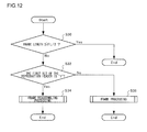
- FIG. 12 is a flowchart showing a frame reassembling process.
- the frame reassembling unit 24 determines whether the frame length of a received transfer frame is less than FL/2 or not (S 30 ).
- the frame reassembling unit 24 first verifies the frame length of the transfer frame. If the frame length thereof is less than or equal to FL/2 (Yes of S 30 ), the frame reassembling unit 24 will determine that no reproduction header is appended. In this case, no frame reassembling processing needs to be carried out and therefore the transfer header is directly outputted.
- the frame reassembling unit 24 will determine that a reproduction header is appended and then verify the first bit of the first byte of the reproduction header (i.e., fragment FLAG[3]). If fragment FLAG[3] is “0” (No of S 32 ), the frame reassembling unit 24 will determine that the transfer frame is not fragmented and then remove the reproduction header (first reproduction header) appended thereto (S 36 ).
- the frame reassembling unit 24 will determine that the transfer frame is a fragmented frame and then carry out the frame reassembling processing using the information such as the ID assigned to the reproduction header appended to the transfer frame and a fragment sequence number (S 34 ).
- the purpose of using two different reproduction headers is as follows. That is, the purpose thereof is to reliably distinguish between the case where the transfer frame is a fragmented frame and the case where it is not fragmented. If the first reproduction header is not used but whether or not the transfer frame is a fragment frame is to be determined solely based on the frame length of the transfer frame, there may be cases where the distinction cannot be made therebetween.
- the fragmentation reference frame length FL is set to 1000 bytes and a 600-byte transfer frame is received by the frame reassembling unit 24 .
- the frame reassembling unit 24 cannot make a distinction, as to whether or not the 600-bytes transfer frame is fragmented, by solely verifying the length of the transfer frame.
- appending the 4-byte second reproduction header to the 600-byte transfer frame which is not fragmented is not desirable from a viewpoint of the rate of bandwidth increase.
- the first reproduction header which is shorter than the second reproduction header, is appended to the 600-byte transfer frame that is not fragmented, whereas the second reproduction header is appended to the 600-byte transfer frames that are fragmented.
- FIG. 13 shows a list of conditions under which a frame/frames is/are discarded in the frame reassembling process.
- the frame is discarded when the reassembling process cannot be completed. If no frames is discarded, frames that fail to be reassembled completely will remain unused and unprocessed in a reassembly buffer. Thus properly discarding the frames will improve the rate of bandwidth increase in the reassembly buffer.
- FIG. 14 is a diagram for explaining an operation in the reassembly buffer clearing process shown in the item 5 of FIG. 13 .
- An operation performed to clear the assembly buffer (hereinafter referred to as “reassembly buffer clearing process” also) is required to effectively use the reassembly buffer.
- a trigger pulse used to trigger the clearing of the reassembly buffer is generated by hardware independently or is given from software at regular intervals (see “reassemble-frame-discard pulses in FIG. 14 ). If this reassemble-frame-discard pulse is used as a trigger and if not a single frame has arrived during a period of time from the occurrence of the previous pulse leading up to the present, the frame(s) will be discarded.
- FIG. 15 shows a structure of a buffer for use in reassembly. Since, for example, there are various waiting times occurring among frames in a system, the time intervals between which the transfer frames arrive at the frame receiver 12 are not equal. Thus, the transfer frames need to wait in the reassembly buffer before the reassembling processing has been completed. Accordingly, the buffer for use in reassembly is configured such that frames having a maximum frame length can be buffered therein. As shown in FIG. 15 , the transfer frames, which have been transmitted from the previous processing, are accumulated and saved in their respective buffers provided for the respective output flows. Each of the respective buffers for the respective output flows is configured such that an output priority can be set after the reassembly has been completed. In this example, the output priority is set to two levels, which are a “high” priority and a “normal” priority but a plurality of priority levels more than two levels may also be set.
- FIG. 16 is a diagram for explaining problems caused when no output priority is given after reassembly.
- a processor or the like capable of processing a large volume of frames is not configured in a manner that permits processing a plurality of processes in parallel. Instead, the processor or the like is generally so configured as to accelerate the processing and process a plurality of tasks serially. If the processor is not configured such that a plurality of processes is processed serially, a predetermined number of external memories will be required to realize a predetermined number of tasks in parallel when the processor interfaces with the external memories or the like. And this is not possibly practically and this is why the processor or the like is generally so configured as to process a plurality of tasks serially.
- FIG. 16 a description is given using a structure where a buffer is provided for each port. And through those buffers, frames, which are processed from right to left in a serial manner of 10 Gbps, undergo the reassembly processing by the use of the buffers provided for the respective ports, and then the frames are restored in a serial manner of 10 Gbps.
- the frame transmission system be configured as follows. That is, the priority level is set for each buffer. And if both the reassembly processing of frames having a high priority and the reassembly processing of those having a lower priority have been completed simultaneously, those having a higher priority will be outputted first.
Abstract
Description
Claims (8)
Applications Claiming Priority (2)
| Application Number | Priority Date | Filing Date | Title |
|---|---|---|---|
| JP2012011194A JP5808261B2 (en) | 2012-01-23 | 2012-01-23 | Frame transmission system |
| JP2012-011194 | 2012-01-23 |
Publications (2)
| Publication Number | Publication Date |
|---|---|
| US20130188654A1 US20130188654A1 (en) | 2013-07-25 |
| US9124499B2 true US9124499B2 (en) | 2015-09-01 |
Family
ID=47843684
Family Applications (1)
| Application Number | Title | Priority Date | Filing Date |
|---|---|---|---|
| US13/747,382 Expired - Fee Related US9124499B2 (en) | 2012-01-23 | 2013-01-22 | Frame transmission system |
Country Status (3)
| Country | Link |
|---|---|
| US (1) | US9124499B2 (en) |
| JP (1) | JP5808261B2 (en) |
| GB (1) | GB2500090B8 (en) |
Families Citing this family (3)
| Publication number | Priority date | Publication date | Assignee | Title |
|---|---|---|---|---|
| GB2533531A (en) * | 2013-09-13 | 2016-06-22 | Smg Holdings-Anova Tech Llc | Self-healing data transmission system to achieve lower latency |
| JP6813637B1 (en) * | 2019-08-08 | 2021-01-13 | Necプラットフォームズ株式会社 | Transmission device and transmission method |
| EP4040735A4 (en) | 2019-10-01 | 2023-10-18 | Hitachi Astemo, Ltd. | Vehicle control device and data transfer control method |
Citations (13)
| Publication number | Priority date | Publication date | Assignee | Title |
|---|---|---|---|---|
| US5956344A (en) * | 1997-02-03 | 1999-09-21 | Siemens Information And Communication Networks, Inc. | Interprocessor communications in an ATM environment |
| US6819658B1 (en) * | 1997-07-15 | 2004-11-16 | Comsat Corporation | Method and apparatus for segmentation, reassembly and inverse multiplexing of packets and ATM cells over satellite/wireless networks |
| JP2006074726A (en) | 2004-08-03 | 2006-03-16 | Fujitsu Ltd | Processing method of fragmented packet and packet transfer equipment employing the same |
| USRE39454E1 (en) * | 1987-03-17 | 2007-01-02 | Qpsx Communications Pty. Ltd. | Transfer of messages in a multiplexed system |
| JP2007267051A (en) | 2006-03-29 | 2007-10-11 | Nec Engineering Ltd | Packet receiving circuit |
| JP2007288491A (en) | 2006-04-17 | 2007-11-01 | Nippon Telegr & Teleph Corp <Ntt> | Dividing circuit of frame, and transmission system and method using dividing circuit |
| US20080037547A1 (en) * | 2004-10-22 | 2008-02-14 | Electronics And Telecommunications Research Institute | Method for segmenting and reassembling packet based on tree structure, and method for transmitting/receiving packet using the same |
| US20090201948A1 (en) * | 2008-02-13 | 2009-08-13 | Qualcomm Incorporated | Methods and apparatus for formatting headers in a communication frame |
| US20100074178A1 (en) * | 2006-12-22 | 2010-03-25 | Anna Larmo | Method for Indication of Consecutive Data Units in a RAN |
| US20100135495A1 (en) * | 2008-09-05 | 2010-06-03 | Hua Mary Chion | Mac layer packet data units for wireless communications |
| US20100322249A1 (en) * | 2009-06-23 | 2010-12-23 | Juniper Networks, Inc. | Discovering path maximum transmission unit size |
| JP2011160371A (en) | 2010-02-04 | 2011-08-18 | Fujitsu Telecom Networks Ltd | Communication control device |
| US20110211591A1 (en) * | 2010-02-26 | 2011-09-01 | Steven Traub | Reassembly of mini-packets in a buffer |
-
2012
- 2012-01-23 JP JP2012011194A patent/JP5808261B2/en not_active Expired - Fee Related
-
2013
- 2013-01-21 GB GB201301078A patent/GB2500090B8/en not_active Expired - Fee Related
- 2013-01-22 US US13/747,382 patent/US9124499B2/en not_active Expired - Fee Related
Patent Citations (13)
| Publication number | Priority date | Publication date | Assignee | Title |
|---|---|---|---|---|
| USRE39454E1 (en) * | 1987-03-17 | 2007-01-02 | Qpsx Communications Pty. Ltd. | Transfer of messages in a multiplexed system |
| US5956344A (en) * | 1997-02-03 | 1999-09-21 | Siemens Information And Communication Networks, Inc. | Interprocessor communications in an ATM environment |
| US6819658B1 (en) * | 1997-07-15 | 2004-11-16 | Comsat Corporation | Method and apparatus for segmentation, reassembly and inverse multiplexing of packets and ATM cells over satellite/wireless networks |
| JP2006074726A (en) | 2004-08-03 | 2006-03-16 | Fujitsu Ltd | Processing method of fragmented packet and packet transfer equipment employing the same |
| US20080037547A1 (en) * | 2004-10-22 | 2008-02-14 | Electronics And Telecommunications Research Institute | Method for segmenting and reassembling packet based on tree structure, and method for transmitting/receiving packet using the same |
| JP2007267051A (en) | 2006-03-29 | 2007-10-11 | Nec Engineering Ltd | Packet receiving circuit |
| JP2007288491A (en) | 2006-04-17 | 2007-11-01 | Nippon Telegr & Teleph Corp <Ntt> | Dividing circuit of frame, and transmission system and method using dividing circuit |
| US20100074178A1 (en) * | 2006-12-22 | 2010-03-25 | Anna Larmo | Method for Indication of Consecutive Data Units in a RAN |
| US20090201948A1 (en) * | 2008-02-13 | 2009-08-13 | Qualcomm Incorporated | Methods and apparatus for formatting headers in a communication frame |
| US20100135495A1 (en) * | 2008-09-05 | 2010-06-03 | Hua Mary Chion | Mac layer packet data units for wireless communications |
| US20100322249A1 (en) * | 2009-06-23 | 2010-12-23 | Juniper Networks, Inc. | Discovering path maximum transmission unit size |
| JP2011160371A (en) | 2010-02-04 | 2011-08-18 | Fujitsu Telecom Networks Ltd | Communication control device |
| US20110211591A1 (en) * | 2010-02-26 | 2011-09-01 | Steven Traub | Reassembly of mini-packets in a buffer |
Non-Patent Citations (2)
| Title |
|---|
| Combined Search and Examination Report under Sections 17 and 18(3), dated Jul. 8, 2013, for British Patent Application No. GB1301078.0, including the above listed U.S. references cited therein, 5 pages. |
| Japanese Office action for Patent Application No. 2012-011194, dated Jun. 16, 2015, 6 pages. |
Also Published As
| Publication number | Publication date |
|---|---|
| JP5808261B2 (en) | 2015-11-10 |
| US20130188654A1 (en) | 2013-07-25 |
| GB2500090B (en) | 2014-04-02 |
| GB201301078D0 (en) | 2013-03-06 |
| JP2013150259A (en) | 2013-08-01 |
| GB2500090A (en) | 2013-09-11 |
| GB2500090B8 (en) | 2014-05-21 |
Similar Documents
| Publication | Publication Date | Title |
|---|---|---|
| JP7122455B2 (en) | Traffic transmission method, apparatus and computer storage medium | |
| US7697529B2 (en) | Fabric channel control apparatus and method | |
| US8190966B1 (en) | Systems and methods for implementing end-to-end checksum | |
| US9137166B2 (en) | In-order traffic aggregation with reduced buffer usage | |
| US20100142560A1 (en) | Data packet header compression | |
| WO2019128287A1 (en) | Flexe service-based cell exchange method and system | |
| CN113660295B (en) | Message processing device | |
| JP5069399B2 (en) | Method and apparatus for forwarding and recovering incoming data packets | |
| US9124499B2 (en) | Frame transmission system | |
| EP3288220B1 (en) | A bridge for connecting ethernet and spacewire networks | |
| CN113556290B (en) | FC frame redundancy receiving method, system, equipment and medium based on frame characteristic symbol | |
| JP5509438B2 (en) | Data transfer device and data transfer system | |
| US7379467B1 (en) | Scheduling store-forwarding of back-to-back multi-channel packet fragments | |
| JP7189475B2 (en) | Communication device and communication method | |
| EP3142277B1 (en) | Fault tolerance method and apparatus for microwave transmission and computer readable storage medium | |
| JP6331263B2 (en) | COMMUNICATION DEVICE, COMMUNICATION SYSTEM, AND COMMUNICATION METHOD | |
| JP5548147B2 (en) | Transmission apparatus and transmission network system | |
| US10880234B2 (en) | Cut-through switching system | |
| JP7087106B2 (en) | Data transmission method and transfer device | |
| US20060013394A1 (en) | ATM data transmission systems | |
| JP2002033748A (en) | Data transmission method and data transmission system | |
| CN117640393A (en) | Service information processing method, network equipment and storage medium | |
| CN117354873A (en) | Bearing method, communication equipment and storage medium | |
| CN114095435A (en) | Method and device for sending bit block | |
| KR20060060491A (en) | System and method for switching data in communication network |
Legal Events
| Date | Code | Title | Description |
|---|---|---|---|
| AS | Assignment |
Owner name: FUJITSU TELECOM NETWORKS LIMITED, JAPAN Free format text: ASSIGNMENT OF ASSIGNORS INTEREST;ASSIGNORS:TAKAKUWA, MAKOTO;NISHINE, YASUSHI;SAITO, FUMIHIKO;AND OTHERS;SIGNING DATES FROM 20121105 TO 20121129;REEL/FRAME:029860/0798 Owner name: FUJITSU LIMITED, JAPAN Free format text: ASSIGNMENT OF ASSIGNORS INTEREST;ASSIGNORS:TAKAKUWA, MAKOTO;NISHINE, YASUSHI;SAITO, FUMIHIKO;AND OTHERS;SIGNING DATES FROM 20121105 TO 20121129;REEL/FRAME:029860/0798 |
|
| STCF | Information on status: patent grant |
Free format text: PATENTED CASE |
|
| AS | Assignment |
Owner name: FUJITSU LIMITED, JAPAN Free format text: ASSIGNMENT OF ASSIGNORS INTEREST;ASSIGNOR:FUJITSU TELECOM NETWORKS LIMITED;REEL/FRAME:037039/0481 Effective date: 20150930 |
|
| MAFP | Maintenance fee payment |
Free format text: PAYMENT OF MAINTENANCE FEE, 4TH YEAR, LARGE ENTITY (ORIGINAL EVENT CODE: M1551); ENTITY STATUS OF PATENT OWNER: LARGE ENTITY Year of fee payment: 4 |
|
| FEPP | Fee payment procedure |
Free format text: MAINTENANCE FEE REMINDER MAILED (ORIGINAL EVENT CODE: REM.); ENTITY STATUS OF PATENT OWNER: LARGE ENTITY |
|
| LAPS | Lapse for failure to pay maintenance fees |
Free format text: PATENT EXPIRED FOR FAILURE TO PAY MAINTENANCE FEES (ORIGINAL EVENT CODE: EXP.); ENTITY STATUS OF PATENT OWNER: LARGE ENTITY |
|
| STCH | Information on status: patent discontinuation |
Free format text: PATENT EXPIRED DUE TO NONPAYMENT OF MAINTENANCE FEES UNDER 37 CFR 1.362 |
|
| FP | Lapsed due to failure to pay maintenance fee |
Effective date: 20230901 |