US9112660B2 - Maximum likelihood detection - Google Patents
Maximum likelihood detection Download PDFInfo
- Publication number
- US9112660B2 US9112660B2 US14/013,715 US201314013715A US9112660B2 US 9112660 B2 US9112660 B2 US 9112660B2 US 201314013715 A US201314013715 A US 201314013715A US 9112660 B2 US9112660 B2 US 9112660B2
- Authority
- US
- United States
- Prior art keywords
- transmission layer
- constellation points
- electronic device
- data symbols
- points
- Prior art date
- Legal status (The legal status is an assumption and is not a legal conclusion. Google has not performed a legal analysis and makes no representation as to the accuracy of the status listed.)
- Active
Links
Images


Classifications
-
- H—ELECTRICITY
- H04—ELECTRIC COMMUNICATION TECHNIQUE
- H04L—TRANSMISSION OF DIGITAL INFORMATION, e.g. TELEGRAPHIC COMMUNICATION
- H04L1/00—Arrangements for detecting or preventing errors in the information received
- H04L1/004—Arrangements for detecting or preventing errors in the information received by using forward error control
- H04L1/0045—Arrangements at the receiver end
- H04L1/0054—Maximum-likelihood or sequential decoding, e.g. Viterbi, Fano, ZJ algorithms
-
- H—ELECTRICITY
- H04—ELECTRIC COMMUNICATION TECHNIQUE
- H04B—TRANSMISSION
- H04B7/00—Radio transmission systems, i.e. using radiation field
- H04B7/02—Diversity systems; Multi-antenna system, i.e. transmission or reception using multiple antennas
- H04B7/04—Diversity systems; Multi-antenna system, i.e. transmission or reception using multiple antennas using two or more spaced independent antennas
- H04B7/0413—MIMO systems
- H04B7/0452—Multi-user MIMO systems
-
- H—ELECTRICITY
- H04—ELECTRIC COMMUNICATION TECHNIQUE
- H04B—TRANSMISSION
- H04B7/00—Radio transmission systems, i.e. using radiation field
- H04B7/02—Diversity systems; Multi-antenna system, i.e. transmission or reception using multiple antennas
- H04B7/04—Diversity systems; Multi-antenna system, i.e. transmission or reception using multiple antennas using two or more spaced independent antennas
- H04B7/08—Diversity systems; Multi-antenna system, i.e. transmission or reception using multiple antennas using two or more spaced independent antennas at the receiving station
- H04B7/0837—Diversity systems; Multi-antenna system, i.e. transmission or reception using multiple antennas using two or more spaced independent antennas at the receiving station using pre-detection combining
- H04B7/0842—Weighted combining
- H04B7/0848—Joint weighting
- H04B7/0854—Joint weighting using error minimizing algorithms, e.g. minimum mean squared error [MMSE], "cross-correlation" or matrix inversion
-
- H—ELECTRICITY
- H04—ELECTRIC COMMUNICATION TECHNIQUE
- H04L—TRANSMISSION OF DIGITAL INFORMATION, e.g. TELEGRAPHIC COMMUNICATION
- H04L1/00—Arrangements for detecting or preventing errors in the information received
- H04L1/004—Arrangements for detecting or preventing errors in the information received by using forward error control
- H04L1/0045—Arrangements at the receiver end
- H04L1/0047—Decoding adapted to other signal detection operation
- H04L1/0048—Decoding adapted to other signal detection operation in conjunction with detection of multiuser or interfering signals, e.g. iteration between CDMA or MIMO detector and FEC decoder
Definitions
- the present disclosure concerns maximum likelihood (ML) detection in a multiple input multiple output communication environment.
- MU-MIMO Multi User Multiple Input Multiple Output MIMO
- SDMA space-division multiple access
- MIMO including MU-MIMO communication systems are employed by many different communication standards, such as IEEE 802.11n (Wi-Fi), Third Generation Partnership Project (3GPP) Long Term Evolution (LTE) and Long Term Evolution Advanced (LTE-A), Worldwide Interoperability for Microwave Access (WiMAX) and High Speed Packet Access Evolution (HSPA+).
- Wi-Fi IEEE 802.11n
- 3GPP Third Generation Partnership Project
- LTE Long Term Evolution
- LTE-A Long Term Evolution Advanced
- WiMAX Worldwide Interoperability for Microwave Access
- HSPA+ High Speed Packet Access Evolution
- the ZF detector inverts the channel and leads to full interference rejection, but this approach suffers from noise enhancement as the system noise is ignored in the detection process.
- the MMSE detector takes the channel and the noise into account and provides a solution, which minimizes the mean square error between estimated and transmitted data symbols.
- the ML detector adopts a non-linear approach, which finds the most likely transmitted data symbols that cause the smallest squared error from the received data symbols by doing a joint detection via an exhaustive search, taking all possible received data symbol constellations into account.
- ML detection generally provides the best possible interference reduction of all available detection methods and no noise enhancement, resulting in the best possible decoding performance.
- a ZF or MMSE decoder could be used to reduce the inter-UE interference for better demodulation performance.
- ML is even better, but ML requires knowledge of the modulation order of the other UE (as does MMSE-SIC), which in general is not known in LTE and certain other types of communication system.
- FIG. 1 is a schematic of a communication system according to the present disclosure
- FIG. 2 is a schematic of signal processing circuitry which could be employed in the communication system of FIG. 1 ;
- FIG. 3 is a chart of constellation points utilised by various modulation schemes
- FIG. 4 is a schematic of the functional components of an exemplary MU-MIMO system.
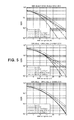
- FIGS. 5 to 7 show SER against SNR per symbol for various decoder implementations.
- a method of symbol detection in an electronic device employing multi-user multiple input multiple output (MU-MIMO) communication over a first transmission layer of first and second transmission layers comprising: receiving a transmitted signal; decoding the transmitted signal by detecting data symbols within the transmitted signal for the first transmission layer by performing Maximum Likelihood (ML) detection on the first transmission layer, wherein the step of performing ML detection comprises performing a search across all possible symbol constellation points in a set of constellation points available for the second transmission layer.
- the step of decoding may comprise demodulating the transmitted signal, whereby the transmitted signal has been modulated according to a digital modulation scheme.
- Such as scheme may be any orthogonal frequency digital modulation scheme, for example any one of: a zero point modulation scheme or a phase shift keying scheme, such as binary phase shift keying (BPSK), quadrature phase shift keying (QPSK), or a quadrature amplitude modulation scheme (QAM), such as QAM16 and QAM64 modulation schemes.
- Decoding can also comprise demodulating the received RF signal to baseband, prior to digital demodulation.
- the step of performing the search may comprise determining the most likely transmitted data symbols for the first transmission layer which result in the smallest symbol error for all data symbols across said all possible symbol constellation points.
- the method may further comprise outputting the most likely transmitted data symbols for the first transmission layer.
- the first transmission layer may comprise data symbols modulated based on constellation points which are a subset of the set of constellation points available for the second transmission layer.
- Said set of symbol constellation points for the second transmission layer may comprise a zero point and all points in QPSK, QAM16 and QAM64 modulation schemes, or all points in any one or both of PSK or QAM schemes.
- Said subset of symbol constellation points for the first transmission layer may consist of all points in one of any of the aforementioned modulation schemes, for example all points in any one or more of: QPSK, QAM16 and QAM64 modulation schemes.
- the zero point and all points in QPSK, QAM16 and QAM64 modulation schemes may collectively be referred to as QAM85, where 85 refers to the number of possible constellation points.
- Said set of symbol constellation points for the second transmission layer may comprise one or more of: the zero point, all points in QPSK, all points in QAM16, all points in QAM64, and all points in QAM128.
- said set of constellation points may be defined as all points in modulations schemes: QAMn (where n can be 2 i , where i is a positive integer, for example an integer i in the range 0 to 12, 0 to 10, 0 to 8, 0 to 7, 0 to 6, 0 to 5, 0 to 4, 0 to 3, 0 to 2, 0 and 1, or 0).
- n defines the number of constellation points in each modulation scheme.
- One or more of the modulation schemes may be utilised for the set, and all points in each utilised modulation scheme are used to form the set.
- the subset of symbol constellation points for the first transmission layer may consist of all points in one, or in one or more of the modulation schemes which form the set of symbol constellation points for the second transmission layer.
- the step of performing the search may further comprise performing the search across all possible symbol constellation points known for the first transmission layer and available for the second transmission layer.
- the first transmission layer may be the transmission layer assigned to the electronic device.
- the second transmission layer may be the transmission layer assigned to an additional device which is different to the electronic device.
- an electronic device comprising processing circuitry configured to perform any one of the above methods.
- a computer-readable medium comprising computer executable instructions which when executed by processing circuitry cause the processing circuitry to perform the steps of any one of the above methods.
- an electronic device for performing multi-user multiple input multiple output (MU-MIMO) communication over a first transmission layer of first and second transmission layers comprising: a receiver for receiving a transmitted signal; a decoder configured to decode the transmitted signal and detect data symbols within the transmitted signal for the first transmission layer by performing Maximum Likelihood (ML) detection on the first transmission layer with an ML detector, wherein the ML detector is configured to perform a search across all possible symbol constellation points in a set of constellation points available for the second transmission layer.
- ML Maximum Likelihood
- the decoder may comprise the ML detector.
- the decoder may be further configured to determine the most likely transmitted data symbols for the first transmission layer which result in the smallest symbol error for all data symbols across said all possible symbol constellation points.
- the decoder may be further configured to output the most likely transmitted data symbols for the first transmission layer.
- the first transmission layer may comprise data symbols modulated based on constellation points which are a subset of the set of constellation points available for the second transmission layer.
- Said set of symbol constellation points for the second transmission layer may comprise a zero point and all points in QPSK, QAM16 and QAM64 modulation schemes.
- Said subset of symbol constellation points for the first transmission layer may consist of all points in one of: QPSK, QAM16 and QAM64 modulation schemes.
- the step of performing the search may further comprise performing the search across all possible symbol constellation points known for the first transmission layer and available for the second transmission layer.
- the first transmission layer may be the transmission layer assigned to the electronic device.
- the second transmission layer may be the transmission layer assigned to an additional device which is different to the electronic device.
- a computer-readable medium comprising computer executable instructions which when executed by processing circuitry cause the processing circuitry to perform the steps of: receiving a transmitted signal; and decoding the transmitted signal by detecting data symbols within the transmitted signal for the first transmission layer by performing Maximum Likelihood (ML) detection on the first transmission layer, wherein the step of performing ML detection comprises performing a search across all possible symbol constellation points in a set of constellation points available for the second transmission layer.
- ML Maximum Likelihood
- the computer-readable medium may be non-transitory.
- the computer-readable medium may be a carrier comprising computer-executable instructions.
- the computer-readable medium may comprise a memory.
- the memory may be any of: random access memory (RAM), read-only memory (ROM), a CD-ROM and DVD.
- RAM random access memory
- ROM read-only memory
- CD-ROM compact disc-read only memory
- DVD digital versatile disc-read only memory
- the memory may be connected to processing circuitry which is configured to execute the instructions.
- FIG. 1 is an example of a communication system 100 which could employ the present invention.
- the communication system 100 comprises user equipment (UE) 150 which is an electronic device, such as a communication device, mobile device or phone, portable computing device, e.g. laptop or tablet device, or any other device which is adapted to communicate with the system 100 .
- the user equipment (UE) 150 comprises processing circuitry 156 in communication with memory 158 .
- the processing circuitry 156 is also in communication with signal processing circuitry 154 which is connected to antenna 152 .
- the user equipment 150 may also include many other commonplace features which are likely to well-understood by the skilled person. These commonplace features are not shown in FIG.
- Such commonplace features may be directly or indirectly connected to each other, to the processing circuitry 156 , memory 158 and/or signal processing circuitry 154 , and be in direct or indirect communication with each other, the processing circuitry 156 , memory 158 and/or signal processing circuitry 154 .
- the communication system 100 also comprises a remote station 160 , which may be a mobile station (MS), such as a mobile base station or any other device which is capable of communicating within the system 100 and with the user equipment 150 .
- the station 160 may comprise station antenna 162 and signal processing and control circuitry (not shown), which may be directly or indirectly connected to the station antenna 162 , and which may be similar or identical to the components of the user equipment (UE) as herein described.
- Radio frequency (RF) signals 122 are generated by the user equipment 150 and the station 160 and pass between each other via the antenna 152 and station antenna 162 , thereby permitting bi-directional communication between the user equipment 150 and the station 160 .
- the RF signals 122 are modulated or demodulated by the user equipment 150 and/or the station 160 according to one or more modulation/demodulation schemes, which permits data, for example digital data, to be transmitted between the station 160 and the user equipment 150 .
- the modulation schemes implemented by the communication system 100 including the user equipment 150 and station 160 may conform to one or more of various state-of the art schemes, such as those defined by as IEEE 802.11n (Wi-Fi), Third Generation Partnership Project (3GPP) Long Term Evolution (LTE) and Long Term Evolution Advanced (LTE-A), Worldwide Interoperability for Microwave Access (WiMAX) and High Speed Packet Access Evolution (HSPA+).
- the resulting communication network which is formed by the user equipment 150 (or a plurality thereof) and the station 160 (or a plurality thereof) may be a cellular communication network, such as a cellular network conforming to one or more of LTE, LTE-A or HSPA+.
- FIG. 2 is a generalised schematic of the signal processing circuitry 154 that might be employed comprising, at a transmitter 201 : a transmitter input 202 , a segmenter 204 , an encoder 206 , for example a turbo encoder, a formatter 208 , a modulator 210 ; a radio-frequency (RF) transmitter 212 .
- a receiver 221 there is: a receiver output 222 ; a decoder 224 , an equalizer 226 , a (baseband) demodulator 228 ; and a mixer 230 .
- the transmitter 201 and receiver 221 there may also be hardware which is shared, such as: the antenna 152 for receiving the RF signals 122 from the communications network, timing and control circuitry 252 , and an oscillator 254 , along with transmitter-receiver switch 256 .
- the transmitter 201 feeds a data stream to segmenter 204 where fixed-length data blocks of block size, K, are formed. These fixed-length data blocks are then passed to the encoder 206 which encodes the fixed length data blocks and sends the encoded data blocks successively as an encoded data stream to the formatter 208 .
- the formatter 208 generates, at a prescribed time and with a prescribed amplitude, signal bursts, each comprising a series of waveforms. These bursts are passed to modulator 210 where each burst is modulated to RF frequency by mixing it with a carrier having a known frequency.
- the transmitter 201 then transmits each modulated burst as the RF signal 122 when the transmitter-receiver switch 256 connects the antenna 152 to the transmitter 201 .
- the oscillator 254 which is connected to the modulator 210 tracks timing and is used by the modulator 210 to generate the carrier waveform.
- the timing and control circuitry 252 controls the formatting and timing of the bursts as generated by the formatter 208 .
- the receiver 221 when the antenna 152 receives the RF signal 122 containing a burst and the radio frequency (RF) receiver/mixer 230 is connected to the antenna 152 via the switch 256 , the received burst is amplified in the radio frequency (RF) receiver/mixer 230 , and then demodulated in the demodulator 228 so as to remove the RF carrier.
- the equalizer 226 filters each demodulated burst to produce an enhanced digital signal which is next decoded by decoder 224 .
- the decoder 224 decodes the digital signal and passes it via receiver output 222 to the processing circuitry 156 within the user equipment 150 for use and/or further processing.
- the decoder 224 may wholly or partially be implemented in hardware, or implemented in software executable on dedicated or shared processing circuitry, or implemented partially for certain elements in software, with other elements implemented hardware.
- the processing circuitry 156 may perform all or certain elements of the signal processing of the decoder 224 as described below.
- the signal processing circuitry 154 may comprise dedicated processing circuitry and memory for performing all or certain elements of the signal processing as described below.
- the decoder 224 provides and/or comprises, via hardware, or software or a combination of the two, a ML signal detector/decoder.
- FIG. 3 shows the constellation points for three different modulation orders which are, for example supported by LTE/LTE-A across multiple layers between multiple UEs. These orders are:
- the example ML decoder 224 is configured such that it makes an assumption about the search space of the modulation scheme or order of other UEs operating on the same communication channel having multiple layers, and then performs a search across the entire search space to minimise the Symbol Error Rate (SER), and thereby output a digital signal which provides minimal SER for all assumed modulation schemes.
- SER Symbol Error Rate
- This provides superior detection quality for single layer transmission in the context of MU-MIMO and simultaneous transmission on the other layer.
- the ML decoder 224 is utilised in a customized way on the basis that the modulation order of the other layer is not known.
- the modulation order of the wanted/desired layer is known, meaning that, for this layer, there is no need to extend the search space for the constellation points.
- the method and decoder 224 disclosed herein can be applied in MU-MIMO scenarios of any state-of-the-art communication system (as mentioned above).
- LTE Release 9
- TM8 in case of LTE-A (Release 10)
- TM9 in case of LTE-A (Release 10)
- TM9 in case of LTE-A (Release 10)
- the performance of the exemplary ML detector 224 in comparison to other forms of MIMO detection, such as ZF detection, MMSE detection and ML detection (when the modulation scheme is of the other UE is known) is illustrated with reference to FIGS. 5 to 7 which are further discussed below.
- the performance of the various detection schemes of these figures is determined based on an exemplary MIMO system 400 which is illustrated in FIG. 4 .
- a base station (eNb) 403 generates two payload data streams, i.e. Physical Downlink Shared Channels (PDSCHs), for two layers: layer 1 (L1) contains data for a first UE (UE1) 401 and layer 2 (L2) contains data for a second UE (UE2) 402. Additionally each layer contains also dedicated pilots, so called demodulation reference signals (DMRS), which are required for signal detection for UE1 and UE2, respectively.
- DMRS demodulation reference signals
- the PDSCH/DMRS data for each layer is modulated in modulator 404 using either Quadrature Phase Shift Keying (QPSK) or Quadrature Amplitude Modulation (QAM), e.g. QAM16 or QAM64 modulation.
- QPSK Quadrature Phase Shift Keying
- QAM Quadrature Amplitude Modulation
- the complex modulation symbols of layer 1 and layer 2 are precoded together using a 2 ⁇ 2 precoding matrix W in precoder 405 and transmitted as RF signals 122 at the same time via two antenna elements over the same physical resource.
- the transmitted data experiences the channel H and is received from UE1 via two receive antennas, where additive white Gaussian noise (AWGN) noise can be assumed.
- AWGN additive white Gaussian noise
- the noise can be estimated based on cell-specific reference signals (RS). Based on this information the detection and demodulation processing using ZF, MMSE or ML is applied, resulting in the estimated symbol sequence, which is then compared with the transmitted symbol sequence to calculate the symbol error rate (SER), which is a measure of the detection quality.
- SER symbol error rate
- the signal processing for UE2 is identical to the description related to UE1 401 and omitted here.
- the layer 2 data for UE2 402 acts as interference for data of layer 1 for UE1 401 and vice versa.
- the decoder 224 assumes that a set of constellation points (e.g. comprising points for multiple modulation schemes) is available for layer 2 and knows what constellation points (e.g. which single modulation scheme) has been utilised for layer 1.
- the decoder performs a search across all combinations of points which result from the combination of the known set for layer 1 and the assumed set for layer 2. In essence, for each constellation point on layer 1, the constellation point on layer 2 is found which minimizes the SER, e.g. the log-likelihood (LLR) metric
- LLR log-likelihood
- the decoder 224 performs minimisation of the SER for all other constellation points in the set of constellation points available for layer 2 (e.g. 1 point for the zero-point, 4 points for QPSK, 16 points for QAM16 and 64 points for QAM64).
- X is unknown, and is or corresponds to the determined transmitted signal
- H and U are constant for a particular channel configuration
- Y is or corresponds to the received signal.
- CSI channel state information
- FIGS. 5 to 7 represent simulated results based on the system 400 of FIG. 4 employing, for exemplary purposes, TM8 and TM9 of LTE/LTE-A according to section B.4.1 of 3GPP TS 36.101: User Equipment (UE) radio transmission and reception (Release 10), V10.9.0.
- UE User Equipment
- Detector 224 is an ML detector in which a set of one or more modulation schemes with corresponding constellation points is assumed for the other layer (e.g. layer 2), and where at a given time, a single modulation scheme is known for the desired layer (e.g. layer 1).
- Detector 224 a is either an ML detector with explicit knowledge of the single modulation scheme currently being utilised on the other layer, or is an MMSE, or ZF detector.
- FIG. 5 shows charts of SER against SNR per Symbol (db) for layer 1 (L1) utilising QPSK and layer 2 (L2) utilising QPSK, QAM16 or QAM64, based on an Extended Vehicular A model (EVA) channel.
- EVA Extended Vehicular A model
- FIG. 6 shows charts of SER against SNR per Symbol (db) for layer 1 (L1) utilising QAM64 and layer 2 (L2) utilising QPSK, QAM16 or QAM64, based on an Extended Vehicular A model (EVA) channel.
- EVA Extended Vehicular A model
- FIG. 7 shows charts of SER against SNR per Symbol (db) for layer 1 (L1) utilising QAM64 and layer 2 (L2) utilising QPSK, QAM16 or QAM64, based on an Extended Vehicular A model (EVA) channel.
- EVA Extended Vehicular A model
- the ML detector and QAM64 assumption achieves optimum ML performance if the modulation order of the other layer is QAM64.
- the SER performance is better than MMSE performance for SNR less than approx. 22 dB or SNR less than approx. 17 dB, respectively.
- the ML detector and search space extension to QAM85 for the other layer achieves best SER performance of all compared detectors compared to the reference.
- the difference to the reference ML solution is caused by the lack of a priori information of the modulation order of the other layer.
Abstract
Description
-
- QPSK (4 constellation points 301);
- QAM16 (16 constellation points 302); and
- QAM64 (64 constellation points 303).
-
- H is the channel matrix of size Nrx×Ntx (Ntx=number of transmitting (Tx) antennas, Nrx=number of receiving (Rx) antennas);
- W is the precoding matrix used (Ntx×NL) (NL=number of transmitted layers); and
- Heff is the effective channel matrix (Nrx×NL).
-
- H is the channel matrix of size Nrx×Ntx (Ntx=number of transmitting (Tx) antennas, Ntx=number of receiving (Rx) antennas);
- Y is the received signal vector (Nrx×1);
- X is the transmitted signal vector (NL×1); and
- U is the inverse square root of the noise covariance matrix (Nrx×Nrx).
-
- Two layer transmission,
layer 1 is for the UE1 (wanted) and layer 2 is for UE2 (unwanted, acts as interfering signal) - Both layers are precoded using random 2×2 precoding matrices W according to section B.4.1 of [1]
- Ideal channel estimation is assumed, meaning the effective channel matrices Heff=H*W are perfectly known for each subcarrier at the UE.
- Three detector types are considered: ZF, MMSE and ML based solutions
- No colored noise assumed, meaning the noise covariance matrix is just a diagonal matrix and no noise pre-whitening is required. However, the effects of colored spatial noise could be included for ML detection.
- Low antenna correlation for Tx and Rx is assumed.
- Only the SER (Symbol Error Rate) is evaluated, as this is sufficient to compare the detection performances of the three different detectors.
- Two layer transmission,
-
- ML detector with knowledge of the modulation order of the other layer (reference);
- Method 1: ML detector assuming QAM64 on the other layer;
- Method 2: ML detector & Search Space Extension to QAM85 for the other layer;
- MMSE detector; and
- ZF detector.
-
- The smaller the modulation order, the bigger the performance gap is between ZF and MMSE.
- The ZF and MMSE performance is independent of the modulation order of the 2nd layer, as this parameter is not taken into account at all in the detection process.
- Method 1: In the case of ML and QAM64 assumption for the 2nd layer, a residual error is caused if the modulation assumption of the 2nd layer is wrong. This residual error depends on the minimum distance between the constellation points of the QAM64 grid and the constellation points of the QPSK and QAM16 grid. QAM16 on the 2nd layer is the worst case.
- Method 2: ML and QAM85 (combination of QAM64, QAM16, QPSK and zero-point) outperforms the ZF, MMSE and the ML with QAM64 assumption. Note that for ML and QAM85 the SER performance is independent of the modulation order of the 2nd layer, since all possible constellation points are always taken into account. The lack of knowledge about the used modulation order of the other (interfering) layer can be interpreted as a lack in a priori information, which leads to significant SER performance drop compared to the reference.
- The higher the modulation order of the 2nd layer, the worse the interference is for the 1st layer and vice versa for the reference (ML & known modulation) in the case of fixed channel conditions.
-
- For QAM16, the performance gap between ZF and MMSE is much smaller compared to QPSK.
- The ZF and MMSE performance is independent of the modulation order of the 2nd layer, as this parameter is not taken into account at all in the detection process.
- Method 1: In case of ML and QAM64 assumption for the 2nd layer, a residual error is caused if the modulation assumption of the 2nd layer is wrong. This residual error depends on the minimum distance between the constellation points of the QAM64 grid and the constellation points of the QPSK and QAM16 grid. QAM16 on the 2nd layer is the worst case.
- Method 2: “ML and QAM85” (combination of QAM64, QAM16, QPSK and zero-point) outperforms the ZF, MMSE and the “ML with QAM64 assumption”. Note that for ML and QAM85 the SER performance is independent of the modulation order of the 2nd layer, as always all possible constellation points are taken into account. The lack of knowledge about the used modulation order of the other (interfering) layer can be interpreted as a lack in a priori information, which leads to significant SER performance drop compared to the reference.
- The higher the modulation order of the 2nd layer, the worse the interference is for the 1st layer and vice versa for the reference (ML & known modulation) in the case of fixed channel conditions.
-
- For QAM64, the performance gap between ZF and MMSE is much smaller compared to QAM16.
- The ZF and MMSE performance is independent of the modulation order of the 2nd layer, as this parameter is not taken into account at all in the detection process.
- Method 1: In the case of ML and QAM64 assumption for the 2nd layer, a residual error is caused if the modulation assumption of the 2nd layer is wrong. This residual error depends on the minimum distance between the constellation points of the QAM64 grid and the constellation points of the QPSK and QAM16 grid. QAM16 on the 2nd layer is the worst case.
- Method 2: “ML and QAM85” (combination of QAM64, QAM16, QPSK and zero-point) outperforms the ZF, MMSE and the “ML with QAM64 assumption”. Note that for ML and QAM85 the SER performance is independent of the modulation order of the 2nd layer, as always all possible constellation points are taken into account. The lack of knowledge about the used modulation order of the other (interfering) layer can be interpreted as a lack in a priori information, which leads to significant SER performance drop compared to the reference.
- The higher the modulation order of the 2nd layer, the worse the interference is for the 1st layer and vice versa for the reference (ML & known modulation) in case of fixed channel conditions.
Claims (27)
Priority Applications (1)
| Application Number | Priority Date | Filing Date | Title |
|---|---|---|---|
| US14/013,715 US9112660B2 (en) | 2013-08-29 | 2013-08-29 | Maximum likelihood detection |
Applications Claiming Priority (1)
| Application Number | Priority Date | Filing Date | Title |
|---|---|---|---|
| US14/013,715 US9112660B2 (en) | 2013-08-29 | 2013-08-29 | Maximum likelihood detection |
Publications (2)
| Publication Number | Publication Date |
|---|---|
| US20150063503A1 US20150063503A1 (en) | 2015-03-05 |
| US9112660B2 true US9112660B2 (en) | 2015-08-18 |
Family
ID=52583269
Family Applications (1)
| Application Number | Title | Priority Date | Filing Date |
|---|---|---|---|
| US14/013,715 Active US9112660B2 (en) | 2013-08-29 | 2013-08-29 | Maximum likelihood detection |
Country Status (1)
| Country | Link |
|---|---|
| US (1) | US9112660B2 (en) |
Families Citing this family (3)
| Publication number | Priority date | Publication date | Assignee | Title |
|---|---|---|---|---|
| US9590757B2 (en) * | 2014-09-23 | 2017-03-07 | Nxp Usa, Inc. | Equalizer for joint-equalization |
| US10791548B2 (en) * | 2016-05-02 | 2020-09-29 | Qualcomm Incorporated | Search space design for control channel in wireless communication |
| CN110753012A (en) * | 2019-11-25 | 2020-02-04 | 重庆邮电大学 | Multi-user detection algorithm of time reversal multiple access system |
Citations (1)
| Publication number | Priority date | Publication date | Assignee | Title |
|---|---|---|---|---|
| US20130287150A1 (en) * | 2012-04-26 | 2013-10-31 | Motorola Mobility, Inc. | Method and apparatus for demodulating a signal in a communication system |
-
2013
- 2013-08-29 US US14/013,715 patent/US9112660B2/en active Active
Patent Citations (1)
| Publication number | Priority date | Publication date | Assignee | Title |
|---|---|---|---|---|
| US20130287150A1 (en) * | 2012-04-26 | 2013-10-31 | Motorola Mobility, Inc. | Method and apparatus for demodulating a signal in a communication system |
Also Published As
| Publication number | Publication date |
|---|---|
| US20150063503A1 (en) | 2015-03-05 |
Similar Documents
| Publication | Publication Date | Title |
|---|---|---|
| Duplicy et al. | Mu-mimo in lte systems | |
| Saito et al. | Performance and design of SIC receiver for downlink NOMA with open-loop SU-MIMO | |
| US9088443B2 (en) | Channel estimation and interference cancellation for virtual MIMO demodulation | |
| US8699528B2 (en) | Systems and methods for communication using dedicated reference signal (DRS) | |
| US8774151B2 (en) | Closed-loop MIMO systems and methods | |
| US8995592B2 (en) | Signaling to support advanced wireless receivers and related devices and methods | |
| US10374859B2 (en) | Apparatus and method for pre-processing for filter bank multi carrier scheme in wireless communication system | |
| US20150249553A1 (en) | Channel estimation in a multi-antenna wireless communications system | |
| WO2022000268A1 (en) | Indication of doppler pre-compensation in multi-transmission reception point communications | |
| US9112660B2 (en) | Maximum likelihood detection | |
| EP3224965A1 (en) | Method and device for efficient precoder search | |
| WO2021253664A1 (en) | Doppler shift reporting for multiple transmission reception points | |
| US20190149362A1 (en) | Hybrid mimo detection of ofdm signals | |
| Lee et al. | Interference cancellation based on blindly-detected interference parameters for LTE-advanced UE | |
| US8989322B2 (en) | Data detection and receiver circuit | |
| US20210067261A1 (en) | Method and apparatus for network assisted interference cancellation and suppression in wireless cellular communication system | |
| Bai et al. | Receiver performance-complexity tradeoff in LTE MU-MIMO transmission | |
| US8964908B2 (en) | Receiver circuit and method for detecting data | |
| US11936410B2 (en) | Power amplifier model estimation for digital post distortion in multi-antenna devices | |
| US20230379080A1 (en) | Techniques for implementing reed-solomon coding | |
| US11689258B2 (en) | Channel estimation and demodulation procedure for non-linear multi-user multiple-input multiple-output precoding | |
| US20230246691A1 (en) | Inter-stream interference measurement for non-linear precoding techniques | |
| US20240146579A1 (en) | Joint gain and phase mismatch canceller and equalizer for downlink aided by precoder signaling | |
| Kaltenberger et al. | Experimental analysis of network-aided interference-aware receiver for LTE MU-MIMO | |
| US20230224884A1 (en) | Enhanced per-stream recursive demapping techniques |
Legal Events
| Date | Code | Title | Description |
|---|---|---|---|
| AS | Assignment |
Owner name: BLACKBERRY LIMITED, ONTARIO Free format text: CHANGE OF NAME;ASSIGNOR:RESEARCH IN MOTION LIMITED;REEL/FRAME:034077/0227 Effective date: 20130709 |
|
| AS | Assignment |
Owner name: BLACKBERRY DEUTSCHLAND GMBH, GERMANY Free format text: ASSIGNMENT OF ASSIGNORS INTEREST;ASSIGNOR:KOSAKOWSKI, MARTIN;REEL/FRAME:036076/0001 Effective date: 20150413 |
|
| STCF | Information on status: patent grant |
Free format text: PATENTED CASE |
|
| AS | Assignment |
Owner name: BLACKBERRY LIMITED, ONTARIO Free format text: ASSIGNMENT OF ASSIGNORS INTEREST;ASSIGNOR:BLACKBERRY DEUTSCHLAND GMBH;REEL/FRAME:036219/0702 Effective date: 20150715 |
|
| MAFP | Maintenance fee payment |
Free format text: PAYMENT OF MAINTENANCE FEE, 4TH YEAR, LARGE ENTITY (ORIGINAL EVENT CODE: M1551); ENTITY STATUS OF PATENT OWNER: LARGE ENTITY Year of fee payment: 4 |
|
| AS | Assignment |
Owner name: BLACKBERRY DEUTSCHLAND GMBH, GERMANY Free format text: CHANGE OF NAME;ASSIGNOR:RESEARCH IN MOTION DEUTSCHLAND GMBH;REEL/FRAME:058751/0262 Effective date: 20130724 Owner name: BLACKBERRY LIMITED, ONTARIO Free format text: ASSIGNMENT OF ASSIGNORS INTEREST;ASSIGNOR:BLACKBERRY UK LIMITED;REEL/FRAME:058125/0070 Effective date: 20211116 Owner name: BLACKBERRY UK LIMITED, UNITED KINGDOM Free format text: ASSIGNMENT OF ASSIGNORS INTEREST;ASSIGNOR:LEACH, MARTIN GEOFFREY;REEL/FRAME:058125/0038 Effective date: 20100115 Owner name: RESEARCH IN MOTION DEUTSCHLAND GMBH, GERMANY Free format text: ASSIGNMENT OF ASSIGNORS INTEREST;ASSIGNOR:HEMMING, ERWIN;REEL/FRAME:058124/0892 Effective date: 20080430 |
|
| MAFP | Maintenance fee payment |
Free format text: PAYMENT OF MAINTENANCE FEE, 8TH YEAR, LARGE ENTITY (ORIGINAL EVENT CODE: M1552); ENTITY STATUS OF PATENT OWNER: LARGE ENTITY Year of fee payment: 8 |
|
| AS | Assignment |
Owner name: MALIKIE INNOVATIONS LIMITED, IRELAND Free format text: ASSIGNMENT OF ASSIGNORS INTEREST;ASSIGNOR:BLACKBERRY LIMITED;REEL/FRAME:064104/0103 Effective date: 20230511 |
|
| AS | Assignment |
Owner name: MALIKIE INNOVATIONS LIMITED, IRELAND Free format text: NUNC PRO TUNC ASSIGNMENT;ASSIGNOR:BLACKBERRY LIMITED;REEL/FRAME:064271/0199 Effective date: 20230511 |