US9110322B2 - LCD module and assembling method thereof - Google Patents
LCD module and assembling method thereof Download PDFInfo
- Publication number
- US9110322B2 US9110322B2 US13/807,743 US201213807743A US9110322B2 US 9110322 B2 US9110322 B2 US 9110322B2 US 201213807743 A US201213807743 A US 201213807743A US 9110322 B2 US9110322 B2 US 9110322B2
- Authority
- US
- United States
- Prior art keywords
- assembling
- lcd
- backplane
- module
- backlight module
- Prior art date
- Legal status (The legal status is an assumption and is not a legal conclusion. Google has not performed a legal analysis and makes no representation as to the accuracy of the status listed.)
- Expired - Fee Related, expires
Links
- 238000000034 method Methods 0.000 title claims description 20
- 239000004973 liquid crystal related substance Substances 0.000 claims abstract description 19
- 239000012788 optical film Substances 0.000 claims description 21
- 239000000725 suspension Substances 0.000 claims description 3
- 238000009434 installation Methods 0.000 description 21
- NJPPVKZQTLUDBO-UHFFFAOYSA-N novaluron Chemical compound C1=C(Cl)C(OC(F)(F)C(OC(F)(F)F)F)=CC=C1NC(=O)NC(=O)C1=C(F)C=CC=C1F NJPPVKZQTLUDBO-UHFFFAOYSA-N 0.000 description 13
- 230000000712 assembly Effects 0.000 description 12
- 238000000429 assembly Methods 0.000 description 12
- 238000010586 diagram Methods 0.000 description 6
- 238000004519 manufacturing process Methods 0.000 description 3
- 238000003466 welding Methods 0.000 description 1
Images


Classifications
-
- G—PHYSICS
- G02—OPTICS
- G02F—OPTICAL DEVICES OR ARRANGEMENTS FOR THE CONTROL OF LIGHT BY MODIFICATION OF THE OPTICAL PROPERTIES OF THE MEDIA OF THE ELEMENTS INVOLVED THEREIN; NON-LINEAR OPTICS; FREQUENCY-CHANGING OF LIGHT; OPTICAL LOGIC ELEMENTS; OPTICAL ANALOGUE/DIGITAL CONVERTERS
- G02F1/00—Devices or arrangements for the control of the intensity, colour, phase, polarisation or direction of light arriving from an independent light source, e.g. switching, gating or modulating; Non-linear optics
- G02F1/01—Devices or arrangements for the control of the intensity, colour, phase, polarisation or direction of light arriving from an independent light source, e.g. switching, gating or modulating; Non-linear optics for the control of the intensity, phase, polarisation or colour
- G02F1/13—Devices or arrangements for the control of the intensity, colour, phase, polarisation or direction of light arriving from an independent light source, e.g. switching, gating or modulating; Non-linear optics for the control of the intensity, phase, polarisation or colour based on liquid crystals, e.g. single liquid crystal display cells
- G02F1/133—Constructional arrangements; Operation of liquid crystal cells; Circuit arrangements
- G02F1/1333—Constructional arrangements; Manufacturing methods
- G02F1/133308—Support structures for LCD panels, e.g. frames or bezels
- G02F1/133314—Back frames
-
- G02F2001/133314—
-
- Y—GENERAL TAGGING OF NEW TECHNOLOGICAL DEVELOPMENTS; GENERAL TAGGING OF CROSS-SECTIONAL TECHNOLOGIES SPANNING OVER SEVERAL SECTIONS OF THE IPC; TECHNICAL SUBJECTS COVERED BY FORMER USPC CROSS-REFERENCE ART COLLECTIONS [XRACs] AND DIGESTS
- Y10—TECHNICAL SUBJECTS COVERED BY FORMER USPC
- Y10T—TECHNICAL SUBJECTS COVERED BY FORMER US CLASSIFICATION
- Y10T29/00—Metal working
- Y10T29/49—Method of mechanical manufacture
- Y10T29/49002—Electrical device making
- Y10T29/49117—Conductor or circuit manufacturing
Definitions
- the present disclosure relates to the field of liquid crystal displays (LCDs), and more particularly to an LCD module and assembling method thereof.
- LCDs liquid crystal displays
- a liquid crystal display is widely used in life and work because the LCD has various characteristics such as being light weight, thin, and have a large display area.
- the LCD generally includes a backlight module, an LCD panel assembly, a front frame, and a printed circuit board.
- the backlight module 101 includes a light source assembly 110 , a reflector plate 120 , a light guide plate (or a diffuser plate) 130 , a plurality of optical films 140 and a middle frame that fixes the optical films 140 , and a power panel 160 that controls the light source assembly 110 .
- the LCD panel assembly 170 includes an LCD panel 171 , a flexible printed circuit board 172 , and a signal timer-control printed circuit board 173 .
- the LCD panel assembly 170 is fixed to the backlight module 101 via a front frame 180 to form an LCD module 100 .
- FIG. 2 shows a production and assembly procedures for the LCDs under sixty inches.
- Steps for assembling the LCDs under sixty inches comprises: a) horizontally placing the backplane and mounting the light source assembly on the backplane, b) flipping the LCD to a back surface, turning on the light source assembly, and checking whether it is qualified, c) flipping the LCD to a front surface and installing the reflector plate, the light guide panel, the optical films and the middle frame, d) installing the LCD panel assembly and the front frame, e) flipping the LCD to the back surface and installing various printed circuit boards, and, f) flipping the LCD to the front surface and checking the display. In the process, four flips of the LCD are needed.
- An aim of the present disclosure is to provide a method for installing a liquid crystal display (LCD) module with higher safety and efficiency.
- LCD liquid crystal display
- An LCD module comprises a backplane configured with a fixed beam to vertically fix the backplane.
- two fixed beams arranged in parallel, are fixed onto the backplane, or three fixed beams are arranged on the backplane, the three fixed beams forming an H-shaped structure.
- a method for installing the LCD module comprising:
- A1) installing a backlight module step comprising: vertically fixing the backplane and installing components of the backlight module on the backplane to finish installation of the backlight module;
- A2) installing an LCD panel assembly step comprising: horizontally placing the installed backlight module and assembling the LCD panel assembly on the backlight module;
- installing the backlight module step comprises assembling a light source assembly, the light source assembly is locked to the vertical backplane.
- Each of the light source assembly is configured with a connecting wire and is connected to a power panel by the connecting wire, and thus this vertical state facilitates quick installation of the connecting wire.
- installing the backlight module step comprises installing a diffuser plate.
- a bottom of the backplane is configured with a first positioning structure that positions edges of the diffuser plate, and when the diffuser plate is installed, one edge of the diffuser plate is first positioned on the first positioning structure.
- a arrangement mode can ensure that the diffuser plate is reliable fixed, which prevent the diffuser plate from falling of before a middle frame is installed.
- the diffuser plate is fixed to the backplane via double sided tape.
- double sided tape can improve reliability of installation of the diffuser plate.
- installing the backlight module step comprises installing optical films.
- a second positioning structure is arranged on a top of the vertical backplane, the optical films are fixed to the second positioning structure in a suspension mode. In this way, the optical films can be temporarily fixed without horizontally placing the whole module to arrange the optical films, before a middle frame is installed.
- installing the backlight module step comprises installing a middle frame.
- the middle frame is divided into a plurality of segments, and each of the segments is fixed to a side-wall of the backplane with a screw. Because of larger size of the middle frame, dividing into a plurality of the segments can make it install easily.
- the step A2 further comprises looking a front frame to a side-wall of the horizontal backplane which conveniently installs the front frame on the horizontal module, when workers are installing, operating distance is more ergonomical.
- the method for installing the LCD module further comprises step A4: turning on the LCD module to check if a display image of the LCD module is normal, which confirms that the LCD module is installed properly or damaged.
- the backplane of the LCD module is configured with the fixed beams that supports the backplane to maintain the backplane in a vertical state
- the backlight module and an LCD assembly are installed during installation of the backplane when the backplane is in a vertical state.
- the LCD module only two flips are required when the LCD assembly is installed, one flip in the step for horizontally installing the LCD assembly, another flip in the step for vertically reinstalling the printed circuit board. Frequencies of the flips reduces, which reduces probability that the LCD module is damaged during the installation of the LCD module.
- a vertical mounting mode is adopted, the workers can stand to operate, accessible distance in operation can be larger, so that the operation distance can accommodate ergonomic comfortable distance to increase efficiency of production.
- FIG. 1 is a simplified structural diagram of a typical liquid crystal display (LCD) module
- FIG. 2 is a flow diagram of installation of a typical liquid crystal display (LCD) module
- FIG. 3 is a flow diagram of installation of a liquid crystal display (LCD) module of the present disclosure
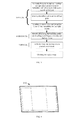
- FIG. 4 is a structural diagram of a backplane of a first example of the present disclosure
- FIG. 5 is a structural diagram of a backplane of a first example of the present disclosure
- FIG. 6 shows the first step of installation of a backlight module of a first example of the present disclosure
- FIG. 7 shows the steps of installation of a light source assembly of a first example of the present disclosure
- FIG. 8 shows the steps of installation of a reflector plate of a first example of the present disclosure
- FIG. 9 shows the steps of installation of a diffuser plate of a first example of the present disclosure
- FIG. 10 shows the steps of installation of the optical films of a first example of the present disclosure
- FIG. 11 shows the steps of installation of a first example of the present disclosure
- FIG. 12 shows an installed backlight module of a first example of the present disclosure
- FIG. 13 shows the steps of installation of a liquid crystal display (LCD) panel assembly of a first example of the present disclosure
- FIG. 14 shows the steps of installation of a front frame of a first example of the present disclosure
- FIG. 15 shows an installed liquid crystal display (LCD) module of a first example of the present disclosure
- FIG. 16 shows the steps of installation of the printed circuit boards and the wires of a liquid crystal display (LCD) module of a first example of the present disclosure
- FIG. 17 is a structural diagram of another backplane of a first example or a second example of the present disclosure.
- FIG. 4 to FIG. 17 Marks of FIG. 4 to FIG. 17 : 300 . backlight module; 310 . backplane; 311 . fixed beam; 200 . foot pedestal; 320 . light source assembly; 330 . reflector plate; 340 . diffuser plate; 350 , optical film; 360 . middle frame; 400 . LCD module; 410 . LCD panel assembly; 411 . printed circuit board; 420 . front frame; 430 . first printed circuit board; 440 , second printed circuit board; 450 . wire.
- This embodiment illustrates the present disclosure using a direct-light liquid crystal display (LCD) module (over sixty inches) as an example.
- LCD liquid crystal display
- the backplane 310 is formed by one or more pieces backplane formed by riveting, welding, locking through screws, etc.
- the backplane 310 of this embodiment comprises a structure spliced by a plurality of rectangular splicing blocks.
- FIG. 4 only shows a spliced backplane structure of the backplane, but the present disclosure should is not only limited to the spliced backplane structure.
- two fixed beams 311 arranged in parallel are fixed onto as back surface of the backplane 310 , the fixed beams 311 can improve strength of the spliced backplane and steadily support an LCD device during installing.
- the fixed beams 311 define hanging holes (not shown in this figure), so that the hanging holes can be used as a hanging device of the LCD device, without configuring to other hanging devices.
- one fixed beam is arranged between the two fixed beams 311 arranged in parallel to form an H-shaped fixed beam structure, which improves support strength of the fixed beams and also enhances structural strength of the backplane.
- the LCD module is installed, comprising:
- Step A1 Vertically Fixing the Backplane and Assembling the Backlight Module.
- the backplane can be installed and processed on a platform, as shown in FIG. 6 , the processed backplane 310 is fastened to a movable foot pedestal 200 , the fixed beam on the back surface of the backplane 310 defines hanging holes (not shown in this figure), the backplane 310 and the foot pedestal 200 can be locked by the hanging holes to fix the backplane 310 to the foot pedestal 200 , so that the backplane 310 can be supported and maintained in a vertical state.
- the foot pedestal 200 is configured with an all-around wheel, which facilitates transport of the backlight module in the assembly process and in choosing a installation position.
- each of the light source assemblies 320 is configured with a connecting wire and is connected to a power panel by the connecting wire, and thus this vertical state facilitates quick installation of the connecting wire.
- the light source assemblies 320 are turned on to check whether the light source assemblies are normal.
- a reflector plate 330 is installed.
- the reflector plate 330 is divided into a plurality of segments.
- the reflector plate of this embodiment is formed by a plurality of rectangular segments, which can reduce cost of the reflector plate.
- the reflector plate 330 defines a opening hole on the corresponding positions of the LED (not shown in this figure) where the LEDs are corresponded to the light source assemblies.
- the reflector plate 330 is fastened to surfaces of the light source assemblies by double sided tape.
- the diffuser plate 340 is installed.
- a first positioning structure (not shown in this figure) is arranged at a bottom of the vertical backplane 310 , one edge of the diffuser plate 340 is arranged against the first positioning structure, the first positioning structure is a neck or a lug at the bottom of the vertical backplane to position the edges of the diffuser plate and the diffuser plate 340 is bonded to the diffuser plate 340 via the double sided tape, which prevents the diffuser plate 340 from falling off from the backplane 310 .
- the optical films 350 are installed.
- a plurality of optical films 350 are arranged in the backlight module.
- the optical films 350 are hanged on a second positioning structure (not shown in this figure) on the top of the backplane 310 in a suspension mode, such as, hooks or buckle clamps are used to fix at the top of the optical films 350 .
- a suspension mode such as, hooks or buckle clamps are used to fix at the top of the optical films 350 .
- the optical films can be temporarily fixed without horizontally placing the whole module to arrange the optical films, before a middle frame is installed.
- the middle frame 360 is installed.
- the middle frame 360 is generally made of plastic, and because the LCD module is over-sized, the plastic middle frame 360 is divided into a plurality of sections to form a multi-section middle frame which is convenient to install.
- On the vertical backplane 310 a plurality of sections of the middle frame 360 are successively installed on the backplane 310 via screws.
- FIG. 12 after the middle frame 360 is installed, the components of the backlight module 300 are installed.
- Step A2 Installing an LCD Panel Assembly, Horizontally Placing the Installed Backlight Module, and Installing the LCD Panel Assembly on the Backlight Module.
- the installed backlight module is arranged on a flat platform (not shown in this figure), which is a first of the LCD module in installing, the first flip of the LCD module can be achieved by a machine flip platform used as a supporting platform in a horizontal position. Then, the LCD panel assembly 410 is installed, the printed circuit board 411 of the LCD panel assembly 410 is fixed, and installation of the LCD panel assembly is finished.
- a front frame 420 is installed.
- the front frame 420 is locked to the backplane of the backlight module 300 in horizontally state, thus, the LCD module 400 as shown in FIG. 15 is formed.
- Step A3 Installing the Printed Circuit Boards of the LCD Module, Vertically Fixing the Backlight Module and the LCD Panel Assembly of the Backlight Module Again, and Installing the Printed Circuit Board.
- a first printed circuit board 430 As shown in FIG. 16 , after the front frame 420 is installed, a first printed circuit board 430 , a second printed circuit board 440 and the corresponding wires 450 are installed.
- the LCD module 400 is erected again and fixed with the movable foot pedestal 200 , which is a second flip. Then, the first printed circuit hoard 430 , the second printed circuit hoard 440 and the corresponding wires 450 are installed.
- the printed circuit boards are installed in the vertical state and the operating distance is more ergonomical, which improve efficiency.
- the LCD module is turned on to check if a display image of the LCD module is normal, if the display image of the LCD module is normal, the installation of the LCD module is completed.
- the LCD module of this embodiment adopts a edge-light mode.
- a difference between the two examples is that, in the second example, the light source assemblies are fastened to side-walls of the backplane and a light guide plate converts edge-light into a surface light source, but in the first example, the light source assemblies are arranged on the surface of the backplane.
- the installing process of the present disclosure can comprise:
- the LCD module In the steps a1 to a3, the LCD module is in as vertical state; in the step a4, the LCD module is horizontally arranged on a platform, and in the steps a5 to a6, the LCD module is in the vertical state. Only two flips are required in this whole process, which reduces probability that the LCD module is damaged during flipping and moving.
Landscapes
- Physics & Mathematics (AREA)
- Nonlinear Science (AREA)
- Mathematical Physics (AREA)
- Chemical & Material Sciences (AREA)
- Crystallography & Structural Chemistry (AREA)
- General Physics & Mathematics (AREA)
- Optics & Photonics (AREA)
- Devices For Indicating Variable Information By Combining Individual Elements (AREA)
- Liquid Crystal (AREA)
Abstract
Description
Claims (8)
Applications Claiming Priority (4)
| Application Number | Priority Date | Filing Date | Title |
|---|---|---|---|
| CN201210544127.0A CN103048812B (en) | 2012-12-14 | 2012-12-14 | Liquid crystal display module and packaging method |
| CN201210544127 | 2012-12-14 | ||
| CN201210544127.0 | 2012-12-14 | ||
| PCT/CN2012/087247 WO2014089878A1 (en) | 2012-12-14 | 2012-12-24 | Liquid crystal display module and assembling method therefor |
Publications (2)
| Publication Number | Publication Date |
|---|---|
| US20140168563A1 US20140168563A1 (en) | 2014-06-19 |
| US9110322B2 true US9110322B2 (en) | 2015-08-18 |
Family
ID=50930479
Family Applications (1)
| Application Number | Title | Priority Date | Filing Date |
|---|---|---|---|
| US13/807,743 Expired - Fee Related US9110322B2 (en) | 2012-12-14 | 2012-12-24 | LCD module and assembling method thereof |
Country Status (1)
| Country | Link |
|---|---|
| US (1) | US9110322B2 (en) |
Families Citing this family (3)
| Publication number | Priority date | Publication date | Assignee | Title |
|---|---|---|---|---|
| KR102040612B1 (en) * | 2013-08-21 | 2019-11-05 | 엘지전자 주식회사 | Display device |
| CN109416896B (en) | 2016-07-15 | 2022-03-01 | 索尼公司 | Display device |
| CN110223542A (en) * | 2019-05-15 | 2019-09-10 | 广州视源电子科技股份有限公司 | Display module and wisdom blackboard |
Citations (3)
| Publication number | Priority date | Publication date | Assignee | Title |
|---|---|---|---|---|
| US20090173860A1 (en) * | 2008-01-04 | 2009-07-09 | Bell'o International Corp. | Mounting system for flat panel display |
| US20090184221A1 (en) * | 2008-01-04 | 2009-07-23 | Bell'o International Corp. | Flat panel display mounting |
| US20140021312A1 (en) * | 2012-07-17 | 2014-01-23 | My Nguyen | Flat Panel Wall Mount |
-
2012
- 2012-12-24 US US13/807,743 patent/US9110322B2/en not_active Expired - Fee Related
Patent Citations (3)
| Publication number | Priority date | Publication date | Assignee | Title |
|---|---|---|---|---|
| US20090173860A1 (en) * | 2008-01-04 | 2009-07-09 | Bell'o International Corp. | Mounting system for flat panel display |
| US20090184221A1 (en) * | 2008-01-04 | 2009-07-23 | Bell'o International Corp. | Flat panel display mounting |
| US20140021312A1 (en) * | 2012-07-17 | 2014-01-23 | My Nguyen | Flat Panel Wall Mount |
Also Published As
| Publication number | Publication date |
|---|---|
| US20140168563A1 (en) | 2014-06-19 |
Similar Documents
| Publication | Publication Date | Title |
|---|---|---|
| CN103543543B (en) | Frame-free liquid crystal display device | |
| CN101435948B (en) | Backlight module and liquid crystal display including same | |
| US8659716B2 (en) | Flat panel display and method for assembling the flat panel display | |
| US10001670B2 (en) | Supporting member for backlight unit, backlight unit and image display apparatus having the same | |
| US7891859B2 (en) | Frame and backlight module using the same | |
| EP2474780A1 (en) | Backlight module and rubber frame unit structure thereof | |
| CN203082680U (en) | Backlight module and display device using same | |
| US9188800B2 (en) | Liquid crystal display device | |
| US20180101043A1 (en) | Liquid crystal display device | |
| WO2014089878A1 (en) | Liquid crystal display module and assembling method therefor | |
| US9983426B2 (en) | Display module and display device comprising display module | |
| US20120287367A1 (en) | Liquid crystal display module and front frame structure thereof | |
| EP3564737B1 (en) | Liquid crystal display module and method of assembling thereof | |
| WO2023124290A1 (en) | Backlight module and display apparatus | |
| US9110322B2 (en) | LCD module and assembling method thereof | |
| WO2015096273A1 (en) | Spliced liquid crystal panel, assembly method therefor, and spliced television | |
| US8873228B2 (en) | LCD module and frame thereof | |
| US8817204B2 (en) | Liquid crystal display and liquid crystal display device including the same | |
| CN218788249U (en) | Display components and monitors | |
| CN204853358U (en) | Limit structure , backlight unit and display device | |
| CN202484772U (en) | Backlight module and display device | |
| CN102314805B (en) | Flat panel display and method of assembling flat panel display | |
| CN104566045B (en) | A direct type backlight module and its assembly method | |
| CN103913877B (en) | A kind of backlight module and display device | |
| CN212749462U (en) | Display module |
Legal Events
| Date | Code | Title | Description |
|---|---|---|---|
| AS | Assignment |
Owner name: SHENZHEN CHINA STAR OPTOELECTRONICS TECHNOLOGY CO. Free format text: ASSIGNMENT OF ASSIGNORS INTEREST;ASSIGNOR:TANG, GUOFU;REEL/FRAME:029545/0582 Effective date: 20121225 |
|
| FEPP | Fee payment procedure |
Free format text: PAYOR NUMBER ASSIGNED (ORIGINAL EVENT CODE: ASPN); ENTITY STATUS OF PATENT OWNER: LARGE ENTITY |
|
| ZAAA | Notice of allowance and fees due |
Free format text: ORIGINAL CODE: NOA |
|
| ZAAB | Notice of allowance mailed |
Free format text: ORIGINAL CODE: MN/=. |
|
| STCF | Information on status: patent grant |
Free format text: PATENTED CASE |
|
| MAFP | Maintenance fee payment |
Free format text: PAYMENT OF MAINTENANCE FEE, 4TH YEAR, LARGE ENTITY (ORIGINAL EVENT CODE: M1551); ENTITY STATUS OF PATENT OWNER: LARGE ENTITY Year of fee payment: 4 |
|
| FEPP | Fee payment procedure |
Free format text: MAINTENANCE FEE REMINDER MAILED (ORIGINAL EVENT CODE: REM.); ENTITY STATUS OF PATENT OWNER: LARGE ENTITY |
|
| LAPS | Lapse for failure to pay maintenance fees |
Free format text: PATENT EXPIRED FOR FAILURE TO PAY MAINTENANCE FEES (ORIGINAL EVENT CODE: EXP.); ENTITY STATUS OF PATENT OWNER: LARGE ENTITY |
|
| STCH | Information on status: patent discontinuation |
Free format text: PATENT EXPIRED DUE TO NONPAYMENT OF MAINTENANCE FEES UNDER 37 CFR 1.362 |
|
| FP | Lapsed due to failure to pay maintenance fee |
Effective date: 20230818 |