US9107276B2 - Method of driving an arc-discharge lamp - Google Patents
Method of driving an arc-discharge lamp Download PDFInfo
- Publication number
- US9107276B2 US9107276B2 US13/642,993 US201113642993A US9107276B2 US 9107276 B2 US9107276 B2 US 9107276B2 US 201113642993 A US201113642993 A US 201113642993A US 9107276 B2 US9107276 B2 US 9107276B2
- Authority
- US
- United States
- Prior art keywords
- lamp
- luminous flux
- mechanically induced
- voltage
- fluctuation
- Prior art date
- Legal status (The legal status is an assumption and is not a legal conclusion. Google has not performed a legal analysis and makes no representation as to the accuracy of the status listed.)
- Expired - Fee Related, expires
Links
Images


Classifications
-
- H—ELECTRICITY
- H05—ELECTRIC TECHNIQUES NOT OTHERWISE PROVIDED FOR
- H05B—ELECTRIC HEATING; ELECTRIC LIGHT SOURCES NOT OTHERWISE PROVIDED FOR; CIRCUIT ARRANGEMENTS FOR ELECTRIC LIGHT SOURCES, IN GENERAL
- H05B41/00—Circuit arrangements or apparatus for igniting or operating discharge lamps
- H05B41/14—Circuit arrangements
- H05B41/26—Circuit arrangements in which the lamp is fed by power derived from DC by means of a converter, e.g. by high-voltage DC
- H05B41/28—Circuit arrangements in which the lamp is fed by power derived from DC by means of a converter, e.g. by high-voltage DC using static converters
- H05B41/288—Circuit arrangements in which the lamp is fed by power derived from DC by means of a converter, e.g. by high-voltage DC using static converters with semiconductor devices and specially adapted for lamps without preheating electrodes, e.g. for high-intensity discharge lamps, high-pressure mercury or sodium lamps or low-pressure sodium lamps
- H05B41/292—Arrangements for protecting lamps or circuits against abnormal operating conditions
- H05B41/2928—Arrangements for protecting lamps or circuits against abnormal operating conditions for protecting the lamp against abnormal operating conditions
Definitions
- the invention describes a method of driving an arc-discharge lamp, a driver for an arc-discharge lamp, and a lighting assembly.
- a measure of the performance of a lamp can be given by the efficacy of the lamp in lumens/Watt, i.e. the luminous flux produced by the lamp as a ratio of the power required to produce that luminous flux.
- the efficacy of the lamp in lumens/Watt i.e. the luminous flux produced by the lamp as a ratio of the power required to produce that luminous flux.
- lamps such as high-intensity gas-discharge (HID) lamps that operate by applying an alternating voltage across two electrodes, some fluctuation can occur at the relatively high operating frequency of the lamp.
- HID high-intensity gas-discharge
- the lamp driver operates the lamp in steady state in such a way that the lamp power is kept essentially constant.
- Different algorithms can be used to stabilize the lamp power, depending on the driver hardware. If the lamp is subject to mechanical impact, for example in one of the situations mentioned above, the arc inside the discharge vessel is displaced, leading to lamp voltage modulations. If the lamp is suddenly displaced, the discharge arc—a plasma extending between the two electrode tips—is moved relative to the discharge vessel. Because of its high temperature, the discharge arc has a lower density than the surrounding gas in the discharge vessel and is therefore lighter. If the lamp is subject to an abrupt downward displacement, for example, the discharge arc is also deflected downwards by the cooler (and therefore heavier) surrounding gas and is therefore shortened.
- a fast power control algorithm which is also sometimes implemented in drivers nowadays, is associated with a better performance and results in less severe light flux modulations. Even for such a fast power control algorithm, visible forefront flicker can remain a problem owing to the fluctuation in lamp efficacy while the power control algorithm adjusts the lamp power.
- the object of the invention is achieved by the method of driving an arc-discharge lamp according to claim 1 , the driver for an arc-discharge lamp according to claim 10 , and the lighting assembly according to claim 14 .
- the method of driving an arc-discharge lamp comprises the steps of detecting a mechanically induced fluctuation in luminous flux of the lamp occurring as a result of a physical displacement of the discharge arc, determining a characteristic of the mechanically induced fluctuation in luminous flux of the lamp, and adjusting the lamp power on the basis of the determined characteristic to suppress the mechanically induced fluctuation in luminous flux of the lamp.
- a physical displacement or deflection of the discharge arc of the lamp can be caused by a sudden movement or mechanical excitation of the lamp, for example when the lamp is jolted.
- a jolt or displacement can occur when the car drives over a pothole or other uneven surface.
- the alteration in discharge-arc length results in a modulation of the lamp voltage, which in turn would result in a modulation of the light output, which can persist for a noticeable length of time.
- An obvious advantage of the method according to the invention is that any mechanically induced fluctuation in luminous flux is quickly suppressed or cancelled out, so that the annoying flicker effect that would otherwise follow a jolt to the lamp is essentially prevented from developing.
- the driver for an arc-discharge lamp comprises a detecting means for detecting a mechanically induced fluctuation in luminous flux of the lamp occurring as a result of a physical displacement of the discharge arc, a determination unit for determining a characteristic or parameter of the mechanically induced fluctuation in luminous flux of the lamp; and an adjustment unit for adjusting a lamp power on the basis of the determined characteristic to suppress or compensate the mechanically induced fluctuation in luminous flux of the lamp.
- a lighting assembly according to the invention comprises a high-intensity gas-discharge lamp and such a lamp driver.
- the step of detecting a mechanically induced fluctuation in luminous flux of the lamp in a particularly preferred embodiment of the invention preferably comprises detecting fluctuations in a frequency range corresponding to the range of sensitivity of the human eye, i.e. in a frequency range between 5 Hz and 30 Hz.
- the lamp is an automotive front headlamp arranged in a light assembly in the front of a vehicle.
- the novel approach taken by the invention is based on observations and new insights gained during investigation of forefront flicker.
- One important observation was that a sudden arc displacement does not only result in a modulation of the lamp voltage, but also causes a modulation of the luminous flux and therefore also of the lamp efficacy.
- experiments have shown that the fluctuation in luminous flux essentially follows the light voltage fluctuation with a delay depending to some extent on the amplitude of the voltage modulation. For this reason, the known lamp drivers, which strive to keep the lamp power constant by immediately ‘correcting’ the lamp current to compensate for the change in lamp voltage, cannot suppress the fluctuations in luminous flux and lamp efficacy.
- the step of adjusting the lamp power comprises applying a phase-shift to the lamp power correction to effectively cancel out or suppress the fluctuation in luminous flux, which phase-shift is determined on the basis of the determined characteristic.
- This phase-shifted power correction can be likened to a noise-cancellation algorithm that applies a matching but phase-shifted acoustic signal to cancel out the unwanted signal.
- the lamp driver generally adjusts the lamp current in keeping with the lamp voltage in order to obtain a desired lamp power value.
- the observed characteristic of the mechanically induced fluctuation in luminous flux will determine the extent of adjustment necessary. Therefore, in a further preferred embodiment of the invention, the step of adjusting the lamp power comprises adjusting the amplitude of the lamp current and/or the lamp voltage on the basis of the determined characteristic.
- the mechanically induced fluctuation in luminous flux of the lamp is detected by monitoring the lamp voltage, since the light output is closely related to the lamp voltage. This approach is also advantageous since essentially all known lamp drivers more or less continually monitor the lamp voltage for their power-control algorithms, making it a fairly straightforward matter to detect a change in lamp voltage.
- Lamp voltage values collected over time can then be used to deduce whether a power correction is necessary to suppress a low-frequency fluctuation in luminous flux.
- the characteristic of the mechanically induced fluctuation in luminous flux of the lamp comprises a lamp voltage modulation envelope, which lamp voltage modulation envelope is derived from a sequence of monitored lamp voltage values.
- the lamp voltage becomes disturbed, and the measured lamp voltage values will accordingly exhibit a certain deviation from the expected value.
- the measured values indicate the trend taken by the lamp voltage as it is caused to fluctuate. This information can be used, as will be explained below, to correct the lamp power and to cancel out the fluctuations in luminous flux.
- a mechanically induced discharge-arc displacement can have several causes such as banging a car door shut, driving over a pothole, railway crossing or other unevenness in the road surface, etc., and the associated abrupt forces can cause the entire lighting assembly, including the lamp, to be suddenly displaced.
- a mechanically induced fluctuation in luminous flux of the lamp is preferably detected by monitoring an acceleration of the lamp to obtain a lamp acceleration value.
- the characteristic of the mechanically induced fluctuation in luminous flux of the lamp can be derived by analysing the lamp acceleration values to determine a lamp vibration value, i.e. the frequency at which the lamp (and therefore the discharge arc) vibrates as a result of the impact. Using previously collected lamp calibration values, the vibration can be used to deduce a necessary amplitude and phase correction for the lamp power.
- Calibration values can be collected in experiments or trials using several lamps of a particular lamp type, for example a batch of 35 W lamps from a particular manufacturer.
- the values obtained for example lamp voltage values, light output values, lamp vibration values—can be processed to determine an algorithm for deriving a lamp power correction to optimally suppress the forefront flicker that would arise as a result of a mechanical impact.
- Data can be stored in a suitable format, for example in a look-up table in a memory of the driver, and any algorithm can be developed to run on a microprocessor or microcontroller of the driver.
- the lamp driver can use the information contained in the measured values of lamp voltage and/or acceleration in a number of ways to cancel out the fluctuation and to rapidly restore a constant level of luminous flux. For example, based on the discovered relationship between lamp voltage fluctuation and luminous flux fluctuation described above, the lamp driver can determine the phase difference between the lamp voltage and the ensuing light output, and can apply a phase-shifted lamp power correction accordingly. Furthermore, the amplitude of the fluctuation of the measured characteristic can be used by the lamp driver to control the extent or degree of the lamp power correction. When the lamp driver is supplied with a sequence of measured lamp voltage/acceleration values, it can directly analyse the values to determine the required phase-shift and amplitude correction to cancel out the luminous flux fluctuation. The lamp driver can base its derivations on previously collected information, for example by using the measured input values to consult a look-up table to deduce a phase-shift and amplitude correction for the lamp power to cancel out the fluctuation in luminous flux.
- the mechanically induced fluctuation in luminous flux of the lamp can preferably be detected by monitoring a light output of the lamp.
- this approach is based on the knowledge that, over a time span of a few tens of seconds, the light output by the lamp will, to all intents and purposes, remain essentially constant. Any low-frequency alteration in the light output as a result of a sudden displacement of the discharge arc can easily be detected by measuring the light output using an appropriate light detector or sensor.
- a sensor operates by converting the collected light to a voltage, and the amplitude of the voltage is a direct indication of the light intensity.
- the characteristic of the mechanically induced fluctuation in luminous flux of the lamp comprises a measured light output value, which can be directly used to determine the amount by which the lamp power should be corrected to directly cancel out the fluctuations in luminous flux.
- the detecting means comprises a voltage measurement means such as a voltmeter for measuring the lamp voltage, and this voltage measurement means can simply comprise the voltage measurement means already incorporated in the lamp driver.
- a voltage measurement means such as a voltmeter for measuring the lamp voltage
- the detecting means can comprise a light sensor for measuring the light output by the lamp.
- a light sensor for measuring the light output by the lamp.
- a sensor is preferably located in a position that allows it to obtain a realistic measurement of the light output.
- the light sensor could be located close to the lamp burner.
- the sensor could be incorporated in a base of the lamp, since this would require less hardware alteration while still allowing a reliable assessment of any low-frequency variations in light intensity.
- the detecting means can comprise an acceleration sensor for measuring a proper acceleration of the lamp.
- An acceleration sensor can be, for example, a micro-machined accelerometer that can be mounted on or incorporated in any suitable location, for example in the housing of the lamp.
- the accelerometer output signal indicating the proper acceleration of the object to which it is attached, can be directly forwarded to a processor of the lamp driver.
- FIG. 1 shows an automobile front beam
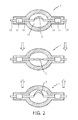
- FIG. 2 shows a simplified schematic representation of an arc-discharge lamp with a discharge-arc extending between two electrodes
- FIG. 3 shows a block diagram of a prior art lamp driver
- FIG. 4 shows a plot of experimentally obtained light modulation values against lamp modulation values and phase shift
- FIG. 5 shows a block diagram of a lamp driver according to an embodiment of the invention
- FIG. 6 shows simplified graphs of lamp voltage, lamp power and light output for a prior art lamp and a lamp driven using the method according to the invention
- FIG. 7 shows box-plots of light modulation for a lamp driven by a prior art method and by the method according to the invention
- FIG. 8 shows a schematic representation of a lighting assembly according to the invention.
- FIG. 1 shows an automobile front beam issued by a front headlamp of a vehicle.
- the region in which the perceptible and annoying forefront flicker originates is generally up to about 8 metres in front of the vehicle and in the beam region up to about 4° below a horizontal plane of the headlamp.
- FIG. 2 shows a simplified schematic representation of an arc-discharge lamp 1 with a discharge-arc 2 extending between two electrodes 10 .
- the discharge arc extends as shown between the two electrodes 10 .
- the discharge arc 2 is briefly ‘shortened’ as shown. This shorter discharge-arc is associated with a decrease in lamp voltage, and therefore also with a decrease in luminous flux.
- the discharge arc 2 is briefly ‘stretched’ as shown.
- FIG. 3 shows a simplified block diagram of a prior art lamp driver 30 , comprising a converter 5 for converting an input supply signal (for example from a car battery) to a level suitable for a lamp 1 , a commutation unit 6 (generally comprising a H-bridge for commutating the lamp current and an igniter for igniting the lamp).
- the driver 30 also comprises a voltage measurement unit 20 for monitoring the lamp voltage.
- the voltage measurement unit 20 forwards the lamp voltage values 21 to a power correction unit 8 , which interprets the lamp voltage values 21 to determine any required correction to the lamp current in order to maintain a constant lamp power.
- FIG. 4 shows a plot of experimentally obtained light modulation values (X-axis, in percent) against lamp modulation values (Z-axis, in percent) and phase shift (Y-axis, in degrees) for a lamp driven using a prior art lamp driver such as that described in FIG. 2 above.
- a lamp voltage modulation or fluctuation of about 1.0-1.5% results in a light output fluctuation of between 0.5% and 0.75%.
- the interesting aspect of this plot is that the fluctuation in light output clearly exhibits a distinct phase shift relative to the fluctuation or modulation in lamp voltage. An alteration in lamp voltage causes a corresponding increase or decrease in light output, but this is delayed relative to the lamp voltage alteration.
- This relationship is the basis for determining the power correction in the method according to the invention.
- measured lamp voltage values in the embodiment using a voltage measurement means
- Measured light output values in the embodiment using a light sensor
- Similar experimental results can be obtained for acceleration values correlated with lamp voltage fluctuations, so that measured values of acceleration (in the embodiment using an accelerometer) can be used to easily derive the required phase shift.
- the information thus gathered experimentally can be provided to the lamp driver in a suitable form, for example as a look-up table or as a simple algorithm for using the measured values to derive the required phase shift and amplitude for the power correction.
- FIG. 5 shows a block diagram of a lamp driver 3 according to an embodiment of the invention.
- the lamp driver 3 comprises a converter 5 and a commutation unit 6 .
- This lamp driver 3 also comprises a voltage measurement means 40 for obtaining lamp voltage values 41 .
- a lamp voltage modulation detector 41 which can be a simple envelope detector known to the skilled person, to provide a lamp voltage envelope 43 to an analysis unit 44 , which analyses the lamp voltage envelope 43 to determine a required phase shift and amplitude correction for the lamp power and to generate an appropriate power correction signal 45 for the power correction unit 8 .
- the analysis unit 42 can utilise a LUT or an algorithm for deriving the phase/amplitude correction on the basis of the relationship described in FIG. 4 above.
- the lamp driver 3 in addition to or as an alternative to the lamp voltage analysis, can analyse the light output of the lamp 1 .
- the lamp driver 3 comprises a light modulation detector 52 for processing measured lamp light values 51 delivered by a light sensor 50 , which can be placed close to the light source 1 or in the base of a lighting assembly or in any other suitable position.
- the light modulation detector 52 determines whether any fluctuation in light output is characteristic of a mechanically induced impact, and delivers appropriate power correction signals 53 to the power correction unit 8 .
- the lamp driver 3 can analyse a proper acceleration of the lamp 1 .
- the lamp driver 3 comprises a lamp vibration determination module 62 for processing measured lamp acceleration values 61 delivered by an accelerometer 60 .
- the lamp vibration determination module 62 determines a frequency of fluctuation in light output as a result of a sudden acceleration of the lamp, and delivers appropriate information 63 to an amplitude and phase adaptation unit 64 , which can use information stored in a LUT, for example, to determine a suitable phase shift and amplitude correction for the lamp power.
- the amplitude and phase adaptation unit 64 accordingly generates an appropriate power correction signal 65 for the power correction unit 8 .
- the lamp driver 3 is shown to include several analysis means.
- the lamp driver 3 can be realised to perform only lamp voltage analysis, only light output analysis, only acceleration analysis, or any combination of these techniques.
- the data processing steps such as lamp voltage analysis, light output analysis, acceleration analysis, phase shift and amplitude correction, etc., can be carried out by suitable software algorithms running on a microprocessor or microcontroller of the lamp driver 3 .
- FIG. 6 shows simplified graphs of modulated lamp voltage U, lamp power P, P C and modulated light output L, L C for a lamp driven using a prior art method and a lamp driven using the method according to the invention.
- the light output L for a lamp driven using a prior art method is shown.
- the discharge arc is disturbed and causes the lamp voltage to fluctuate.
- Values of lamp voltage measured at certain points during the lamp period show a fluctuation that can be graphed as the modulated lamp voltage U shown.
- the prior art lamp driver attempts to maintain a constant power P.
- the modulated light output L is shown to follow the modulated lamp voltage U by a time delay or phase shift.
- the modulated lamp voltage U is analysed to determine a lamp power correction.
- the corrected lamp power P C rapidly leads to a settling of the light output L C . In this way, a mechanically induced impact or a sudden change in velocity that causes the discharge arc to be disturbed will not be followed by a perceptible flicker in the forefront of the vehicle. Any flicker in the light output is suppressed so quickly that it may not be apparent to an observer.
- FIG. 7 shows box-plots of light modulation for a lamp driven by a prior art method (upper part of diagram) and for a lamp driven by the method according to the invention (lower part of diagram).
- An abrupt mechanically induced impact will alter the length of the discharge arc, leading to a fluctuation of the lamp voltage.
- the frequency components of the fluctuation will depend on the detailed ‘shape’ of the impact, since an impact or impulse can be expressed as the sum of its Fourier components.
- impacts to a headlamp were simulated by subjecting the headlamp to sinusoidal vibrations at different frequencies and a fixed amplitude. Depending on the actual nature of the impact, the various frequency components contribute to varying degrees to the voltage and light modulation.
- the higher the frequency the higher will be the modulation of the light flux.
- the light output is already modulated by over 0.4%.
- the light modulation increases to about 1.2%.
- the degree of modulation within this range of frequencies (indicated by the broken lines), with the associated perceptible flicker in the forefront of a vehicle, is easily perceptible to an observer and can be annoying and distracting, and therefore a safety hazard.
- the lamp driven using the method according to the invention can suppress the light output fluctuations to a level below which the flicker is essentially not perceptible.
- FIG. 8 shows a schematic representation of a lighting assembly 9 according to the invention.
- a lamp 1 is mounted on a lamp base 90 , in a reflector 91 and behind a projection lens 92 .
- Circuitry for the lamp driver 3 can be incorporated in the base 90 .
- the lighting assembly can include a light sensor 50 located in front of the lamp 1 or in the lamp base 90 (both positions are shown for clarity, but a single light sensor 50 is sufficient).
- the light assembly can include an accelerometer 60 located at a suitable position for detecting an acceleration of the lamp 1 .
- the driver may include an additional monitoring unit to track the lamp lifetime and make minor adjustments to the lamp power correction algorithm(s) used by the driver so that a lamp aging can be taken into account when correcting the lamp power.
- a unit or module can comprise other units or modules.
Landscapes
- Lighting Device Outwards From Vehicle And Optical Signal (AREA)
- Circuit Arrangements For Discharge Lamps (AREA)
Abstract
Description
Claims (14)
Applications Claiming Priority (4)
| Application Number | Priority Date | Filing Date | Title |
|---|---|---|---|
| EP10161405 | 2010-04-29 | ||
| EP10161405 | 2010-04-29 | ||
| EP10161405.5 | 2010-04-29 | ||
| PCT/IB2011/051742 WO2011135493A2 (en) | 2010-04-29 | 2011-04-21 | Method of driving an arc-discharge lamp |
Publications (2)
| Publication Number | Publication Date |
|---|---|
| US20130038220A1 US20130038220A1 (en) | 2013-02-14 |
| US9107276B2 true US9107276B2 (en) | 2015-08-11 |
Family
ID=44120299
Family Applications (1)
| Application Number | Title | Priority Date | Filing Date |
|---|---|---|---|
| US13/642,993 Expired - Fee Related US9107276B2 (en) | 2010-04-29 | 2011-04-21 | Method of driving an arc-discharge lamp |
Country Status (6)
| Country | Link |
|---|---|
| US (1) | US9107276B2 (en) |
| EP (1) | EP2564675B1 (en) |
| JP (1) | JP5873861B2 (en) |
| CN (1) | CN102860137B (en) |
| ES (1) | ES2474594T3 (en) |
| WO (1) | WO2011135493A2 (en) |
Families Citing this family (2)
| Publication number | Priority date | Publication date | Assignee | Title |
|---|---|---|---|---|
| US8159364B2 (en) * | 2007-06-14 | 2012-04-17 | Omnilectric, Inc. | Wireless power transmission system |
| US12352157B2 (en) * | 2022-11-18 | 2025-07-08 | Fmc Technologies, Inc. | In-riser tool operation monitored and verified through ROV |
Citations (15)
| Publication number | Priority date | Publication date | Assignee | Title |
|---|---|---|---|---|
| JPH02215090A (en) | 1989-02-16 | 1990-08-28 | Nissan Motor Co Ltd | Discharge lamp lighting device |
| JPH04342987A (en) | 1991-05-20 | 1992-11-30 | Toshiba Corp | Flicker suppressing device for fluorescent lamp of electric car |
| EP0713352A2 (en) | 1994-11-18 | 1996-05-22 | Matsushita Electric Industrial Co., Ltd. | Discharge lamp-lighting apparatus |
| EP0830982A2 (en) | 1996-07-19 | 1998-03-25 | Koito Manufacturing Co., Ltd. | Lighting circuit device for automobile |
| US5973457A (en) | 1997-05-15 | 1999-10-26 | Koito Manufacturing Co., Ltd. | Lighting circuit for discharge lamp |
| JP2004039563A (en) | 2002-07-05 | 2004-02-05 | Plus Vision Corp | Discharge lamp device having arc stabilizing function and projector using the same |
| US20040251852A1 (en) * | 2002-09-25 | 2004-12-16 | Takashi Kambara | Electronic ballast for a discharge lamp |
| US20050119796A1 (en) * | 2003-11-27 | 2005-06-02 | Adrian Steiner | Method and apparatus to control the rate of flow of a fluid through a conduit |
| WO2005064997A1 (en) | 2003-12-26 | 2005-07-14 | Matsushita Electric Works, Ltd. | Discharge lamp lighting apparatus and lamp system using the lighting apparatus |
| US20080088253A1 (en) | 2005-02-02 | 2008-04-17 | Patent-Treuhand-Gesellschaft Fur Elektrische Gluhlampen Mbh | Method for Operating a High-Pressure Discharge Lamp, Operating Appliance for a High-Pressure Discharge Lamp, and Illumination Device |
| JP2009093994A (en) | 2007-10-11 | 2009-04-30 | Iwasaki Electric Co Ltd | High pressure discharge lamp lighting device and projector |
| DE102007060035A1 (en) | 2007-12-05 | 2009-06-10 | Osram Gesellschaft mit beschränkter Haftung | High pressure discharge lamp i.e. mercury-free xenon-high pressure discharge lamp, operating method for automotive-application, supplies additional electrical power to high pressure discharge lamp based on detection of lamp flickers |
| WO2010100935A1 (en) | 2009-03-06 | 2010-09-10 | ハリソン東芝ライティング株式会社 | Vehicle discharge lamp, vehicle discharge lamp device, lighting circuit combined type vehicle discharge lamp device, and lighting circuit |
| FR2945246A1 (en) | 2009-05-05 | 2010-11-12 | Benedictus Haest | Light beam orientation stabilizing method for e.g. headlight of car, involves controlling linear actuator using corrected compensation signal for applying vibrations, which are opposite to response vibrations, to optical element |
| US20100289429A1 (en) * | 2006-08-10 | 2010-11-18 | Koninklijke Philips Electronics N.V. | Methods of and driving units for driving a gas discharge lamp |
Family Cites Families (3)
| Publication number | Priority date | Publication date | Assignee | Title |
|---|---|---|---|---|
| CN1149004C (en) * | 1899-12-30 | 2004-05-05 | 松下电器产业株式会社 | Ignitor for discharging lamp |
| JP3244859B2 (en) * | 1993-04-12 | 2002-01-07 | 池田デンソー株式会社 | Discharge lamp lighting device |
| US5569984A (en) * | 1994-12-28 | 1996-10-29 | Philips Electronics North America Corporation | Method and controller for detecting arc instabilities in gas discharge lamps |
-
2011
- 2011-04-21 CN CN201180021562.9A patent/CN102860137B/en not_active Expired - Fee Related
- 2011-04-21 ES ES11722901.3T patent/ES2474594T3/en active Active
- 2011-04-21 JP JP2013506782A patent/JP5873861B2/en not_active Expired - Fee Related
- 2011-04-21 US US13/642,993 patent/US9107276B2/en not_active Expired - Fee Related
- 2011-04-21 WO PCT/IB2011/051742 patent/WO2011135493A2/en not_active Ceased
- 2011-04-21 EP EP11722901.3A patent/EP2564675B1/en not_active Not-in-force
Patent Citations (15)
| Publication number | Priority date | Publication date | Assignee | Title |
|---|---|---|---|---|
| JPH02215090A (en) | 1989-02-16 | 1990-08-28 | Nissan Motor Co Ltd | Discharge lamp lighting device |
| JPH04342987A (en) | 1991-05-20 | 1992-11-30 | Toshiba Corp | Flicker suppressing device for fluorescent lamp of electric car |
| EP0713352A2 (en) | 1994-11-18 | 1996-05-22 | Matsushita Electric Industrial Co., Ltd. | Discharge lamp-lighting apparatus |
| EP0830982A2 (en) | 1996-07-19 | 1998-03-25 | Koito Manufacturing Co., Ltd. | Lighting circuit device for automobile |
| US5973457A (en) | 1997-05-15 | 1999-10-26 | Koito Manufacturing Co., Ltd. | Lighting circuit for discharge lamp |
| JP2004039563A (en) | 2002-07-05 | 2004-02-05 | Plus Vision Corp | Discharge lamp device having arc stabilizing function and projector using the same |
| US20040251852A1 (en) * | 2002-09-25 | 2004-12-16 | Takashi Kambara | Electronic ballast for a discharge lamp |
| US20050119796A1 (en) * | 2003-11-27 | 2005-06-02 | Adrian Steiner | Method and apparatus to control the rate of flow of a fluid through a conduit |
| WO2005064997A1 (en) | 2003-12-26 | 2005-07-14 | Matsushita Electric Works, Ltd. | Discharge lamp lighting apparatus and lamp system using the lighting apparatus |
| US20080088253A1 (en) | 2005-02-02 | 2008-04-17 | Patent-Treuhand-Gesellschaft Fur Elektrische Gluhlampen Mbh | Method for Operating a High-Pressure Discharge Lamp, Operating Appliance for a High-Pressure Discharge Lamp, and Illumination Device |
| US20100289429A1 (en) * | 2006-08-10 | 2010-11-18 | Koninklijke Philips Electronics N.V. | Methods of and driving units for driving a gas discharge lamp |
| JP2009093994A (en) | 2007-10-11 | 2009-04-30 | Iwasaki Electric Co Ltd | High pressure discharge lamp lighting device and projector |
| DE102007060035A1 (en) | 2007-12-05 | 2009-06-10 | Osram Gesellschaft mit beschränkter Haftung | High pressure discharge lamp i.e. mercury-free xenon-high pressure discharge lamp, operating method for automotive-application, supplies additional electrical power to high pressure discharge lamp based on detection of lamp flickers |
| WO2010100935A1 (en) | 2009-03-06 | 2010-09-10 | ハリソン東芝ライティング株式会社 | Vehicle discharge lamp, vehicle discharge lamp device, lighting circuit combined type vehicle discharge lamp device, and lighting circuit |
| FR2945246A1 (en) | 2009-05-05 | 2010-11-12 | Benedictus Haest | Light beam orientation stabilizing method for e.g. headlight of car, involves controlling linear actuator using corrected compensation signal for applying vibrations, which are opposite to response vibrations, to optical element |
Also Published As
| Publication number | Publication date |
|---|---|
| JP5873861B2 (en) | 2016-03-01 |
| WO2011135493A3 (en) | 2011-12-22 |
| ES2474594T3 (en) | 2014-07-09 |
| US20130038220A1 (en) | 2013-02-14 |
| EP2564675B1 (en) | 2014-05-14 |
| EP2564675A2 (en) | 2013-03-06 |
| CN102860137A (en) | 2013-01-02 |
| JP2013525987A (en) | 2013-06-20 |
| CN102860137B (en) | 2015-02-11 |
| WO2011135493A2 (en) | 2011-11-03 |
Similar Documents
| Publication | Publication Date | Title |
|---|---|---|
| JP4561097B2 (en) | Discharge lamp lighting device and lighting device | |
| US10099602B2 (en) | Vehicle lamp having a predetermined light distribution pattern | |
| US9736585B2 (en) | System and method for driving a low frequency speaker | |
| US9107276B2 (en) | Method of driving an arc-discharge lamp | |
| KR20030011622A (en) | Electronic circuit for operating a hid lamp, and image projector | |
| KR20130135761A (en) | Discharge lamp lighting device, automotive high-intensity discharge lamp lighting device, automotive headlight device, and car | |
| JP2017106977A (en) | projector | |
| KR100294371B1 (en) | Discharge lamp lighting device and method | |
| US10222684B2 (en) | Projector and control method for projector | |
| CN103141161B (en) | For control and the adjusting device of the gaseous discharge lamp of automotive headlight | |
| JP2004341445A (en) | Image projection device | |
| US20100026210A1 (en) | Apparatus for driving a gas discharge lamp | |
| ES2276654T3 (en) | PROCEDURE AND DEVICE FOR THE REGULATION OF THE LIGHTING DISTANCE OF A CAR. | |
| US20190361237A1 (en) | Head-up display device | |
| JP2013516727A (en) | Device for driving a gas discharge lamp | |
| JP2011521409A (en) | Driving method of UHP gas discharge lamp | |
| JP2008529245A (en) | High pressure discharge lamp operating method, high pressure discharge lamp operating device and lighting device | |
| JP6916271B2 (en) | Automotive headlamps with low beam lift | |
| US20100033098A1 (en) | Method and device for driving a gas discharge lamp | |
| KR101500396B1 (en) | Vehichle generator control system and method | |
| KR102484863B1 (en) | Method for correcting vibration by lighting control wiring of cluster and avn and lighting vibaration correction device using the same | |
| JP2013126816A (en) | Vehicle lamp | |
| JP2009071954A (en) | Control method for electric fan for vehicle and control device for electric fan for vehicle | |
| JP5778587B2 (en) | Optical head adjusting device for vehicle headlamps, vehicle headlamp system | |
| KR101003956B1 (en) | Ground separation type laser device with signal extraction device for output and wavelength stabilization |
Legal Events
| Date | Code | Title | Description |
|---|---|---|---|
| AS | Assignment |
Owner name: KONINKLIJKE PHILIPS ELECTRONICS N.V., NETHERLANDS Free format text: ASSIGNMENT OF ASSIGNORS INTEREST;ASSIGNORS:RIEDERER, XAVER;DABRINGHAUSEN, LARS;SIGNING DATES FROM 20120117 TO 20120118;REEL/FRAME:029177/0205 |
|
| ZAAA | Notice of allowance and fees due |
Free format text: ORIGINAL CODE: NOA |
|
| ZAAB | Notice of allowance mailed |
Free format text: ORIGINAL CODE: MN/=. |
|
| AS | Assignment |
Owner name: KONINKLIJKE PHILIPS N.V., NETHERLANDS Free format text: CHANGE OF NAME;ASSIGNOR:KONINKLIJKE PHILIPS ELECTRONICS N.V.;REEL/FRAME:036115/0538 Effective date: 20130515 |
|
| STCF | Information on status: patent grant |
Free format text: PATENTED CASE |
|
| AS | Assignment |
Owner name: DEUTSCHE BANK AG NEW YORK BRANCH, AS COLLATERAL AGENT, NEW YORK Free format text: SECURITY INTEREST;ASSIGNOR:LUMILEDS LLC;REEL/FRAME:043108/0001 Effective date: 20170630 Owner name: DEUTSCHE BANK AG NEW YORK BRANCH, AS COLLATERAL AG Free format text: SECURITY INTEREST;ASSIGNOR:LUMILEDS LLC;REEL/FRAME:043108/0001 Effective date: 20170630 |
|
| AS | Assignment |
Owner name: LUMILEDS LLC, CALIFORNIA Free format text: ASSIGNMENT OF ASSIGNORS INTEREST;ASSIGNOR:KONINKLIJKE PHILIPS N.V.;REEL/FRAME:044809/0940 Effective date: 20170428 |
|
| MAFP | Maintenance fee payment |
Free format text: PAYMENT OF MAINTENANCE FEE, 4TH YEAR, LARGE ENTITY (ORIGINAL EVENT CODE: M1551); ENTITY STATUS OF PATENT OWNER: LARGE ENTITY Year of fee payment: 4 |
|
| AS | Assignment |
Owner name: SOUND POINT AGENCY LLC, NEW YORK Free format text: SECURITY INTEREST;ASSIGNORS:LUMILEDS LLC;LUMILEDS HOLDING B.V.;REEL/FRAME:062299/0338 Effective date: 20221230 |
|
| FEPP | Fee payment procedure |
Free format text: MAINTENANCE FEE REMINDER MAILED (ORIGINAL EVENT CODE: REM.); ENTITY STATUS OF PATENT OWNER: LARGE ENTITY |
|
| LAPS | Lapse for failure to pay maintenance fees |
Free format text: PATENT EXPIRED FOR FAILURE TO PAY MAINTENANCE FEES (ORIGINAL EVENT CODE: EXP.); ENTITY STATUS OF PATENT OWNER: LARGE ENTITY |
|
| STCH | Information on status: patent discontinuation |
Free format text: PATENT EXPIRED DUE TO NONPAYMENT OF MAINTENANCE FEES UNDER 37 CFR 1.362 |
|
| FP | Lapsed due to failure to pay maintenance fee |
Effective date: 20230811 |
|
| AS | Assignment |
Owner name: LUMILEDS HOLDING B.V., NETHERLANDS Free format text: RELEASE BY SECURED PARTY;ASSIGNOR:SOUND POINT AGENCY LLC;REEL/FRAME:070046/0001 Effective date: 20240731 Owner name: LUMILEDS LLC, CALIFORNIA Free format text: RELEASE BY SECURED PARTY;ASSIGNOR:SOUND POINT AGENCY LLC;REEL/FRAME:070046/0001 Effective date: 20240731 Owner name: LUMILEDS LLC, CALIFORNIA Free format text: RELEASE OF SECURITY INTEREST;ASSIGNOR:SOUND POINT AGENCY LLC;REEL/FRAME:070046/0001 Effective date: 20240731 Owner name: LUMILEDS HOLDING B.V., NETHERLANDS Free format text: RELEASE OF SECURITY INTEREST;ASSIGNOR:SOUND POINT AGENCY LLC;REEL/FRAME:070046/0001 Effective date: 20240731 |