US9106303B2 - Relay and method for performing network coding - Google Patents
Relay and method for performing network coding Download PDFInfo
- Publication number
- US9106303B2 US9106303B2 US13/495,448 US201213495448A US9106303B2 US 9106303 B2 US9106303 B2 US 9106303B2 US 201213495448 A US201213495448 A US 201213495448A US 9106303 B2 US9106303 B2 US 9106303B2
- Authority
- US
- United States
- Prior art keywords
- transmit
- receive pairs
- relay
- receive
- pairs
- Prior art date
- Legal status (The legal status is an assumption and is not a legal conclusion. Google has not performed a legal analysis and makes no representation as to the accuracy of the status listed.)
- Expired - Fee Related, expires
Links
Images


Classifications
-
- H—ELECTRICITY
- H04—ELECTRIC COMMUNICATION TECHNIQUE
- H04B—TRANSMISSION
- H04B7/00—Radio transmission systems, i.e. using radiation field
- H04B7/14—Relay systems
- H04B7/15—Active relay systems
- H04B7/155—Ground-based stations
- H04B7/15521—Ground-based stations combining by calculations packets received from different stations before transmitting the combined packets as part of network coding
-
- H—ELECTRICITY
- H04—ELECTRIC COMMUNICATION TECHNIQUE
- H04B—TRANSMISSION
- H04B7/00—Radio transmission systems, i.e. using radiation field
- H04B7/02—Diversity systems; Multi-antenna system, i.e. transmission or reception using multiple antennas
- H04B7/04—Diversity systems; Multi-antenna system, i.e. transmission or reception using multiple antennas using two or more spaced independent antennas
- H04B7/06—Diversity systems; Multi-antenna system, i.e. transmission or reception using multiple antennas using two or more spaced independent antennas at the transmitting station
- H04B7/0613—Diversity systems; Multi-antenna system, i.e. transmission or reception using multiple antennas using two or more spaced independent antennas at the transmitting station using simultaneous transmission
- H04B7/0615—Diversity systems; Multi-antenna system, i.e. transmission or reception using multiple antennas using two or more spaced independent antennas at the transmitting station using simultaneous transmission of weighted versions of same signal
- H04B7/0617—Diversity systems; Multi-antenna system, i.e. transmission or reception using multiple antennas using two or more spaced independent antennas at the transmitting station using simultaneous transmission of weighted versions of same signal for beam forming
-
- H—ELECTRICITY
- H04—ELECTRIC COMMUNICATION TECHNIQUE
- H04B—TRANSMISSION
- H04B7/00—Radio transmission systems, i.e. using radiation field
- H04B7/02—Diversity systems; Multi-antenna system, i.e. transmission or reception using multiple antennas
- H04B7/04—Diversity systems; Multi-antenna system, i.e. transmission or reception using multiple antennas using two or more spaced independent antennas
- H04B7/08—Diversity systems; Multi-antenna system, i.e. transmission or reception using multiple antennas using two or more spaced independent antennas at the receiving station
- H04B7/0837—Diversity systems; Multi-antenna system, i.e. transmission or reception using multiple antennas using two or more spaced independent antennas at the receiving station using pre-detection combining
- H04B7/0842—Weighted combining
- H04B7/086—Weighted combining using weights depending on external parameters, e.g. direction of arrival [DOA], predetermined weights or beamforming
Definitions
- the following description relates to a relay and method that performs network coding.
- Communication systems are used to connect a user to another user to perform voice, video, and text communication. It is estimated that at least one percent of all devices around the world may be connected to each other over a network. As communication technologies continue to increase, a larger network is expected to be established. These communication technologies include smart phones, sensor devices, and other varied devices having different functions.
- D2D device-to-device
- a method of performing network coding in a network including K transmit-and-receive pairs and a relay including M antennas, each terminal included in the K transmit-and-receive pairs including N antennas, the method including determining transmission beamforming vectors for the terminals included in the K transmit-and-receive pairs so that effective channels from the K transmit-and-receive pairs to the relay are aligned in independent dimensions, in response to the K transmit-and-receive pairs simultaneously transmitting signals, detecting the signals transmitted from the K transmit-and-receive pairs using the effective channels aligned in the independent dimensions, determining reception beamforming vectors for the terminals included in the K transmit-and-receive pairs so that the effective channels of the terminals included in the K transmit-and-receive pairs are aligned in the same dimension, and simultaneously transmitting network-coded signals for the K transmit-and-receive pairs, the network-coded signals being generated based on the detected signals.
- M corresponding to a number of the antennas included in the relay may be greater than or equal to K corresponding to a number of the transmit-and-receive pairs, and M may be less than 2N corresponding to twice the number of antennas of each terminal included in the K transmit-and-receive pairs.
- the relay may determine the transmission beamforming vectors in a first time slot, and perform network coding that determines the reception beamforming vectors in a second time slot.
- Signals among terminals included in one of the K transmit-and-receive pairs may be aligned in the same dimension.
- the method may further comprise separating remaining transmit-and-receive pairs from one of the K transmit-and-receive pairs such that the remaining transmit-and-receive pairs are in different dimensions from the one transmit-and-receive pair.
- the determining of the reception beamforming vectors of the terminals included in the K transmit-and-receive pairs may be based on an assumption that the effective channels obtained by applying the reception beamforming vectors to the terminals included in the K transmit-and-receive pairs are the same.
- the terminals included in one of the K transmit-and-receive pairs may receive signals that are equivalently network-coded.
- a computer-readable storage medium having stored therein program instructions to cause a processor to execute method of performing network coding in a network including K transmit-and-receive pairs and a relay including M antennas, each terminal included in the K transmit-and-receive pairs including N antennas, the method including determining transmission beamforming vectors for the terminals included in the K transmit-and-receive pairs so that effective channels from the K transmit-and-receive pairs to the relay are aligned in independent dimensions, in response to the K transmit-and-receive pairs simultaneously transmitting signals, detecting the signals transmitted from the K transmit-and-receive pairs using the effective channels aligned in the independent dimensions, determining reception beamforming vectors for the terminals included in the K transmit-and-receive pairs so that the effective channels of the terminals included in the K transmit-and-receive pairs are aligned in the same dimension, and simultaneously transmitting network-coded signals for the K transmit-and-receive pairs, the network-coded signals being generated
- a relay including M antennas that performs network coding in a network including K transmit-and-receive pairs, each terminal included in the K transmit-and-receive pairs including N antennas, the relay including a transmission beamforming vector determining unit configured to determine transmission beamforming vectors for the terminals included in the K transmit-and-receive pairs so that effective channels from the K transmit-and-receive pairs to the relay are aligned in independent dimensions, in response to the K transmit-and-receive pairs simultaneously transmitting signals, a detector configured to detect the signals transmitted from the K transmit-and-receive pairs, using the effective channels aligned in the independent dimensions, a reception beamforming vector determining unit configured to determine reception beamforming vectors for the terminals included in the K transmit-and-receive pairs so that the effective channels of the terminals included in the K transmit-and-receive pairs are aligned in the same dimension, and a transmitter configured to transmit network-coded signals for the K transmit-and-receive pairs simultaneously,
- M corresponding to a number of the antennas included in the relay may be greater than or equal to K corresponding to a number of the transmit-and-receive pairs, and M may be less than 2N corresponding to twice the number of antennas of each terminal included in the K transmit-and-receive pairs.
- the relay may be configured to determine the transmission beamforming vectors in a first time slot, and perform network coding that determines the reception beamforming vectors in a second time slot.
- the signals among terminals included in one of the K transmit-and-receive pairs may be aligned in the same dimension.
- the relay may further comprise a separator configured to separate remaining transmit-and-receive pairs excluding one of the K transmit-and-receive pairs from the one excluded transmit-and-receive pair so as to be in different dimensions from the one excluded transmit-and-receive pair.
- the reception beamforming vector determining unit may be configured to determine the reception beamforming vectors of the terminals included in the K transmit-and-receive pairs based on an assumption that the effective channels obtained by applying the reception beamforming vectors to the terminals included in the K transmit-and-receive pairs are the same.
- the terminals included in one of the transmit-and-receive pairs may be configured to receive signals that are equivalently network-coded.
- a relay in a network including a plurality of transmit-and-receive pairs, the relay including a transmission beamforming unit configured to determine transmission beamforming vectors for the plurality of transmit-and-receive pairs so that channels from each pair of the plurality of transmit-and-receive pairs to the relay are aligned in independent dimensions, and a detector configured to detect transmission signals from the plurality of transmit-and-receive pairs via the channels aligned in independent dimensions.
- the detector may be configured to simultaneously detect a transmission signal and a reception signal from each transmit-and-receive pair, from among the plurality of transmit-and-receive pairs.
- the transmission beamforming unit may be configured to align the transmission signal and the reception signal from each transmit-and-receive pair into a dimension that is different from the dimensions of the transmission signals and the receptions signals of the other transmit-and-receive pairs.
- the relay may further comprise a reception beamforming unit configured to determine reception beamforming vectors for the plurality of transmit-and-receive pairs based on the detected signals so that channels from the relay to each of the plurality of transmit-and-receive pairs are aligned in independent dimensions.
- a reception beamforming unit configured to determine reception beamforming vectors for the plurality of transmit-and-receive pairs based on the detected signals so that channels from the relay to each of the plurality of transmit-and-receive pairs are aligned in independent dimensions.
- the relay may further comprise a transmitter configured to simultaneously transmit the signals to the plurality of transmit-and-receive pairs via the channels aligned in independent dimensions.
- FIG. 1 is a diagram illustrating an example of a network environment including a plurality of transmit-and-receive pairs and a relay including a plurality of antennas.
- FIG. 2 is a diagram illustrating an example of a method of grouping terminals into a plurality of transmit-and-receive pairs in a network of FIG. 1 .
- FIG. 3 is a flowchart illustrating an example of a method of performing network coding in a network including a plurality of transmit-and-receive pairs and a relay including a plurality of antennas.
- FIG. 4 is a diagram illustrating an example of a method of determining transmission beamforming vectors of terminals included in a plurality of transmit-and-receive pairs in a first phase for network coding.
- FIG. 5 is a diagram illustrating an example of a method of determining reception beamforming vectors of terminals included in a plurality of transmit-and-receive pairs in a second phase for network coding.
- FIG. 6 is a diagram illustrating an example of a relay that performs network coding in a network including a plurality of transmit-and-receive pairs and a relay including a plurality of antennas.
- a transmission signal refers to a signal that may be transmitted from a transmission node
- a reception signal refers to a signal that may be transmitted from a reception node.
- An example of a node is a terminal, such as a smart phone, a computer, a tablet, an appliance, a sensor, and the like.
- FIG. 1 illustrates an example of a network environment including a plurality of transmit-and-receive pairs and a relay including a plurality of antennas.
- the plurality of transmit-and-receive pairs may perform network coding for a multi-pair two way relay channel.
- a two-way relay channel may refer to a channel through which two terminals or users exchange data using a relay.
- the multi-pair two-way relay channel may refer to two-way relay channels that are formed by a plurality of nodes.
- Example schemes to perform data transmission via the multi-pair two-way relay channel is a decoding & forward and an amplified & forward scheme which has been used in a conventional one-way relay.
- a network capacity that is, a transmission capacity of a network
- a transmission capacity of a network may be inversely proportional to a number of time slots. Therefore, the transmission capacity of the network may be reduced in inverse proportion to the number of users. That is, the more users the less transmission capacity available on the network.
- the decrease in the transmission capacity may occur because different resources, for example, different time slots, are used for each transmission, as opposed to using an appropriate interference management scheme.
- a time slot may decrease to half the time slot.
- the unit-pair may divide the other resources with other pairs, and thus, six time slots may be expanded in the two-way relay of the unit-pair.
- the six time slots may be used because the transmission capacity of the network may decrease to be inversely proportional to the number of the terminals or users. Accordingly, if the number of terminals or users increases rapidly, a serious drawback may occur due to a decrease in the transmission efficiency in the network.
- a beamforming vector that enables transmission and receptions pairs to share resources in a relay having a plurality of antennas may be designed so that the transmission capacity of the network is not inversely proportional to the number of terminals.
- a network 100 may include six terminals, that is, a first terminal 101 , a second terminal 103 , a third terminal 105 , a fourth terminal 107 , a fifth terminal 109 , and a sixth terminal 111 .
- the first terminal 101 may exchange a signal or data with the fourth terminal 107
- the second terminal 103 may exchange a signal or data with the fifth terminal 109
- the third terminal 105 may exchange a signal or data with the sixth terminal 111 .
- three transmit-and-receive pairs exist.
- a number of antennas (N) of each terminal included in the transmit-and-receive pairs is two.
- the three transmit-and-receive pairs may simultaneously exchange data through a relay.
- a number of antennas (M) included in the relay is assumed to be three.
- straight lines connected between the relay and each terminal denote signals
- dotted lines connected between the relay and each terminal denote interference.
- the relay may perform grouping for terminals that perform signal transmission and reception with each other, as shown in FIG. 2 , so as to simultaneously exchange multiple two-way data.
- FIG. 2 illustrates an example of a method of grouping terminals into plurality of transmit-and-receive pairs.
- a plurality of transmit-and-receive pairs may simultaneously exchange signals using a single relay, as illustrated in FIG. 1 .
- the relay may group the terminals into the plurality of transmit-and-receive pairs, and may simultaneously exchange multiple two-way data via a multi-pair two-way relay channel during two time slots.
- different nodes may correspond to different terminals or users, and nodes that have the same pattern may denote a transmit-and-receive pair that performs transmission and reception of data or a signal with each other.
- the relay may simultaneously receive two signals, that is, a transmission signal and a reception signal, in a first phase.
- the first phase may be a medium access control (MAC) phase.
- the relay that simultaneously receives the two signals from different terminals may perform grouping of the signals as a transmission signal and a corresponding reception signal, to configure a transmit-and-receive pair.
- a current physical-layer network coding scheme may not process three or more signals that enter simultaneously. Accordingly, three or more signals may not be entered in the same dimension in the multi-pair two-way relay.
- the relay may use at least three independent dimensions. If three independent dimensions are secured, the relay may align the signals transmitted from the three transmit-and-receive pairs in the independent dimensions. The relay may determine transmission beamforming vectors so that the signals transmitted from the transmit-and-receive pairs are aligned in the independent dimensions.
- a scheme that aligns different signals transmitted from respective transmit-and-receive pairs in independent dimensions may be referred to as a signal alignment scheme.
- the relay may determine reception beamforming vectors so that effective channels of terminals included in a single transmit-and-receive pair are aligned in the same dimension in a second phase.
- the second phase may be a broadcasting phase.
- a scheme that aligns effective channels in the same dimension may be referred to as a channel alignment scheme.
- the effective channels may be obtained by applying the reception beamforming vectors to two terminals included in a single transmit-and-receive pair.
- two signals of the two terminals that are aligned in the same dimension may be grouped as a single user group, that is, a single transmit-and-receive pair.
- the described schemes may be applied to a coordinated beamforming so that a plurality of transmit-and-receive pairs may quickly exchange data using a single relay having a plurality of transmit-and-receive antennas.
- a method of determining transmission beamforming vectors and reception beamforming vectors according to a network coding method may be applied to an example in which a plurality of user pairs in a cell exchange data using a base station in a cellular system and to an example in which a plurality of user pairs in an ad hoc network exchanges data using an access point (AP), a mobile relay, and the like.
- AP access point
- FIG. 3 illustrates an example of a method of performing network coding in a network including a plurality of transmit-and-receive pairs and a relay including a plurality of antennas.
- An example of a method of a relay performing network coding in a network including K transmit-and-receive pairs and a relay including M antennas, is provided.
- each terminal included in the K transmit-and-receive pairs includes N antennas.
- the relay performs grouping.
- the relay may group a plurality of transmission nodes and a plurality of reception nodes that exchange data with each other in a network into the K transmit-and-receive pairs.
- the relay determines transmission beamforming vectors. For example, for the K transmit-and-receive pairs that transmit signals simultaneously, the relay may determine transmission beamforming vectors for terminals included in the K transmit-and-receive pairs, in 303 , so that effective channels from the K transmit-and-receive pairs to the relay may be aligned in independent dimensions, respectively. As an example, the relay may determine transmission beamforming vectors according to Equation 2 that is further described with respect to FIG. 4 .
- signals between terminals included in one of the K transmit-and-receive pairs may be aligned in the same dimension.
- terminal 1 101 and terminal 4 107 may form a single transmit-and-receive pair, and signals between the terminal 1 101 and the terminal 4 107 may be aligned in the same dimension, for example, an X dimension.
- the relay may separate the other remaining transmit-and-receive pairs excluding one of the K transmit-and-receive pairs so that the remaining transmit-and-receive pairs are in different dimensions from the one excluded transmit-and-receive pair.
- antennas of each device included in a network may be configured to perform network coding.
- a number of antennas (M) included in the relay may be greater than or equal to K corresponding to a number of transmit-and-receive pairs, and less than 2N corresponding to a number of antennas included in each terminal of the transmit-and-receive pairs.
- a condition for a signal alignment scheme may be that M corresponding to the number of antennas included in the relay is less than 2N corresponding to the number of antennas of each terminal included in the transmit-and-receive pairs.
- a condition for obtaining independent dimensions for the transmit-and-receive pairs may be that M corresponding to the number of antennas included in the relay is greater than or equal to K corresponding to the number of transmit-and-receive pairs.
- the relay detects signals transmitted by the K transmit-and-receive pairs, using the effective channels respectively aligned in independent dimensions.
- the relay determines reception beamforming vectors for the terminals included in the K transmit-and-receive pairs, so that the effective channels of the terminals included in the K transmit-and-receive pairs are aligned in the same dimension.
- the reception beamforming vectors of the terminals included in the K transmit-and-receive pairs may be determined.
- An example of a method of the relay determining a reception beamforming vector is described with reference to FIG. 5 .
- the relay simultaneously transmits network-coded signals, which are generated based on the detected signals, for the K transmit-and-receive pairs.
- terminals included in one of the K transmit-and-receive pairs may receive signals that are equivalently network coded.
- the network coding may include network coding in a physical layer, and an analog network coding.
- the relay may determine the transmission beamforming vectors during a first time slot, and may determine the reception beamforming vectors during a second time slot, so as to transmit network coded signals for the K transmit-and-receive pairs, simultaneously. Accordingly, the relay may simultaneously exchange multiple two-way data transmission during using only two-time slots.
- FIG. 4 illustrates an example of a method of determining transmission beamforming vectors of terminals included in a plurality of transmit-and-receive pairs in a first phase for network coding.
- a relay 420 may receive the two signals, simultaneously, at a first phase. This first phase may be referred to as a MAC phase.
- the relay 420 may receive a transmission signal S 1 of a first terminal 401 and a reception signal S 4 of a fourth terminal 407 , may receive a transmission signal S 2 of a second terminal 403 and a reception signal S 5 of a fifth terminal 409 , and may receive a transmission signal S 3 of a third terminal 405 and a reception signal S 6 of a sixth terminal 411 , simultaneously.
- H ri denotes a channel from an i th terminal included in K transmit-and-receive pairs to a relay
- V i denotes a transmission beamforming vector of the i th terminal.
- H rk denotes a channel from a k th terminal included in the K transmit-and-receive pair to the relay
- V k denotes a transmission beamforming vector of the k th terminal.
- Span (•) denotes a space in which a column vector of a corresponding matrix is spanned.
- H ri is a square matrix, and thus, may be spanned in any direction.
- a result of spanning a channel from the first terminal 401 to the relay 420 and a transmission beamforming vector of the first terminal 401 may be equal to a result of spanning a channel from the fourth terminal 407 to the relay 420 and a beamforming vector of the fourth terminal 407 . That is, in this example a signal of the first terminal 401 and a signal of the fourth terminal 407 may exist in the same dimension.
- a beamforming vector satisfying Equation 1 may be calculated based on Equation 2.
- I M denotes an identity matrix
- H ri denotes a channel from an i th terminal included in the K transmit-and-receive pairs to a relay
- v i denotes a transmission beamforming vector of the i th terminal.
- h i align denotes a direction of alignment of each effective channel including a transmission beamforming vector.
- ⁇ tilde over (v) ⁇ i denotes an effective transmission signal of the i th terminal that is obtained based on a product of a transmission signal and the transmission beam forming vector of the i th terminal
- ⁇ tilde over (v) ⁇ k denotes an effective transmission signal of the k th terminal that is obtained based on a product of a transmission signal and the transmission beamforming vector of the k th terminal.
- the relay 420 may design a transmission beamforming vector that satisfies the condition.
- the condition may include a condition that signals between terminals included in one of transmit-and-receive pairs may be aligned in the same dimension, and effective channels from K transmit-and-receive pairs to the relay 420 are aligned in independent dimensions.
- Equation 2 when a number of rows is less than a number of columns in M i , a null space exists, and thus, at least one X i may exist. Because M i has 6 ⁇ 7 dimensions in Equation 2, a null space of one dimension exists and thus, one X i satisfying Equation 2 may exist.
- Equation 3 a condition that allows satisfying Equation 2 may be expressed by Equation 3 and Equation 4. 2 M ⁇ M+ 2 N [Equation 3] M ⁇ K [Equation 4]
- Equation 3 is an example of a condition for signal alignment
- Equation 4 is an example of a condition for obtaining an independent dimension for each transmit-and-receive pair.
- a range of M corresponding to the number of antennas included in the relay 420 may be expressed by Equation 5, based on Equation 3 and Equation 4.
- the relay 420 may utilize a signal alignment scheme. K ⁇ M ⁇ 2 N [Equation 5]
- the relay 420 may calculate transmission beamforming vectors to be used by terminals included in the transmit-and-receive pairs, in an MAC phase. In this example, if the terminals included in the transmit-and-receive pairs simultaneously transmit signals using the transmission beamforming vectors, the relay 420 may receive a signal 430 as shown in FIG. 4 .
- the relay 420 may detect K signals included in independent dimensions using the reception beamforming vectors for the K signals, in the first phase.
- K is three.
- a reception beamforming vector u i for K signals included in independent dimensions may be calculated based on a zero-forcing beamforming scheme, as given in Equation 6.
- u i null([ h 1 align . . . h i ⁇ 1 align h i+1 align . . . h K align ]) [Equation 6]
- null(A) denotes a normalized vector corresponding to a null space of a matrix A.
- the relay 420 may determine the reception beamforming vector u i to enable effective channels of the terminals to be null as expressed by Equation 6.
- the relay 420 may separate independent dimensions so as to utilize a network coding scheme used in a two-way relay channel.
- FIG. 5 illustrates an example of a method of determining reception beamforming vectors of terminals included in a plurality of transmit-and-receive pairs in a second phase for network coding.
- the second phase may be, for example, a broadcasting phase.
- a reception beamforming vector of a terminal may be determined so that corresponding terminals included in transmit-and-receive pairs are able to receive K network-coded signals obtained in a first phase.
- a reception beamforming vector recognized through a broadcasting channel may be, for example, a distribution of power control (DPC) vector, a zero-forcing vector, and the like.
- DPC distribution of power control
- the number of antennas of the relay 520 may be in a range of K ⁇ M ⁇ 2N. That is, the number of antennas included in the relay 520 may be greater than or equal to K corresponding to a number of transmit-and-receive pairs, and less than 2N corresponding to a number of antennas of each terminal included in transmit-and-receive pairs. Accordingly, it may be difficult to transmit a desired signal to a user using the reception beamforming vector recognized through the broadcasting channel.
- the terminals included in the transmit-and-receive pairs use a characteristic that receives signals that are equivalently network coded.
- the terminals that receive the equivalently network coded signals may be grouped into a single user group in the second phase. For example, a first terminal 501 and a fourth terminal 507 included in a single user group may receive the equivalently network coded signals.
- M corresponding to the number of antennas of the relay 520 is less than 2K corresponding to a number of terminals included in a network
- transmission may be performed.
- the relay 520 may regard channels between two terminals as the same channel. Therefore, different data may be transmitted to K users.
- the relay 520 may determine the reception beamforming vectors of the terminals included in the K transmit-and-receive pairs, respectively.
- channel alignment scheme An example of a scheme that aligns different effective channels in the same dimension may be referred to as a channel alignment scheme.
- the channel alignment may be expressed as given in Equation 7, similar to the signal alignment performed in the first phase.
- Equation 7 h i align denotes a direction of alignment for effective channels including the reception beamforming vectors. Also, ⁇ i denotes an effective reception signal of an i th terminal obtained by a product of a reception signal and a reception beamforming vector of the i th terminal, and ⁇ k denotes an effective reception signal of a k th terminal obtained by a product of a reception signal and a reception beamforming vector of the k th terminal.
- signals may be transmitted to desired terminals through the channel alignment in the second phase.
- the transmit-and-receive pairs such as a pair of the first terminal 501 and the fourth terminal 507 , a pair of the second terminal 503 and a fifth terminal 509 , and a pair of the third terminal 505 and the sixth terminal 511 , may receive equivalently network coded signals through reception beamforming vectors determined by the relay 520 .
- the first terminal 501 may receive a reception signal S 4
- the fourth terminal 507 may receive a reception signal S 1
- the second terminal 503 may receive a reception signal S 5
- the fifth terminal 509 may receive a reception signal S 2
- the third terminal 505 may receive a reception signal S 6
- the sixth terminal 511 may receive a reception signal S 3 , simultaneously.
- each terminal may receive a desired signal through self-interference.
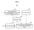
- FIG. 6 illustrates an example of a relay that performs network coding in a network including a plurality of transmit-and-receive pairs and a relay including a plurality of antennas
- relay 600 that performs network coding includes a transmission beamforming vector determining unit 601 , a detector 603 , a reception beamforming vector determining unit 605 , and a transmitter 607 . Also, the relay 600 may additionally include a separator 609 . The relay 600 also includes a receiver (not shown).
- the network may include K transmit-and-receive pairs and a relay may include M antennas, and each terminal included in the K transmit-and-receive pairs may include N antennas.
- M corresponding to the number of antennas included in the relay 600 may be greater than or equal to K corresponding to the number of transmit-and-receive pairs, and less than 2N corresponding to a number of antennas of each terminal included in the transmit-and-receive pairs.
- the transmission beamforming vector determining unit 601 may determine transmission beamforming vectors for the terminals included in the K transmit-and-receive pairs so as to align effective channels from the K transmit-and-receive pairs to the relay 600 in independent dimensions, respectively.
- signals between terminals included in one of the K transmit-and-receive pairs may be aligned in the same dimension.
- the detector 603 may detect signals transmitted from the K transmit-and-receive pairs, using effective channels aligned in the independent dimensions.
- the reception beamforming vector determining unit 605 may determine reception beamforming vectors for the terminals included in the K transmit-and-receive pairs so as to align the channels of the terminals included in the K transmit-and-receive pairs in the same dimension. For example, the reception beamforming vector determining unit 605 may determine the reception beamforming vectors of the terminals included in the K transmit-and-receive pair, based on an assumption that the effective channels obtained by applying the reception beamforming vectors to the terminals included in the transmit-and-receive pairs are the same.
- the transmitter 607 may simultaneously transmit network-coded signals, which are generated based on the detected signals, for the K transmit-and-receive pairs.
- terminals included in one of the K transmit-and-receive pairs may receive signals that are equivalently network coded.
- the separator 609 may separate the remaining transmit-and-receive pairs excluding one of the K transmit-and-receive pairs to be in different dimensions from the one excluded transmit-and-receive pair.
- a relay that performs network coding may determine transmission beamforming vectors during a first time slot, and may determine reception beamforming vectors during a second time slot and thus, multiple two-way data may be exchanged during two time slots, simultaneously.
- a relay that performs network coding in a network in which signals are exchanged through the relay having a plurality of transmission and reception antennas, may determine transmission beamforming vectors of terminals so as to align effective channels of a plurality of transmit-and-receive pairs in independent dimensions. Similarly, the relay may determine reception beamforming vectors of the terminals so as to align the effective channels of the terminals included in the transmit-and-receive pairs in the same dimension, and thus, terminals may effectively exchange data.
- Program instructions to perform a method described herein, or one or more operations thereof, may be recorded, stored, or fixed in one or more computer-readable storage media.
- the program instructions may be implemented by a computer.
- the computer may cause a processor to execute the program instructions.
- the media may include, alone or in combination with the program instructions, data files, data structures, and the like.
- Examples of computer-readable storage media include magnetic media, such as hard disks, floppy disks, and magnetic tape; optical media such as CD ROM disks and DVDs; magneto-optical media, such as optical disks; and hardware devices that are specially configured to store and perform program instructions, such as read-only memory (ROM), random access memory (RAM), flash memory, and the like.
- Examples of program instructions include machine code, such as produced by a compiler, and files containing higher level code that may be executed by the computer using an interpreter.
- the program instructions that is, software
- the program instructions may be distributed over network coupled computer systems so that the software is stored and executed in a distributed fashion.
- the software and data may be stored by one or more computer readable storage mediums.
- functional programs, codes, and code segments for accomplishing the example embodiments disclosed herein can be easily construed by programmers skilled in the art to which the embodiments pertain based on and using the flow diagrams and block diagrams of the figures and their corresponding descriptions as provided herein.
- the described unit to perform an operation or a method may be hardware, software, or some combination of hardware and software.
- the unit may be a software package running on a computer or the computer on which that software is running
- a terminal/device/unit described herein may refer to mobile devices such as a cellular phone, a personal digital assistant (PDA), a digital camera, a portable game console, and an MP3 player, a portable/personal multimedia player (PMP), a handheld e-book, a portable lab-top PC, a global positioning system (GPS) navigation, a tablet, a sensor, and devices such as a desktop PC, a high definition television (HDTV), an optical disc player, a setup box, a home appliance, and the like that are capable of wireless communication or network communication consistent with that which is disclosed herein.
- mobile devices such as a cellular phone, a personal digital assistant (PDA), a digital camera, a portable game console, and an MP3 player, a portable/personal multimedia player (PMP), a handheld e-book, a portable lab-top PC, a global positioning system (GPS) navigation, a tablet, a sensor, and devices such as a desktop PC, a high definition television (HDTV), an optical
- a computing system or a computer may include a microprocessor that is electrically connected with a bus, a user interface, and a memory controller. It may further include a flash memory device.
- the flash memory device may store N-bit data via the memory controller. The N-bit data is processed or will be processed by the microprocessor and N may be 1 or an integer greater than 1.
- a battery may be additionally provided to supply operation voltage of the computing system or computer.
- the computing system or computer may further include an application chipset, a camera image processor (CIS), a mobile Dynamic Random Access Memory (DRAM), and the like.
- the memory controller and the flash memory device may constitute a solid state drive/disk (SSD) that uses a non-volatile memory to store data.
- SSD solid state drive/disk
Abstract
Description
span(H ri V i)=span(H rk V k) [Equation 1]
2M<M+2N [Equation 3]
M≧K [Equation 4]
K≦M<2N [Equation 5]
u i=null([h 1 align . . . h i−1 align h i+1 align . . . h K align]) [Equation 6]
Claims (15)
Applications Claiming Priority (2)
| Application Number | Priority Date | Filing Date | Title |
|---|---|---|---|
| KR20110078622A KR20130016593A (en) | 2011-08-08 | 2011-08-08 | A method of performing network coding and a relay performing network coding |
| KR10-2011-0078622 | 2011-08-08 |
Publications (2)
| Publication Number | Publication Date |
|---|---|
| US20130039256A1 US20130039256A1 (en) | 2013-02-14 |
| US9106303B2 true US9106303B2 (en) | 2015-08-11 |
Family
ID=47677505
Family Applications (1)
| Application Number | Title | Priority Date | Filing Date |
|---|---|---|---|
| US13/495,448 Expired - Fee Related US9106303B2 (en) | 2011-08-08 | 2012-06-13 | Relay and method for performing network coding |
Country Status (2)
| Country | Link |
|---|---|
| US (1) | US9106303B2 (en) |
| KR (1) | KR20130016593A (en) |
Families Citing this family (5)
| Publication number | Priority date | Publication date | Assignee | Title |
|---|---|---|---|---|
| US9287964B2 (en) * | 2013-03-11 | 2016-03-15 | Intel Corporation | Millimeter-wave relay device with bounded delay and method for retransmission of symbols |
| US9031612B2 (en) | 2013-03-13 | 2015-05-12 | Intel Corporation | Spatial alignment for D2D interference mitigation |
| US20140094148A1 (en) | 2013-05-08 | 2014-04-03 | Vringo Infrastructure Inc. | Cognitive Radio System And Cognitive Radio Carrier Device |
| KR101588549B1 (en) | 2015-01-09 | 2016-01-26 | 이화여자대학교 산학협력단 | Tcp based network routers supporting network coding and tcp based data streaming system using network coding |
| WO2016209055A1 (en) * | 2015-06-26 | 2016-12-29 | 엘지전자 주식회사 | Method and apparatus for transmitting uplink beam scanning signal in wireless communication system |
Citations (18)
| Publication number | Priority date | Publication date | Assignee | Title |
|---|---|---|---|---|
| US7110715B2 (en) | 2002-08-28 | 2006-09-19 | Lucent Technologies Inc. | Wireless communication network including an adaptive wireless communication device and a method of operating the same |
| KR20070045441A (en) | 2005-10-27 | 2007-05-02 | 에스케이 텔레콤주식회사 | Gateway for the heterogeneous pan device communication in mobile terminal |
| KR20070106899A (en) | 2006-05-01 | 2007-11-06 | 김준식 | Sound communication networks |
| US20090017753A1 (en) * | 2007-07-13 | 2009-01-15 | Lg Electronics Inc. | Data communication in a cooperative communication network |
| KR20090118815A (en) | 2008-05-13 | 2009-11-18 | 한국전자통신연구원 | Apparatus and method for transmitting and receiving data in wireless communication system of centralized mac |
| KR20100007691A (en) | 2008-07-14 | 2010-01-22 | 한국전자통신연구원 | Apparatus and method for transceiving data using relay device in wireless communication system of centralized mac |
| US20100142447A1 (en) * | 2008-09-04 | 2010-06-10 | Ludger Schlicht | Web applications for a mobile, broadband, routable internet |
| US20100232345A1 (en) * | 2009-03-12 | 2010-09-16 | Futurewei Technologies, Inc. | System and Method for Smart Relay Operation in a Wireless Communications System |
| US20100261480A1 (en) * | 2007-10-08 | 2010-10-14 | Korea Advanced Institute if Science and Technology | Relay Communication Method of Next Generation Cellular Communication System |
| KR20110008583A (en) | 2009-07-20 | 2011-01-27 | 주식회사 옥타컴 | Communicaiton system and method inter wireless personal area networks |
| KR20110015207A (en) | 2009-08-07 | 2011-02-15 | 삼성전기주식회사 | Routing method of wpan ad-hoc network |
| JP2011055374A (en) | 2009-09-03 | 2011-03-17 | Fujitsu Ltd | Wireless device, wireless communication system, and wireless communication method |
| US20110069633A1 (en) * | 2009-09-21 | 2011-03-24 | Georg Schmidt | Antenna array, network planning system, communication network and method for relaying radio signals with independently configurable beam pattern shapes using a local knowledge |
| KR20110053175A (en) | 2009-11-13 | 2011-05-19 | 한국전자통신연구원 | Communication method of coordinator, relay station, source station, and destination station |
| US20110235750A1 (en) * | 2010-03-23 | 2011-09-29 | Samsung Electronics Co., Ltd. | Beamforming method and apparatus using a rate splitting scheme in a multi-cell multi-antenna interference channel |
| US20130039265A1 (en) * | 2011-08-11 | 2013-02-14 | Samsung Electronics Co., Ltd. | Relay and terminal in multi-pair two-way relay network and communication method thereof |
| US20130044683A1 (en) * | 2009-12-25 | 2013-02-21 | Alexander Maltsev | Method and apparatus for downlink multiuser mimo transmission in a wireless network |
| US20140254469A1 (en) * | 2013-03-11 | 2014-09-11 | Adrian P. Stephens | Millimeter-wave relay device with bounded delay and method for retransmission of symbols |
-
2011
- 2011-08-08 KR KR20110078622A patent/KR20130016593A/en active IP Right Grant
-
2012
- 2012-06-13 US US13/495,448 patent/US9106303B2/en not_active Expired - Fee Related
Patent Citations (18)
| Publication number | Priority date | Publication date | Assignee | Title |
|---|---|---|---|---|
| US7110715B2 (en) | 2002-08-28 | 2006-09-19 | Lucent Technologies Inc. | Wireless communication network including an adaptive wireless communication device and a method of operating the same |
| KR20070045441A (en) | 2005-10-27 | 2007-05-02 | 에스케이 텔레콤주식회사 | Gateway for the heterogeneous pan device communication in mobile terminal |
| KR20070106899A (en) | 2006-05-01 | 2007-11-06 | 김준식 | Sound communication networks |
| US20090017753A1 (en) * | 2007-07-13 | 2009-01-15 | Lg Electronics Inc. | Data communication in a cooperative communication network |
| US20100261480A1 (en) * | 2007-10-08 | 2010-10-14 | Korea Advanced Institute if Science and Technology | Relay Communication Method of Next Generation Cellular Communication System |
| KR20090118815A (en) | 2008-05-13 | 2009-11-18 | 한국전자통신연구원 | Apparatus and method for transmitting and receiving data in wireless communication system of centralized mac |
| KR20100007691A (en) | 2008-07-14 | 2010-01-22 | 한국전자통신연구원 | Apparatus and method for transceiving data using relay device in wireless communication system of centralized mac |
| US20100142447A1 (en) * | 2008-09-04 | 2010-06-10 | Ludger Schlicht | Web applications for a mobile, broadband, routable internet |
| US20100232345A1 (en) * | 2009-03-12 | 2010-09-16 | Futurewei Technologies, Inc. | System and Method for Smart Relay Operation in a Wireless Communications System |
| KR20110008583A (en) | 2009-07-20 | 2011-01-27 | 주식회사 옥타컴 | Communicaiton system and method inter wireless personal area networks |
| KR20110015207A (en) | 2009-08-07 | 2011-02-15 | 삼성전기주식회사 | Routing method of wpan ad-hoc network |
| JP2011055374A (en) | 2009-09-03 | 2011-03-17 | Fujitsu Ltd | Wireless device, wireless communication system, and wireless communication method |
| US20110069633A1 (en) * | 2009-09-21 | 2011-03-24 | Georg Schmidt | Antenna array, network planning system, communication network and method for relaying radio signals with independently configurable beam pattern shapes using a local knowledge |
| KR20110053175A (en) | 2009-11-13 | 2011-05-19 | 한국전자통신연구원 | Communication method of coordinator, relay station, source station, and destination station |
| US20130044683A1 (en) * | 2009-12-25 | 2013-02-21 | Alexander Maltsev | Method and apparatus for downlink multiuser mimo transmission in a wireless network |
| US20110235750A1 (en) * | 2010-03-23 | 2011-09-29 | Samsung Electronics Co., Ltd. | Beamforming method and apparatus using a rate splitting scheme in a multi-cell multi-antenna interference channel |
| US20130039265A1 (en) * | 2011-08-11 | 2013-02-14 | Samsung Electronics Co., Ltd. | Relay and terminal in multi-pair two-way relay network and communication method thereof |
| US20140254469A1 (en) * | 2013-03-11 | 2014-09-11 | Adrian P. Stephens | Millimeter-wave relay device with bounded delay and method for retransmission of symbols |
Non-Patent Citations (1)
| Title |
|---|
| Yilmaz et al., "Multi-Pair Two-Way Relay Channel with Multiple Antenna Relay Station", May 2010, IEEE, All Pages. * |
Also Published As
| Publication number | Publication date |
|---|---|
| US20130039256A1 (en) | 2013-02-14 |
| KR20130016593A (en) | 2013-02-18 |
Similar Documents
| Publication | Publication Date | Title |
|---|---|---|
| US8462873B2 (en) | Communication system performing interference alignment and interference alignment method | |
| US9331764B2 (en) | Method and apparatus for aligning interference using a feed forward index in a hierarchical cell communication system | |
| US9106303B2 (en) | Relay and method for performing network coding | |
| US9184956B2 (en) | Relay and terminal in multi-pair two-way relay network and communication method thereof | |
| US10034294B2 (en) | Techniques for providing flexible clear channel assessment detection thresholds in a wireless network | |
| US20140292090A1 (en) | Implementing wireless power transfer with 60 ghz mmwave communication | |
| EP2545734B1 (en) | Communication method of a transmission apparatus and a reception apparatus | |
| US20130156075A1 (en) | Hybrid codebook design for wireless systems | |
| EP2481173B1 (en) | Method for multi-point cooperation considering delay in wireless communication system | |
| US8995503B2 (en) | Method and apparatus of selecting transmission/reception mode of plural transmission/reception pairs | |
| US8416738B2 (en) | Communication system using joint leakage suppression scheme with low complexity | |
| US20130089023A1 (en) | Relay node and method for managing interference in a multi-hop network | |
| US10505598B2 (en) | Methods and apparatus for fixed broadband communication and backhaul access with large number of antennas | |
| US10797841B2 (en) | Electronic device, wireless communication method and medium | |
| US11082275B2 (en) | Electrical apparatus and wireless communication method for communication device with multiple antennas | |
| KR20200049889A (en) | Method and apparatus for selecting synchronization reference source for multi-carrier sidelink communication and transmitting synchronization information | |
| US9468009B2 (en) | Signal processing method and related device | |
| CN107154814B (en) | Method for combining user grouping and precoding and base station using the same | |
| US10588138B2 (en) | Device and method for multi-input multi-output wireless communication system | |
| JP7452540B2 (en) | Electronic equipment, communication methods, and storage media | |
| US9419747B2 (en) | Method and apparatus to manage interference between idle devices | |
| CN113613308B (en) | Flexible frame structure coding time slot ALOHA data transmission method and device | |
| US9325391B2 (en) | Method and system for relaying data using a plurality of relay nodes | |
| CN103974291A (en) | Method, device and system for selecting coordinated multi-point transmission set | |
| CN102832984B (en) | Pre-coding method supporting eight transmitting antennas, and method and device for signal processing |
Legal Events
| Date | Code | Title | Description |
|---|---|---|---|
| AS | Assignment |
Owner name: SAMSUNG ELECTRONICS CO., LTD., KOREA, REPUBLIC OF Free format text: ASSIGNMENT OF ASSIGNORS INTEREST;ASSIGNORS:SHIN, WON JAE;SHIN, CHANG YONG;REEL/FRAME:028390/0959 Effective date: 20120618 |
|
| FEPP | Fee payment procedure |
Free format text: PAYOR NUMBER ASSIGNED (ORIGINAL EVENT CODE: ASPN); ENTITY STATUS OF PATENT OWNER: LARGE ENTITY |
|
| ZAAA | Notice of allowance and fees due |
Free format text: ORIGINAL CODE: NOA |
|
| ZAAB | Notice of allowance mailed |
Free format text: ORIGINAL CODE: MN/=. |
|
| STCF | Information on status: patent grant |
Free format text: PATENTED CASE |
|
| MAFP | Maintenance fee payment |
Free format text: PAYMENT OF MAINTENANCE FEE, 4TH YEAR, LARGE ENTITY (ORIGINAL EVENT CODE: M1551); ENTITY STATUS OF PATENT OWNER: LARGE ENTITY Year of fee payment: 4 |
|
| FEPP | Fee payment procedure |
Free format text: MAINTENANCE FEE REMINDER MAILED (ORIGINAL EVENT CODE: REM.); ENTITY STATUS OF PATENT OWNER: LARGE ENTITY |
|
| LAPS | Lapse for failure to pay maintenance fees |
Free format text: PATENT EXPIRED FOR FAILURE TO PAY MAINTENANCE FEES (ORIGINAL EVENT CODE: EXP.); ENTITY STATUS OF PATENT OWNER: LARGE ENTITY |
|
| STCH | Information on status: patent discontinuation |
Free format text: PATENT EXPIRED DUE TO NONPAYMENT OF MAINTENANCE FEES UNDER 37 CFR 1.362 |
|
| FP | Lapsed due to failure to pay maintenance fee |
Effective date: 20230811 |