US9106250B2 - Image coding method and decoding method, image coding apparatus and decoding apparatus, camera, and imaging device - Google Patents
Image coding method and decoding method, image coding apparatus and decoding apparatus, camera, and imaging device Download PDFInfo
- Publication number
- US9106250B2 US9106250B2 US13/475,561 US201213475561A US9106250B2 US 9106250 B2 US9106250 B2 US 9106250B2 US 201213475561 A US201213475561 A US 201213475561A US 9106250 B2 US9106250 B2 US 9106250B2
- Authority
- US
- United States
- Prior art keywords
- quantization
- code
- pixel
- pixel data
- value
- Prior art date
- Legal status (The legal status is an assumption and is not a legal conclusion. Google has not performed a legal analysis and makes no representation as to the accuracy of the status listed.)
- Active, expires
Links
Images


Classifications
-
- H—ELECTRICITY
- H03—ELECTRONIC CIRCUITRY
- H03M—CODING; DECODING; CODE CONVERSION IN GENERAL
- H03M7/00—Conversion of a code where information is represented by a given sequence or number of digits to a code where the same, similar or subset of information is represented by a different sequence or number of digits
- H03M7/14—Conversion to or from non-weighted codes
- H03M7/16—Conversion to or from unit-distance codes, e.g. Gray code, reflected binary code
-
- H—ELECTRICITY
- H04—ELECTRIC COMMUNICATION TECHNIQUE
- H04N—PICTORIAL COMMUNICATION, e.g. TELEVISION
- H04N19/00—Methods or arrangements for coding, decoding, compressing or decompressing digital video signals
- H04N19/10—Methods or arrangements for coding, decoding, compressing or decompressing digital video signals using adaptive coding
- H04N19/102—Methods or arrangements for coding, decoding, compressing or decompressing digital video signals using adaptive coding characterised by the element, parameter or selection affected or controlled by the adaptive coding
- H04N19/124—Quantisation
- H04N19/126—Details of normalisation or weighting functions, e.g. normalisation matrices or variable uniform quantisers
-
- H—ELECTRICITY
- H04—ELECTRIC COMMUNICATION TECHNIQUE
- H04N—PICTORIAL COMMUNICATION, e.g. TELEVISION
- H04N19/00—Methods or arrangements for coding, decoding, compressing or decompressing digital video signals
- H04N19/10—Methods or arrangements for coding, decoding, compressing or decompressing digital video signals using adaptive coding
- H04N19/102—Methods or arrangements for coding, decoding, compressing or decompressing digital video signals using adaptive coding characterised by the element, parameter or selection affected or controlled by the adaptive coding
- H04N19/13—Adaptive entropy coding, e.g. adaptive variable length coding [AVLC] or context adaptive binary arithmetic coding [CABAC]
-
- H—ELECTRICITY
- H04—ELECTRIC COMMUNICATION TECHNIQUE
- H04N—PICTORIAL COMMUNICATION, e.g. TELEVISION
- H04N19/00—Methods or arrangements for coding, decoding, compressing or decompressing digital video signals
- H04N19/10—Methods or arrangements for coding, decoding, compressing or decompressing digital video signals using adaptive coding
- H04N19/134—Methods or arrangements for coding, decoding, compressing or decompressing digital video signals using adaptive coding characterised by the element, parameter or criterion affecting or controlling the adaptive coding
- H04N19/154—Measured or subjectively estimated visual quality after decoding, e.g. measurement of distortion
-
- H—ELECTRICITY
- H04—ELECTRIC COMMUNICATION TECHNIQUE
- H04N—PICTORIAL COMMUNICATION, e.g. TELEVISION
- H04N19/00—Methods or arrangements for coding, decoding, compressing or decompressing digital video signals
- H04N19/10—Methods or arrangements for coding, decoding, compressing or decompressing digital video signals using adaptive coding
- H04N19/169—Methods or arrangements for coding, decoding, compressing or decompressing digital video signals using adaptive coding characterised by the coding unit, i.e. the structural portion or semantic portion of the video signal being the object or the subject of the adaptive coding
- H04N19/17—Methods or arrangements for coding, decoding, compressing or decompressing digital video signals using adaptive coding characterised by the coding unit, i.e. the structural portion or semantic portion of the video signal being the object or the subject of the adaptive coding the unit being an image region, e.g. an object
- H04N19/176—Methods or arrangements for coding, decoding, compressing or decompressing digital video signals using adaptive coding characterised by the coding unit, i.e. the structural portion or semantic portion of the video signal being the object or the subject of the adaptive coding the unit being an image region, e.g. an object the region being a block, e.g. a macroblock
-
- H—ELECTRICITY
- H04—ELECTRIC COMMUNICATION TECHNIQUE
- H04N—PICTORIAL COMMUNICATION, e.g. TELEVISION
- H04N19/00—Methods or arrangements for coding, decoding, compressing or decompressing digital video signals
- H04N19/10—Methods or arrangements for coding, decoding, compressing or decompressing digital video signals using adaptive coding
- H04N19/169—Methods or arrangements for coding, decoding, compressing or decompressing digital video signals using adaptive coding characterised by the coding unit, i.e. the structural portion or semantic portion of the video signal being the object or the subject of the adaptive coding
- H04N19/182—Methods or arrangements for coding, decoding, compressing or decompressing digital video signals using adaptive coding characterised by the coding unit, i.e. the structural portion or semantic portion of the video signal being the object or the subject of the adaptive coding the unit being a pixel
-
- H—ELECTRICITY
- H04—ELECTRIC COMMUNICATION TECHNIQUE
- H04N—PICTORIAL COMMUNICATION, e.g. TELEVISION
- H04N19/00—Methods or arrangements for coding, decoding, compressing or decompressing digital video signals
- H04N19/50—Methods or arrangements for coding, decoding, compressing or decompressing digital video signals using predictive coding
- H04N19/593—Methods or arrangements for coding, decoding, compressing or decompressing digital video signals using predictive coding involving spatial prediction techniques
-
- H—ELECTRICITY
- H04—ELECTRIC COMMUNICATION TECHNIQUE
- H04N—PICTORIAL COMMUNICATION, e.g. TELEVISION
- H04N19/00—Methods or arrangements for coding, decoding, compressing or decompressing digital video signals
- H04N19/42—Methods or arrangements for coding, decoding, compressing or decompressing digital video signals characterised by implementation details or hardware specially adapted for video compression or decompression, e.g. dedicated software implementation
-
- H—ELECTRICITY
- H04—ELECTRIC COMMUNICATION TECHNIQUE
- H04N—PICTORIAL COMMUNICATION, e.g. TELEVISION
- H04N19/00—Methods or arrangements for coding, decoding, compressing or decompressing digital video signals
- H04N19/46—Embedding additional information in the video signal during the compression process
-
- H—ELECTRICITY
- H04—ELECTRIC COMMUNICATION TECHNIQUE
- H04N—PICTORIAL COMMUNICATION, e.g. TELEVISION
- H04N19/00—Methods or arrangements for coding, decoding, compressing or decompressing digital video signals
- H04N19/70—Methods or arrangements for coding, decoding, compressing or decompressing digital video signals characterised by syntax aspects related to video coding, e.g. related to compression standards
Definitions
- the present invention relates to an image coding method and decoding method in an apparatus that handles images, such as a digital still camera, a network camera, or the like.
- the present invention more specifically relates to an image coding method and decoding method for achieving faster data transfer and less memory usage by image compression, and an apparatus using such image coding method and decoding method.
- the processed image is recorded in an external recording device such as an SD card.
- an external recording device such as an SD card.
- the image is compressed so that image data of a larger image size or a larger number of pictures is stored in the external recording device of the same capacity than in the case where the image is not compressed.
- a coding scheme such as JPEG or MPEG is employed for this compression process.
- Patent Literature 1 image data compression is also extended (applied) to a pixel signal (raw data) received from an imaging device.
- PTL 1 intends to reduce a bus bandwidth necessary for memory read and write and thus achieve a high-speed operation even in the case where the imaging device is increased in resolution and so a higher load of signal processing is required.
- a fixed length coding scheme is employed in order to secure the bus bandwidth and reduce the amount of compression. This is implemented by a method of calculating maximum and minimum values from pixel data in an arbitrary image area and determining a local dynamic range in the image area. A value obtained by subtracting the calculated minimum value from each pixel in the image area is then quantized with a quantization width corresponding to the determined dynamic range. Fixed length coding of image data is performed in this way.
- PTL 2 intends to reduce memory usage and increase the number of continuous shots by compressing raw data, because the number of continuous shots typically depends on the number of pictures of raw data that can be stored in a buffer memory.
- fixed length coding is employed in order to ensure a continuous shooting rate. This is implemented by a method of calculating a predictive difference between a pixel value (target pixel) to be compressed and a predictive value predicted from known data. When the calculated predictive difference exceeds a predetermined threshold, a quantization step (quantization width) is changed to be coarser, and quantization is performed with the changed quantization step. By doing so, a bit range is kept within a predetermined width, to adjust a bit length per pixel to a fixed length in compression.
- PTL 3 also intends to increase the number of continuous shots of the same image size with the same memory capacity. This is implemented by a method of determining a quantization width from a difference from an adjacent pixel and subtracting, from a pixel value to be compressed, an offset value uniquely derived from the quantization width, thereby determining a quantized value. PTL 3 thus provides a digital signal compression coding and decoding apparatus that realizes compression while ensuring a low coding processing load, without requiring more memory.
- the difference from the minimum value in the same area is quantized with the quantization width that is larger when the dynamic range in the area is wider.
- This exploits a visual property that, in the case where the dynamic range in the area is wide, there is a high possibility that the image changes significantly, and so it is hard to visually perceive a fine level change.
- compression cannot be launched unless all pixels in the area are available, because the minimum and maximum values in the area need to be calculated. This causes a processing delay until all pixels in the area are available, though the reduction in bus bandwidth is possible.
- there is a problem of an increase in circuit scale because a memory for storing the pixels in the area is necessary.
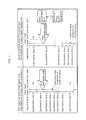
- FIG. 1 is a diagram showing a quantization width in the image coding method described in PTL 2.
- the quantization step (quantization width) is determined not on an area-by-area basis but on a pixel-by-pixel basis.
- the quantization step is determined according to a range (range of quantization step 1, range of quantization step 2, . . . ) of the predictive difference between the compression target pixel and the predictive value (see the circle mark in FIG. 1 ).
- a signal level (a position of a brightness value indicated by the circle mark on each of two vertical number lines in the left and right parts of FIG. 1 ) of a predictive value with respect to a dynamic range (a range of a brightness value of an image indicated by each of the two number lines in FIG. 1 ) of an input pixel signal
- a quantization step quantization step 1, 2, 4, . . . ) that can be used for quantization of the compression target pixel.
- the quantization step increases with predetermined intervals as the value of the target pixel is more away from the predictive value.
- the quantization step equally increases with predetermined intervals.
- a maximum quantization step (maximum quantization width) increases from quantization step “8” (S 1 in the left part) to “32” (S 2 in the right part).
- the number of patterns of the compression target pixel having the same quantization step “8” increases, too.
- the range of the possible predictive difference changes according to the signal level (the position of the circle mark) of the predictive value
- the number of patterns of the compression target pixel for which an arbitrary quantization width is adopted changes depending on the signal level of the predictive value, in the case where no adjacent pixel correlation is taken into consideration.
- a digital pixel signal received from an imaging device is temporarily stored in a memory such as an SDRAM (Synchronous Dynamic Random Access Memory).
- the temporarily stored data is then submitted to predetermined image processing, YC signal generation, zoom processing such as enlargement and reduction, and the like, and the processed data is temporarily stored in the SDRAM again.
- a request to read pixel data of an arbitrary area from the memory is often made as when clipping an arbitrary area of an image, when performing image processing for which reference or correlation between upper and lower pixels is needed, or the like.
- variable length coded data random accessibility cannot be attained because it is impossible to read an arbitrary area at some midpoint of coded data.
- the present invention has an object of realizing fixed length coding to maintain random accessibility, while preventing image quality degradation by fixing the number of pixel patterns having an arbitrary quantization width without depending on a signal level of a predictive value.
- the image coding method is executed by an image processing unit (image processing unit 2820 ) when writing an image to an SDRAM (SDRAM 2860 ).
- the image coding method is executed by the image processing unit (image processing unit 2820 ) on the image to be written.
- the image coding method is executed by an imaging unit (imaging unit 2810 A) when providing an image captured by the imaging unit to an image processing unit (image processing unit 2820 A).
- the image coding method is executed by the imaging unit on the image to be written.
- the image coded according to the image coding method is, for example, an image of raw data. That is, the image coding method is employed in such a case where an image needs to be coded at high speed by a simple structure.
- a difference between a target pixel to be coded and a predictive value of the target pixel is calculated.
- the coding target pixel can be obtained from the calculated difference and the predictive value.
- the difference calculated in the first step is quantized to generate a quantization value that represents the difference with a smaller amount of information (number of bits) than the amount of information (number of bits) of the difference.
- the target pixel is coded to the quantization value at high speed by a simple structure.
- the quantization value generated here has the same bit length regardless of, for example, the quantity represented by the quantization value. That is, the generated quantization value is a fixed length code.
- an image coding method is an image coding method (in a digital still camera, a surveillance camera, or the like) for compressing pixel data (raw data) of a compression target pixel, the image coding method including: generating a predictive value of the pixel data from at least one surrounding pixel located near the compression target pixel; code-converting (binary code to Gray code conversion) the pixel data to generate a code (Gray code) of the pixel data; quantizing bit change information (exclusive OR) to a quantization value that has a smaller number of bits than the bit change information, to compress the pixel data to the quantization value, the bit change information being information of a bit change between the code of the pixel data generated in the code-converting and a code (Gray code generated by code-converting the predictive value, i.e.
- the quantizing includes: determining, as a quantization width, the number of bits obtained by subtracting a bit length of the quantization value from the number of effective bits of the bit change information generated in the performing; and quantizing the bit change information generated in the performing, with the quantization width determined in the determining.
- coding is performed by a method that does not depend on a signal level of a predictive value without adding more memory by means of sequential processing, to solve the problems stated above.
- one aspect of the present invention is an image coding method for compressing each of a plurality of pieces of pixel data that constitute image data, the image coding method including: a predictive pixel generation step of generating a predictive value from at least one pixel located near a coding target pixel; and a code conversion step of code-converting the pixel data, wherein the pixel data is compressed by quantizing bit change information of a bit change between the code-converted coding target pixel and the predictive value to obtain coded data including a quantization value.
- the code conversion step may include converting the pixel data from a binary code to a Gray code.
- This image coding method achieves sufficiently high image quality, fixed-length quantized (compressed) quantization value generation, and ease of processing.
- bit change information is quantized unlike conventional difference coding, the number of pixel patterns having an arbitrary quantization width can always be fixed without depending on a signal level of a predictive value. Furthermore, code conversion and bit pattern generation for reducing the information amount of the bit change information enable quantization error reduction.
- FIG. 1 is a diagram regarding PTL 2
- FIG. 2 is a flowchart showing an image coding process in an image coding apparatus
- FIG. 3 is a block diagram showing structures of an image coding apparatus and an image decoding apparatus in an embodiment of the present invention
- FIG. 4 is a diagram explaining prediction expressions in a predictive pixel generation unit
- FIG. 5 is a diagram showing an image coding process example and each operation result
- FIG. 6 is a diagram showing an example of the number of effective bits of bit change information, a quantization width, and a quantization result
- FIG. 7A is a diagram showing a bit image before image coding
- FIG. 7B is a diagram showing a bit image after image coding
- FIG. 8 is a flowchart showing a decoding process in an image decoding apparatus
- FIG. 9 is a diagram showing a decoding process example and each operation result
- FIG. 10 is a block diagram showing a structure of a code generation unit
- FIG. 11 is a flowchart showing an image coding process in Variation 1;
- FIG. 12 is a diagram showing an image coding process example and each operation result in Variation 1;
- FIG. 13 is a diagram showing a bit image after image coding in Variation 1;
- FIG. 14 is a flowchart showing a quantization width determination process in Variation 1;
- FIG. 15 is a block diagram showing a structure of a quantization width determination unit in image coding in Variation 1;
- FIG. 16 is a diagram showing bit patterns generated by a bit pattern generation unit
- FIG. 17 is a diagram showing a quantization information ID in Variation 2;
- FIG. 18A is a diagram showing each operation result by bit pattern generation in Variation 2;
- FIG. 18B is a diagram showing each operation result by bit pattern generation in Variation 2;
- FIG. 19 is a flowchart showing a quantization width determination process in Variation 2;
- FIG. 20 is a block diagram showing a structure of a quantization width determination unit in image decoding in Variation 2;
- FIG. 21 is a diagram showing a decoding process example and each operation result in Variation 2;
- FIG. 22 is a flowchart showing a quantization width determination process in Variation 3.
- FIG. 23 is a block diagram showing a structure of a quantization width determination unit in image coding in Variation 3;
- FIG. 24 is a diagram showing a detection pattern for match detection by a pattern detection unit
- FIG. 25 is a diagram showing a quantization information ID in Variation 3.
- FIG. 26 is a block diagram showing a structure of a quantization width determination unit that includes a bit pattern generation unit and a pattern detection unit;
- FIG. 27 is a diagram showing a quantization information ID in the case where the bit pattern generation unit and the pattern detection unit are included;
- FIG. 28 is a block diagram showing a structure of a digital still camera in Variation 4.
- FIG. 29 is a block diagram showing a structure of a digital still camera in Variation 5.
- FIG. 30A is a diagram showing a quantization information ID in Variation 5.
- FIG. 30B is a diagram showing an output bit image in Variation 5.
- FIG. 31 is a block diagram showing a structure of a surveillance camera in Variation 6;
- FIG. 32 is a block diagram showing a structure of a surveillance camera in Variation 7;
- FIG. 33 is a flowchart in Variation 8.
- FIG. 34 is a flowchart showing Step S 13 shown in FIG. 33 in detail
- FIG. 35 is a flowchart showing Step S 203 shown in FIG. 34 in detail;
- FIG. 36 is a flowchart showing Step S 204 shown in FIG. 34 in detail;
- FIG. 37 is a flowchart showing Step S 206 shown in FIG. 34 in detail
- FIG. 38 is a flowchart showing Step S 207 shown in FIG. 34 in detail
- FIG. 39 is a block diagram showing a structure of an image coding apparatus in Variation 8.
- FIG. 40 is a diagram showing results in Variation 1;
- FIG. 41 is a diagram showing processing results of Step S 203 shown in FIG. 34 ;
- FIG. 42 is a diagram showing processing results of Step S 204 shown in FIG. 34 ;
- FIG. 43 is a flowchart showing processes in a system according to the present invention.
- An image coding method (method used in image coding apparatuses 100 , 100 b , 100 c , 100 cx , digital still camera 2800 , surveillance camera 3100 , and the like, FIG. 2 , Step S 4 B in FIG. 43 ) described below is an image coding method for compressing pixel data (raw data of an image captured (Step S 4 A) by a camera such as the digital still camera 2800 ( FIG. 28 ) or the surveillance camera 3100 ( FIG.
- the image coding method including: generating a predictive value of the pixel data from at least one surrounding pixel located near the compression target pixel (predictive pixel generation unit 102 , Steps S 102 , S 4 B 1 ); code-converting (e.g.
- the pixel data to generate a code (Gray code) of the pixel data (code conversion unit 103 (conversion processing unit 103 x ), Step S 103 , S 4 B 2 ); and quantizing bit change information (exclusive OR, change extraction unit 104 , Steps S 104 , S 4 B 3 ) to a quantization value (of a fixed length) that has a smaller number of bits than the bit change information, to compress the pixel data to the quantization value, the bit change information being information of a bit change between the code of the pixel data generated in the code-converting and a code (Gray code generated by code-converting the predictive value, i.e. the same type of code as the code of the pixel data) of the predictive value generated in the generating (quantization processing unit 106 , quantization unit 106 x , Steps S 106 , S 4 B 4 ).
- the following operation may be performed in a given situation.
- An image is captured by a camera (e.g. the digital still camera 2800 ( FIG. 28 ), the surveillance camera 3100 ( FIG. 31 )) (Step S 4 A).
- a camera e.g. the digital still camera 2800 ( FIG. 28 ), the surveillance camera 3100 ( FIG. 31 )
- a quantized quantization value obtained by compressing pixel data of raw data in the captured image is stored in an SDRAM 2860 ( FIG. 28 ) (Step S 4 C).
- an exclusive OR (bit change information) of a Gray code (Step S 4 B 2 ) of the pixel data of the raw data and a Gray code of a predictive value (Step S 4 B 1 ) of the pixel data (Step S 4 B 2 ) is calculated (Steps S 4 B 1 to S 4 B 3 ).
- the quantization value obtained by quantizing the calculated exclusive OR is generated to thereby compress the pixel data to the quantization value (Step S 4 B 4 ).
- Step S 4 B The generated (Step S 4 B) and stored (Step S 4 C) quantization value is read and decompressed (inverse quantization, image decoding method, Step S 4 D: S 4 D 1 to S 4 D 4 ) to the pre-compression pixel data.
- the exclusive OR of the Gray code is quantized, unlike the conventional process of difference quantization. This reduces a loss of information in quantization, with it being possible to prevent degradation and enhance image quality.
- an exclusive OR operation is performed when generating the exclusive OR from the code (Step S 4 B 3 in FIG. 43 ).
- an exclusive OR operation is performed when generating the code from the exclusive OR (Step S 4 D 3 ). Since the same operation is performed for both coding and decoding, ease of processing can further be enhanced.
- the quantizing may include rearranging the bit change information according to a predetermined method (see bit patterns 1 to 3 in FIG. 16 ), and quantizing the rearranged bit change information to the quantization value.
- the image coding method may include performing an exclusive OR operation on the code of the pixel data generated in the code-converting and the code of the predictive value generated in the generating, to generate the bit change information as a result of the operation (change extraction unit 104 , Step S 4 B 3 ), wherein the quantizing includes: determining, as a quantization width, the number of bits (1, 1, 0, 0, 2 in the third row in the lower table in FIG. 5 ) obtained by subtracting a bit length (8 bits in the fourth row) of the quantization value from the number of effective bits (the second row) of the bit change information generated in the performing (quantization width determination unit 105 ); and quantizing the bit change information generated in the performing, with the quantization width determined in the determining.
- the change extraction step (the above-mentioned performing) may be included in the code conversion step (the above-mentioned code-converting) (Steps S 4 B 2 and S 4 B 3 ).
- the change extraction step may thus be part of the image coding method.
- the result of the change extraction step performed separately from the image coding method may be used in the image coding method.
- Other forms are also applicable.
- the determining may include: rearranging bit data in the bit change information of N bits generated in the performing, to obtain a plurality of bit patterns (e.g. bit patterns 2 to 3 or 1 to 3 in FIG. 16 ) resulting from different rearrangements (see bit patterns 1 to 3 in FIG. 18 A), N being a natural number; adopting a bit pattern (e.g. bit pattern 2 ) having a minimum number of effective bits from among the plurality of bit patterns; and determining, as the quantization width used for the quantization, the number of bits obtained by subtracting the bit length (e.g. 8) of the quantization value from the number of effective bits (e.g. 10) of the adopted bit pattern.
- a plurality of bit patterns e.g. bit patterns 2 to 3 or 1 to 3 in FIG. 16
- N being a natural number
- determining, as the quantization width used for the quantization the
- At least one (e.g. bit pattern 2 in FIG. 16 ) of the plurality of bit patterns may be second bit change information obtained by dividing first bit change information (bit pattern 1 in FIG. 16 ) into high-order bits and low-order bits at a predetermined bit position (arrow position in bit pattern 2 in FIG. 16 ) and rearranging the high-order bits in reverse order, the first bit change information being the bit change information of N bits generated in the performing.
- At least one (bit pattern 3 in FIG. 16 ) of the plurality of bit patterns may be third bit change information (bit data such as b 11 , b 10 , . . . , b 7 , b 6 changed in position) obtained by changing bit positions of a plurality of pieces of bit data (higher bits with respect to arrow position) in first bit change information (bit pattern 1 ) which is the bit change information of N bits generated in the performing.
- third bit change information bit data such as b 11 , b 10 , . . . , b 7 , b 6 changed in position
- At least one of the plurality of bit patterns may be fourth bit change information of L bits obtained by extracting only information of a change in K consecutive bits in first bit change information (bit pattern 1 in FIG. 24 ) which is the bit change information of N bits generated in the performing, the K consecutive bits being consecutive from a predetermined bit position (between b 5 and b 6 ), K (6 bits from b 6 to b 11 ) being a natural number smaller than N, and L (e.g. 5 bits from b 7 to b 11 ) being smaller than K.
- the determining may include determining, for each group (e.g. group of three pieces of pixel data in the second to fourth columns in the lower table in FIG. 12 ) composed of a plurality of pieces of pixel data, a common quantization width (e.g. maximum quantization width “1” in the fourth row in the lower table) used for quantization of all of the plurality of pieces of pixel data.
- group e.g. group of three pieces of pixel data in the second to fourth columns in the lower table in FIG. 12
- a common quantization width e.g. maximum quantization width “1” in the fourth row in the lower table
- the determining may include coding the determined quantization width to a code (e.g. code in the third column in FIG. 6 ) of Q bits, to generate coded data (e.g. 8-bit data of “quantization value” in FIG. 7B ) for specifying the quantization width used for inverse quantizing the quantization value, Q being a natural number.
- code e.g. code in the third column in FIG. 6
- coded data e.g. 8-bit data of “quantization value” in FIG. 7B
- the image coding method may further include: determining a need of whether or not to substitute a value of the pixel data of the compression target pixel (substitution determination unit 11 in FIG. 39 , Step S 205 in FIG. 34 ); and substituting the value of the pixel data of the compression target pixel (e.g. 512 of the pixel P 32 in FIG. 42 ) with an arbitrary (appropriate) value (511 in “512 ⁇ 511” of the pixel P 32 ) (Steps S 206 ( 602 ), S 207 , pixel value substitution unit 12 ), wherein, in the case of determining in the determining a need that the value of the pixel data needs to be substituted (Step S 601 in FIG.
- the code-converting includes code-converting the pixel data (511) whose value (512 in “512 ⁇ 511” of the pixel P 32 in FIG. 42 ) is substituted in the substituting to generate the code (Gray code) of the pixel data (511), and the quantizing includes quantizing the bit change information (exclusive OR) between the code of the pixel data generated in the code-converting and the code of the predictive value (500 of the pixel P 31 ) (Step S 1102 in FIG. 33 ).
- quantization is performed with a small quantization width (see a quantization width “0” in the third row in the middle table in FIG. 42 ) calculated from two pixel values (500 of the pixel P 31 and 511 of the pixel P 32 after substitution) with no power of 2 (512) being included from one pixel value to the other. This reduces a quantization error and prevents degradation, contributing to high image quality.
- the determining a need may include determining whether or not the value of the pixel data of the compression target pixel needs to be substituted, according to the quantization width determined in the determining.
- the determining a need may include determining that the value of the pixel data of the compression target pixel needs to be substituted, in the case where the quantization width determined in the determining is W which is an arbitrary nonzero natural number.
- a second quantization width smaller than the above-mentioned first quantization width may be determined and put to use for quantization.
- a predetermined value e.g. 511 in “512 ⁇ 511” of the pixel P 32 in FIG. 42
- the substituting may include substituting the value of the pixel data of the compression target pixel with the power of 2 (e.g. 512) in the case of substituting the value in a positive direction (substituting with a larger value as in FIG. 41 , Step S 205 : N), and substituting the value of the pixel data of the compression target pixel with a result of subtracting 1 from the power of 2 (e.g. 511) in the case of substituting the value in a negative direction (substituting with a smaller value as in FIG. 42 , Step S 205 : Y).
- 2 e.g. 512
- the determining may include generating a quantization information ID (the fourth column in FIG. 17 ) that includes (specifies) at least quantization width information (the second column) and bit pattern information (the third column), the quantization width information being information for specifying the quantization width used for the quantization, and the bit pattern information being information for specifying the bit pattern adopted in the determining.
- a quantization information ID the fourth column in FIG. 17
- the quantization width information being information for specifying the quantization width used for the quantization
- the bit pattern information being information for specifying the bit pattern adopted in the determining.
- the generating coded data may include generating, as the coded data, packed data (64-bit data in FIG. 7B ) that includes unquantized pixel data (12-bit data of the pixel P 1 ) of a leading pixel (pixel P 1 in FIGS. 7A and 7B ) and one or more quantization values (five quantization values of the pixels P 2 to P 6 ) obtained by quantizing, in the quantizing, pixel data of each pixel (pixels P 2 to P 6 ) following the leading pixel within a predetermined interval (fixe pixels of the pixels P 2 to P 6 ) (packing unit 107 , Step S 107 ).
- the pixel data may be raw data which an image coding apparatus (image coding apparatus 100 in FIG. 28 ) that executes the image coding method receives from an imaging device (imaging device 2812 ).
- a dynamic range M of coded data of the pixel may be changed for each color component.
- the determining may include determining the quantization width separately for each color component.
- the pixel data may be data of a luminance signal or a chrominance signal generated by an image processing apparatus from raw data received from an imaging device.
- the pixel data may be data of a luminance signal or a chrominance signal generated by a decompression apparatus (e.g. digital still camera 2800 ) decompressing a JPEG (Joint Photographic Experts Group) image.
- JPEG Joint Photographic Experts Group
- An image decoding method may be an image decoding method (Step S 4 D in FIG. 43 ) for decoding a quantization value to pixel data, the quantization value being a result of quantizing bit change information of a bit change between a code of the pixel data and a code of a predictive value of the pixel data, the predictive value being generated from at least one pixel located near a pixel of the pixel data, the image decoding method including: generating the predictive value of the pixel data from already decoded preceding pixel data (predictive pixel generation unit 112 , Step S 4 D 1 ); inverse quantizing the quantization value to generate the bit change information (inverse quantization processing unit 114 , inverse quantization unit 113 x , Step S 4 D 2 ); and inverse code-converting (inverse code conversion unit 116 , Step S 4 D 4 ) the code (code generation unit 115 , Step S 4 D 3 ) of the pixel data to obtain the pixel data, the code of the pixel data being specified from the code
- the image decoding method may include performing an exclusive OR operation on the bit change information generated in the inverse quantizing and the code of the predictive value generated in the generating, to generate the code of the pixel data as a result of the operation (code generation unit 115 , Step S 4 D 3 ).
- the code generation step (the above-mentioned performing) (Step S 4 D 3 ) may be included in the inverse code conversion step (the above-mentioned inverse code-converting) (Steps S 4 D 3 and S 4 D 4 ).
- the code generation step (Step S 4 D 3 ) may not be included in the above-mentioned inverse code conversion step (only Step S 4 D 4 ).
- Step S 4 D 3 performed separately from the inverse code conversion step (only Step S 4 D 4 ) may be used in the inverse code conversion step (only Step S 4 D 4 ).
- Step S 4 D 3 performed separately from the image decoding method may be used in the image decoding method.
- the determining may include specifying the quantization width and bit pattern information indicated by a quantization information ID, the bit pattern information being information for specifying an adopted bit pattern from among a plurality of bit patterns.
- the quantization width and the bit pattern information may be indicated by the quantization information ID.
- the present invention may be realized as an integrated circuit, a method, a digital still camera, a digital video camera, a surveillance camera, a solid-state imaging device (including the image coding apparatus or the like), a computer program, and so on.
- FIG. 2 is a flowchart showing an image coding method in the embodiment of the present invention.
- FIG. 3 is a block diagram showing structures of an image coding apparatus 100 and an image decoding apparatus 110 in the embodiment of the present invention.
- part or whole of a coding process of the image coding apparatus 100 in this embodiment is implemented by hardware such as LSI (Large Scale Integration) or a program executed by a CPU (Central Processing Unit) or the like. The same applies to each variation of this embodiment.
- LSI Large Scale Integration
- CPU Central Processing Unit
- the following describes a process of coding an image (hereafter referred to as an image coding process) by the image coding apparatus 100 , with reference to FIGS. 2 and 3 .
- a processing target pixel value input unit 101 receives a pixel (target pixel) to be coded.
- each piece of pixel data is digital data of N bits
- quantized pixel data (hereafter referred to as a quantization value) corresponding to each piece of pixel data is digital data of M bits.
- At least one leading target pixel, a plurality of quantization values corresponding to a plurality of pieces of pixel data, and a code (hereafter referred to as quantization width information) indicating a quantization width of each quantization value are packed into S bits by a packing unit 107 .
- the packed data is then outputted from the image coding apparatus 100 .
- N, M, and S are predetermined natural numbers.
- the processing target pixel value input unit 101 provides the received pixel data to a predictive pixel generation unit 102 and a code conversion unit 103 at appropriate timings.
- Step S 101 in FIG. 2 YES
- a quantization process Steps S 102 to S 106
- the processing target pixel value input unit 101 directly provides the received pixel data to the packing unit 107 .
- Step S 101 in FIG. 2 NO
- the process goes to predictive pixel generation.
- the pixel data provided to the predictive pixel generation unit 102 is any of the following first to third data.
- the first data is a leading target pixel received by the processing target pixel value input unit 101 earlier than the coding target pixel of interest.
- the second data is a preceding coding target pixel received by the processing target pixel value input unit 101 earlier than the coding target pixel of interest.
- the third data is pixel data obtained by decoding, by the image decoding apparatus 110 , coded data generated by the image coding apparatus 100 and sent to the image decoding apparatus 110 earlier.
- the predictive pixel generation unit 102 generates a predictive value of the current target pixel of interest, using the received pixel data (e.g. the above-mentioned first data) (Step S 102 in FIG. 2 ).
- Prediction coding is a method of generating a predictive value for a coding target pixel and coding a difference between the coding target pixel and the predictive value.
- pixel data there is a high possibility that a pixel near a pixel of interest has a value equal or close to the pixel of interest. Based on this, the value of the coding target pixel of interest is predicted from surrounding pixel data, as the predictive value. The difference is minimized in this manner, thereby reducing the quantization width.
- FIG. 4 is a diagram explaining positions of surrounding pixels used for predictive value calculation.
- “x” is a pixel value of a pixel of interest (target pixel)
- “a”, “b”, and “c” are pixel values of three surrounding pixels for calculating a predictive value “y” of the pixel of interest.
- the predictive pixel generation unit 102 calculates the predictive value “y” of the pixel of interest using any of the pixel values “a”, “b”, and “c” of the surrounding pixels of the pixel of interest.
- the predictive pixel generation unit 102 calculates the predictive value using a prediction expression (e.g. the prediction expression (1)) out of the above-mentioned prediction expressions (1) to (7) used for prediction coding, and provides the calculated predictive value to the code conversion unit 103 .
- the prediction expression (1) is used in Step S 102 , as an example.
- the code conversion unit 103 code-converts each of the coding target pixel received from the processing target pixel value input unit 101 and the predictive value received from the predictive pixel generation unit 102 , to a code (Gray code) expressed in N bits.
- the code conversion unit 103 provides the code (hereafter referred to as the code of the target pixel) corresponding to the coding target pixel and the code (hereafter referred to as the code of the predictive value) corresponding to the predictive value obtained as a result of code conversion, to the change extraction unit 104 (Step S 103 in FIG. 2 ).
- the change extraction unit 104 performs an exclusive OR operation on the code of the coding target pixel and the code of the predictive value each expressed in N bits, to obtain bit change information E of N bits.
- the bit change information is a code that is used together with the code of the predictive value to calculate the code of the target pixel.
- the change extraction unit 104 provides the obtained bit change information E to a quantization width determination unit 105 and a quantization processing unit 106 (Step S 104 in FIG. 2 ).
- the quantization width determination unit 105 determines a quantization width J based on the bit change information E received from the change extraction unit 104 , and provides the determined quantization width J to the quantization processing unit 106 and the packing unit 107 (Step S 105 in FIG. 2 ).
- the quantization width J is a value obtained by subtracting a bit length M of a quantization value from the number of effective bits of the bit change information E.
- J is a positive integer, and is set to 0 in the case where the number of effective bits of the bit change information E is smaller than the bit length M of the quantization value generated by quantization.
- the quantization processing unit 106 performs a quantization process of quantizing the bit change information E received from the change extraction unit 104 , with the quantization width J calculated by the quantization width determination unit 105 .
- the quantization process with the quantization width J is a bit shift operation that shifts the bit change information E between the coding target pixel and the predictive value of the coding target pixel lower by the quantization width J.
- the quantization processing unit 106 provides the quantization result (quantization value) to the packing unit 107 (Step S 106 in FIG. 2 ).
- the quantization processing unit 106 does not perform quantization in the case where the quantization width J is 0.
- the packing unit 107 combines at least one leading target pixel, a plurality of quantization values, and at least one piece of quantization width information of Q bits (Q is a natural number), thereby packing these data into S-bit data (packed data) (see, for example, FIGS. 7A and 7B described later).
- the packing unit 107 outputs the packed data to a memory such as an SDRAM or an unpacking unit 111 (Step S 107 in FIG. 2 ).
- the fixed bit length S which is the bit length of the packed data may be the same number of bits as a data transfer bus width in an integrated circuit used.
- dummy data e.g. rightmost 4 bits in FIG. 7A described later
- FIG. 5 is a diagram explaining the image coding process in this embodiment.
- the processing target pixel value input unit 101 sequentially receives pixel data of a fixed bit length (N bits).
- M the quantization value bit length M is 8 bits.
- the packing unit 107 packs the received data into S bits, and outputs the packed data from the image coding apparatus 100 .
- the fixed bit length S is supposed to be 64 bits.
- the code conversion performed by the code conversion unit 103 is Gray code conversion.
- the reason for converting the pixel data to a Gray code is that a bit change when representing an approximate value can be reduced to attain a higher compression rate.
- a method of converting a decimal value to a Gray code a method of exclusive ORing each bit and its adjacent higher bit sequentially from a least significant bit in a bit string that represents the decimal value in binary code is typically employed. Any code conversion other than Gray code conversion is also applicable so long as a bit change between original data and data representing an approximate value of the original data is smaller than a bit change expressed in binary code.
- FIG. 5 six pieces of pixel data received by the processing target pixel value input unit 101 are shown as an example.
- the processing target pixel value input unit 101 receives 12-bit pixel data corresponding to each of pixels P 1 , P 2 , . . . , P 6 in this order.
- a numeric value (e.g. 300) shown in each of the fields of the pixels P 1 to P 6 is a signal level indicated by the corresponding pixel data.
- the pixel data corresponding to the pixel P 1 is a leading target pixel.
- This embodiment describes an example where the predictive pixel generation unit 102 calculates the predictive value of the coding target pixel according to the prediction expression (1) out of the above-mentioned prediction expressions (1) to (7).
- the calculated predictive value of the coding target pixel is a value (“a” in FIG. 4 ) of a left adjacent pixel of the coding target pixel. That is, the predictive pixel generation unit 102 predicts that the pixel value of the coding target pixel has a high possibility of being the same pixel value (level) as the pixel received immediately before the coding target pixel.
- Step S 101 is performed first.
- the processing target pixel value input unit 101 determines whether or not the received pixel data is a leading target pixel. In the case where the determination of Step S 101 results in YES, the processing target pixel value input unit 101 stores the received pixel data in an internal buffer, and also provides the received pixel data to the packing unit 107 . The process then goes to below-mentioned Step S 107 . In the case where the determination of Step S 101 results in NO, on the other hand, the process goes to Step S 102 .
- the processing target pixel value input unit 101 When the processing target pixel value input unit 101 receives the pixel data of the pixel P 1 which is a leading target pixel, the processing target pixel value input unit 101 stores the received pixel data in the internal buffer, and also provides the received pixel data to the packing unit 107 .
- the processing target pixel value input unit 101 writes the received pixel data over the already stored pixel data in the internal buffer.
- the processing target pixel value input unit 101 receives the pixel data (coding target pixel data) of the pixel P 2 , where the received coding target pixel data indicates a pixel value “220” (see FIG. 5 ). Since the received pixel data is not a leading target pixel (Step S 101 : NO), the processing target pixel value input unit 101 provides the received pixel data to the code conversion unit 103 .
- the processing target pixel value input unit 101 also provides the pixel data stored in the internal buffer to the predictive pixel generation unit 102 .
- the pixel data provided here indicates the pixel value “300” of the pixel P 1 .
- the processing target pixel value input unit 101 stores the received coding target pixel data in the internal buffer by overwriting, and provides the received coding target pixel data to the code conversion unit 103 . The process then goes to Step S 102 .
- Step S 102 the predictive pixel generation unit 102 calculates the predictive value of the coding target pixel.
- the predictive pixel generation unit 102 calculates the predictive value using, for example, the prediction expression (1) as mentioned earlier. This being so, the pixel value (“300”) (the pixel value of P 1 ) indicated by the pixel data received from the processing target pixel value input unit 101 is calculated by the predictive pixel generation unit 102 as the predictive value.
- the predictive pixel generation unit 102 provides the calculated predictive value “300” to the code conversion unit 103 .
- the predictive pixel generation unit 102 specifies, as the predictive value, the value indicated by the (h ⁇ 1)-th pixel data received from the processing target pixel value input unit 101 as described above.
- the predictive pixel generation unit 102 may specify a value provided to the image coding apparatus 100 from the image decoding apparatus 110 , as the predictive value.
- This value is a value corresponding to the (h ⁇ 1)-th pixel data coded by the image coding apparatus 100 . That is, the predictive pixel generation unit 102 may obtain (receive), from the image decoding apparatus 110 , a pixel value (value) indicated by pixel data generated by the image decoding apparatus 110 decoding input data, and specify the obtained pixel value as the predictive value of the h-th coding target pixel.
- Step S 103 the code conversion unit 103 performs Gray code conversion on each of the coding target pixel and the predictive value.
- the code conversion unit 103 receives the coding target pixel data of the value “220” (the value of P 2 in FIG. 5 ) and the predictive value “300” (the value of P 1 ). Accordingly, the code of the target pixel and the code of the predictive value as a result of code conversion are respectively “000010110010” and “000110111010” which are each a Gray code of N (12) bits (the second row and third and second columns in the upper table in FIG. 5 ).
- Step S 104 the change extraction unit 104 performs an exclusive OR operation.
- the change extraction unit 104 takes an exclusive OR of the code of the target pixel and the code of the predictive value received from the code conversion unit 103 , to calculate the bit change information E.
- the change extraction unit 104 receives the code of the target pixel “000010110010” and the code of the predictive value “000110111010” (the second row and third and second columns in the upper table in FIG. 5 ).
- the change extraction unit 104 exclusive ORs the code of the target pixel (“000010110010”) and the code of the predictive value (“000110111010”), to calculate the bit change information E “000100001000” (“100001000”) (the first row and second column in the lower table in FIG. 5 ).
- the change extraction unit 104 provides the calculated bit change information E to the quantization width determination unit 105 and the quantization processing unit 106 .
- Step S 105 the quantization width determination unit 105 performs a quantization width determination process.
- the quantization width determination unit 105 specifies the number of effective bits (the bit length underlined in the first row and second column in the lower table in FIG. 5 ) of the bit change information E (the first row and second column in the lower table in FIG. 5 ), i.e. a bit length necessary for expressing bit change information.
- the bit change information E is “000100001000” (the first row and second column in the lower table in FIG. 5 ).
- the number of effective bits is 9 bits.
- the number of effective bits is a result of subtracting, from a total number of bits (12 in the above example) of the code, the number of consecutive “0”s (3 in the above example) from the most significant bit in the code, where the number of consecutive “0”s is equal to or more than 0.
- the quantization width determination unit 105 sets the quantization width J, using the predetermined quantization value bit length M and the number of effective bits of the bit change information E.
- the quantization width determination unit 105 provides the calculated quantization width J to the quantization processing unit 106 .
- the quantization width determination unit 105 also generates quantization width information (see FIG. 6 described later) of Q bits by coding the quantization width J, and provides the generated quantization width information to the packing unit 107 .
- the bit length Q of the quantization width information is assumed here to be 2.
- FIG. 6 is a diagram showing a table of correspondence between the number of effective bits of the bit change information E, the quantization width J, and the Q-bit quantization width information.
- the quantization width information provided to the packing unit 107 is “01” as shown in FIG. 6 .
- J is a non-negative number
- J is set to 0 when the number of effective bits of the bit change information E is smaller than M (8).
- Step S 106 the quantization processing unit 106 performs a quantization process.
- the quantization processing unit 106 receives the quantization width J calculated by the quantization width determination unit 105 , and performs a bit shift operation that shifts the bit change information E received from the change extraction unit 104 lower by the number of bits indicated by the received quantization width J, thereby quantizing the received bit change information E.
- the quantization width J received from the quantization width determination unit 105 is 1, and the bit change information E received from the change extraction unit 104 is “000100001000” (the first row and second column in the lower table in FIG. 5 ).
- the quantization processing unit 106 bit-shifts “000100001000” lower by the quantization width J (1), to yield “00010000100” (quantization value). Since the quantization value bit length M is 8 bits, the quantization processing unit 106 provides low-order 8-bit data in the calculated quantization value “00010000100”, i.e. quantized bit change information “10000100”, to the packing unit 107 .
- Step S 107 the packing unit 107 performs a packing process of packing into predetermined S bits.
- the packing unit 107 stores the leading target pixel P 1 received from the processing target pixel value input unit 101 , in an S-bit buffer memory.
- the packing unit 107 sequentially stores the Q-bit quantization width information as a result of coding the quantization width J received from the quantization width determination unit 105 and the quantization value of the coding target pixel P 2 received from the quantization processing unit 106 , in the buffer memory.
- the fixed bit length S (packed data bit length) is 64
- Step S 108 After the packing process for the coding target pixel ends, the process goes to Step S 108 .
- Step S 101 the process goes to Step S 101 , and the image coding apparatus 100 executes at least one of Steps S 101 to S 107 on the next pixel data received by the processing target pixel value input unit 101 .
- the image coding apparatus 100 thus repeats Steps S 101 to S 107 for the pixels P 3 to P 6 shown in FIG. 5 , and sequentially stores resulting data in the buffer memory.
- Step S 108 In the case where the determination of Step S 108 results in YES, the image coding apparatus 100 outputs the coded data in the buffer memory on an S-bit basis, and then the process goes to Step S 109 .
- Step S 109 the image coding apparatus 100 determines whether or not the coding process for one picture is completed as a result of outputting the coded pixel data in preceding Step S 108 . In the case where the determination of Step S 109 results in YES, the coding process ends. In the case where the determination of Step S 109 results in NO, the process goes to Step S 101 to execute at least one of Steps S 101 to S 108 .
- FIG. 5 shows the data as a result of code-converting the coding target pixels P 2 to P 6 by the code conversion unit 103 (the second row in the upper table in FIG. 5 ), the exclusive OR (the first row in the lower table), the number of effective bits (the second row in the lower table), the quantization width (the third row in the lower table), and the 8-bit quantization value packed by the packing unit 107 (the fourth row in the lower table).
- FIG. 7A is a diagram showing a bit image of S bits in the case where the image coding process is not applied.
- FIG. 7B is a diagram showing a bit image of S bits stored in the buffer memory by the packing unit 107 and outputted from the image coding apparatus 100 , in the case where the image coding process is applied.
- the packing unit 107 first receives the pixel P 1 of N (12) bits as the leading target pixel, as shown by leftmost 12 bits. For each of the succeeding pixel data P 2 to P 6 , the quantization width information and the quantization value are paired as coded data of Q (2) bits and M (8) bits respectively. Thus, the coded data of the pixel P 2 and the like is included in the packed data, following the first 12-bit data. By coding the pixels P 2 to P 6 in the above manner, a larger number of pixels can be included in the packed data of the same bit length.
- the number of pixels transmittable in one transfer can be increased, with it being possible to ensure that the bus width is fixed in length. Accordingly, in the case where data access to compressed pixel data is requested, the data access can be made merely by accessing data packed per bus width. If the bus width and the packed data bit length do not match as there is one or more unused bits, the unused bits may be replaced with dummy data as shown in FIGS. 7A and 7B .
- the code conversion by the code conversion unit 103 performed upon quantization for reducing the information amount of the bit change information enables quantization error reduction.
- the bit change information is quantized to a fixed length code, so that image quality degradation can be reduced while maintaining random accessibility.
- FIG. 8 is a flowchart showing an image decoding method.
- the following describes a process of decoding coded data (hereafter referred to as an image decoding process) by the image decoding apparatus 110 , with reference to FIGS. 3 and 8 .
- FIG. 8 is a flowchart showing the image decoding process performed by the image decoding apparatus 110 shown in FIG. 3 .
- the unpacking unit 111 receives coded data necessary for reconstructing the pixels P 1 to P 6 shown in FIG. 5 .
- the unpacking unit 111 analyzes fixed length coded data of S bits received from the packing unit 107 or the memory such as the SDRAM, and separates the fixed length coded data into a plurality of pieces of data. That is, the unpacking unit 111 separates the received fixed length coded data into a leading target pixel of N bits, quantization width information of Q bits, and a pixel to be decoded (hereafter referred to as a decoding target pixel, i.e. a quantization value) of M bits (Step S 801 in FIG. 8 ).
- the unpacking unit 111 provides the analyzed coded data to a quantization width determination unit 113 , an inverse quantization processing unit 114 , and an output unit 117 at appropriate timings.
- the unpacking unit 111 receives the coded data as pixel data of N bits having a pre-coding dynamic range. In such a case, an inverse quantization process is omitted, and the unpacking unit 111 provides the coded data of interest directly to the output unit 117 .
- the unpacking unit 111 provides the coded data to the quantization width determination unit 113 , where the process goes to a quantization width determination process in inverse quantization (Step S 804 in FIG. 8 ).
- the quantization width determination unit 113 determines a quantization width J′ for inverse quantization corresponding to each decoded target pixel, from the coded data (quantization width information) received from the unpacking unit 111 .
- the quantization width determination unit 113 provides the determined quantization width J′ to the inverse quantization processing unit 114 .
- the unpacking unit 111 provides the coded data to the inverse quantization processing unit 114 , where the process goes to an inverse quantization process.
- the inverse quantization processing unit 114 performs inverse quantization with the quantization width J′ for inverse quantization received from the quantization width determination unit 113 .
- the inverse quantization process with the quantization width J′ is a bit shift operation that shifts the coded data (quantization value) received from the unpacking unit 111 higher by the quantization width J′.
- the inverse quantization processing unit 114 calculates bit change information E′ expressed in N bits, as a result of the inverse quantization process.
- the inverse quantization processing unit 114 does not perform inverse quantization in the case where the quantization width J′ is 0 (Step S 805 in FIG. 8 ).
- Data received by a predictive pixel generation unit 112 is data inputted earlier than the decoding target pixel of interest and provided from the output unit 117 .
- This data is either a leading target pixel or pixel data (hereafter referred to as decoded pixel data) decoded and provided from the output unit 117 earlier.
- the predictive pixel generation unit 112 generates a predictive value expressed in N bits, using the received pixel data.
- a predictive value generation method employed here is a method using any of the above-mentioned prediction expressions (1) to (7).
- the predictive pixel generation unit 112 calculates the predictive value using the same prediction expression as the predictive pixel generation unit 102 in the image coding apparatus 100 .
- the predictive pixel generation unit 112 provides the calculated predictive value to a code generation unit 115 (Step S 806 in FIG. 8 ).
- the code generation unit 115 performs the same code conversion (Gray code conversion) as the code conversion unit 103 in the image coding apparatus 100 , on the predictive value received from the predictive pixel generation unit 112 .
- the code generation unit 115 thus generates a code of the predictive value.
- the received predictive value is a value before code conversion such as Gray code conversion.
- the code generation unit 115 performs the same code conversion as the code conversion unit 103 on such a received predictive value, to yield a code. In this way, the code generation unit 115 calculates the code (Gray code) corresponding to the received predictive value.
- the code generation unit 115 then performs an exclusive OR operation on the bit change information E′ of N bits received from the inverse quantization processing unit 114 and the code of the predictive value obtained by code conversion, to generate a code of the target pixel of N bits.
- the code generation unit 115 provides the generated code of the target pixel to an inverse code conversion unit 116 (Step S 807 in FIG. 8 ).
- the inverse code conversion unit 116 performs inverse conversion of the code conversion performed by the code conversion unit 103 in the image coding apparatus 100 , on the code of the target pixel received from the code generation unit 115 , thereby reconstructing pixel data.
- the inverse code conversion unit 116 provides the pixel data obtained by the inverse code conversion, to the output unit 117 (Step S 808 in FIG. 8 ).
- FIG. 9 is a diagram explaining the image decoding process in this embodiment.
- the image decoding apparatus 110 receives the data resulting from the image coding process of the six pieces of pixel data (pixels P 1 to P 6 ) in FIG. 5 , as an example.
- the plurality of pieces of coded data stored in the external memory are sequentially provided to the unpacking unit 111 as shown in FIG. 7B .
- the pixel data of the pixel P 1 is a leading target pixel, and so is expressed in 12 bits. Meanwhile, the data (quantization value) of each of the pixels P 2 to P 6 is decoding target pixel data, and so is expressed in 8 bits.
- Step S 801 is performed first.
- the unpacking unit 111 separates the coded data into predetermined bits as shown in FIG. 7B .
- the process then goes to Step S 802 .
- Step S 802 the unpacking unit 111 or the like determines whether or not the separated coded data is data of a leading target pixel. In the case where the determination of Step S 802 results in YES, the unpacking unit 111 provides the received pixel data to the output unit 117 . The process then goes to below-mentioned Step S 810 . In the case where the determination of Step S 802 results in NO, on the other hand, the process goes to Step S 803 .
- the unpacking unit 111 receives the pixel data of the pixel P 1 as a leading target pixel (Step S 802 : YES), and the leading target pixel indicates a pixel value “300” (the second row and second column in the upper table in FIG. 9 ). In this case, the unpacking unit 111 provides the received pixel data “300” to the output unit 117 .
- the output unit 117 provides the received leading target pixel to the predictive pixel generation unit 112 .
- Step S 803 the unpacking unit 111 determines whether or not the separated coded data is quantization width information. In the case where the determination of Step S 803 results in NO, the process goes to below-mentioned Step S 805 . In the case where the determination of Step S 803 results in YES, on the other hand, the unpacking unit 111 provides the received quantization width information to the quantization width determination unit 113 . The process then goes to Step S 804 .
- the coded data separated by the unpacking unit 111 is the quantization width information of the pixel P 2 , and the quantization width information indicates “01” (the second row and third column in the upper table in FIG. 9 ).
- the unpacking unit 111 provides the quantization width information “01” to the quantization width determination unit 113 .
- Step S 804 the quantization width determination unit 113 calculates the quantization width J′ for inverse quantization, from the received quantization width information.
- the quantization width J′ needs to be in agreement with the quantization width J used in the image coding process, and so is calculated based on the correspondence relationship in the table shown in FIG. 6 .
- the quantization width J′ is 1 (the third row and third column) as shown in FIG. 6 .
- the pixel P 2 is a decoding target pixel and the coded data separated by the unpacking unit 111 is the decoding target pixel data of the pixel P 2 . Since the separated coded data is not quantization width information (Step S 803 : NO), the process goes to Step S 805 .
- the decoding target pixel data indicates a pixel value “10000100” (a quantization value in the second row and fourth column in the upper table in FIG. 9 ).
- the unpacking unit 111 provides the separated decoding target pixel data “10000100” to the inverse quantization processing unit 114 .
- Step S 805 the inverse quantization processing unit 114 performs an inverse quantization process.
- the inverse quantization processing unit 114 performs a bit shift operation that shifts the decoding target pixel data (quantization value) received from the unpacking unit 111 higher by the number of bits indicated by the quantization width J′ for inverse quantization received from the quantization width determination unit 113 , thereby inverse quantizing the received quantization value.
- Data yielded as a result of inverse quantization is the bit change information E′ expressed in N (12) bits.
- the quantization width J′ received from the quantization width determination unit 113 is 1 (the third row and third column in the upper table in FIG. 9 ), and the decoding target pixel data (quantization value) received from the unpacking unit 111 is “10000100” (the second row and fourth column).
- the inverse quantization processing unit 114 performs inverse quantization by bit-shifting “10000100” higher by 1 bit, to yield “000100001000” (the fourth row and third column).
- the inverse quantization processing unit 114 provides the calculated code to the code generation unit 115 .
- the inverse quantization processing unit 114 provides the decoding target pixel data directly to the code generation unit 115 without performing inverse quantization.
- Step S 806 the predictive pixel generation unit 112 calculates the predictive value of the decoding target pixel.
- the predictive pixel generation unit 112 calculates the predictive value using the prediction expression (1) so as to adopt the same prediction method as in Step S 102 for predictive pixel generation in the image coding process in the image coding apparatus 100 .
- the predictive pixel generation unit 112 calculates the predictive value of the pixel P 2 .
- the predictive pixel generation unit 112 specifies the pixel data of the pixel P 1 which is decoding target pixel data received immediately before the pixel P 2 , as the current predictive value. That is, the predictive pixel generation unit 112 receives the pixel value “300” (the second row and second column in the upper table in FIG. 9 ) of the pixel P 1 from the output unit 117 , and sets the received pixel value “300” as the current predictive value.
- FIG. 10 is a diagram showing a structure of the code generation unit 115 .
- Step S 807 the code generation unit 115 calculates the code of the target pixel from the code of the predictive pixel, which is obtained by the code generation unit 115 code-converting the predictive value received from the predictive pixel generation unit 112 , and the bit change information E′ received from the inverse quantization processing unit 114 .
- the code generation unit 115 performs the same code conversion as the code conversion unit 103 in the image coding apparatus 100 on the predictive value received from the predictive pixel generation unit 112 , to generate the code (the code of the predictive value).
- the predictive value received from the predictive pixel generation unit 112 is “300” (the second row and second column in the upper table in FIG. 9 ), and the code conversion is Gray code conversion.
- the code generation unit 115 performs Gray code conversion on “300”, to yield “000110111010” (the fourth row and second column in the upper table in FIG. 9 ) which is the code of the predictive value of N (12) bits.
- the code generation unit 115 then performs an exclusive OR operation on the bit change information E′ of 12 bits received from the inverse quantization processing unit 114 and the code of the predictive value.
- the code generation unit 115 generates the code of the target pixel of 12 bits as a result of the exclusive OR operation, and provides the generated code to the inverse code conversion unit 116 .
- the bit change information E′ received from the inverse quantization processing unit 114 is “000100001000” (the fourth row and third column in the upper table in FIG. 9 ), and the code of the predictive value is “000110111010” (the fourth row and second column).
- the code generation unit 115 takes an exclusive OR of the bit change information E′ (“000100001000”) and the code of the predictive value (“000110111010”) to obtain the code of the target pixel “000010110010” (the first row and third column in the lower table), and provides the obtained code to the inverse code conversion unit 116 .
- Step S 808 the inverse code conversion unit 116 performs inverse code conversion on the code of the target pixel received from the code generation unit 115 , to reconstruct the pixel data.
- the inverse code conversion is a process of performing the inverse of the code conversion performed by the code conversion unit 103 .
- the code conversion performed by the code conversion unit 103 is Gray code conversion
- the inverse code conversion performed by the inverse code conversion unit 116 is Gray code to binary code conversion.
- the code of the target pixel received from the code generation unit 115 is “000010110010” (the first row and third column in the lower table in FIG. 9 ).
- the inverse code conversion unit 116 converts the code of the target pixel (“000010110010”) to a binary code, thereby yielding “000011011100” (“220” in decimal) (the second row and third column in the lower table).
- the inverse code conversion unit 116 provides the pixel data obtained as a result of inverse code conversion, to the output unit 117 .
- the output unit 117 stores the decoded pixel data in, for example, an external memory and the predictive pixel generation unit 112 .
- the image coding apparatus 100 uses the (h ⁇ 1)-th decoded pixel data decoded by the image decoding apparatus 110 after coding, as the predictive value.
- the output unit 117 in the image decoding apparatus 110 may provide the (h ⁇ 1)-th decoded pixel data to the predictive pixel generation unit 102 in the image coding apparatus 100 , to store the decoded pixel data in the predictive pixel generation unit 102 .
- the output unit 117 may instead output the decoded pixel data to an external image processing circuit or the like.
- Step S 809 the unpacking unit 111 or the like determines whether or not the image decoding process for the number of pixels Pix packed into S bits by the packing unit 107 in the image coding apparatus 100 is completed. It is assumed here that Pix is calculated beforehand according to the expression (8), as in the image coding process.
- the bit length S (the bit length of the packed data) is 64
- the bit length Q of the quantization width information (the number of bits of the quantization width information) is 2
- the bit length of the quantization value is 8
- Pix is 6 pixels according to the expression (8) as mentioned above.
- Step S 809 regarding Pix results in NO
- the process goes to Step S 803 , and the image decoding apparatus 110 executes at least one of Steps S 803 to S 808 on the next coded data received by the unpacking unit 111 .
- the image decoding apparatus 110 thus repeats Steps S 803 to S 808 for the pixels P 3 to P 6 , and sequentially outputs the target pixels obtained as a result.
- Step S 809 the process goes to Step S 810 .
- Step S 810 the unpacking unit 111 or the like determines whether or not the decoding process for one picture is completed as a result of outputting the decoded pixel data by the output unit 117 . In the case where the determination of Step S 810 results in YES, the decoding process ends. In the case where the determination of Step S 810 results in NO, the process goes to Step S 801 to execute at least one of Steps S 801 to S 809 .
- the unpacking unit 111 first analyzes the quantization width information of the pixel P 3 (Step S 803 : YES).
- the quantization width information of the pixel P 3 indicates “01” (the second row and fifth column in the upper table in FIG. 9 ).
- the unpacking unit 111 provides the quantization width information “01” to the quantization width determination unit 113 .
- the process then goes to Step S 804 .
- Step S 804 the quantization width determination unit 113 calculates the quantization width J′ for inverse quantization, from the received quantization width information.
- the quantization width determination unit 113 calculates the quantization width J′ based on the correspondence relationship shown in FIG. 6 .
- the quantization width J′ is 1 (the third row and fourth column in the upper table in FIG. 9 ) as shown in FIG. 6 .
- the unpacking unit 111 then analyzes the decoding target pixel data (quantization value) of the pixel P 3 (Step S 803 : NO).
- the decoding target pixel data (quantization value) of the pixel P 3 is “10011010” (the second row and sixth column in the upper table in FIG. 9 ).
- the unpacking unit 111 provides the decoding target pixel data “10011010” to the inverse quantization processing unit 114 .
- the process then goes to Step S 805 .
- Step S 805 the inverse quantization processing unit 114 inverse quantizes the decoding target pixel data (quantization value) received from the unpacking unit 111 , with the quantization width J′ for inverse quantization received from the quantization width determination unit 113 .
- the quantization width J′ received from the quantization width determination unit 113 is 1 (the third row and fourth column in the upper table in FIG. 9 ), and the decoding target pixel data received from the unpacking unit 111 is “10011010” (the second row and sixth column).
- the inverse quantization processing unit 114 performs inverse quantization by bit-shifting “10011010” higher by 1 bit, to yield “000100110100” (the fourth row and fourth column).
- the inverse quantization processing unit 114 provides the calculated code to the code generation unit 115 .
- Step S 806 when calculating the predictive value of the h-th decoding target pixel, the predictive pixel generation unit 112 specifies the (h ⁇ 1)-th decoded pixel data received from the output unit 117 , as the predictive value. This being so, the predictive pixel generation unit 112 calculates the (h ⁇ 1)-th decoded pixel data, i.e. the decoded pixel data “220” of the pixel P 2 (the second row and third column in the lower table in FIG. 9 ), as the predictive value of the h-th decoding target pixel, and provides the predictive value to the code generation unit 115 . The process then goes to Step S 807 .
- the pixel P 3 is processed in the same way as the pixel P 2 described above, as a result of which the decoded pixel data (e.g. the second row and fourth column in the lower table in FIG. 9 ) is generated by the inverse code conversion unit 116 .
- the decoded pixel data e.g. the second row and fourth column in the lower table in FIG. 9
- FIG. 9 shows the coded data (quantization value) of the decoding target pixels P 2 to P 6 , the quantization width, the inverse quantization value (bit change information), the exclusive OR (the code of the target pixel), and the decoded pixel data outputted from the output unit 117 for each pixel expressed in 12 bits.
- Step S 101 in FIG. 2 YES
- the quantization process is omitted, and the coding target pixel is directly provided to the packing unit 107 (Step S 107 in FIG. 2 ). Accordingly, in the image decoding process, too, in the case where the unpacking unit 111 receives the leading target pixel, the unpacking unit 111 directly provides the received pixel data to the output unit 117 .
- This error is a truncation error when the quantization processing unit 106 bit-shifts the bit change information lower by the quantization width J, i.e. a quantization error.
- the pixel value of the pixel data obtained by providing the (h ⁇ 1)-th pixel data coded by the image coding apparatus 100 to the image decoding apparatus 110 and decoding the data by the image decoding apparatus 110 is set as the predictive value of the coding target pixel.
- Variation 1 is a modification (variation) of the image coding apparatus 100 and the image decoding apparatus 110 in the embodiment.
- FIG. 11 is a flowchart showing a coding process in Variation 1.
- Step S 1101 is newly added so that, for each group composed of pixel data of a predetermined number of pixels Pix_G, the quantization width determination unit 105 determines a common quantization width J used for quantization of every target pixel in the group. This produces effects described below, contributing to a higher compression rate of each target pixel. Steps S 1102 and S 1103 are also added in FIG. 11 .
- FIG. 12 is a diagram showing data processed in Variation 1.
- FIG. 12 shows the code conversion result of the coding target pixel (the code of the target pixel, the code of the predictive pixel), the exclusive OR (bit change information), the number of effective bits, the quantization width, the maximum quantization width of the group, the quantization value, and the group number in Variation 1.
- the number of pixels Pix_G constituting one group is 3.
- Step S 1101 the quantization width determination unit 105 or the like determines whether or not the quantization width J is determined for all of the number of pixels Pix_G in the group. In the case where the determination of Step S 1101 results in NO, the process goes to Step S 102 , and at least one of Steps S 102 to S 105 is executed on the next pixel data received by the processing target pixel value input unit 101 . In the case where the determination of Step S 1101 results in YES, the process goes to Step S 1102 .
- the quantization width determination unit 105 sets a maximum quantization width from among Pix_G quantization widths J of the Pix_G pixels (target pixels) in the group, as a maximum quantization width J_MAX.
- the quantization widths J of the group of the group number 1 are 1, 1, and 0, so that the maximum quantization width J_MAX is 1.
- the maximum quantization width J_MAX calculated here is a quantization width common to all pixels in the group. That is, the maximum quantization width J_MAX is the quantization width for quantizing every coding target pixel in the group.
- Step S 1103 it is determined whether or not the quantization process is completed for all of the number of pixels Pix_G in the group. In the case where the determination of Step S 1103 results in NO, the process goes to Step S 1102 , and the quantization processing unit 106 executes Step S 1102 on the next coding target pixel data in the group. In the case where the determination of Step S 1103 results in YES, the process goes to Step S 107 .
- the subsequent process is the same as the above-mentioned process, and so its detailed description is omitted.
- FIG. 13 is a diagram showing a bit image of S bits stored in the buffer memory by the packing unit 107 and outputted from the image coding apparatus 100 , in the case where the image coding process in Variation 1 is applied.
- the packing unit 107 first receives the pixel P 1 of 12 bits as the leading target pixel. Regarding data of the succeeding pixels P 2 to P 7 (the target pixels from the second pixel onward), the quantization width information is inserted for each group, followed by the quantization values of three pixels that belong to the group.
- the quantization width of the pixel P 4 is 1 and the quantization width of the pixel P 5 is 2 in FIG. 12 , whereas the pixels P 4 and P 5 do not need to be quantized in FIG. 5 .
- this might be disadvantageous in that image quality degradation tends to be caused by a quantization error, there is also an advantageous effect of improving the compression rate because the pixels P 2 to P 7 can be coded and so the number of pixels transmittable with the same bit length can be increased, as is clear from comparison between FIGS. 7B and 13 .
- Variation 2 is a modification (variation) of the image coding apparatus 100 and the image decoding apparatus 110 in Variation 1. Variation 2 differs from Variation 1 in the quantization width determination method in the quantization width determination unit 105 ( FIG. 15 ).
- FIG. 14 is a flowchart showing the quantization width determination method in the image coding process in Variation 2.
- FIG. 15 is a block diagram for realizing the quantization width determination method shown in FIG. 14 .
- a bit pattern generation unit 1501 generates a plurality of bit patterns to find a bit pattern in which effective bits in the bit change information concentrate more on the low-order bit side, in order to achieve higher quantization accuracy.
- FIG. 16 is a diagram showing a plurality of bit patterns.
- the bit pattern generation unit 1501 generates second bit change information (bit pattern) by dividing the first bit change information into high-order bits and low-order bits at a predetermined bit position (designated by the arrow in the middle part of FIG. 16 ) and rearranging the high-order bits in reverse order.
- the bit pattern generation unit 1501 also generates third bit change information (bit pattern) by changing bit positions of a plurality of pieces of bit data (the lower part of FIG. 16 ).
- the third bit change information is bit change information obtained by cyclic shifting the high-order 6 bits.
- the bit pattern generation unit 1501 or the like selects a bit pattern from the plurality of bit patterns so as to reduce the quantization width J, and the image coding process is performed using the selected bit pattern.
- bit length N of the first bit change information E received from the change extraction unit 104 is 12 bits.
- the bit pattern generation unit 1501 in the quantization width determination unit 105 generates two bit patterns that are the second bit change information (bit pattern) and the third bit change information (bit pattern) as shown in FIG. 16 (Steps S 1403 and S 1404 in FIG. 14 ).
- bit pattern the second bit change information
- bit pattern the third bit change information
- bit string the bit string of 12 bits.
- Bit data of a least significant bit is b 0
- bit data of a most significant bit is b 11 , with higher bits having larger numbers.
- the first bit change information E received from the change extraction unit 104 is denoted as a bit pattern 1
- the second bit change information is denoted as a bit pattern 2
- the third bit change information is denoted as a bit pattern 3 .
- Step S 1401 the quantization width determination unit 105 provides the first bit change information (bit pattern 1 ) received from the change extraction unit 104 , to the bit pattern generation unit 1501 and a comparator 1502 .
- the comparator 1502 calculates the number of effective bits D 1 in the bit pattern 1 . In the case where the number of effective bits D 1 in the bit pattern 1 is equal to or less than the quantization value bit length M (Step S 1401 : NO), the process goes to Step S 1402 . In the case where the number of effective bits D 1 in the bit pattern 1 is more than M (Step S 1401 : YES), the process goes to below-mentioned Step S 1403 .
- Step S 1402 the quantization width determination unit 105 sets the quantization width J to 0, and provides the quantization width and the adopted bit pattern number (1) to the quantization processing unit 106 and an ID generation unit 1503 . The process then goes to below-mentioned Step S 1407 .
- the bit pattern generation unit 1501 From Step S 1403 , the bit pattern generation unit 1501 generates a plurality of bit patterns. For example, in Variation 2, the bit pattern generation unit 1501 generates the bit pattern 2 and the bit pattern 3 .
- Step S 1403 the bit pattern generation unit 1501 generates the bit pattern 2 .
- the bit pattern 2 is generated by dividing the bit data of the bit pattern 1 into the high-order bits from b 6 and the low-order bits from b 5 (see the arrow in the middle part of FIG. 16 ) and rearranging the high-order bits in reverse order, as shown in FIG. 16 .
- the bit pattern generation unit 1501 provides the generated bit pattern 2 to the comparator 1502 .
- Step S 1404 the bit pattern generation unit 1501 generates the bit pattern 3 .
- the bit pattern 3 is generated by dividing the bit data into the high-order bits from b 6 and the low-order bits from b 5 as in the bit pattern 2 (see the arrow in the lower part of FIG. 16 ) and manipulating only the bit data of the high-order bits.
- the bit data b 11 and b 10 in the bit pattern 1 are shifted to lowest positions in the high-order bits, and the remaining bit data b 6 to b 9 are shifted higher, as shown in FIG. 16 .
- the bit pattern generation unit 1501 provides the generated bit pattern 3 to the comparator 1502 .
- This process of the bit pattern generation unit 1501 is based on the following property. Even when predictive value generation accuracy is high, the correlation between the coding target pixel and the predictive value is not very high in low-order bits having high randomness. In high-order bits, on the other hand, there is a high correlation between the coding target pixel and the predictive value.
- the bit pattern generation unit 1501 increases the number of bit patterns of high-order bits so that a code pattern for reducing the quantization width can be selected to improve quantization accuracy.
- Step S 1405 the comparator 1502 compares the number of effective bits D 1 of the bit pattern 1 , the number of effective bits D 2 of the bit pattern 2 , and the number of effective bits D 3 of the bit pattern 3 , and detects a bit pattern having a minimum number of effective bits (D_MIN). The process then goes to Step S 1406 .
- the quantization width determination unit 105 provides the calculated quantization width and the adopted bit pattern number to the quantization processing unit 106 and the ID generation unit 1503 . The process then goes to Step S 1407 .
- FIG. 17 is a diagram showing a quantization information ID table.
- a quantization information ID is information for specifying a quantization width for quantizing a quantization value corresponding to the quantization information ID (the second column in FIG. 17 ).
- the quantization information ID also specifies which of the plurality of bit patterns in FIG. 16 is a bit pattern of bit change information quantized to the quantization value (the third column in FIG. 17 ).
- the quantization information ID is information that is used together with the quantization value corresponding to the quantization information ID in order to calculate the bit change information quantized to the quantization value.
- the number of effective bits in the first column in the table in FIG. 17 is information indirectly specified from the quantization width (the second column in the table in FIG. 17 ) specified by the quantization information ID (e.g. “0001”).
- the quantization information ID may not directly specify the number of effective bits.
- Step S 1407 the ID generation unit 1503 generates a quantization information ID from the adopted bit pattern number and the quantization width received from the comparator 1502 , and provides the generated quantization information ID to the packing unit 107 .
- the ID generation unit 1503 instead of the quantization width information obtained by coding the quantization width J in the embodiment, the ID generation unit 1503 generates the quantization information ID (the quantization width information in Variation 2) shown in FIG. 17 .
- the quantization information ID of Q bits is generated to enable the image decoding apparatus 110 to analyze, in the image decoding process, the quantization width J for quantization performed in the image coding process and the bit pattern (number) adopted in the image coding process.
- the ID generation unit 1503 assigns, instead of the quantization width information, coded data of Q bits to the quantization information ID so as to enable such analysis. It is assumed here that the bit length Q of the quantization information ID is 4.
- the ID generation unit 1503 After generating the quantization information ID as shown in FIG. 17 , the ID generation unit 1503 provides the generated quantization information ID to the packing unit 107 , and ends the process.
- FIG. 18A is a diagram showing data for which the bit pattern 2 is suitable.
- the bit pattern 2 is generated in Variation 2.
- Variation 2 is relatively effective in the case where the pixel data received by the processing target pixel value input unit 101 in the image coding apparatus 100 has pixel values shown in FIG. 18A .
- Gray code conversion results in a situation where the maximum number of effective bits is 12 bits (see the hatched area in the first row in the lower table in FIG. 18A ).
- a problem of significant visual degradation arises.
- the bit pattern generation unit 1501 generates the bit pattern 2 (the second row in the lower table in FIG. 18A ), where the maximum number of effective bits is 10 bits.
- the quantization width corresponding to the pixels P 2 to P 4 is 2, with it being possible to reduce the quantization error.
- the ID generation unit 1503 generates, for example, the quantization information ID “0110” based on the table in FIG. 17 .
- FIG. 18B is a diagram showing data for which the bit pattern 3 is suitable.
- the bit pattern 3 is generated in Variation 2.
- Variation 2 is relatively effective in the case where the pixel data received by the processing target pixel value input unit 101 in the image coding apparatus 100 has pixel values shown in FIG. 18B .
- the maximum number of effective bits is 12 bits in the bit pattern 1 (see the hatched area in the first row in the lower table in FIG. 18B ).
- the maximum number of effective bits can be limited to 11 bits.
- the ID generation unit 1503 generates, for example, the quantization information ID “1010” based on the table in FIG. 17 .
- the quantization width determination unit 105 generates the plurality of bit patterns from the first bit change information E received from the change extraction unit 104 , so as to concentrate the bit change information more on the low-order bit side of the data to enhance quantization accuracy. This reduces a decrease in quantization accuracy caused by code conversion, contributing to higher image quality.
- Variation 2 describes the case where the bit pattern generation unit 1501 generates three bit patterns, the number of patterns may be increased.
- FIG. 19 is a flowchart showing the quantization width determination method in the decoding process.
- FIG. 20 is a block diagram for realizing the quantization width determination method shown in FIG. 19 .
- a quantization information ID reference unit 2001 is added to the quantization width determination unit 113 in the image decoding process in Variation 2.
- the quantization information ID reference unit 2001 analyzes coded data received by the quantization width determination unit 113 from the unpacking unit 111 , as the quantization information ID.
- the quantization information ID reference unit 2001 extracts the quantization width in the image coding process and the information of the bit pattern (bit pattern number) adopted in the quantization process, from the quantization information ID (Steps S 1902 and S 1903 in FIG. 19 ).
- FIG. 21 is a diagram showing a decoding process example and each operation result in Variation 2.
- the unpacking unit 111 receives a plurality of pieces of coded data shown in FIG. 21 , which are necessary for reconstructing the pixels P 1 to P 4 shown in FIG. 18A .
- Step S 1901 the quantization width determination unit 113 receives coded data corresponding to a quantization information ID from the unpacking unit 111 .
- the quantization width determination unit 113 provides the received quantization information ID to the quantization information ID reference unit 2001 .
- the process then goes to Step S 1902 .
- Step S 1902 the quantization information ID reference unit 2001 analyzes the received coded data as the quantization information ID, that is, analyzes the quantization width J used in the image coding process and included in the quantization information ID.
- the quantization information ID reference unit 2001 references to the assignment table in FIG. 17 used in the image coding process, in order to correctly analyze the quantization width J in the image coding process.
- the quantization information ID reference unit 2001 sets the extracted quantization width J to the quantization width J′ for inverse quantization in the image decoding process, and provides the quantization width J′ to the inverse quantization processing unit 114 .
- the process then goes to Step S 1903 .
- the coded data received by the quantization width determination unit 113 from the unpacking unit 111 is “0110” (the second row and third column in the upper table in FIG. 21 ).
- the quantization width J corresponding to the quantization information ID “0110” is 2. Accordingly, the decoding target pixels P 2 to P 4 (target pixel quantization values P 2 to P 4 ) are inverse quantized with the quantization with “2”.
- Step S 1903 the quantization information ID reference unit 2001 analyzes the bit pattern (bit pattern number) adopted in the image coding process, from the quantization information ID.
- the quantization information ID reference unit 2001 references to the assignment table in FIG. 17 used in the image coding process, in order to correctly analyze the bit pattern adopted in the image coding process. Having extracted the information of the bit pattern (bit pattern number) adopted in the quantization process, the quantization information ID reference unit 2001 provides the extracted information to the inverse quantization processing unit 114 , and ends the process.
- the coded data (quantization information ID) received from the unpacking unit 111 is “0110” (the second row and third column in the upper table in FIG. 21 ).
- the adopted bit pattern corresponding to the quantization information ID “0110” is the bit pattern 2 .
- the inverse quantization processing unit 114 or the like divides, for each of the decoding target pixels P 2 to P 4 (target pixel quantization values P 2 to P 4 ), the bit data into the high-order bits from b 6 and the low-order bits from b 5 (see the arrow in the middle part of FIG. 16 ) and rearranges the high-order bits in reverse order as shown in FIG. 16 , thereby calculating the bit change information E′.
- Variation 3 is a modification (variation) of the image coding apparatus 100 and the image decoding apparatus 110 in Variation 1. Variation 3 differs from Variation 1 in the quantization width determination method in the quantization width determination unit 105 .
- FIG. 22 is a flowchart showing the quantization width determination method in Variation 3.
- FIG. 23 is a block diagram for realizing the quantization width determination method shown in FIG. 22 .
- the quantization width determination unit 105 performs the following process on the first bit change information E of N bits received from the change extraction unit 104 .
- This process is performed based on a property that the number of change bits decreases as a result of the code conversion process by the code conversion unit 103 . That is, the process is performed with regard to the received first bit change information E and bit change information of a specific pattern.
- the bit change information of the specific pattern is bit change information having a high occurrence frequency among a plurality of pieces of bit change information.
- a pattern detection unit 2001 a detects whether or not there is a match between the received first bit change information E and the bit change information of the specific pattern. In the case where the received first bit change information E matches the specific pattern, only the change bits in the bit change information are extracted, and a bit string to be quantized is limited to the extracted change bits, in order to achieve higher quantization accuracy.
- Variation 3 focusing on high-order bits in the bit change information that are highly correlated with surrounding pixels, a detection pattern as shown in FIG. 24 is prepared beforehand. The process is described in detail below, with reference to FIGS. 22 , 23 , and 24 .
- FIG. 24 is a diagram showing a pattern (specific pattern) used for determination in Variation 3.
- the mark “*” indicates that any of data 0 and 1 matches the pattern at the corresponding position. Meanwhile, the mark “0” indicates that only data 0 matches the pattern at the corresponding position.
- Step S 2201 the quantization width determination unit 105 provides the first bit change information received from the change extraction unit 104 , to the pattern detection unit 2001 a and a quantization width calculation unit 2002 .
- the pattern detection unit 2001 a determines whether or not the received first bit change information E matches the predetermined detection pattern.
- the pattern detection unit 2001 a samples bit data of each bit position at which “0” is set in the predetermined detection pattern, and performs an OR operation.
- b 7 , b 8 , b 9 , and b 11 are bit positions at which “0” is set in the detection pattern. Meanwhile, no match detection is performed on the bit data of b 5 and lower where “*” is set, because these bit data have high randomness.
- the pattern detection unit 2001 performs an OR operation (described later) on the bit data of the above-mentioned four bit positions, and determines whether or not the result of the OR operation is 0.
- Step S 2201 NO
- the quantization width calculation unit 2002 performs the same process as in the embodiment, to calculate the quantization width J (Step S 2202 ).
- Step S 2201 YES
- the process goes to Step S 2203 .
- the pattern detection unit 2001 a determines, for each of the plurality of “0” positions in the detection pattern, whether or not the value of the position in the received first bit change information E is 0. The pattern detection unit 2001 a thus determines whether or not the first bit change information E matches the detection pattern. Note that this determination process may involve an OR operation as mentioned above, or not involve an OR operation. Other processes are also applicable.
- mark “1” in the pattern shown in FIG. 24 indicates that any of data 0 and 1 matches the pattern at the corresponding position, as with the mark “*”.
- Step S 2203 the quantization width determination unit 105 sets the quantization width J to a predetermined quantization width J_Fix.
- the quantization width J_Fix is a value obtained by subtracting the sum of the number of “0”s set in the detection pattern and the quantization value bit length M, from the bit length N of the pixel data received by the processing target pixel value input unit 101 .
- the bit length N of the received pixel data is 12 bits
- the quantization value bit length M is 8 bits
- the quantization width determination unit 105 provides the quantization width and the detection result of the pattern detection unit 2001 a to the quantization processing unit 106 . The process then goes to Step S 2204 .
- FIG. 25 is a diagram showing a quantization information ID table in Variation 3.
- a quantization information ID is information for specifying a quantization width and a pattern matching status (match or mismatch).
- the quantization information ID is any of a plurality of pieces of data in the fourth column in the table in FIG. 25 . Each of these pieces of data specifies a corresponding quantization width and matching status.
- the quantization information ID is information that is used together with the quantization value corresponding to the quantization information ID in order to calculate the bit change information quantized to the quantization value.
- Step S 2204 an ID generation unit 2003 generates a quantization information ID from the detection result of the pattern detection unit 2001 a and the quantization width J calculated by the quantization width calculation unit 2002 , and provides the generated quantization information ID to the packing unit 107 .
- the ID generation unit 2003 instead of the quantization width information obtained by coding the quantization width J in the embodiment, the ID generation unit 2003 generates the quantization information ID (the quantization width information in Variation 3).
- the ID generation unit 2003 assigns coded data so that the quantization width J for quantization and the detection result in the image coding process can be analyzed from the quantization information ID of Q bits in the image decoding process. It is assumed here that the bit length Q of the quantization information ID is 3. In FIG. 25 , “*” indicates an arbitrary number of effective bits.
- the ID generation unit 2003 After generating the quantization information ID as shown in FIG. 25 , the ID generation unit 2003 provides the generated quantization information ID to the packing unit 107 , and ends the process.
- the pattern detection unit 2001 a performs matching between the first bit change information E received from the change extraction unit 104 and the specific pattern.
- the quantization processing unit 106 extracts only the above-mentioned change bits.
- Variation 3 describes the case where the number of specific patterns used for matching by the pattern detection unit 2001 a is one, the number of patterns may be increased.
- FIG. 26 is a block diagram showing the quantization width determination unit that includes the bit pattern generation unit and the pattern detection unit.
- FIG. 27 is a diagram showing a quantization information ID in the case where the bit pattern generation unit and the pattern detection unit are included.
- the image coding apparatus 100 may have the functions of both Variations 2 and 3 (Variation 3x).
- the block diagram and the coded data assignment to the quantization information ID in this case are shown respectively in FIGS. 26 and 27 .
- “*” indicates an arbitrary number of effective bits.
- an ID generation unit 2601 calculates the quantization width J in the bit pattern that minimizes the number of effective bits of the bit change information E from among the plurality of bit patterns ( FIG. 16 ), as described in Variation 2.
- the ID generation unit 2601 compares the calculated quantization width J and the quantization width J_Fix in the case where the pattern detection unit 2001 a detects a match, and specifies which quantization width is smaller.
- the ID generation unit 2601 thus employs a method for obtaining the smaller quantization width, and determines the smaller quantization width as the quantization width to be used.
- the quantization width determination unit 105 then provides the detection result of the pattern detection unit 2001 a , the adopted bit pattern number, and the quantization width to the quantization processing unit 106 .
- the ID generation unit 2601 generates the quantization information ID as shown in FIG. 27 , and provides the generated quantization information ID to the packing unit 107 .
- the coded data as shown in FIG. 27 , the information of the bit pattern in Variation 2, the matching result in Variation 3, and the information of the quantization width can all be analyzed in the image decoding process.
- Variation 4 describes an example of a digital still camera (a digital still camera 2800 ) that includes the image coding apparatus 100 and the image decoding apparatus 110 in the embodiment.
- FIG. 28 is a block diagram showing a structure of the digital still camera 2800 in Variation 4.
- the digital still camera 2800 includes the image coding apparatus 100 and the image decoding apparatus 110 .
- the structures and functions of the image coding apparatus 100 and the image decoding apparatus 110 have already been described in the embodiment, and so their detailed description is omitted.
- the digital still camera 2800 also includes an imaging unit 2810 , an image processing unit 2820 , a display unit 2830 , a compression conversion unit 2840 , a recording unit 2850 , and an SDRAM 2860 .
- the imaging unit 2810 captures an image of a subject, and outputs digital image data (raw data) corresponding to the captured image of the subject.
- the imaging unit 2810 includes an optical system 2811 , an imaging device 2812 , an analog front end (abbreviated as AFE in FIG. 28 ) 2813 , and a timing generator (abbreviated as TG in FIG. 28 ) 2814 .
- the optical system 2811 is composed of a lens and the like, and forms the image of the subject on the imaging device 2812 .
- the imaging device 2812 converts light incident from the optical system 2811 to an electric signal.
- Various imaging devices such as an imaging device using a CCD (Charge Coupled Device) and an imaging device using a CMOS are applicable as the imaging device 2812 .
- CCD Charge Coupled Device
- CMOS complementary metal-oxide-semiconductor
- the analog front end 2813 performs signal processing such as noise removal, signal amplification, and A/D conversion on an analog signal received from the imaging device 2812 , and outputs the processed data as image data.
- the timing generator 2814 supplies a clock signal for timing the operations of the imaging device 2812 and the analog front end 2813 , to the imaging device 2812 and the analog front end 2813 .
- the image processing unit 2820 performs predetermined image processing on pixel data (raw data) received from the imaging unit 2810 , and outputs the processed data to the image coding apparatus 100 .
- the image processing unit 2820 typically includes a white balance circuit (abbreviated as WB in FIG. 28 ) 2821 , a luminance signal generation circuit 2822 , a color separation circuit 2823 , an aperture correction processing circuit (abbreviated as AP in FIG. 28 ) 2824 , a matrix processing circuit 2825 , a zoom circuit (abbreviated as ZOM in FIG. 28 ) 2826 for image enlargement and reduction, and the like, as shown in FIG. 28 .
- WB white balance circuit
- AP aperture correction processing circuit
- ZOM zoom circuit
- the white balance circuit 2821 corrects color components by color filters in the imaging device 2812 at an appropriate ratio so that a white subject is imaged as white under any light source.
- the luminance signal generation circuit 2822 generates a luminance signal (Y signal) from the raw data.
- the color separation circuit 2823 generates a chrominance signal (Cr/Cb signal) from the raw data.
- the aperture correction processing circuit 2823 adds a high frequency component to the luminance signal generated by the luminance signal generation circuit 2822 , to attain a higher resolution.
- the matrix processing circuit 2825 performs adjustment of spectral characteristics of the imaging device and hue balance lost in image processing and the like, on the output of the color separation circuit 2823 .
- the image processing unit 2820 temporarily stores processing target pixel data in a memory such as an SDRAM, performs predetermined image processing, YC signal generation, zoom processing, and the like on the temporarily stored data, and temporarily stores the processed data in the SDRAM again. This means the image processing unit 2820 both provides data to the image coding apparatus 100 and receives data from the image decoding apparatus 110 .
- the display unit 2830 displays the output of the image decoding apparatus 110 (decoded image data).
- the compression conversion unit 2840 provides image data obtained by compressing the output of the image decoding apparatus 110 according to a predetermined standard such as JPEG (Joint Photographic Experts Group), to the recording unit 2850 .
- the compression conversion unit 2840 also provides image data obtained by decompressing image data read by the recording unit 2850 , to the image coding apparatus 100 .
- the compression conversion unit 2840 is capable of processing data based on JPEG.
- Such a compression conversion unit 2840 is normally included in digital still cameras.
- the recording unit 2850 receives compressed image data, and records the compressed imaged data in a recording medium (e.g. a nonvolatile memory).
- the recording unit 2850 also reads compressed image data stored in the recording medium, and outputs the read image data to the compression conversion unit 2840 .
- the input signal of the image coding apparatus 100 and the image decoding apparatus 110 in Variation 4 is raw data, as an example.
- the input signal of the image coding apparatus 100 and the like is, however, not limited to raw data.
- the processing target data of the image coding apparatus 100 and the image decoding apparatus 110 may be data of a YC signal (luminance signal or chrominance signal) generated from raw data by the image processing unit 2820 .
- the processing target data of the image coding apparatus 100 and the like may be data (luminance signal or chrominance signal) obtained by decompressing JPEG image data which has been compressed according to JPEG and the like.
- the predictive pixel generation unit 112 may generate the predictive value from a surrounding pixel (surrounding image) whose color component is the same color as a color component of the coding target pixel.
- the raw data has a Bayer filter array as a pixel array of the coding target pixel.
- the raw data can be divided into an R (red) component, a G (green) component, and a B (blue) component.
- R (red) component a pixel array of the coding target pixel.
- G green
- B blue
- not the pixel adjacent to the coding target pixel but the same-color pixel left adjacent to the coding target pixel may be used. This exhibits a higher correlation of pixel data than when the adjacent pixel of a different color component is used, leading to enhanced quantization accuracy.
- the dynamic range M of the quantization value may be changed for each color component of the raw data so that the data after the dynamic range M is changed is coded.
- the raw data is divided into RGB components, and the dynamic range M of the quantization value is determined for each of these color components.
- the dynamic range M of the quantization value of the R or B component which is relatively low in amplitude and in turn increase the dynamic range M of the quantization value for the G component for which humans have high visual sensitivity, thereby improving the quantization accuracy of the G component.
- This also contributes to improved image quality in luminance, as the G component is a main component in luminance signal generation.
- the quantization width may be determined separately for each color component of the raw data.
- the quantization width J is determined for each group composed of pixel data of the number of pixels Pix_G as in Variation 1, the grouping can be made for each color component of the raw data.
- the grouping may be made for each color component, to enable the quantization process to be performed with a quantization width according to a change of a corresponding color without being affected by other color components. This is effective for an image having a low correlation between RGB components.
- the digital still camera 2800 in Variation 4 includes not only the compression conversion unit 2840 normally included in digital still cameras, but also the image coding apparatus 100 and the image decoding apparatus 110 that process raw data or YC signals.
- Such a digital still camera 2800 in Variation 4 is capable of a high-speed imaging operation for a larger number of continuous shots (e.g. a larger number of pictures taken per unit time), with the same memory capacity of an SDRAM or the like and the same resolution.
- the digital still camera 2800 is also capable of storing a moving image of a higher resolution in a memory of the same capacity such as an SDRAM.
- the structure of the digital still camera 2800 in Variation 4 may also be applied to a digital video camera and the like that include an imaging unit, an image processing unit, a display unit, a compression conversion unit, a recording unit, and an SDRAM as with the digital still camera 2800 .
- Variation 5 describes an example (a digital still camera 2900 ) of a structure of a digital still camera in which an imaging device includes the image coding apparatus 100 .
- FIG. 29 is a block diagram showing a structure of the digital still camera 2900 in Variation 5.
- the digital still camera 2900 differs from the digital still camera 2800 in FIG. 28 in that an imaging unit 2810 A is included instead of the imaging unit 2810 and an image processing unit 2820 A is included instead of the image processing unit 2820 .
- the other structure is the same as the digital still camera 2800 , and so its detailed description is omitted.
- the imaging unit 2810 A differs from the imaging unit 2810 in FIG. 28 in that an imaging device 2812 A is included instead of the imaging device 2812 and the analog front end 2813 is not included.
- the other structure is the same as the imaging unit 2810 , and so its detailed description is omitted.
- the imaging device 2812 A uses a CMOS sensor where an amplifier and an A/D conversion circuit are contained in each pixel, and outputs a digital signal. This allows the image coding apparatus 100 in FIG. 3 to be included.
- the image processing unit 2820 A differs from the image processing unit 2820 in FIG. 28 in that the image decoding apparatus 110 in FIG. 3 is further included.
- the other structure is the same as the image processing unit 2820 , and so its detailed description is omitted.
- the image coding apparatus 100 included in the imaging device 2812 A codes a pixel signal (raw data) captured by the imaging device 2812 A, and provides the coded data to the image decoding apparatus 110 in the image processing unit 2820 A.
- the image decoding apparatus 110 in the image processing unit 2820 A decodes the data received from the image coding apparatus 100 .
- Data transfer efficiency between the imaging device 2812 A and the image processing unit 2820 A in the integrated circuit can be improved in this manner.
- the digital still camera 2900 in Variation 5 is capable of a high-speed imaging operation for a large number of continuous shots with the same memory capacity and the same resolution or a high-speed imaging operation for a moving image of a higher resolution with the same memory capacity, than the digital still camera 2800 in Variation 4.
- the imaging unit 2810 A converts the data from parallel to serial, and also embeds a synchronous signal in the output signal and outputs the resulting output signal.
- the image decoding apparatus 110 in the image processing unit 2820 A extracts the synchronous signal embedded in the received signal, and determines pixel data acquisition timings. This being so, there is a problem that, if a signal matching the synchronous signal is contained in the coded data received from the image coding apparatus 100 , this signal is mistaken as the synchronous signal in the image processing unit 2820 A and so the image cannot be received properly.
- a signal of bit data of a bit length Y (Y is a natural number) that are all “0” or all “1” is typically inserted and recognized.
- FIG. 30A is a diagram showing an example of a quantization information ID table in Variation 5.
- FIG. 30B is a diagram showing an output example of the image coding apparatus 100 in Variation 5.
- the coded data assignment to the quantization information ID shown in FIG. 30A is employed instead of the one shown in FIG. 17 .
- the fixed bit length S of packing by the packing unit 107 is 64 bits.
- the data packed by the packing unit 107 and outputted from the image coding apparatus 100 has a bit image as shown in FIG. 30B . Since the coded data of the quantization information ID is kept from being all “0” or all “1”, it is possible to prevent the output of the same signal as the synchronous signal so long as Y>S.
- Variation 6 describes an example (a surveillance camera 3100 ) of a structure of a surveillance camera that receives image data from the image coding apparatus 100 .
- FIG. 31 is a diagram showing a structure of the surveillance camera 3100 .
- the surveillance camera 3100 encrypts image data transmitted from the surveillance camera 3100 so as to protect the image data from being stolen by a third party on a transmission path, thereby ensuring security on the transmission path.
- image data on which predetermined image processing is performed by an image processing unit 3101 is compressed by a compression conversion unit 3102 according to a predetermined standard such as JPEG, MPEG4, or H.264 and further encrypted by an encryption unit 3103 , and the encrypted data is transmitted from a communication unit 3104 on the Internet, thereby protecting personal privacy.
- the coded data outputted from the imaging unit 2810 A including the image coding apparatus 100 described above is provided to the surveillance camera signal processing unit 3110 , and decoded by the image decoding apparatus 110 in the surveillance camera signal processing unit 3110 .
- This allows the image data captured by the imaging unit 2810 A to be pseudo-encrypted, thus ensuring security on a transmission path between the imaging unit 2810 A and the surveillance camera signal processing unit 3110 . Consequently, higher security than in conventional art can be attained.
- FIG. 32 is a diagram showing a surveillance camera 3200 in Variation 7.
- a surveillance camera system may also be realized by a method of providing a signal input unit 3202 and an image processing unit 3201 for performing predetermined camera image processing on an image received from the imaging unit 2810 , as shown in FIG. 32 .
- a surveillance camera signal processing unit 3210 receives image data from the image processing unit 3201 , compresses and encrypts the received image data, and transmits the image data from the communication unit 3104 on the Internet.
- this surveillance camera signal processing unit 3210 is realized by separate LSI.
- the image coding apparatus 100 is included in the image processing unit 3201
- the image decoding apparatus 110 is included in the surveillance camera signal processing unit 3210 .
- This allows the image data transmitted from the image processing unit 3201 to be pseudo-encrypted, thus ensuring security on a transmission path between the image processing unit 3201 and the surveillance camera signal processing unit 3210 . Consequently, higher security than in conventional art can be attained.
- the data transfer efficiency of the surveillance camera can be enhanced. This makes it possible to achieve an improvement in high-speed imaging operation such as an increase in moving image resolution. Besides, since image data is pseudo-encrypted, improved security such as image data leakage prevention and privacy protection can be attained.
- Variation 8 is a modification (an image coding apparatus 100 X) of the image coding apparatus 100 in Variation 1.
- FIGS. 33 to 38 are flowcharts in Variation 8.
- FIG. 39 is a block diagram showing a structure of the image coding apparatus 100 X in Variation 8.
- FIG. 33 is a flowchart in Variation 8.
- Step S 13 is newly added to perform pixel value substitution on pixel data of the predetermined number of pixels Pix_G, to reduce the maximum quantization width J_MAX on the group-by-group basis as compared with the case where the substitution process is not performed. By doing so, the error associated with quantization can be reduced.
- Steps S 11 and S 12 are also added in FIG. 33 to execute the substitution process.
- FIG. 39 is a block diagram showing the structure of the image coding apparatus in Variation 8.
- Variation 8 a substitution determination unit 11 and a pixel value substitution unit 12 are newly added to the image coding apparatus 100 in Variation 1, as shown in FIG. 39 .
- FIGS. 40 to 42 show the received pixel data, the substitutable range, the substitution cumulative error, the code conversion result of the coding target pixel, the exclusive OR, the number of effective bits, the quantization width, the quantization value, the decoded pixel data, and the cumulative error between the received pixel data and the decoded pixel data.
- FIG. 40 is a diagram showing processing results of the structure in Variation 1.
- FIG. 41 is a diagram showing processing results when Step S 203 in FIG. 34 is performed.
- FIG. 42 is a diagram showing processing results when Step S 204 in FIG. 34 is performed.
- Quantization with a large quantization width (2) has a possibility of incurring a large loss of information (large quantization error) in quantization, resulting in image quality degradation.
- the coding target pixel value (e.g. 500 of the pixel P 21 in FIG. 41 , 512 of the pixel P 32 in FIG. 42 ) is substituted so that no power of 2 is included from the coding target pixel value to the predictive value (e.g. the pixel value “500” of the pixel P 21 in FIG. 41 is substituted with 512 (see “500 ⁇ 512” in FIG. 41 ), the pixel value “512” of the pixel P 32 in FIG. 42 is substituted with 511 (see “512 ⁇ 511” in FIG. 42 )).
- the predictive value e.g. the pixel value “500” of the pixel P 21 in FIG. 41 is substituted with 512 (see “500 ⁇ 512” in FIG. 41 )
- the pixel value “512” of the pixel P 32 in FIG. 42 is substituted with 511 (see “512 ⁇ 511” in FIG. 42 )).
- quantization can be performed not with a large quantization width (2 as mentioned above) but with a small quantization width.
- Step S 11 the maximum quantization width J_MAX is calculated from among the Pix_G quantization widths J corresponding to the Pix_G pixels in the group.
- Step S 12 it is determined whether or not a condition that the maximum quantization width J_MAX is not 0 and also the below-mentioned pixel value substitution process is not executed is met. In the case where the determination of Step S 12 results in YES (the condition is met), the process goes to Step S 13 . In the case where the determination of Step S 12 results in NO, the process goes to Step S 1102 .
- the subsequent process from Step S 1102 has already been described in Variation 1, and so its detailed description is omitted.
- FIG. 34 is a flowchart showing Step S 13 in FIG. 33 in detail.
- Step S 13 is described in detail below, with reference to the flowchart in FIG. 34 .
- Steps S 201 and S 202 in FIG. 34 the value (ERR_ADD, ERR_SUB) obtained by sequentially adding the difference from the input pixel data, which is used for calculating the cumulative error (cumulative error obtained by accumulation of the difference from the input pixel data) in the corresponding substitution process (below-mentioned Steps S 206 and S 207 ) is initialized.
- Step S 203 substitution preprocessing is performed for pixel data substitution by addition (Step S 206 ) on the input pixel data.
- Step S 204 substitution preprocessing is performed for pixel data substitution by subtraction (Step S 207 ) on the input pixel data. Steps S 203 and S 204 will be described in detail later.
- Step S 205 the addition substitution cumulative error ERR_ADD calculated in Step S 203 and the subtraction substitution cumulative error ERR_SUB calculated in Step S 204 are compared with each other, to determine a substitution method of a smaller cumulative error as a more suitable method.
- Step S 205 it is determined whether or not the addition substation cumulative error (ERR_ADD) is equal to or more than the subtraction substitution cumulative error (ERR_SUB) (“ERR_ADD ⁇ ERR_SUB” in FIG. 34 ).
- the process goes to Step S 207 .
- the process goes to Step S 206 .
- Step S 206 the addition substitution process is executed on the input pixel data, and then the process ends.
- Step S 207 the subtraction substitution process is executed on the input pixel data, and then the process ends. Steps S 206 and S 207 will be described in detail later.
- FIG. 35 is a flowchart showing Step S 203 in FIG. 34 in detail.
- Step S 203 is described in detail below, with reference to FIG. 35 .
- Step S 301 it is determined whether or not a power of 2 (e.g. 512) is included in a predetermined range.
- a power of 2 e.g. 512
- a power of 2 is included in a range (e.g. a range from 500 to 550) from the coding target pixel value (e.g. 500) subjected to addition substitution to the value obtained by adding, to the coding target pixel value, a change (e.g. 50) determined by a change rate threshold TH that can be arbitrarily set.
- an upper limit of the range e.g. from 500 to 550
- the upper limit is clipped to the maximum value that can be taken by pixel data.
- the range is set in natural numbers.
- the change rate threshold TH may be varied depending on the coding target pixel value.
- the change rate threshold TH is 10%
- the coding target pixel value of interest is 500.
- This range includes 512 as a power of 2.
- Step S 301 In the case where the determination of Step S 301 results in YES, the process goes to Step S 302 . In the case where the determination of Step S 301 results in NO, the process goes to Step S 303 .
- Step S 302 an absolute difference (12, see “+12” in the field of the pixel P 21 in FIG. 41 ) between the coding target pixel of interest (e.g. 500) and the power of 2 (512) included in the range (the range within the change rate threshold TH, e.g. the range from 500 to 550) for the coding target pixel is added to the addition substitution cumulative error ERR_ADD.
- the coding target pixel of interest e.g. 500
- the power of 2 (512) included in the range the range within the change rate threshold TH, e.g. the range from 500 to 550
- Step S 303 it is determined whether or not Steps S 301 and S 302 are performed for all of the Pix_G pixels in the group. In the case where the determination of Step S 303 results in YES, the process ends. In the case where the determination of Step S 303 results in NO, the process goes to Step S 301 .
- the subsequent process is the same as the above-mentioned process, and so its detailed description is omitted.
- FIG. 36 is a flowchart showing Step S 204 in FIG. 34 in detail.
- Step S 204 is described in detail below, with reference to FIG. 36 .
- the range is set in natural numbers.
- the change rate threshold TH may be varied depending on the coding target pixel value.
- the substitution range is from 461 to 512. This range includes 511 as “(power of 2) ⁇ 1”.
- Step S 401 In the case where the determination of Step S 401 results in YES, the process goes to Step S 402 . In the case where the determination of Step S 401 results in NO, the process goes to Step S 403 .
- Step S 402 an absolute difference (1, see “ ⁇ 1” in the field of the pixel P 32 in FIG. 42 ) between the coding target pixel of interest (e.g. 512 of the pixel P 32 ) and “(power of 2) ⁇ 1” (511) included in the range (the range within the change rate threshold TH) for the coding target pixel is added to the subtraction substitution cumulative error ERR_SUB.
- Step S 403 it is determined whether or not Steps S 401 and S 402 are performed for all of the Pix_G pixels in the group. In the case where the determination of Step S 403 results in YES, the process ends. In the case where the determination of Step S 403 results in NO, the process goes to Step S 401 .
- the subsequent process is the same as the above-mentioned process, and so its detailed description is omitted.
- FIG. 37 is a flowchart showing Step S 206 in FIG. 34 in detail.
- Step S 206 is described in detail below, with reference to FIG. 37 .
- Step S 501 it is determined whether or not the value subjected to addition substitution has a power of 2 in the range within the change rate threshold TH (arbitrarily settable). In the case where the determination of Step S 501 results in YES, the process goes to Step S 502 . In the case where the determination of Step S 501 results in NO, the process goes to Step S 503 .
- Step S 502 the coding target pixel value of interest (e.g. 500 of the pixel P 21 ) is substituted with the power of 2 (512) included in the range within the change rate threshold TH (see “500 ⁇ 512” of the pixel 21 in FIG. 41 ).
- Step S 503 it is determined whether or not Steps S 501 and S 502 are performed for all of the Pix_G pixels in the group. In the case where the determination of Step S 503 results in YES, the process ends. In the case where the determination of Step S 503 results in NO, the process goes to Step S 501 .
- the subsequent process is the same as the above-mentioned process, and so its detailed description is omitted.
- FIG. 38 is a flowchart showing Step S 207 in FIG. 34 in detail.
- Step S 207 is described in detail below, with reference to FIG. 38 .
- Step S 601 it is determined whether or not the value subjected to subtraction substitution has “(power of 2) ⁇ 1” in the range within the change rate threshold TH (arbitrarily settable). In the case where the determination of Step S 601 results in YES, the process goes to Step S 602 . In the case where the determination of Step S 601 results in NO, the process goes to Step S 603 .
- Step S 602 the coding target pixel value of interest (e.g. 512 of the pixel P 32 ) is substituted with “(power of 2) ⁇ 1” (511) included in the range within the change rate threshold TH (see “512 ⁇ 511” of the pixel 32 in FIG. 42 ).
- Step S 603 it is determined whether or not Steps S 601 and S 602 are performed for all of the Pix_G pixels in the group. In the case where the determination of Step S 603 results in YES, the process ends. In the case where the determination of Step S 603 results in NO, the process goes to Step S 601 .
- the subsequent process is the same as the above-mentioned process, and so its detailed description is omitted.
- the quantization widths are 2, 0, 0, 0, and 0 (the third row in the middle table in FIG. 40 ) as shown in FIG. 40 , so that the maximum quantization width J_MAX is 2 (relatively large quantization width).
- the pixel data “500”, “512”, “513”, “514”, “512”, and “513” (the first row in the upper table) are transformed to the decoded pixel data “500”, “515”, “515”, “515”, “515”, and “515” (the first row in the lower table).
- the cumulative error of the Pix_G decoded pixels in the group is 11 (
- the maximum quantization width J_MAX is 0 (relatively small quantization width) (see the third row in the middle table in each of FIGS. 41 and 42 ) as shown in FIGS. 41 and 42 , enabling a reduction in quantization width.
- the addition cumulative error ERR_ADD is 12 (
- +0+0+0+0+0 12), whereas the subtraction cumulative error ERR_SUB is 9 (0+
- the pixel data “500”, “512”, “513”, “514”, “512”, and “513” are transformed to the decoded pixel data “500”, “511”, “511”, “511”, “511”, and “511” (the first row in the lower table), as shown in FIG. 42 .
- the cumulative error of the Pix_G decoded pixels in the group is 9 (small error).
- the error of the decoded pixel data can be reduced (e.g. the small error 9 ( ⁇ 11)), as compared with Variation 1.
- the following operation may be performed in a given situation.
- a predictive value of a pixel value is a pixel value (the pixel P 11 ) other than the pixel value (the pixel P 12 ).
- a power of 2 (e.g. 512) is included in a range from one of the two pixel values to the other (512 of the pixel P 12 and 500 of the pixel P 11 ), or no power of 2 is included in a range from one of the two pixel values to the other (e.g. 513 of the pixel P 13 and 514 of the pixel P 14 ).
- the two pixel values are two pixel values (the pixels P 12 and P 11 ) that differ in whether or not the pixel value is equal to or more than the power of 2 (512), or two pixel values (the pixels P 13 and P 14 ) that are the same in whether or not the pixel value is equal to or more than the power of 2 (e.g. both are equal to or more than 512).
- a relatively large quantization width (the large quantization width “2” in the third row in the middle table in FIG. 40 ) is calculated from the two pixel values.
- a relatively small quantization width (see 0 in the third row, 0 in the third row in the middle table in FIG. 42 ) is calculated from the two pixel values.
- Quantization with a large quantization width can incur a large loss of information in quantization and causes a large error, resulting in image quality degradation. Meanwhile, quantization with a small quantization width (e.g. 0) causes less degradation.
- the two pixel values (the pixels P 12 and P 11 ) that differ in whether or not the pixel value is equal to or more than the power of 2 (512) and not the two pixel values (the pixels P 13 and 14 ) that are the same in whether or not the pixel value is equal to or more than the power of 2, are detected.
- the value (512) of one (e.g. the pixel P 32 in FIG. 42 ) of the two pixel values (the pixels P 31 and P 32 ) that differ in the above point is substituted by another value (511).
- the substituted value (511) and the other pixel value (500 of the pixel P 31 ) are the same in whether or not the pixel value is equal to or more than the power of 2 (512) (i.e. both are less than 512).
- a small quantization width (0 in the third row in the middle table in FIG. 42 ) is then calculated from the two pixel values that are the same in the above point as a result of substitution, and quantization is performed with the small quantization width.
- Quantization with a large quantization width (2 in FIG. 40 ) is prevented in this manner, as a result of which degradation can be reduced.
- quantization is performed with a small quantization width (e.g. 0 in FIG. 42 ), resulting in less degradation.
- Variations 1, 2, 3, and 8 may be used in combination. That is, the form (one of Variations 1 to 3 and 8) for minimizing the error of the decoded pixel data may be appropriately selected for each group of the number of pixels Pix_G, by comparing the quantization error that occurs in each of Variations 1 to 3 and the error caused by substitution in Variation 8.
- the embodiment and the variations provide the following solution.
- By performing fixed length coding the number of pixel patterns having an arbitrary quantization width can be fixed while maintaining random accessibility.
- fixed length coding can be realized without image quality degradation.
- Image data composed of a plurality of pieces of pixel data are received.
- Bit change information between a code of a predictive value generated from at least one pixel (e.g. “a” in FIG. 4 ) located near a coding target pixel and a code of the coding target pixel (“x” in FIG. 4 ) obtained by code conversion is quantized to obtain coded data including a quantization value generated by quantization, thereby compressing pixel data to a fixed length code (i.e. the quantization value).
- the number of pixel patterns having an arbitrary quantization width can always be fixed without depending on the signal level of the predictive value (a), while maintaining random accessibility. Furthermore, code conversion and bit pattern generation for reducing the information amount of the bit change information enable quantization error reduction.
- the present invention may be realized as an apparatus, a machine, a computer, an integrated circuit, and the like having a plurality of functions, a method having a plurality of steps, a computer program having a plurality of functions, a data structure in the computer program, and so on.
- the image coding apparatus and decoding apparatus enable image data to be compressed while securing a bus width of a fixed length for a data transfer bus in an integrated circuit. Moreover, by quantizing bit change information, the number of pixel patterns having an arbitrary quantization width can always be fixed without depending on a signal level of a predictive value. Furthermore, code conversion and bit pattern generation for reducing the information amount of the bit change information enable quantization error reduction.
- image data can be coded and decoded without image quality degradation while maintaining random accessibility, in an apparatus that handles images such as a digital still camera or a network camera.
- the present invention is therefore useful for coping with recent increases in image data processing amount.
Landscapes
- Engineering & Computer Science (AREA)
- Multimedia (AREA)
- Signal Processing (AREA)
- Theoretical Computer Science (AREA)
- Compression Or Coding Systems Of Tv Signals (AREA)
- Compression Of Band Width Or Redundancy In Fax (AREA)
Abstract
Description
- PTL 1: Japanese Unexamined Patent Application Publication No. 2007-228515
- PTL 2: Japanese Unexamined Patent Application Publication No. 2005-191939
- PTL 3: Japanese Unexamined Patent Application Publication No. 2007-036566
y=a (1)
y=b (2)
y=c (3)
y=a+b−c (4)
y=a+(b−c)/2 (5)
y=b+(a−c)/2 (6)
y=(a+b)/2 (7)
Pix=S/(Q+M) (8)
Claims (40)
Applications Claiming Priority (5)
| Application Number | Priority Date | Filing Date | Title |
|---|---|---|---|
| JP2009-265670 | 2009-11-20 | ||
| JP2009265670 | 2009-11-20 | ||
| JP2010013659A JP5530198B2 (en) | 2009-11-20 | 2010-01-25 | Image encoding method, decoding method, and apparatus |
| JP2010-013659 | 2010-01-25 | ||
| PCT/JP2010/005441 WO2011061885A1 (en) | 2009-11-20 | 2010-09-03 | Image encoding method, decoding method, device, camera, and element |
Related Parent Applications (1)
| Application Number | Title | Priority Date | Filing Date |
|---|---|---|---|
| PCT/JP2010/005441 Continuation WO2011061885A1 (en) | 2009-11-20 | 2010-09-03 | Image encoding method, decoding method, device, camera, and element |
Publications (2)
| Publication Number | Publication Date |
|---|---|
| US20120229636A1 US20120229636A1 (en) | 2012-09-13 |
| US9106250B2 true US9106250B2 (en) | 2015-08-11 |
Family
ID=44059373
Family Applications (1)
| Application Number | Title | Priority Date | Filing Date |
|---|---|---|---|
| US13/475,561 Active 2032-02-08 US9106250B2 (en) | 2009-11-20 | 2012-05-18 | Image coding method and decoding method, image coding apparatus and decoding apparatus, camera, and imaging device |
Country Status (4)
| Country | Link |
|---|---|
| US (1) | US9106250B2 (en) |
| JP (1) | JP5530198B2 (en) |
| CN (1) | CN102754441B (en) |
| WO (1) | WO2011061885A1 (en) |
Families Citing this family (11)
| Publication number | Priority date | Publication date | Assignee | Title |
|---|---|---|---|---|
| JP5822411B2 (en) * | 2013-08-12 | 2015-11-24 | 株式会社アポロジャパン | Image information code conversion apparatus, image information code conversion method, image related information providing system using image code, image information code conversion program, and recording medium recording the program |
| CN105874718A (en) * | 2014-09-03 | 2016-08-17 | 奥林巴斯株式会社 | Decoding device, imaging system, decoding method, encoding/ decoding method, and decoding program |
| CN106303550B (en) * | 2015-06-11 | 2019-06-21 | 华为技术有限公司 | Deblocking filtering method and deblocking filter |
| CN106559671B (en) * | 2015-09-30 | 2019-08-23 | 展讯通信(上海)有限公司 | A display image compression method and system |
| KR102412007B1 (en) * | 2017-07-20 | 2022-06-22 | 삼성전자주식회사 | Electronic device and method for compressing high dynamic range image data in the electronic device |
| JP6672363B2 (en) * | 2018-03-23 | 2020-03-25 | シャープ株式会社 | Encoding device, display device, encoding device control method, and control program |
| CN109859700B (en) * | 2018-12-21 | 2021-07-16 | 惠科股份有限公司 | Data processing method and data processing device |
| CN112235568B (en) * | 2019-07-15 | 2024-03-26 | 华为技术有限公司 | Image encoding method, decoding method, device and storage medium |
| US11443036B2 (en) * | 2019-07-30 | 2022-09-13 | Hewlett Packard Enterprise Development Lp | Facial recognition based security by a management controller |
| CN111970463B (en) * | 2020-08-24 | 2022-05-03 | 浙江大华技术股份有限公司 | Aperture correction method and apparatus, storage medium, and electronic apparatus |
| CN112188200A (en) * | 2020-09-30 | 2021-01-05 | 深圳壹账通智能科技有限公司 | Image processing method, device, equipment and storage medium |
Citations (9)
| Publication number | Priority date | Publication date | Assignee | Title |
|---|---|---|---|---|
| WO1994021053A1 (en) | 1993-03-12 | 1994-09-15 | Dickie Robert G | Antenna fixture for hand-held cellular telephones |
| WO1994021083A1 (en) | 1993-03-01 | 1994-09-15 | Sony Corporation | Methods and apparatus for preventing rounding errors when transform coefficients representing a motion picture signal are inversely transformed |
| CN1108865A (en) | 1993-03-31 | 1995-09-20 | 索尼公司 | Adaptive video signal processing device |
| US5515388A (en) | 1993-03-19 | 1996-05-07 | Sony Corporation | Apparatus and method for preventing repetitive random errors in transform coefficients representing a motion picture signal |
| US20020031276A1 (en) * | 1995-06-02 | 2002-03-14 | Takahiro Yagishita | Image encoding method and apparatus, image decoding method and apparatus, image processing apparatus, image formation apparatus, and computer-executable programs |
| JP2002218250A (en) | 2001-01-16 | 2002-08-02 | Ricoh Co Ltd | Image encoding apparatus, image encoding method, and recording medium |
| US20050141772A1 (en) * | 2003-12-25 | 2005-06-30 | Nikon Corporation | Image compressor for generating predicted difference code having fixed bit length and program thereof, image decompressor for decoding the code and program thereof, and electronic camera |
| JP2007036566A (en) | 2005-07-26 | 2007-02-08 | Matsushita Electric Ind Co Ltd | Digital signal encoding and decoding apparatus and method |
| JP2007228515A (en) | 2006-02-27 | 2007-09-06 | Sony Corp | Imaging device, imaging circuit, and imaging method |
-
2010
- 2010-01-25 JP JP2010013659A patent/JP5530198B2/en active Active
- 2010-09-03 CN CN201080051980.8A patent/CN102754441B/en active Active
- 2010-09-03 WO PCT/JP2010/005441 patent/WO2011061885A1/en not_active Ceased
-
2012
- 2012-05-18 US US13/475,561 patent/US9106250B2/en active Active
Patent Citations (19)
| Publication number | Priority date | Publication date | Assignee | Title |
|---|---|---|---|---|
| WO1994021083A1 (en) | 1993-03-01 | 1994-09-15 | Sony Corporation | Methods and apparatus for preventing rounding errors when transform coefficients representing a motion picture signal are inversely transformed |
| CN1106988A (en) | 1993-03-01 | 1995-08-16 | 索尼公司 | Method and device for preventing rounding errors during inverse transformation of moving image transformation coefficients |
| US5481553A (en) | 1993-03-01 | 1996-01-02 | Sony Corporation | Methods and apparatus for preventing rounding errors when transform coefficients representing a motion picture signal are inversely transformed |
| US5590139A (en) | 1993-03-01 | 1996-12-31 | Sony Corporation | Method of recording a compressed motion picture signal in which effects of rounding errors resulting from inversely transforming transaction coefficients representing are mitigated |
| WO1994021053A1 (en) | 1993-03-12 | 1994-09-15 | Dickie Robert G | Antenna fixture for hand-held cellular telephones |
| US5515388A (en) | 1993-03-19 | 1996-05-07 | Sony Corporation | Apparatus and method for preventing repetitive random errors in transform coefficients representing a motion picture signal |
| CN1108865A (en) | 1993-03-31 | 1995-09-20 | 索尼公司 | Adaptive video signal processing device |
| US5594679A (en) | 1993-03-31 | 1997-01-14 | Sony Corporation | Adaptive video signal processing apparatus |
| US20020031276A1 (en) * | 1995-06-02 | 2002-03-14 | Takahiro Yagishita | Image encoding method and apparatus, image decoding method and apparatus, image processing apparatus, image formation apparatus, and computer-executable programs |
| US7221483B2 (en) | 2000-09-05 | 2007-05-22 | Ricoh Company, Ltd. | Image encoding method and apparatus, image decoding method and apparatus, image processing apparatus, image formation apparatus, and computer-executable programs |
| JP2002218250A (en) | 2001-01-16 | 2002-08-02 | Ricoh Co Ltd | Image encoding apparatus, image encoding method, and recording medium |
| US20050141772A1 (en) * | 2003-12-25 | 2005-06-30 | Nikon Corporation | Image compressor for generating predicted difference code having fixed bit length and program thereof, image decompressor for decoding the code and program thereof, and electronic camera |
| JP2005191939A (en) | 2003-12-25 | 2005-07-14 | Nikon Corp | Image compression apparatus, image compression program, image expansion apparatus, image expansion program, and electronic camera for generating prediction differential compression data of fixed bit length |
| US7421132B2 (en) | 2003-12-25 | 2008-09-02 | Nikon Corporation | Image compressor for generating predicted difference code having fixed bit length by requantizing with coarser quantization steps |
| JP2007036566A (en) | 2005-07-26 | 2007-02-08 | Matsushita Electric Ind Co Ltd | Digital signal encoding and decoding apparatus and method |
| US20100142811A1 (en) | 2005-07-26 | 2010-06-10 | Kazuo Okamoto | Digital signal encoding and decoding device and method |
| JP2007228515A (en) | 2006-02-27 | 2007-09-06 | Sony Corp | Imaging device, imaging circuit, and imaging method |
| US20070223824A1 (en) | 2006-02-27 | 2007-09-27 | Sony Corporation | Image capturing apparatus, imaging circuit, and image capturing method |
| US8023748B2 (en) | 2006-02-27 | 2011-09-20 | Sony Corporation | Image capturing apparatus, imaging circuit, and image capturing method |
Non-Patent Citations (2)
| Title |
|---|
| Chinese Search Report issued in Chinese Application No. 201080051980.8 dated Jul. 29, 2014, w/Partial English translation. |
| International Search Report issued in International Patent Application No. PCT/JP2010/005441, mailed Dec. 7, 2010. |
Also Published As
| Publication number | Publication date |
|---|---|
| JP5530198B2 (en) | 2014-06-25 |
| CN102754441A (en) | 2012-10-24 |
| CN102754441B (en) | 2015-04-15 |
| US20120229636A1 (en) | 2012-09-13 |
| WO2011061885A1 (en) | 2011-05-26 |
| JP2011130402A (en) | 2011-06-30 |
Similar Documents
| Publication | Publication Date | Title |
|---|---|---|
| US9106250B2 (en) | Image coding method and decoding method, image coding apparatus and decoding apparatus, camera, and imaging device | |
| US10223811B2 (en) | Image encoding method, image decoding method, image encoding device and image decoding device | |
| CN100592759C (en) | Image capturing device, imaging circuit, and image capturing method | |
| CN101312532B (en) | Camera device, camera circuit, and camera method | |
| US20040135903A1 (en) | In-stream lossless compression of digital image sensor data | |
| US11336896B2 (en) | Image encoding apparatus and image decoding apparatus, methods of controlling the same, and non-transitory computer-readable storage medium | |
| JP2010529748A (en) | Bit rate reduction technology for image transcoding | |
| KR20080038137A (en) | Digital signal encoding and decoding device and method | |
| JP2016508700A (en) | Video camera | |
| US11991347B2 (en) | Image processing device | |
| US8823832B2 (en) | Imaging apparatus | |
| CN102246503A (en) | Image encoding and decoding device | |
| US12159434B2 (en) | Image processing apparatus and method | |
| JP6352625B2 (en) | Image data compression circuit, image data compression method, and imaging apparatus | |
| US11765468B2 (en) | Image processing device and method thereof, imaging element, and imaging device | |
| US10893300B2 (en) | System and method for video processing | |
| US20120106861A1 (en) | Image compression method | |
| US12052307B2 (en) | Image processing device and method for operating image processing device | |
| US9942569B2 (en) | Image encoding apparatus and control method of the same | |
| US9591332B2 (en) | Image processing apparatus performing preprocessing to prevent boundary positions of divided rectangular regions of image data from being separated into dense and sparse portions | |
| WO2004034331A2 (en) | In-stream lossless compression of digital image sensor data | |
| CN111866513A (en) | Image compression method and image compressor | |
| JP2007228514A (en) | Imaging apparatus and method |
Legal Events
| Date | Code | Title | Description |
|---|---|---|---|
| AS | Assignment |
Owner name: PANASONIC CORPORATION, JAPAN Free format text: ASSIGNMENT OF ASSIGNORS INTEREST;ASSIGNORS:OGAWA, MAYU;KITAMURA, SHINJI;OZAWA, MASAO;SIGNING DATES FROM 20120416 TO 20120419;REEL/FRAME:028629/0274 |
|
| AS | Assignment |
Owner name: PANASONIC INTELLECTUAL PROPERTY MANAGEMENT CO., LTD., JAPAN Free format text: ASSIGNMENT OF ASSIGNORS INTEREST;ASSIGNOR:PANASONIC CORPORATION;REEL/FRAME:034194/0143 Effective date: 20141110 Owner name: PANASONIC INTELLECTUAL PROPERTY MANAGEMENT CO., LT Free format text: ASSIGNMENT OF ASSIGNORS INTEREST;ASSIGNOR:PANASONIC CORPORATION;REEL/FRAME:034194/0143 Effective date: 20141110 |
|
| STCF | Information on status: patent grant |
Free format text: PATENTED CASE |
|
| MAFP | Maintenance fee payment |
Free format text: PAYMENT OF MAINTENANCE FEE, 4TH YEAR, LARGE ENTITY (ORIGINAL EVENT CODE: M1551); ENTITY STATUS OF PATENT OWNER: LARGE ENTITY Year of fee payment: 4 |
|
| AS | Assignment |
Owner name: PANASONIC SEMICONDUCTOR SOLUTIONS CO., LTD., JAPAN Free format text: ASSIGNMENT OF ASSIGNORS INTEREST;ASSIGNOR:PANASONIC INTELLECTUAL PROPERTY MANAGEMENT CO., LTD.;REEL/FRAME:052755/0870 Effective date: 20200521 |
|
| AS | Assignment |
Owner name: PANASONIC INTELLECTUAL PROPERTY MANAGEMENT CO., LTD., JAPAN Free format text: CORRECTIVE ASSIGNMENT TO CORRECT THE ERRONEOUSLY FILED APPLICATION NUMBERS 13/384239, 13/498734, 14/116681 AND 14/301144 PREVIOUSLY RECORDED ON REEL 034194 FRAME 0143. ASSIGNOR(S) HEREBY CONFIRMS THE ASSIGNMENT;ASSIGNOR:PANASONIC CORPORATION;REEL/FRAME:056788/0362 Effective date: 20141110 |
|
| MAFP | Maintenance fee payment |
Free format text: PAYMENT OF MAINTENANCE FEE, 8TH YEAR, LARGE ENTITY (ORIGINAL EVENT CODE: M1552); ENTITY STATUS OF PATENT OWNER: LARGE ENTITY Year of fee payment: 8 |