US9105886B2 - Large-area demineralizer for fuel cell - Google Patents
Large-area demineralizer for fuel cell Download PDFInfo
- Publication number
- US9105886B2 US9105886B2 US13/272,689 US201113272689A US9105886B2 US 9105886 B2 US9105886 B2 US 9105886B2 US 201113272689 A US201113272689 A US 201113272689A US 9105886 B2 US9105886 B2 US 9105886B2
- Authority
- US
- United States
- Prior art keywords
- coolant
- filter member
- housing
- demineralizer
- inlet port
- Prior art date
- Legal status (The legal status is an assumption and is not a legal conclusion. Google has not performed a legal analysis and makes no representation as to the accuracy of the status listed.)
- Active, expires
Links
- 239000000446 fuel Substances 0.000 title claims abstract description 46
- 239000002826 coolant Substances 0.000 claims abstract description 142
- 150000002500 ions Chemical class 0.000 claims abstract description 100
- 239000011347 resin Substances 0.000 claims abstract description 66
- 229920005989 resin Polymers 0.000 claims abstract description 66
- 238000011144 upstream manufacturing Methods 0.000 claims description 3
- 238000001914 filtration Methods 0.000 abstract description 22
- 230000000694 effects Effects 0.000 abstract description 10
- 238000001816 cooling Methods 0.000 abstract description 6
- 238000010586 diagram Methods 0.000 description 8
- 239000000463 material Substances 0.000 description 7
- UFHFLCQGNIYNRP-UHFFFAOYSA-N Hydrogen Chemical compound [H][H] UFHFLCQGNIYNRP-UHFFFAOYSA-N 0.000 description 4
- 230000000052 comparative effect Effects 0.000 description 4
- 230000005611 electricity Effects 0.000 description 4
- 239000001257 hydrogen Substances 0.000 description 4
- 229910052739 hydrogen Inorganic materials 0.000 description 4
- 238000004519 manufacturing process Methods 0.000 description 4
- XLYOFNOQVPJJNP-UHFFFAOYSA-N water Substances O XLYOFNOQVPJJNP-UHFFFAOYSA-N 0.000 description 4
- 230000000712 assembly Effects 0.000 description 3
- 238000000429 assembly Methods 0.000 description 3
- 238000009826 distribution Methods 0.000 description 3
- 238000003487 electrochemical reaction Methods 0.000 description 3
- 238000012423 maintenance Methods 0.000 description 3
- QVGXLLKOCUKJST-UHFFFAOYSA-N atomic oxygen Chemical compound [O] QVGXLLKOCUKJST-UHFFFAOYSA-N 0.000 description 2
- 238000006243 chemical reaction Methods 0.000 description 2
- 239000007789 gas Substances 0.000 description 2
- 239000001301 oxygen Substances 0.000 description 2
- 229910052760 oxygen Inorganic materials 0.000 description 2
- 239000000376 reactant Substances 0.000 description 2
- 238000009827 uniform distribution Methods 0.000 description 2
- 239000006227 byproduct Substances 0.000 description 1
- 238000013461 design Methods 0.000 description 1
- 239000012535 impurity Substances 0.000 description 1
- 239000007788 liquid Substances 0.000 description 1
- 230000007774 longterm Effects 0.000 description 1
- 238000005259 measurement Methods 0.000 description 1
- 238000000034 method Methods 0.000 description 1
- 238000012986 modification Methods 0.000 description 1
- 230000004048 modification Effects 0.000 description 1
- 239000007800 oxidant agent Substances 0.000 description 1
- 230000001590 oxidative effect Effects 0.000 description 1
- 239000003208 petroleum Substances 0.000 description 1
- 238000005086 pumping Methods 0.000 description 1
- 230000000630 rising effect Effects 0.000 description 1
Images


Classifications
-
- B—PERFORMING OPERATIONS; TRANSPORTING
- B01—PHYSICAL OR CHEMICAL PROCESSES OR APPARATUS IN GENERAL
- B01D—SEPARATION
- B01D27/00—Cartridge filters of the throw-away type
- B01D27/02—Cartridge filters of the throw-away type with cartridges made from a mass of loose granular or fibrous material
-
- H—ELECTRICITY
- H01—ELECTRIC ELEMENTS
- H01M—PROCESSES OR MEANS, e.g. BATTERIES, FOR THE DIRECT CONVERSION OF CHEMICAL ENERGY INTO ELECTRICAL ENERGY
- H01M8/00—Fuel cells; Manufacture thereof
- H01M8/04—Auxiliary arrangements, e.g. for control of pressure or for circulation of fluids
- H01M8/04007—Auxiliary arrangements, e.g. for control of pressure or for circulation of fluids related to heat exchange
- H01M8/04044—Purification of heat exchange media
-
- B—PERFORMING OPERATIONS; TRANSPORTING
- B01—PHYSICAL OR CHEMICAL PROCESSES OR APPARATUS IN GENERAL
- B01D—SEPARATION
- B01D27/00—Cartridge filters of the throw-away type
- B01D27/08—Construction of the casing
-
- B—PERFORMING OPERATIONS; TRANSPORTING
- B60—VEHICLES IN GENERAL
- B60L—PROPULSION OF ELECTRICALLY-PROPELLED VEHICLES; SUPPLYING ELECTRIC POWER FOR AUXILIARY EQUIPMENT OF ELECTRICALLY-PROPELLED VEHICLES; ELECTRODYNAMIC BRAKE SYSTEMS FOR VEHICLES IN GENERAL; MAGNETIC SUSPENSION OR LEVITATION FOR VEHICLES; MONITORING OPERATING VARIABLES OF ELECTRICALLY-PROPELLED VEHICLES; ELECTRIC SAFETY DEVICES FOR ELECTRICALLY-PROPELLED VEHICLES
- B60L50/00—Electric propulsion with power supplied within the vehicle
- B60L50/50—Electric propulsion with power supplied within the vehicle using propulsion power supplied by batteries or fuel cells
-
- H—ELECTRICITY
- H01—ELECTRIC ELEMENTS
- H01M—PROCESSES OR MEANS, e.g. BATTERIES, FOR THE DIRECT CONVERSION OF CHEMICAL ENERGY INTO ELECTRICAL ENERGY
- H01M8/00—Fuel cells; Manufacture thereof
- H01M8/04—Auxiliary arrangements, e.g. for control of pressure or for circulation of fluids
-
- H—ELECTRICITY
- H01—ELECTRIC ELEMENTS
- H01M—PROCESSES OR MEANS, e.g. BATTERIES, FOR THE DIRECT CONVERSION OF CHEMICAL ENERGY INTO ELECTRICAL ENERGY
- H01M8/00—Fuel cells; Manufacture thereof
- H01M8/04—Auxiliary arrangements, e.g. for control of pressure or for circulation of fluids
- H01M8/04298—Processes for controlling fuel cells or fuel cell systems
- H01M8/04694—Processes for controlling fuel cells or fuel cell systems characterised by variables to be controlled
- H01M8/04746—Pressure; Flow
- H01M8/04776—Pressure; Flow at auxiliary devices, e.g. reformer, compressor, burner
-
- H—ELECTRICITY
- H01—ELECTRIC ELEMENTS
- H01M—PROCESSES OR MEANS, e.g. BATTERIES, FOR THE DIRECT CONVERSION OF CHEMICAL ENERGY INTO ELECTRICAL ENERGY
- H01M8/00—Fuel cells; Manufacture thereof
-
- H—ELECTRICITY
- H01—ELECTRIC ELEMENTS
- H01M—PROCESSES OR MEANS, e.g. BATTERIES, FOR THE DIRECT CONVERSION OF CHEMICAL ENERGY INTO ELECTRICAL ENERGY
- H01M8/00—Fuel cells; Manufacture thereof
- H01M8/04—Auxiliary arrangements, e.g. for control of pressure or for circulation of fluids
- H01M8/04298—Processes for controlling fuel cells or fuel cell systems
- H01M8/04313—Processes for controlling fuel cells or fuel cell systems characterised by the detection or assessment of variables; characterised by the detection or assessment of failure or abnormal function
- H01M8/0432—Temperature; Ambient temperature
- H01M8/04358—Temperature; Ambient temperature of the coolant
-
- H—ELECTRICITY
- H01—ELECTRIC ELEMENTS
- H01M—PROCESSES OR MEANS, e.g. BATTERIES, FOR THE DIRECT CONVERSION OF CHEMICAL ENERGY INTO ELECTRICAL ENERGY
- H01M8/00—Fuel cells; Manufacture thereof
- H01M8/04—Auxiliary arrangements, e.g. for control of pressure or for circulation of fluids
- H01M8/04298—Processes for controlling fuel cells or fuel cell systems
- H01M8/04694—Processes for controlling fuel cells or fuel cell systems characterised by variables to be controlled
- H01M8/04746—Pressure; Flow
- H01M8/04783—Pressure differences, e.g. between anode and cathode
-
- Y—GENERAL TAGGING OF NEW TECHNOLOGICAL DEVELOPMENTS; GENERAL TAGGING OF CROSS-SECTIONAL TECHNOLOGIES SPANNING OVER SEVERAL SECTIONS OF THE IPC; TECHNICAL SUBJECTS COVERED BY FORMER USPC CROSS-REFERENCE ART COLLECTIONS [XRACs] AND DIGESTS
- Y02—TECHNOLOGIES OR APPLICATIONS FOR MITIGATION OR ADAPTATION AGAINST CLIMATE CHANGE
- Y02E—REDUCTION OF GREENHOUSE GAS [GHG] EMISSIONS, RELATED TO ENERGY GENERATION, TRANSMISSION OR DISTRIBUTION
- Y02E60/00—Enabling technologies; Technologies with a potential or indirect contribution to GHG emissions mitigation
- Y02E60/30—Hydrogen technology
- Y02E60/50—Fuel cells
Definitions
- the present invention relates to a coolant demineralizer for a fuel cell. More particularly, it relates to a large-area demineralizer, which removes ions from coolant within a fuel cell.
- a fuel cell system employed in a hydrogen fuel cell vehicle of an environment-friendly vehicle typically includes a fuel cell stack for generating electricity by an electrochemical reaction of reactant gases, a hydrogen supply system for suitably supplying hydrogen as a fuel to the fuel cell stack, an air supply system for suitably supplying oxygen-containing air as an oxidant which is required for the electrochemical reaction in the fuel cell stack, a thermal management system for suitably removing reaction heat from the fuel cell stack to the outside of the fuel cell system, controlling operation temperature of the fuel cell stack, and performing a water management function, and a system controller for controlling the overall operation of the fuel cell system.
- the fuel cell stack suitably generates electrical energy via the electrochemical reaction of hydrogen and oxygen as reactant gases and discharges heat and water as by-products of the reaction. Accordingly, a system for cooling the fuel cell system in order to prevent the temperature rising within the fuel cell stack is required.
- a water cooling system for circulating water through a coolant channel in the fuel cell stack is used to cool the fuel cell stack, thus maintaining the fuel cell stack at an optimal temperature as a result.
- FIG. 1 is a schematic diagram of a coolant loop of the fuel cell vehicle, which includes a coolant line 3 disposed between a fuel cell stack 1 and a radiator 2 to circulate coolant, a bypass line 4 and a three-way valve 5 for bypassing the coolant so the coolant is not passed through the radiator 2 , and a pump 6 for pumping the coolant through the coolant loop.
- the applicable materials for pipes/tubes/connection lines through which the coolant is fluidly communicated, which constitute the coolant loop of the fuel cell system, is very limited due to the amount of ions that are often released into the coolant by various materials. Thus, the materials chosen should have a low ionic release rate.
- a demineralizer 7 is provided in the coolant loop to maintain the ion conductivity of the coolant below a predetermined level.
- the demineralizer 7 serves to reduce the ion conductivity below a predetermined level by filtering ions contained in the coolant flowing through the fuel cell stack 1 .
- FIG. 2 is a perspective view of a conventional demineralizer
- FIG. 3 is a longitudinal cross-sectional view of FIG. 2
- FIG. 4 is a diagram showing a differential pressure region (in which an ion resin is filled) in the conventional demineralizer.
- the demineralizer 100 typically includes a housing 110 through which coolant is passed, an inlet port 120 and an outlet port 130 through which the coolant is introduced and discharged, an ion resin 101 filled in the housing 110 to filter ions contained in the coolant, and mesh assemblies 140 a and 140 b for supporting the ion resin 101 filled in the housing 110 to prevent the ion resin 101 from leaking.
- the mesh assemblies 140 a and 140 b serve to suitably pass the coolant through the housing and entrap the ion resin 101 in the form of small grains in the housing 110 .
- the mesh assemblies 140 a and 140 b are suitably provided at both the inlet port 120 and the outlet port 130 at both ends of the housing 110 to prevent the ion resin 101 within the housing 110 from leaking.
- the coolant introduced through the inlet port 120 of the housing 110 passes through the mesh assembly 140 a , the ion resin 101 , and the mesh assembly 140 b and is then discharged through the outlet port 130 of the housing 110 . While the coolant passes through the ion resin 101 , ions are filtered and removed. The removal of ions from the coolant makes it possible to suitably prevent current leakage from the fuel cell stack, and thereby improves the electrical safety of the vehicle to meet industrial standards.
- the coolant flows through a longitudinal/vertical path between the inlet port 120 and the outlet port 130 , and the region, in which the ion resin 101 is filled, along the longitudinal path corresponds to a region in which a difference in coolant pressure (differential pressure) occurs between the inlet side and the outlet side.
- a difference in coolant pressure differential pressure
- the coolant passing through the region in the longitudinal (axial) direction increases the differential pressure region in the demineralizer 100 (the region in the longitudinal direction in which the ion resin is filled in FIGS. 3 and 4 , i.e., the region between the top and bottom of the housing), and thus a considerable difference in pressure occurs between the coolant introduced through the inlet port 120 and the coolant discharged through the outlet port 130 .
- FIG. 5 is a graph showing an increase in differential pressure with respect to an increase in coolant flow rate in the conventional demineralizer. As can be seen from FIG. 5 there is a large differential pressure, which forms when the flow rate of coolant is increased.
- the region of the ion resin layer, where the coolant introduced through the inlet port is filtered that is, the width or area of the ion resin layer, which actually removes ions, within the coolant flow path in the longitudinal direction, is about typically about 15 to 30 mm
- the ion resin in the downstream section beyond this width of the ion resin layer, which actually removes ions typically has a lower filtering effect, and thus it is not necessary to increase the length of the ion resin layer to or beyond the longitudinal length of the housing.
- the ion resin in the downstream other than the region, which contributes to the actual filtering, is unnecessary.
- the demineralizer when the demineralizer is configured so that the coolant is suitably introduced through one end of the housing, passes through the ion resin layer in the longitudinal direction, and reaches the other end of the housing, an excessive amount of the ion resin is used, which increases the manufacturing cost and significantly increases the differential pressure in the system.
- the ion resin layer in the vicinity of the outlet port, through which the coolant is suitably discharged is not used for the filtering of ions
- the ion resin layer in the vicinity of the inlet port, through which the coolant is suitably introduced is mainly used for the filtering of ions. Therefore, when the demineralizer must be replaced with new one due to a long-term use of the ion resin in the vicinity of the inlet port, it is necessary to replace the entire demineralizer with new one, although the ion resin in the vicinity of the outlet port is still usable, while the ion resin in the vicinity of the inlet port is not. This inefficient use of materials leads to increased maintenance costs.
- the conventional demineralizer is mounted in a bypass loop, rather than in a main coolant loop.
- a high differential pressure is formed due to the increased length of the differential pressure region in the ion resin layer and, as a result, it is very difficult to effectively circulate the coolant.
- the coolant does not flow smoothly through the system, there is a significant reduction in the ionic filtering effect, and thereby the electrical conductivity is not sufficiently reduced during initial start-up of the vehicle. As a result, it is difficult to prevent the current leakage during the initial start up of the vehicle.
- the present invention provides a large-area demineralizer for a fuel cell configured to prevent the occurrence of differential pressure due to an ion resin layer so that coolant flows smoothly through the demineralizer, thereby increasing the effect of filtering ions and, at the same time, solving the problems of generation of electrical conductivity, current leakage from a fuel cell stack, and electrical safety.
- the present invention provides a coolant demineralizer for a vehicle fuel cell system, which is provided in a coolant loop
- the coolant demineralizer includes: a housing having an inlet port, through which coolant is introduced to pass through an interior space of the housing, and an outlet port through which the coolant is discharged; and a filter member in which an ion resin for removing ions from the coolant is filled.
- the filter member is disposed between the inlet port and the outlet port in the housing, and may have a plate-shape such that the coolant introduced through the inlet port may pass through the filter member in a direction perpendicular to the filter member.
- the inlet port and the outlet port may be disposed in a direction parallel to the filter member at both sides of the filter member.
- the housing may include a filter chamber, in which the plate-shaped filter member is accommodated, and an inlet portion and an outlet portion, which are disposed at or on both sides of the filter member. More specifically, the inlet port and the outlet port disposed at or on both sides of the filter member may be formed within the inlet portion and the outlet portion.
- the inlet port and the outlet port may be disposed up and down on opposite sides of the housing, respectively.
- the inlet port may be disposed at the bottom of the housing and the outlet port may be disposed at the top of the housing.
- FIG. 1 is a schematic diagram of a typical coolant loop for a fuel cell vehicle
- FIG. 2 is a perspective view of a conventional coolant demineralizer for a fuel cell vehicle
- FIG. 3 is a longitudinal cross-sectional view of the conventional coolant demineralizer of FIG. 2 ;
- FIG. 4 is a diagram showing a differential pressure region in the conventional coolant demineralizer
- FIG. 5 is a graph showing an increase in differential pressure with respect to an increase in coolant flow rate in the conventional demineralizer
- FIG. 6 is a perspective view of a demineralizer in accordance with an exemplary embodiment of the present invention.
- FIG. 7 is a cross-sectional view of the demineralizer of FIG. 6 ;
- FIG. 8 is a diagram showing the analysis results of coolant distribution during arrangement of inlet and outlet ports in accordance with an exemplary embodiment of the present invention.
- FIGS. 9 and 10 are diagrams showing comparative examples in which inlet and output ports are disposed in a direction perpendicular to a filter member.
- FIGS. 11 and 12 are graphs comparing the performance of the demineralizer in accordance with an exemplary embodiment of the present invention with that of a conventional demineralizer (i.e., a hollow demineralizer).
- vehicle or “vehicular” or other similar term as used herein is inclusive of motor vehicles in general such as passenger automobiles including sports utility vehicles (SUV), buses, trucks, various commercial vehicles, watercraft including a variety of boats and ships, aircraft, and the like, and includes hybrid vehicles, electric vehicles, plug-in hybrid electric vehicles, hydrogen-powered vehicles and other alternative fuel vehicles (e.g., fuels derived from resources other than petroleum).
- a hybrid vehicle is a vehicle that has two or more sources of power, for example, both gasoline-powered and electric-powered vehicles.
- the above-mentioned coolant demineralizer uses a hollow filtering member, through which the coolant passes in a radial direction.
- the above-referenced demineralizer is able to reduce the thickness of the ion resin layer, which allows the coolant to more smoothly flow through the demineralizer, thereby increasing the effect of filtering ions.
- the thickness of the filter member can be suitably reduced so that it does not affect the filtering performance, it is possible to reduce the amount of ion resin used, and thus it is possible to reduce the manufacturing cost.
- the present invention provides a demineralizer for a fuel cell, which is provided in a coolant loop for a fuel cell stack to remove ions from coolant within the coolant loop.
- the present invention is characterized by the use of a plate-shaped filter member filled with an ion resin and by an optimized position and arrangement of coolant inlet and outlet ports.
- the cross-sectional area of flow can be increased and, at the same time, the length of an ion resin layer through which coolant passes (i.e., the length of a differential pressure region through which coolant passes) can be reduced, thereby preventing the occurrence of differential pressure and ensuring increased filtering performance and durability of the ion resin.
- FIG. 6 is a perspective view of a demineralizer in accordance with an exemplary embodiment of the present invention
- FIG. 7 is a cross-sectional view of the demineralizer, taken along line A-A of FIG. 6 .
- a large-area demineralizer 100 in accordance with the present invention includes a housing 110 having an inlet port 114 , through which coolant is introduced, and an outlet port 115 , through which the coolant is discharged, and a plate-shaped filter member 140 disposed between the inlet port 114 and the outlet port 115 in the housing 110 and filled with an ion resin 141 .
- an inlet portion 111 corresponding to the upstream side, through which the coolant introduced through the inlet port 114 passes before passing through the filter member 140 is provided on one side of the housing 110 to be connected to the inlet port 114 .
- a filter chamber 112 in which the plate-shaped filter member 140 is mounted, is provided between the inlet portion 111 and the outlet portion 113 in the housing 110 .
- the inlet portion 111 is located on one side of the filter chamber 112 corresponding to the upstream side with respect to the filter chamber 112
- the outlet portion 113 is located on the other side of the filter chamber 112 corresponding to the downstream side with respect to the filter chamber 112 .
- the inlet portion 111 and the outlet portion 113 are disposed on opposite sides of the housing 110 with respect to the plate-shaped filter member 140 , and the inlet port 114 and the outlet port 115 are provided on the inlet portion 111 and the outlet portion 113 , respectively, to be arranged on both sides of the filter member 140 .
- the inlet portion 111 , the filter chamber 112 , and the outlet portion 113 in the housing 110 may have a rectangular parallelepiped shape, respectively.
- the inlet portion 111 on one side, the filter chamber 112 in the middle, and the outlet portion 113 on the other side are integrally formed and connected to each other such that the coolant can sequentially pass through the interior space formed in the housing 110 by the inlet portion 111 , the filter chamber 112 , and the outlet portion 113 thus allowing the cooling to be fluidly communicated through the large area demineralizer 100 .
- the overall shape of the housing 110 may be a rectangular parallelepiped box shape as shown in FIG. 6 .
- the filter member 140 is accommodated in the filter chamber 112 , a space between the inlet portion 111 and the outlet portion 113 , to increase the cross-sectional area of flow. As the plate-shaped filter member 140 is mounted in the housing 110 , the large-area demineralizer 100 can be constructed.
- the filter member 140 serves to remove ions from the coolant and is filled with an ion resin (denoted by reference numeral 141 in FIG. 7 ).
- the filter member 140 may have a structure in which an ion resin is filled in with a mesh net.
- the mesh net may be provided to completely cover the entire ion resin, and thus the filter member 140 may have a structure in which the ion resin 141 is filled in the rectangular parallelepiped mesh net such that the ion resin 141 in the form of small grains are not exposed to the outside, i.e., a structure in which the mesh net surrounds the entire periphery of the ion resin layer.
- the plate-shaped filter member 140 is configured by filling the ion resin 141 in the mesh net, the plate-shaped filter member 140 is accommodated in the filter chamber 112 between the inlet portion 111 and the outlet portion 113 .
- a mesh net 142 may be formed into a plate shape and disposed at the boundary between the filter chamber 112 and the inlet portion 111 and at the boundary between the filter chamber 112 and the outlet portion 113 , respectively.
- the ion resin 141 is filled between the mesh nets 142 on both sides to construct the filter member 140 between the inlet portion 111 and the outlet portion 113 .
- a porous filter frame 143 may be further provided on the outside of the mesh nets 142 on both sides in order to fix the mesh nets 142 .
- the filter frame 143 overlapping the mesh nets 142 is also disposed at the boundary between the filter chamber 112 and the inlet portion 111 and at the boundary between the filter chamber 112 and the outlet portion 113 , respectively.
- a gasket (not shown) may be further interposed between the outside of the filter frame 143 and the inside of the filter chamber 112 to prevent the ion resin 141 from leaking.
- a cap 116 may be provided on an inlet of the filter chamber 112 to be used when the ion resin 141 is filled and replaced. That is, the cap 116 is opened when the ion resin 141 is first filled and then closed. Moreover, the cap 116 is opened when the used ion resin 141 is replaced with a new one and then closed.
- the thickness of the filter member 140 is determined by considering the capacity of a cooling system, i.e., the flow rate range of coolant circulating through a coolant loop under typical operating conditions of the fuel cell, and is not particularly limited in the present invention. However, the thickness of the filter member 140 may be determined by considering the thickness of an effective ion resin layer (e.g., 15 to 30 mm) which actually contributes to the removal of ions, i.e., the thickness of the ion resin layer which actually contributes to the filtering, and the utilization of the entire ion resin. Here, the thickness of the filter member 140 should be determined by considering the entire flow rate range of coolant such that an excessive amount of (unnecessary) ion resin is not used.
- an effective ion resin layer e.g. 15 to 30 mm
- the plate-shaped filter member 140 is accommodated in the rectangular parallelepiped space of the filter chamber 112 , in which a first side of the filter member 140 corresponds to the inlet portion 111 and a second side of the filter member 140 corresponds to the outlet portion 113 . That is, while the coolant fed through the inlet portion 111 (i.e., the coolant from which ions are not removed) passes through the filter member 140 , the ions contained in the coolant are removed, and the coolant passing through the filter member 140 (i.e., the coolant from which ions are removed) is discharged back into the coolant loop through the outlet portion 113 .
- the inlet port 114 and the outlet port 115 are formed at each end of the inlet portion 111 and the outlet portion 113 of the housing 110 , respectively, and may be formed in a direction parallel to the filter member 140 on both sides of the filter member 140 accommodated in the filter chamber 112 of the housing 110 .
- the coolant is fed into the inlet portion 111 through the inlet port 114 in a direction parallel to that of the filter member 140 . Then, as shown in FIG. 7 , the coolant passes through the plate-shaped filter member 140 in a direction perpendicular to the filter member 40 and is finally discharged from the outlet portion 113 on the side of the filter member 140 through the outlet port 115 again in the direction parallel to the filter member 140 .
- the flow of coolant can be uniformly distributed over the entire region of the filter member 140 when the coolant flowing through the inlet port 114 in the direction parallel to the filter member 140 passes through the filter member 140 in the direction perpendicular to the filter member 140 .
- the uniform distribution makes it possible to ensure the filtering performance and the durability of the ion resin 141 and the demineralizer 100 .
- FIG. 8 is a diagram showing the analysis results of coolant distribution when the inlet and outlet ports 114 and 115 are arranged as in the present invention, in which the distribution of coolant passing through the filter member 140 is shown. As shown in the figure, it can be seen that the coolant uniformly passes through the entire area of the filter member 140 .
- FIGS. 9 and 10 are diagrams showing comparative examples in which the inlet and output ports 114 and 115 are disposed in a direction perpendicular to the filter member 140 .
- the coolant supply and discharge directions are perpendicular to the filter member 140 as well as the direction of coolant passing through the filter member 140 .
- the coolant supplied through the inlet port 114 passes through the ion resin layer of the filter member 140 in the direction perpendicular to the filter member 140 , which results in a reduction in differential pressure.
- most of the coolant passes through the middle of the filter member 140 , which is problematic.
- the inlet port 114 and the outlet port 115 are arranged in a diagonal direction at opposite sides of the housing 110 .
- the inlet port 114 may be formed on the bottom of the inlet portion 111 of the housing 110 and the outlet port 115 may be formed on the top of the outlet portion 113 of the housing 110 on the opposite side of the housing 110 .
- the inlet port 114 is formed at the bottom of the housing 110 and the outlet port 115 is formed at the top of the housing 110 is to facilitate the discharge of bubbles in the coolant. That is, when the coolant fed into the housing 110 is discharged through the outlet port 115 at the top, bubbles are not formed in the coolant. Moreover, fine bubbles contained in the coolant may be separated from the liquid coolant and gathered mainly at the top of the housing 110 . However, in this case, the outlet port 115 are located at the top of the housing 110 , and thus the bubbles are readily discharged through the outlet port 115 rather than remaining in the housing 110 .
- the inlet port is located at the top and the outlet port is located at the bottom such that the coolant is fed through the top and discharged through the bottom, the bubbles separated from the coolant may be gathered at the top of the housing and, in this case, the bubbles present at the top may not easily be discharged to the outside through the outlet port at the bottom.
- the bubbles may be gathered in both corners of the top of the housing, and thus the corners correspond to dead zones in which ions are not filtered by the demineralizer.
- the filtering area is reduced. That is, the partially unused ion resin reduces the utilization of the ion resin, which in turn deteriorates the overall performance of the demineralizer.
- the both corners of the top of the housing may have a round shape, not an angulated shape, so that bubbles are not formed in the housing and, in this case, able to more easily be discharged from the housing, thereby reducing the dead zones.
- the present invention is characterized by the use of the plate-shaped large-area filter member 140 and by the optimized position of the inlet and outlet ports 114 and 115 such that the coolant passes through the plate-shaped filter member 140 in the housing 110 in the direction perpendicular to the filter member 140 and is then discharged to the outside.
- the length of the ion resin layer (corresponding to the differential pressure region), through which the coolant passes, i.e., the thickness of the filter member 140 can be suitably reduced to the extent that it does not affect the filtering performance, i.e., to the thickness of an effective ion resin layer which actually contributes to the removal of ions.
- the occurrence of different pressure in the demineralizer 100 can be considerably reduced (and thus the coolant can smoothly flow in the demineralizer).
- the flow of coolant can be uniformly distributed over the entire region of the filter member 140 , and thus the utilization of the ion resin 141 and the effect of filtering ions can be maximized
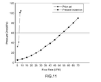
- FIGS. 11 and 12 are graphs comparing the performance of the demineralizer in accordance with the present invention with that of a conventional demineralizer (i.e., a hollow demineralizer), in which FIG. 11 shows the comparison results of pressure drop and FIG. 12 shows the measurement results of filtering efficiency.
- a conventional demineralizer i.e., a hollow demineralizer
- the pressure drop (i.e., differential pressure) can be considerably reduced compared to the conventional demineralizer using the hollow filter member as well as the demineralizer of FIGS. 2 to 4 .
- FIG. 11 it can be seen that the occurrence of differential pressure due to the ion resin layer is clearly reduced in the demineralizer of the present invention compared to the conventional demineralizer. This shows in turn that the flow rate of coolant can be increased in the demineralizer of the present invention under the same differential pressure compared to the conventional demineralizer.
- the flow of the coolant passing through the demineralizer is suitably distributed, which increases the filtering efficiency, thereby rapidly reduces the electrical conductivity of the coolant.
- FIG. 12 shows the effect of reducing the electrical conductivity during the initial start-up when the demineralizer of the present invention and the conventional (hollow) demineralizer are used, in which the amount of time that the initial electrical conductivity is reduced from about 120 ⁇ S/cm to less than about 1 ⁇ S/cm under the same conditions (the same ion resin, the same pump pressure, and the same number of facilities) is shown.
- the occurrence of differential pressure is suitably reduced and the reduction in the electrical conductivity is improved in the demineralizer of the present invention and that the amount of time required to reach the electrical conductivity of less than 1 ⁇ S/cm during initial start-up is considerably reduced compared to the demineralizers according to the prior art and the comparative example.
- Ion release occurs in all the components that constitute the coolant loop after parking for a predetermined time such as on weekends, etc., and thus the electrical conductivity of the coolant typically increases (for example, from the range of about 0.5 to 2 ⁇ S/cm to the range of about 5 to 8 ⁇ S/cm). It can be seen from the results of FIG. 12 that the electrical conductivity of the coolant is reduced to a normal value (i.e., less than 2 ⁇ S/cm) after start-up in the demineralizer of the present invention in significantly less time than in the comparative example.
- the large-area demineralizer of the present invention since the coolant passes through the plate-shaped filter member in a direction perpendicular to the filter member, the occurrence of differential pressure is reduced and the flow of coolant is uniformly distributed, thereby maximizing the effect of filtering ions.
- the position and arrangement of the inlet and outlet ports are optimized such that the flow of coolant is uniformly distributed over the entire region of the filter member, and thus it is possible to maximize the utilization of the ion resin and the effect of filtering ions and reduce the manufacturing and maintenance costs.
Landscapes
- Engineering & Computer Science (AREA)
- Chemical Kinetics & Catalysis (AREA)
- Chemical & Material Sciences (AREA)
- Sustainable Energy (AREA)
- Sustainable Development (AREA)
- Life Sciences & Earth Sciences (AREA)
- Manufacturing & Machinery (AREA)
- Electrochemistry (AREA)
- General Chemical & Material Sciences (AREA)
- Power Engineering (AREA)
- Transportation (AREA)
- Mechanical Engineering (AREA)
- Fuel Cell (AREA)
Abstract
Description
Claims (3)
Applications Claiming Priority (2)
| Application Number | Priority Date | Filing Date | Title |
|---|---|---|---|
| KR10-2011-0057079 | 2011-06-13 | ||
| KR1020110057079A KR101272593B1 (en) | 2011-06-13 | 2011-06-13 | De-Mineralizer for fuel cell |
Publications (2)
| Publication Number | Publication Date |
|---|---|
| US20120315563A1 US20120315563A1 (en) | 2012-12-13 |
| US9105886B2 true US9105886B2 (en) | 2015-08-11 |
Family
ID=47220468
Family Applications (1)
| Application Number | Title | Priority Date | Filing Date |
|---|---|---|---|
| US13/272,689 Active 2033-06-22 US9105886B2 (en) | 2011-06-13 | 2011-10-13 | Large-area demineralizer for fuel cell |
Country Status (4)
| Country | Link |
|---|---|
| US (1) | US9105886B2 (en) |
| KR (1) | KR101272593B1 (en) |
| CN (1) | CN102832400B (en) |
| DE (1) | DE102011085222B4 (en) |
Families Citing this family (7)
| Publication number | Priority date | Publication date | Assignee | Title |
|---|---|---|---|---|
| KR101350188B1 (en) * | 2011-11-18 | 2014-01-09 | 기아자동차주식회사 | Ion filter for fuel cell system |
| US9357674B2 (en) * | 2013-12-18 | 2016-05-31 | International Business Machines Corporation | Liquid-cooling apparatus with integrated coolant filter |
| KR101633801B1 (en) * | 2014-11-04 | 2016-06-27 | 말레동현필터시스템 주식회사 | Measuring kit for remaining life of ion filter and large area ion filter for hydrogen fuel vehicle having the same |
| DE102016108866B4 (en) | 2016-05-13 | 2019-10-24 | Iav Gmbh Ingenieurgesellschaft Auto Und Verkehr | Modular ion exchanger |
| DE102017209968A1 (en) * | 2017-06-13 | 2018-12-13 | Audi Ag | Ion filter mount |
| DE102018219201A1 (en) | 2018-11-12 | 2020-05-14 | Audi Ag | Fuel cell device |
| KR102638605B1 (en) * | 2021-12-07 | 2024-02-21 | 주식회사 케이퓨얼셀 | Ion filter apparatus for fuel cell vehicle |
Citations (8)
| Publication number | Priority date | Publication date | Assignee | Title |
|---|---|---|---|---|
| KR20020032684A (en) | 2000-10-26 | 2002-05-04 | 이계안 | System of purifying water for fuel cell system |
| JP2002298885A (en) | 2001-03-30 | 2002-10-11 | Nissan Motor Co Ltd | Fuel cell system |
| US20040001985A1 (en) * | 2002-06-28 | 2004-01-01 | Hydrogenics Corporation | Fuel cell cooling system |
| US20050115884A1 (en) * | 2003-11-28 | 2005-06-02 | Toyo Roki Seizo Kabushiki Kaisha | Ion-exchange filter |
| JP2007296419A (en) | 2006-04-27 | 2007-11-15 | Toshiba Corp | Ion filter and fuel cell device provided with the same |
| KR20080053939A (en) | 2005-10-01 | 2008-06-16 | 칼 프로이덴베르크 카게 | Filter unit |
| JP2009123518A (en) | 2007-11-15 | 2009-06-04 | Toyota Motor Corp | Fuel cell system |
| KR20110061731A (en) | 2009-12-02 | 2011-06-10 | 현대자동차주식회사 | Coolant Ion Filter for Fuel Cell Vehicle |
Family Cites Families (3)
| Publication number | Priority date | Publication date | Assignee | Title |
|---|---|---|---|---|
| JP4839590B2 (en) * | 2004-09-06 | 2011-12-21 | トヨタ自動車株式会社 | Fuel cell system |
| KR20100061731A (en) | 2007-09-14 | 2010-06-08 | 퀄컴 엠이엠스 테크놀로지스, 인크. | Etching processes used in mems production |
| KR20110045403A (en) * | 2009-10-26 | 2011-05-04 | 현대자동차주식회사 | Coolant Ion Filter for Fuel Cell Vehicle |
-
2011
- 2011-06-13 KR KR1020110057079A patent/KR101272593B1/en not_active Expired - Fee Related
- 2011-10-13 US US13/272,689 patent/US9105886B2/en active Active
- 2011-10-26 DE DE102011085222.0A patent/DE102011085222B4/en active Active
- 2011-10-28 CN CN201110335486.0A patent/CN102832400B/en active Active
Patent Citations (8)
| Publication number | Priority date | Publication date | Assignee | Title |
|---|---|---|---|---|
| KR20020032684A (en) | 2000-10-26 | 2002-05-04 | 이계안 | System of purifying water for fuel cell system |
| JP2002298885A (en) | 2001-03-30 | 2002-10-11 | Nissan Motor Co Ltd | Fuel cell system |
| US20040001985A1 (en) * | 2002-06-28 | 2004-01-01 | Hydrogenics Corporation | Fuel cell cooling system |
| US20050115884A1 (en) * | 2003-11-28 | 2005-06-02 | Toyo Roki Seizo Kabushiki Kaisha | Ion-exchange filter |
| KR20080053939A (en) | 2005-10-01 | 2008-06-16 | 칼 프로이덴베르크 카게 | Filter unit |
| JP2007296419A (en) | 2006-04-27 | 2007-11-15 | Toshiba Corp | Ion filter and fuel cell device provided with the same |
| JP2009123518A (en) | 2007-11-15 | 2009-06-04 | Toyota Motor Corp | Fuel cell system |
| KR20110061731A (en) | 2009-12-02 | 2011-06-10 | 현대자동차주식회사 | Coolant Ion Filter for Fuel Cell Vehicle |
Non-Patent Citations (2)
| Title |
|---|
| JP 2007-296419-MT. * |
| KR 1020000063120-MT. * |
Also Published As
| Publication number | Publication date |
|---|---|
| US20120315563A1 (en) | 2012-12-13 |
| DE102011085222B4 (en) | 2024-08-22 |
| DE102011085222A1 (en) | 2012-12-13 |
| KR101272593B1 (en) | 2013-06-11 |
| KR20120137914A (en) | 2012-12-24 |
| CN102832400B (en) | 2016-06-01 |
| CN102832400A (en) | 2012-12-19 |
Similar Documents
| Publication | Publication Date | Title |
|---|---|---|
| US8518254B2 (en) | Coolant demineralizer for a fuel cell vehicle | |
| US9105886B2 (en) | Large-area demineralizer for fuel cell | |
| US8709251B2 (en) | Coolant demineralizer for fuel cell vehicle | |
| US9981693B2 (en) | Fuel cell vehicle | |
| KR101592391B1 (en) | Hydrogen supply apparatus of fuel cell stack | |
| US9079508B2 (en) | Fuel cell vehicle | |
| US9543610B2 (en) | Fuel cell vehicle | |
| US9653744B2 (en) | Method of starting fuel cell system for vehicle and fuel cell system | |
| JP6547769B2 (en) | Fuel cell vehicle | |
| JP5860472B2 (en) | Ion exchanger and cooling device provided with ion exchanger | |
| US20170113531A1 (en) | Fuel cell vehicle | |
| US20170187050A1 (en) | Fuel cell unit including an exchangeable deionization device and a vehicle including such a fuel cell unit | |
| US20120141896A1 (en) | Fuel cell system and method of controlling the same | |
| CN111987329A (en) | Fuel cell stack | |
| CA2787237A1 (en) | Fuel-cell-powered vehicle | |
| US20120145280A1 (en) | Apparatus for injecting coolant for fuel cell vehicle | |
| JP5508915B2 (en) | Fuel cell system | |
| US20150180069A1 (en) | Apparatus and method for controlling hydrogen purging | |
| JP5168980B2 (en) | Fuel cell device | |
| KR101601377B1 (en) | A heat exchange unit of suppling air to fuel cell cathod and a heat exchange method thereof | |
| US20240113309A1 (en) | Fuel cell system | |
| KR101745000B1 (en) | Ion filter having buffer zone for fuel cell system | |
| CN120854602A (en) | Fuel cell systems and vehicles | |
| US20180062189A1 (en) | Coolant heater | |
| JP2007032757A (en) | Gas storage tank |
Legal Events
| Date | Code | Title | Description |
|---|---|---|---|
| AS | Assignment |
Owner name: KIA MOTORS CORPORATION, KOREA, REPUBLIC OF Free format text: ASSIGNMENT OF ASSIGNORS INTEREST;ASSIGNORS:NA, SUNG WOOK;PARK, HUN WOO;REEL/FRAME:027057/0097 Effective date: 20110816 Owner name: HYUNDAI MOTOR COMPANY, KOREA, REPUBLIC OF Free format text: ASSIGNMENT OF ASSIGNORS INTEREST;ASSIGNORS:NA, SUNG WOOK;PARK, HUN WOO;REEL/FRAME:027057/0097 Effective date: 20110816 |
|
| STCF | Information on status: patent grant |
Free format text: PATENTED CASE |
|
| FEPP | Fee payment procedure |
Free format text: PAYER NUMBER DE-ASSIGNED (ORIGINAL EVENT CODE: RMPN); ENTITY STATUS OF PATENT OWNER: LARGE ENTITY Free format text: PAYOR NUMBER ASSIGNED (ORIGINAL EVENT CODE: ASPN); ENTITY STATUS OF PATENT OWNER: LARGE ENTITY |
|
| MAFP | Maintenance fee payment |
Free format text: PAYMENT OF MAINTENANCE FEE, 4TH YEAR, LARGE ENTITY (ORIGINAL EVENT CODE: M1551); ENTITY STATUS OF PATENT OWNER: LARGE ENTITY Year of fee payment: 4 |
|
| MAFP | Maintenance fee payment |
Free format text: PAYMENT OF MAINTENANCE FEE, 8TH YEAR, LARGE ENTITY (ORIGINAL EVENT CODE: M1552); ENTITY STATUS OF PATENT OWNER: LARGE ENTITY Year of fee payment: 8 |