US9091858B2 - Display apparatus and method of displaying three dimensional image using the same - Google Patents
Display apparatus and method of displaying three dimensional image using the same Download PDFInfo
- Publication number
- US9091858B2 US9091858B2 US13/362,379 US201213362379A US9091858B2 US 9091858 B2 US9091858 B2 US 9091858B2 US 201213362379 A US201213362379 A US 201213362379A US 9091858 B2 US9091858 B2 US 9091858B2
- Authority
- US
- United States
- Prior art keywords
- display panel
- image
- unit pixel
- opening portion
- width
- Prior art date
- Legal status (The legal status is an assumption and is not a legal conclusion. Google has not performed a legal analysis and makes no representation as to the accuracy of the status listed.)
- Active, expires
Links
Images


Classifications
-
- G02B27/2214—
-
- H—ELECTRICITY
- H04—ELECTRIC COMMUNICATION TECHNIQUE
- H04N—PICTORIAL COMMUNICATION, e.g. TELEVISION
- H04N13/00—Stereoscopic video systems; Multi-view video systems; Details thereof
- H04N13/30—Image reproducers
- H04N13/302—Image reproducers for viewing without the aid of special glasses, i.e. using autostereoscopic displays
- H04N13/305—Image reproducers for viewing without the aid of special glasses, i.e. using autostereoscopic displays using lenticular lenses, e.g. arrangements of cylindrical lenses
-
- G—PHYSICS
- G02—OPTICS
- G02B—OPTICAL ELEMENTS, SYSTEMS OR APPARATUS
- G02B30/00—Optical systems or apparatus for producing three-dimensional [3D] effects, e.g. stereoscopic images
- G02B30/20—Optical systems or apparatus for producing three-dimensional [3D] effects, e.g. stereoscopic images by providing first and second parallax images to an observer's left and right eyes
- G02B30/26—Optical systems or apparatus for producing three-dimensional [3D] effects, e.g. stereoscopic images by providing first and second parallax images to an observer's left and right eyes of the autostereoscopic type
- G02B30/27—Optical systems or apparatus for producing three-dimensional [3D] effects, e.g. stereoscopic images by providing first and second parallax images to an observer's left and right eyes of the autostereoscopic type involving lenticular arrays
-
- G—PHYSICS
- G02—OPTICS
- G02B—OPTICAL ELEMENTS, SYSTEMS OR APPARATUS
- G02B30/00—Optical systems or apparatus for producing three-dimensional [3D] effects, e.g. stereoscopic images
- G02B30/20—Optical systems or apparatus for producing three-dimensional [3D] effects, e.g. stereoscopic images by providing first and second parallax images to an observer's left and right eyes
- G02B30/26—Optical systems or apparatus for producing three-dimensional [3D] effects, e.g. stereoscopic images by providing first and second parallax images to an observer's left and right eyes of the autostereoscopic type
- G02B30/30—Optical systems or apparatus for producing three-dimensional [3D] effects, e.g. stereoscopic images by providing first and second parallax images to an observer's left and right eyes of the autostereoscopic type involving parallax barriers
- G02B30/32—Optical systems or apparatus for producing three-dimensional [3D] effects, e.g. stereoscopic images by providing first and second parallax images to an observer's left and right eyes of the autostereoscopic type involving parallax barriers characterised by the geometry of the parallax barriers, e.g. staggered barriers, slanted parallax arrays or parallax arrays of varying shape or size
-
- G—PHYSICS
- G09—EDUCATION; CRYPTOGRAPHY; DISPLAY; ADVERTISING; SEALS
- G09G—ARRANGEMENTS OR CIRCUITS FOR CONTROL OF INDICATING DEVICES USING STATIC MEANS TO PRESENT VARIABLE INFORMATION
- G09G3/00—Control arrangements or circuits, of interest only in connection with visual indicators other than cathode-ray tubes
- G09G3/001—Control arrangements or circuits, of interest only in connection with visual indicators other than cathode-ray tubes using specific devices not provided for in groups G09G3/02 - G09G3/36, e.g. using an intermediate record carrier such as a film slide; Projection systems; Display of non-alphanumerical information, solely or in combination with alphanumerical information, e.g. digital display on projected diapositive as background
- G09G3/003—Control arrangements or circuits, of interest only in connection with visual indicators other than cathode-ray tubes using specific devices not provided for in groups G09G3/02 - G09G3/36, e.g. using an intermediate record carrier such as a film slide; Projection systems; Display of non-alphanumerical information, solely or in combination with alphanumerical information, e.g. digital display on projected diapositive as background to produce spatial visual effects
-
- G—PHYSICS
- G09—EDUCATION; CRYPTOGRAPHY; DISPLAY; ADVERTISING; SEALS
- G09G—ARRANGEMENTS OR CIRCUITS FOR CONTROL OF INDICATING DEVICES USING STATIC MEANS TO PRESENT VARIABLE INFORMATION
- G09G3/00—Control arrangements or circuits, of interest only in connection with visual indicators other than cathode-ray tubes
- G09G3/20—Control arrangements or circuits, of interest only in connection with visual indicators other than cathode-ray tubes for presentation of an assembly of a number of characters, e.g. a page, by composing the assembly by combination of individual elements arranged in a matrix no fixed position being assigned to or needed to be assigned to the individual characters or partial characters
- G09G3/34—Control arrangements or circuits, of interest only in connection with visual indicators other than cathode-ray tubes for presentation of an assembly of a number of characters, e.g. a page, by composing the assembly by combination of individual elements arranged in a matrix no fixed position being assigned to or needed to be assigned to the individual characters or partial characters by control of light from an independent source
- G09G3/3406—Control of illumination source
-
- H04N13/0404—
-
- H—ELECTRICITY
- H04—ELECTRIC COMMUNICATION TECHNIQUE
- H04N—PICTORIAL COMMUNICATION, e.g. TELEVISION
- H04N13/00—Stereoscopic video systems; Multi-view video systems; Details thereof
- H04N13/30—Image reproducers
- H04N13/332—Displays for viewing with the aid of special glasses or head-mounted displays [HMD]
- H04N13/341—Displays for viewing with the aid of special glasses or head-mounted displays [HMD] using temporal multiplexing
Definitions
- Exemplary embodiments of the invention relate to a display apparatus and a method of displaying a three dimensional (“3D”) image using the display apparatus. More particularly, exemplary embodiments of the invention relate to a display apparatus improving a display quality and a method of displaying a 3D image using the display apparatus.
- 3D three dimensional
- a liquid crystal display apparatus displays a two dimensional (“2D”) image.
- 2D two dimensional
- a stereoscopic image display apparatus displays the 3D image using a binocular parallax between two eyes of a human. For example, as two eyes of a human are spaced apart from each other, images viewed at different angles are inputted to a human brain. The human brain mixes the images so that an observer may recognize the stereoscopic image.
- the stereoscopic image display device may be divided into a stereoscopic type and an auto-stereoscopic type depending on whether a view wears an extra spectacle or not.
- the stereoscopic type may include an anaglyph type and a shutter glass type and so on.
- anaglyph type blue glasses and red glasses may be required for the viewer to wear.
- the shutter glass type a left image and a right image may be temporally divided to be periodically displayed, and a viewer wears glasses which opens and closes a left eye shutter and a right eye shutter in synchronization with the period of the left and right images.
- the auto-stereoscopic type may include a lenticular type.
- a lenticular type a lenticular lens having a plurality of focal points is used.
- the 2D image is refracted by the lenticular lens at the focal points so that the 3D image is displayed.
- a resolution of the liquid crystal display apparatus is decreased so that the display quality may be deteriorated.
- a crosstalk which means that a left image is shown in a right eye or a right image is shown in a left eye, may occur.
- a moiré which means that a luminance of a display panel is not uniform according to a position in the display panel, also may occur.
- Exemplary embodiments of the invention provide a display apparatus to improve a display quality of a three dimensional (“3D”) image.
- 3D three dimensional
- Exemplary embodiments of the invention also provide a method of displaying the 3D image using the display apparatus.
- the display apparatus includes a display panel, a lens plate and a lens driver.
- the display panel includes a plurality of unit pixels.
- the display panel is driven by dividing a single frame into N sub frames. N is a natural number.
- the lens plate is on the display panel.
- the lens plate includes a plurality of lenses converting a two dimensional (“2D”) image displayed on the display panel into a 3D image.
- the lens driver disposes the lenses at a first position during a first sub frame.
- the lens driver moves the lenses to a second position from the first position and disposes the lenses at the second position during a second sub frame.
- the second position is shifted by 1/N of a width of the unit pixel from the first position.
- a unit pixel may include an opening portion and a blocking portion.
- An aperture ratio of the unit pixel which is defined as a ratio of a width of the opening portion to the width of the unit pixel, may be 1/N.
- the opening portion and the blocking portion may alternate in a horizontal direction of the display panel.
- the opening portion and the blocking portion may alternate in a vertical direction of the display panel.
- the opening portion and the blocking portion may alternate in a horizontal direction of the display panel.
- a group of the opening portions and a group of the blocking portions may alternate in a vertical direction of the display panel.
- the display panel may further include a color filter in the opening portion, and a black matrix in the blocking portion.
- the display apparatus may further includes a barrier part between the display panel and the lens plate.
- the barrier part may include a plurality of barriers.
- the display panel may further include a color filter in the opening portion of the unit pixel.
- a barrier may overlap the blocking portion of the unit pixel.
- an extending direction of the lens may be substantially parallel to a longitudinal direction of the unit pixel.
- a moving direction of the lenses may be substantially perpendicular to the extending direction of the lens.
- a width of the lens may correspond to a total width of the unit pixels.
- the lens plate may be a liquid crystal lens panel.
- the lens may be an electric field applied to the liquid crystal lens panel.
- the display apparatus includes a display panel, a lens plate, an active barrier part and a barrier driver.
- the display panel includes a plurality of unit pixels.
- the display panel is driven by dividing a single frame into N sub frames. N is a natural number.
- the lens plate is on the display panel.
- the lens plate includes a plurality of lenses converting a 2D image displayed on the display panel into a 3D image.
- the active barrier part is between the display panel and the lens plate.
- the active barrier part includes a plurality of active barriers.
- the barrier driver disposes the active barriers at a first position during a first sub frame.
- the barrier driver moves the active barriers to a second position from the first position and disposes the active barriers at the second position during a second sub frame. The second position is shifted by 1/N of a width of the unit pixel from the first position.
- a unit pixel may include an opening portion and a blocking portion.
- An aperture ratio of the unit pixel which is defined as a ratio of a width of the opening portion to the width of the unit pixel, may be 1/N.
- the display panel may include a color filter in the opening portion of the unit pixel.
- An active barrier may overlap the blocking portion of the unit pixel.
- the method includes providing a first image to a display panel during a first sub frame and a second image to the display panel during a second sub frame, disposing a plurality of lenses at a first position during the first sub frame, the lenses converting the first image into a first 3D image, and moving the lenses to a second position from the first position and disposing the lenses at the second position during the second sub frame, the lenses converting the second image into a second 3D image.
- the display panel includes a plurality of unit pixels. The display panel is driven by dividing a single frame into N sub frames. N is a natural number. The lenses are on the display panel. The second position is shifted by 1/N of a width of the unit pixel from the first position.
- a unit pixel may include an opening portion and a blocking portion.
- An aperture ratio of the unit pixel which is defined as a ratio of a width of the opening portion to the width of the unit pixel, may be 1/N.
- the display panel may include a color filter in the opening portion, and a black matrix in the blocking portion
- a barrier part may be between the display panel and the lens plate.
- the barrier part may include a plurality of barriers.
- the display panel may further include a color filter in the opening portion of the unit pixel.
- a barrier may overlap the blocking portion of the unit pixel.
- the method includes providing a first image to a display panel during a first sub frame and a second image to the display panel during a second sub frame, disposing a plurality of active barriers at a first position during the first sub frame, such that the first image is converted into a first 3D image, and moving the active barriers to a second position from the first position and disposing the active barriers at the second position during the second sub frame, such that the second image is converted into a second 3D image.
- the display panel includes a plurality of unit pixels. The display panel is driven by dividing a single frame into N sub frames. N is a natural number.
- the active barriers are between the display panel, and a plurality of lenses on the display panel. The second position is shifted by 1/N of a width of the unit pixel from the first position.
- a unit pixel may include an opening portion and a blocking portion.
- An aperture ratio of the unit pixel which is defined as a ratio of a width of the opening portion to the width of the unit pixel, may be 1/N.
- the display panel may include a color filter in the opening portion of the unit pixel.
- An active barrier may overlap the blocking portion of the unit pixel.
- a display panel may be driven in a temporal dividing method using a lens or active barrier which moves according to a sub frame.
- the number of viewpoints of the 3D image may be increased so that the display quality of the 3D image may be improved.
- FIG. 1 is a perspective view illustrating an exemplary embodiment of a display apparatus according to the invention
- FIG. 2 is a plan view illustrating an exemplary embodiment of a display panel of FIG. 1 ;
- FIG. 3 is a plan view illustrating an exemplary embodiment of a unit pixel of FIG. 1 ;
- FIG. 4A is a cross-sectional view illustrating an exemplary embodiment of a relative position of the display panel and a lens plate of FIG. 1 during a first sub frame;
- FIG. 4B is a cross-sectional view illustrating an exemplary embodiment of a relative position of the display panel and the lens plate of FIG. 1 during a second sub frame;
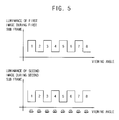
- FIG. 5 is a graph illustrating a luminance of the display panel of FIG. 1 according to a viewing angle during the first and second sub frames;
- FIG. 6 is a plan view illustrating another exemplary embodiment of a display panel of a display apparatus according to the invention.
- FIG. 7 is a plan view illustrating still another exemplary embodiment of a display panel of a display apparatus according to the invention.
- FIG. 8 is a perspective view illustrating another exemplary embodiment of a display apparatus according to the invention.
- FIG. 9A is a cross-sectional view illustrating an exemplary embodiment of a relative position of a display panel, a barrier part and a lens plate of FIG. 8 during a first sub frame;
- FIG. 9B is a cross-sectional view illustrating an exemplary embodiment of a relative position of the display panel, the barrier part and the lens plate of FIG. 8 during a second sub frame;
- FIG. 10 is a perspective view illustrating still another exemplary embodiment of a display apparatus according to the invention.
- FIG. 11A is a cross-sectional view illustrating an exemplary embodiment of a relative position of a display panel, an active barrier part and a lens plate of FIG. 10 during a first sub frame;
- FIG. 11B is a cross-sectional view illustrating an exemplary embodiment of a relative position of the display panel, the active barrier part and the lens plate of FIG. 10 during a second sub frame;
- FIG. 12 is a plan view illustrating another exemplary embodiment of a unit pixel of a display panel of a display apparatus according to the invention.
- FIG. 13A is a cross-sectional view illustrating an exemplary embodiment of a relative position of the display panel including the unit pixel of FIG. 12 and a lens plate during a first sub frame;
- FIG. 13B is a cross-sectional view illustrating an exemplary embodiment of a relative position of the display panel including the unit pixel of FIG. 12 and the lens plate during a second sub frame;
- FIG. 13C is a cross-sectional view illustrating an exemplary embodiment of a relative position of the display panel including the unit pixel of FIG. 12 and the lens plate during a third sub frame;
- FIG. 14 is a graph illustrating a luminance of the display panel including the unit pixel of FIG. 12 according to a viewing angle during the first to third sub frames.
- first, second, third, etc. may be used herein to describe various elements, components, regions, layers and/or sections, these elements, components, regions, layers and/or sections should not be limited by these terms. These terms are only used to distinguish one element, component, region, layer or section from another region, layer or section. Thus, a first element, component, region, layer or section discussed below could be termed a second element, component, region, layer or section without departing from the teachings of the invention.
- FIG. 1 is a perspective view illustrating an exemplary embodiment of a display apparatus according to the invention.
- FIG. 2 is a plan view illustrating a display panel 100 of FIG. 1 .
- the display apparatus includes the display panel 100 , a lens plate 200 , a display panel driver 300 and a lens driver 400 .
- the display panel 100 displays an image.
- the display panel 100 includes a plurality of unit pixels UP.
- the unit pixels UP may be in a matrix form.
- the unit pixels UP are adjacent to each other in a first direction D 1 to form a pixel row.
- the unit pixels UP are adjacent to each other in a second direction D 2 crossing the first direction D 1 to form a pixel column.
- the second direction D 2 may be substantially perpendicular to the first direction D 1 .
- a first pixel row includes a plurality of red pixels R.
- a second pixel row adjacent to the first pixel row includes a plurality of green pixels G.
- a third pixel row adjacent to the second pixel row includes a plurality of blue pixels B.
- the first to third pixel rows may include the red, green and blue pixels R, G and B which alternate with each other in the first direction D 1 .
- First to fourth pixel columns PC 1 , PC 2 , PC 3 and PC 4 respectively include the red, green and blue pixels R, G and B which alternate with each other in the second direction D 2 .
- the first to fourth pixel columns PC 1 , PC 2 , PC 3 and PC 4 may respectively include a single colored pixel.
- a relatively long side of the unit pixel UP extends in the second direction D 2 and a relatively short side of the unit pixel UP extends in the first direction D 1 in the illustrated exemplary embodiment.
- a relatively long side of the unit pixel UP may extend in the first direction D 1 and a relatively short side of the unit pixel UP may extend in the second direction D 2 .
- the display panel 100 may include a first substrate (not shown), a second substrate (not shown) and a liquid crystal layer (not shown) between the first and second substrates.
- the first substrate may include a pixel electrode (not shown), a gate line (not shown) and a data line (not shown).
- the second substrate may include a common electrode (not shown) and a color filter (not shown).
- the lens plate 200 is on the display panel 100 , such as on a viewing or emitting side of the display panel 100 .
- the lens plate 200 includes a plurality of lenses L.
- the lenses L convert a 2D image displayed on the display panel 100 to a 3D image.
- the lenses L longitudinally extend along the second direction D 2 , and are adjacent to each other in the first direction D 1 .
- An extending direction of the lens L may be parallel to a vertical (e.g., long) direction of the unit pixel UP.
- a width of the lens L in the first direction D 1 may correspond to a width of the unit pixels UP in the first direction D 1 .
- the width of the lens L in the first direction D 1 may be substantially equal to a total width of four unit pixels UP in the first direction D 1 .
- the number of the viewpoints of the 3D image may be four.
- the width of the lens L in the first direction D 1 may be substantially equal to a total width of nine unit pixels UP in the first direction D 1 .
- the number of the viewpoints of the 3D image may be nine.
- the lenses L may have a convex shape protruding from a planar portion of the lens plate 200 toward an upper direction.
- the lens plate 200 may be a liquid crystal lens panel driven by an electric field.
- the lenses L do not physically have a convex shape.
- Optical characteristics of the lenses L are electrically defined by the electric field applied to the liquid crystal lens panel.
- the display panel driver 300 is connected to the display panel 100 .
- the display panel driver 300 outputs a signal for driving the display panel 100 , to the display panel 100 .
- the display panel driver 300 drives the display panel 100 by dividing a single frame into N sub frames.
- N is a natural number.
- the display panel driver 300 when N is two, the display panel driver 300 generates a first image corresponding to a first sub frame and a second image corresponding to a second sub frame, based on an input image.
- the display panel driver 300 provides the first image to the display panel 100 during the first sub frame.
- the display panel driver 300 provides the second image to the display panel 100 during the second sub frame.
- the first image may be a left image
- the second image may be a right image.
- the width of the lens L in the first direction D 1 is equal to a total width of four unit pixels UP in the first direction D 1 , the number of viewpoints increases to four by the lens L, and the number of viewpoints increases to eight by the temporal dividing driving method.
- the display panel driver 300 includes a timing controller (not shown), a gate driver (not shown) and a data driver (not shown).
- the timing controller generates driving signals to control driving timings of the gate driver and the data driver.
- the gate driver generates a gate signal in response to the driving signals.
- the gate driver outputs the gate signal to the gate line of the display panel 100 .
- the data driver generates a data voltage in response to the driving signals.
- the data driver outputs the data voltage to the data line of the display panel 100 .
- the display panel driver 300 may further include a frame rate converter (not shown) to convert a frame rate of the input image.
- the lens driver 400 is connected to the lens plate 200 .
- the lens driver 400 outputs a signal for driving the lenses L.
- the lens driver 400 disposes the lenses L at a first position during the first sub frame.
- the lens driver 400 disposes the lenses L at a second position during the second sub frame.
- the second position is shifted by 1/N of the width of the unit pixel UP from the first position.
- the lens driver 400 moves the lenses L by a half of the width of the unit pixel UP to dispose the lenses L at the second position during the second sub frame.
- the lens driver 400 may physically move the lens plate 200 .
- the lens driver 400 does not physically move the lens plate 200 .
- the lens plate 200 is driven as the lenses L move.
- FIG. 3 is a plan view illustrating an exemplary embodiment of the unit pixel UP of FIG. 1 .
- the unit pixel UP includes an opening portion OP and a blocking portion BP.
- the blocking portion BP may be adjacent to the opening portion OP in the first direction D 1 .
- the opening portion OP is defined by the color filter of the display panel 100 .
- the blocking portion BP is defined by a black matrix of the display panel 100 .
- the color filter is in the opening portion OP.
- the black matrix is in the blocking portion BP.
- the opening portion OP has a first width W 1 in the first direction D 1 .
- the blocking portion BP has a second width W 2 in the first direction D 1 .
- the width W of the unit pixel UP in the first direction D 1 is substantially equal to a sum of the first and second widths W 1 +W 2 .
- An aperture ratio of the unit pixel UP is defined as a ratio of an area of the opening portion OP to an area of the unit pixel UP.
- the aperture ratio of the unit pixel UP may be defined as a ratio of the first width W 1 of the opening portion OP to the width W of the unit pixel UP.
- N is two, so that the aperture ratio W 1 /W is 1 ⁇ 2.
- a ratio between the first width W 1 of the opening portion OP and the second width W 2 of the blocking portion BP is 1:1.
- FIG. 4A is a cross-sectional view illustrating an exemplary embodiment of a relative position of the display panel 100 and the lens plate 200 of FIG. 1 during the first sub frame.
- FIG. 4B is a cross-sectional view illustrating an exemplary embodiment of a relative position of the display panel 100 and the lens plate 200 of FIG. 1 during the second sub frame.
- the display panel 100 includes first to fourth pixels P 1 , P 2 , P 3 and P 4 .
- a width of each of the first to fourth pixels P 1 to P 4 is W.
- An aperture ratio of each of the first to fourth pixels P 1 to P 4 is 1 ⁇ 2.
- the lens plate 200 is on the display panel 100 .
- a single lens of the lens plate 200 has a width corresponding to a total width of four pixels.
- the lens has a width corresponding to a total width of the first to fourth pixels P 1 to P 4 .
- the display panel driver 300 provides the first image to the display panel 100 during the first sub frame.
- the first image includes first, third, fifth and seventh viewpoint images 1 , 3 , 5 and 7 .
- the first pixel P 1 displays the first viewpoint image 1 .
- the second pixel P 2 displays the third viewpoint image 3 .
- the third pixel P 3 displays the fifth viewpoint image 5 .
- the fourth pixel P 4 displays the seventh viewpoint image 7 .
- the lens driver 400 disposes the lens at the first position, which corresponds to a boundary of the first pixel P 1 and a boundary of the fourth pixel P 4 .
- the display panel driver 300 provides the second image to the display panel 100 during the second sub frame.
- the second image includes second, fourth, sixth and eighth viewpoint images 2 , 4 , 6 and 8 .
- the first pixel P 1 displays the second viewpoint image 2 .
- the second pixel P 2 displays the fourth viewpoint image 4 .
- the third pixel P 3 displays the sixth viewpoint image 6 .
- the fourth pixel P 4 displays the eighth viewpoint image 8 .
- the lens driver 400 moves the lens to the second position from the first position to dispose the lens at the second position.
- the second position is shifted by a half of the width of the unit pixel W/2 from the first position.
- the first viewpoint image 1 is viewed to the left eye of the observer through the opening portion during the first sub frame.
- a black image is viewed to the right eye of the observer by the blocking portion during the first sub frame.
- the second viewpoint image 2 is viewed to the right eye of the observer through the opening portion during the second sub frame.
- a black image is viewed to the left eye of the observer by the blocking portion during the second sub frame.
- the observer may recognize the 3D image by mixing the first viewpoint image 1 of the first sub frame and the second viewpoint image 2 of the second sub frame.
- the third viewpoint image 3 is viewed to the right eye of the observer through the opening portion during the first sub frame.
- a black image is viewed to the left eye of the observer by the blocking portion during the first sub frame.
- the second viewpoint image 2 is viewed to the left eye of the observer through the opening portion during the second sub frame.
- a black image is viewed to the right eye of the observer by the blocking portion during the second sub frame.
- the observer may recognize the 3D image by mixing the third viewpoint image 3 of the first sub frame and the second viewpoint image 2 of the second sub frame.
- FIG. 5 is a graph illustrating a luminance of the display panel 100 of FIG. 1 according to a viewing angle during the first and second sub frames.
- relatively bright images are viewed at the first, third, fifth and seventh viewpoints through the opening portion during the first sub frame.
- the black images are viewed at the second, fourth, sixth and eighth viewpoints by the blocking portion during the first sub frame.
- Relatively bright images are viewed at the second, fourth, sixth and eighth viewpoints through the opening portion during the second sub frame.
- the black images are viewed at the first, third, fifth and seventh viewpoints by the blocking portion during the second sub frame.
- the display apparatus of the illustrated exemplary embodiment displays the 3D image like a display apparatus using a shutter glass.
- the display apparatus of the illustrated exemplary embodiment may reduce or effectively prevent crosstalk where a left image is shown in a right eye or a right image is shown in a left eye.
- an average of a luminance of the first image during the first sub frame and a luminance of the second image during the second sub frame is substantially uniform at any viewpoints, so that the display apparatus of the illustrated exemplary embodiment may reduce or effectively prevent the moiré where a luminance of the display panel 100 is not uniform according to the viewpoint.
- P viewpoints may be generated by the lens
- N viewpoints may be generated by the temporal dividing driving method so that P ⁇ N viewpoints of the display apparatus may be generated.
- the display quality of the 3D image and the viewing angle of the display apparatus may be improved.
- the aperture of the unit pixel is adjusted according to the temporal dividing driving method so that the crosstalk and the moiré may be reduced or effectively prevented.
- the display quality of the 3D image may be improved.
- FIG. 6 is a plan view illustrating another exemplary embodiment of a display panel of a display apparatus according to the invention.
- a display apparatus and a method of displaying a 3D image according to the illustrated exemplary embodiment is substantially the same as the display apparatus and the method of displaying the 3D image of the previous exemplary embodiment explained referring to FIGS. 1 to 5 except for a pixel structure of the display panel.
- the same reference numerals will be used to refer to the same or like parts as those described in the previous exemplary embodiment of FIGS. 1 to 5 and any repetitive explanation concerning the above elements will be omitted.
- the display panel 100 A includes a plurality of unit pixels UP.
- the unit pixels UP may be in a matrix form.
- the unit pixels UP are adjacent to each other in a first direction D 1 to form a pixel row.
- the unit pixels UP are adjacent to each other in a second direction D 2 crossing the first direction D 1 , to form a pixel column.
- the second direction D 2 may be substantially perpendicular to the first direction D 1 .
- a first pixel row includes a plurality of red pixels R.
- a second pixel row includes a plurality of green pixels G.
- a third pixel row includes a plurality of blue pixels B.
- the unit pixel UP includes an opening portion and a blocking portion.
- the blocking portion may be adjacent to the opening portion in the first direction D 1 .
- the opening portion and the blocking portion alternate with each other in the first direction D 1 .
- the first direction D 1 may correspond to a horizontal direction of the display panel 100 A.
- the opening portion and the blocking portion alternate with each other in the second direction D 2 .
- the second direction D 2 may correspond to a vertical direction of the display panel 100 A.
- a red image R, a black image, a blue image B, a black image, a green image G and a black image are viewed to the left eye of the observer according to the left column of the first pixel column PC 1 during the first sub frame.
- a black image, a green image G, a black image, a red image R, a black image and a blue image B are viewed to the right eye of the observer according to the right column of the first pixel column PC 1 during the first sub frame.
- the lens is shifted by a half of the width of the unit pixel UP. Accordingly, a black image, a green image G, a black image, a red image R, a black image and a blue image B are viewed to the left eye of the observer during the second sub frame. A red image R, a black image, a blue image B, a black image, a green image G and a black image are viewed to the right eye of the observer during the second sub frame.
- the opening portion and the blocking portion alternate along the pixel column so that a flickering due to the temporal dividing driving method may be reduced or effectively prevented.
- FIG. 7 is a plan view illustrating still another exemplary embodiment of a display panel of a display apparatus according to the invention.
- a display apparatus and a method of displaying a 3D image according to the illustrated exemplary embodiment is substantially the same as the display apparatus and the method of displaying the 3D image of the previous exemplary embodiment explained referring to FIGS. 1 to 5 except for a pixel structure of the display panel.
- the same reference numerals will be used to refer to the same or like parts as those described in the previous exemplary embodiment of FIGS. 1 to 5 and any repetitive explanation concerning the above elements will be omitted.
- the display panel 100 B includes a plurality of unit pixels UP.
- the unit pixels UP may be in a matrix form.
- the unit pixels UP are adjacent to each other in a first direction D 1 to form a pixel row.
- the unit pixels UP are adjacent to each other in a second direction D 2 crossing the first direction D 1 to form a pixel column.
- the second direction D 2 may be substantially perpendicular to the first direction D 1 .
- a first pixel row includes a plurality of red pixels R.
- a second pixel row includes a plurality of green pixels G.
- a third pixel row includes a plurality of blue pixels B.
- the unit pixel UP includes an opening portion and a blocking portion.
- the blocking portion may be adjacent to the opening portion in the first direction D 1 .
- the opening portion and the blocking portion alternate with each other in the first direction D 1 .
- the first direction D 1 may correspond to a horizontal direction of the display panel 100 B.
- a group of the opening portions and a group of the blocking portions alternate with each other in the second direction D 2 .
- the second direction D 2 may correspond to a vertical direction of the display panel 100 B. In the illustrated embodiment, for example, three opening portions a first group and three blocking portions of a second group alternate with each other in the second direction D 2 .
- a red image R, a green image G, a blue image B, a black image, a black image and a black image are viewed to the left eye of the observer according to the left column of the first pixel column PC 1 during the first sub frame.
- a black image, a black image, a black image, a red image R, a green image G and a blue image B are viewed to the right eye of the observer according to the right column of the first pixel column PC 1 during the first sub frame.
- the lens is shifted by a half of the width of the unit pixel UP. Accordingly, a black image, a black image, a black image, a red image R, a green image G and a blue image B are viewed to the left eye of the observer during the second sub frame. A red image R, a green image G, a blue image B, a black image, a black image and a black image are viewed to the right eye of the observer during the second sub frame.
- a group of the opening portions and a group of the blocking portions alternate along the pixel column so that a flickering due to the temporal dividing driving method may be reduced or effectively prevented.
- FIG. 8 is a perspective view illustrating another exemplary embodiment of a display apparatus according to the invention.
- a display apparatus and a method of displaying a 3D image according to the illustrated exemplary embodiment is substantially the same as the display apparatus and the method of displaying the 3D image of the previous exemplary embodiment explained referring to FIGS. 1 to 5 except for a barrier part defining a blocking portion.
- the same reference numerals will be used to refer to the same or like parts as those described in the previous exemplary embodiment of FIGS. 1 to 5 and any repetitive explanation concerning the above elements will be omitted.
- the display apparatus includes the display panel 100 , a barrier part 150 , the lens plate 200 , a display panel driver 300 and the lens driver 400 .
- the display panel 100 displays an image.
- the display panel 100 includes a plurality of unit pixels.
- the unit pixels may be in a matrix form.
- the lens plate 200 is on the display panel 100 .
- the lens plate 200 includes a plurality of lenses L.
- the lenses L convert the 2D image displayed on the display panel 100 to the 3D image.
- the lenses L extend along the second direction D 2 , and are adjacent to each other in the first direction D 1 .
- An extending direction of the lens L may be parallel to a vertical direction of the unit pixel.
- the barrier part 150 is between the display panel 100 and the lens plate 200 .
- the barrier part 150 includes a plurality of barriers BR covering a portion of the display panel 100 .
- the barriers BR respectively have a bar shape longitudinally extending along the second direction D 2 , and are adjacent to each other in the first direction D 1 .
- the unit pixel includes an opening portion and the blocking portion.
- the blocking portion may be adjacent to the opening portion in the first direction D 1 .
- the opening portion is defined by a color filter of the display panel 100 .
- the blocking portion is defined by the barrier BR of the barrier part 150 .
- the color filter is in the opening portion.
- the barrier BR is in the blocking portion.
- An aperture ratio of the unit pixel is defined as a ratio of an area of the opening portion to an area of the unit pixel.
- the aperture ratio of the unit pixel may be defined as a ratio of a first width of the opening portion to a width of the unit pixel.
- N is two so that the aperture ratio is 1 ⁇ 2.
- a ratio between the first width of the opening portion and a second width of the blocking portion is 1:1.
- FIG. 9A is a cross-sectional view illustrating an exemplary embodiment of a relative position of the display panel 100 , the barrier part 150 and the lens plate 200 of FIG. 8 during a first sub frame.
- FIG. 9B is a cross-sectional view illustrating an exemplary embodiment of a relative position of the display panel 100 , the barrier part 150 and the lens plate 200 of FIG. 8 during a second sub frame.
- the display panel 100 includes first to fourth pixels P 1 , P 2 , P 3 and P 4 .
- the barrier part 150 is on the display panel 100 .
- the barrier part 150 includes the barriers BR 1 , BR 2 , BR 3 and BR 4 .
- the barriers BR 1 to BR 4 define the blocking portions of the first to fourth pixels P 1 to P 4 .
- a width of each of the first to fourth pixels P 1 to P 4 is W.
- An aperture ratio of each of the first to fourth pixels P 1 to P 4 is 1 ⁇ 2.
- the lens plate 200 is on the barrier part 150 .
- the display panel driver 300 provides the first image to the display panel 100 during the first sub frame.
- the first image includes first, third, fifth and seventh viewpoint images 1 , 3 , 5 and 7 .
- the lens driver 400 disposes the lens at a first position, which corresponds to a boundary of the first pixel P 1 and a boundary of the fourth pixel P 4 .
- the display panel driver 300 provides the second image to the display panel 100 during the second sub frame.
- the second image includes second, fourth, sixth and eighth viewpoint images 2 , 4 , 6 and 8 .
- the lens driver 400 moves the lens to a second position from the first position to dispose the lens at the second position.
- the second position is shifted by a half of the width of the unit pixel W/2 from the first position.
- the first viewpoint image 1 is viewed to the left eye of the observer through the opening portion during the first sub frame.
- a black image is viewed to the right eye of the observer by the blocking portion during the first sub frame.
- the second viewpoint image 2 is viewed to the right eye of the observer through the opening portion during the second sub frame.
- a black image is viewed to the left eye of the observer by the blocking portion during the second sub frame.
- the observer may recognize the 3D image by mixing the first viewpoint image 1 of the first sub frame and the second viewpoint image 2 of the second sub frame.
- the display apparatus further includes the barrier part 150 to adjust a width of the blocking portion so that the 3D image may be displayed using a conventional display panel for displaying the 2D image.
- FIG. 10 is a perspective view illustrating still another exemplary embodiment of a display apparatus according to the invention.
- a display apparatus and a method of displaying a 3D image according to the illustrated exemplary embodiment is substantially the same as the display apparatus and the method of displaying the 3D image of the previous exemplary embodiment explained referring to FIGS. 1 to 5 except for an active barrier part including an active barrier to define a blocking portion and a barrier driver moving the active barrier.
- an active barrier part including an active barrier to define a blocking portion and a barrier driver moving the active barrier.
- the display apparatus includes the display panel 100 , an active barrier part 150 A, the lens plate 200 , the display panel driver 300 and a barrier driver 350 .
- the display panel 100 displays an image.
- the display panel 100 includes a plurality of unit pixels.
- the unit pixels may be in a matrix form.
- the lens plate 200 is on the display panel 100 .
- the lens plate 200 includes a plurality of lenses L.
- the lenses L convert the 2D image displayed on the display panel 100 to the 3D image.
- the lenses L extend along the second direction D 2 , and are adjacent to each other in the first direction D 1 .
- An extending direction of the lens L may be parallel to a vertical direction of the unit pixel.
- the active barrier part 150 A is between the display panel 100 and the lens plate 200 .
- the active barrier part 150 A includes a plurality of active barriers ABR covering a portion of the display panel 100 .
- the active barriers ABR respectively have a bar shape longitudinally extending along the second direction D 2 , and are adjacent to each other in the first direction D 1 .
- the barrier driver 350 is connected to the active barrier part 150 A.
- the barrier driver 350 outputs a signal for driving the active barriers ABR, to the active barrier part 150 A.
- the barrier driver 350 disposes the active barriers ABR at a first position during the first sub frame.
- the barrier driver 350 disposes the active barriers ABR at a second position during the second sub frame.
- the second position is shifted by 1/N of the width of the unit pixel from the first position.
- the barrier driver 350 moves active barriers ABR by a half of the width of the unit pixel to dispose the active barriers ABR at the second position during the second sub frame.
- the unit pixel includes an opening portion and the blocking portion.
- the blocking portion may be adjacent to the opening portion in the first direction D 1 .
- the opening portion is defined by a color filter of the display panel 100 .
- the blocking portion is defined by the active barrier ABR of the active barrier part 150 A.
- the color filter is in the opening portion.
- the active barrier ABR is in the blocking portion.
- An aperture ratio of the unit pixel is defined as a ratio of an area of the opening portion to an area of the unit pixel.
- the aperture ratio of the unit pixel may be defined as a ratio of a first width of the opening portion to a width of the unit pixel.
- N is two so that the aperture ratio is 1 ⁇ 2.
- a ratio between the first width of the opening portion and a second width of the blocking portion is 1:1.
- FIG. 11A is a cross-sectional view illustrating an exemplary embodiment of a relative position of the display panel 100 , the active barrier part 150 A and the lens plate 200 of FIG. 10 during a first sub frame.
- FIG. 11B is a cross-sectional view illustrating an exemplary embodiment of a relative position of the display panel 100 , the active barrier part 150 A and the lens plate 200 of FIG. 10 during a second sub frame.
- the display panel 100 includes first to fourth pixels P 1 , P 2 , P 3 and P 4 .
- the active barrier part 150 A is on the display panel 100 .
- the active barrier part 150 A includes the barriers ABR 1 , ABR 2 , ABR 3 and ABR 4 .
- the active barriers ABR 1 to ABR 4 define the blocking portions of the first to fourth pixels P 1 to P 4 .
- a width of each of the first to fourth pixels P 1 to P 4 is W.
- An aperture ratio of each of the first to fourth pixels P 1 to P 4 is 1 ⁇ 2.
- the lens plate 200 is on the active barrier part 150 A.
- the display panel driver 300 provides the first image to the display panel 100 during the first sub frame.
- the first image includes first, third, fifth and seventh viewpoint images 1 , 3 , 5 and 7 .
- the barrier driver 350 disposes the active barriers ABR 1 to ABR 4 at a first position, which corresponds to first portions of the first to fourth pixels P 1 to P 4 .
- the first position may correspond to right half portions of the first to fourth pixels P 1 to P 4 .
- the display panel driver 300 provides the second image to the display panel 100 during the second sub frame.
- the second image includes second, fourth, sixth and eighth viewpoint images 2 , 4 , 6 and 8 .
- the barrier driver 350 moves the active barriers ABR 1 to ABR 4 to a second position from the first position to dispose the active barriers ABR 1 to ABR 4 at the second position.
- the second position is shifted by a half of the width of the unit pixel W/2 from the first position.
- the second position may correspond to left half portions of the first to fourth pixels P 1 to P 4 .
- the first viewpoint image 1 is viewed to the left eye of the observer through the opening portion during the first sub frame.
- a black image is viewed to the right eye of the observer by the blocking portion during the first sub frame.
- the second viewpoint image 2 is viewed to the right eye of the observer through the opening portion during the second sub frame.
- a black image is viewed to the left eye of the observer by the blocking portion during the second sub frame.
- the observer may recognize the 3D image by mixing the first viewpoint image 1 of the first sub frame and the second viewpoint image 2 of the second sub frame.
- the display apparatus further includes the active barrier part 150 A to adjust a width of the blocking portion so that the 3D image may be displayed using a conventional display panel for displaying the 2D image.
- FIG. 12 is a plan view illustrating another exemplary embodiment of a unit pixel of a display panel of a display apparatus according to the invention.
- a display apparatus and a method of displaying a 3D image according to the illustrated exemplary embodiment is substantially the same as the display apparatus and the method of displaying the 3D image of the previous exemplary embodiment explained referring to FIGS. 1 to 5 except that the display panel is driven by dividing a single frame into 3 sub frames.
- the same reference numerals will be used to refer to the same or like parts as those described in the previous exemplary embodiment of FIGS. 1 to 5 and any repetitive explanation concerning the above elements will be omitted.
- the display apparatus includes the display panel 100 , the lens plate 200 , the display panel driver 300 and the lens driver 400 .
- the display panel driver 300 drives the display panel 100 by dividing a single frame into N sub frames.
- N is three.
- the display panel driver 300 generates a first image corresponding to a first sub frame, a second image corresponding to a second sub frame and a third image corresponding to a third sub frame based on an input image.
- the display panel driver 300 provides the first image to the display panel 100 during the first sub frame.
- the display panel driver 300 provides the second image to the display panel 100 during the second sub frame.
- the display panel driver 300 provides the third image to the display panel 100 during the third sub frame.
- the lens driver 400 is connected to the lens plate 200 .
- the lens driver 400 outputs a signal for driving a plurality of lenses L.
- the lens driver 400 disposes the lenses L at a first position during the first sub frame.
- the lens driver 400 disposes the lenses L at a second position during the second sub frame.
- the second position is shifted by 1/N of the width of the unit pixel from the first position.
- N is three, so that the lens driver 400 moves the lenses L by 1 ⁇ 3 of the width of the unit pixel to dispose the lenses L at the second position during the second sub frame. In addition, the lens driver 400 moves the lenses L by 1 ⁇ 3 of the width of the unit pixel to dispose the lenses L at the third position during the third sub frame.
- a unit pixel UPA includes the opening portion OP and the blocking portion BP.
- the blocking portion BP may be adjacent to the opening portion OP in the first direction D 1 .
- the opening portion OP is defined by the color filter of the display panel 100 .
- the blocking portion BP is defined by a black matrix of the display panel 100 .
- the color filter is in the opening portion OP.
- the black matrix is in the blocking portion BP.
- the blocking portion BP may be defined by a barrier or an active barrier on the display panel 100 .
- the opening portion OP has a first width W 1 in the first direction D 1 .
- the blocking portion BP has a second width W 2 in the first direction D 1 .
- the width W of the unit pixel UPA in the first direction D 1 is substantially equal to a sum of the first and second widths W 1 +W 2 .
- An aperture ratio of the unit pixel UPA is defined as a ratio of an area of the opening portion OP to an area of the unit pixel UPA.
- the aperture ratio of the unit pixel UPA may be defined as a ratio of the first width W 1 of the opening portion OP to the width W of the unit pixel UPA.
- N is three, so that the aperture ratio W 1 /W is 1 ⁇ 3.
- a ratio between the first width W 1 of the opening portion OP and the second width W 2 of the blocking portion BP is 1:2.
- FIG. 13A is a cross-sectional view illustrating an exemplary embodiment of a relative position of the display panel 100 including the unit pixel of FIG. 12 and a lens plate 200 during a first sub frame.
- FIG. 13B is a cross-sectional view illustrating an exemplary embodiment of a relative position of the display panel 100 including the unit pixel of FIG. 12 and the lens plate 200 during a second sub frame.
- FIG. 13C is a cross-sectional view illustrating an exemplary embodiment of a relative position of the display panel 100 including the unit pixel of FIG. 12 and the lens plate 200 during a third sub frame.
- the display panel 100 includes first to fourth pixels P 1 , P 2 , P 3 and P 4 .
- a width of each of the first to fourth pixels P 1 to P 4 is W.
- An aperture ratio of each of the first to fourth pixels P 1 to P 4 is 1 ⁇ 3.
- the lens plate 200 is on the display panel 100 .
- a single lens of the lens plate 200 has a width corresponding to a total width of four pixels.
- the lens has a width corresponding to a width of the first to fourth pixels P 1 to P 4 .
- the display panel driver 300 provides the first image to the display panel 100 during the first sub frame.
- the first image includes first, fourth, seventh and tenth viewpoint images 1 , 4 , 7 and 10 .
- the first pixel P 1 displays the first viewpoint image 1 .
- the second pixel P 2 displays the fourth viewpoint image 4 .
- the third pixel P 3 displays the seventh viewpoint image 7 .
- the fourth pixel P 4 displays the tenth viewpoint image 10 .
- the lens driver 400 disposes the lens at the first position, which corresponds to a boundary of the first pixel P 1 and a boundary of the fourth pixel P 4 .
- the display panel driver 300 provides the second image to the display panel 100 during the second sub frame.
- the second image includes second, fifth, eighth and eleventh viewpoint images 2 , 5 , 8 and 11 .
- the first pixel P 1 displays the second viewpoint image 2 .
- the second pixel P 2 displays the fifth viewpoint image 5 .
- the third pixel P 3 displays the eighth viewpoint image 8 .
- the fourth pixel P 4 displays the eleventh viewpoint image 11 .
- the lens driver 400 moves the lens to the second position from the first position to dispose the lens at the second position.
- the second position is shifted by 1 ⁇ 3 of the width of the unit pixel W/3 from the first position.
- the display panel driver 300 provides the third image to the display panel 100 during the third sub frame.
- the third image includes third, sixth, ninth and twelfth viewpoint images 3 , 6 , 9 and 12 .
- the first pixel P 1 displays the third viewpoint image 3 .
- the second pixel P 2 displays the sixth viewpoint image 6 .
- the third pixel P 3 displays the ninth viewpoint image 9 .
- the fourth pixel P 4 displays the twelfth viewpoint image 12 .
- the lens driver 400 moves the lens to the third position from the second position to dispose the lens at the third position.
- the third position is shifted by 1 ⁇ 3 of the width of the unit pixel W/3 from the second position.
- the first viewpoint image 1 is viewed to the left eye of the observer through the opening portion during the first sub frame.
- a black image is viewed to the right eye of the observer by the blocking portion during the first sub frame.
- the second viewpoint image 2 is viewed to the right eye of the observer through the opening portion during the second sub frame.
- a black image is viewed to the left eye of the observer by the blocking portion during the second sub frame.
- a black image is viewed to the right eye of the observer by the blocking portion during the third sub frame.
- a black image is viewed to the left eye of the observer by the blocking portion during the third sub frame.
- the observer may recognize the 3D image by mixing the first viewpoint image 1 of the first sub frame and the second viewpoint image 2 of the second sub frame.
- FIG. 14 is a graph illustrating a luminance of the display panel 100 including the unit pixel of FIG. 12 according to a viewing angle during the first to third sub frames.
- relatively bright images are viewed at the first, fourth, seventh and tenth viewpoints through the opening portion during the first sub frame.
- the black images are viewed at the second, third, fifth, sixth, ninth, eleventh and twelfth viewpoints by the blocking portion during the first sub frame.
- Relatively bright images are viewed at the second, fifth, eighth and eleventh viewpoints through the opening portion during the second sub frame.
- the black images are viewed at the first, third, fourth, sixth, seventh, ninth, tenth and twelfth viewpoints by the blocking portion during the second sub frame.
- Relatively bright images are viewed at the third, sixth, ninth and twelfth viewpoints through the opening portion during the third sub frame.
- the black images are viewed at the first, second, fourth, fifth, seventh, eighth, tenth and eleventh viewpoints by the blocking portion during the third sub frame.
- the display apparatus of the illustrated exemplary embodiment displays the 3D image like a display apparatus using a shutter glass, which repeatedly turns on a left eye, turns on a right eye and turns off left and right eyes.
- the display apparatus of the illustrated exemplary embodiment may reduce or effectively prevent the crosstalk where a left image is shown in a right eye or a right image is shown in a left eye.
- an average of a luminance of the first image during the first sub frame and a luminance of the second image during the second sub frame is substantially uniform at any viewpoints, so that the display apparatus of the illustrated exemplary embodiment may reduce or effectively prevent the moiré where a luminance of the display panel 100 is not uniform according to the viewpoint.
- the number of viewpoints of the 3D image may be increased by the temporal dividing driving method.
- the display quality of the 3D image and the viewing angle of the display apparatus may be improved.
- the aperture of the unit pixel is adjusted according to the temporal dividing driving method so that the crosstalk and the moiré may be reduced or effectively prevented.
- the display quality of the 3D image may be improved.
Abstract
Description
Claims (20)
Applications Claiming Priority (3)
| Application Number | Priority Date | Filing Date | Title |
|---|---|---|---|
| KR10-2011-0021149 | 2011-03-10 | ||
| KR1020110021149A KR20120103101A (en) | 2011-03-10 | 2011-03-10 | Display apparatus and method of displaying three dimensional image using the same |
| KR2011-0021149 | 2011-03-10 |
Publications (2)
| Publication Number | Publication Date |
|---|---|
| US20120229452A1 US20120229452A1 (en) | 2012-09-13 |
| US9091858B2 true US9091858B2 (en) | 2015-07-28 |
Family
ID=46795106
Family Applications (1)
| Application Number | Title | Priority Date | Filing Date |
|---|---|---|---|
| US13/362,379 Active 2033-12-07 US9091858B2 (en) | 2011-03-10 | 2012-01-31 | Display apparatus and method of displaying three dimensional image using the same |
Country Status (2)
| Country | Link |
|---|---|
| US (1) | US9091858B2 (en) |
| KR (1) | KR20120103101A (en) |
Cited By (1)
| Publication number | Priority date | Publication date | Assignee | Title |
|---|---|---|---|---|
| WO2020135360A1 (en) * | 2018-12-24 | 2020-07-02 | Zhangjiagang Kangde Xin Optronics Material Co. Ltd | Autostereoscopic display |
Families Citing this family (6)
| Publication number | Priority date | Publication date | Assignee | Title |
|---|---|---|---|---|
| KR101463918B1 (en) * | 2013-04-26 | 2014-11-21 | 한화첨단소재 주식회사 | Apparatus for displaying stereo-scopic images in glassless mode for multiple viewers |
| KR102076598B1 (en) * | 2013-05-24 | 2020-03-02 | 삼성전자주식회사 | Display apparatus and method for displaying multi view image using the same |
| KR102134904B1 (en) | 2013-10-30 | 2020-07-17 | 삼성디스플레이 주식회사 | Three dimensional image display and liquid crystal lens therefor |
| KR102233116B1 (en) * | 2013-12-31 | 2021-03-29 | 엘지디스플레이 주식회사 | Stereopsis image display device and method of driving the same |
| KR102171611B1 (en) * | 2013-12-31 | 2020-10-30 | 엘지디스플레이 주식회사 | Stereopsis image display device |
| KR20210066797A (en) * | 2018-08-29 | 2021-06-07 | 피씨엠에스 홀딩스, 인크. | Optical method and system for light field display based on mosaic periodic layer |
Citations (7)
| Publication number | Priority date | Publication date | Assignee | Title |
|---|---|---|---|---|
| JPH0943540A (en) | 1995-07-27 | 1997-02-14 | Nec Corp | Stereoscopic display device |
| JP2004258594A (en) | 2003-02-24 | 2004-09-16 | Satoshi Nariyama | Three-dimensional image display device realizing appreciation from wide angle |
| KR100765131B1 (en) | 2006-05-12 | 2007-10-22 | (주)엔디스 | Parallax barrier lcd which has wide viewing angle |
| US20080218856A1 (en) * | 2003-03-28 | 2008-09-11 | Kabushiki Kaisha Toshiba | Stereoscopic display device and method |
| US20090235542A1 (en) * | 2008-03-18 | 2009-09-24 | Kabushiki Kaisha Toshiba | Apparatus for manufacturing three-dimensional image display device and method of manufacturing three-dimensional image display device |
| US20100073347A1 (en) * | 2008-09-24 | 2010-03-25 | Ayako Takagi | Stereoscopic image display apparatus |
| US20100182686A1 (en) * | 2006-09-07 | 2010-07-22 | Hiroshi Fukushima | Image display device, electronic device, and parallax barrier element |
-
2011
- 2011-03-10 KR KR1020110021149A patent/KR20120103101A/en not_active Application Discontinuation
-
2012
- 2012-01-31 US US13/362,379 patent/US9091858B2/en active Active
Patent Citations (7)
| Publication number | Priority date | Publication date | Assignee | Title |
|---|---|---|---|---|
| JPH0943540A (en) | 1995-07-27 | 1997-02-14 | Nec Corp | Stereoscopic display device |
| JP2004258594A (en) | 2003-02-24 | 2004-09-16 | Satoshi Nariyama | Three-dimensional image display device realizing appreciation from wide angle |
| US20080218856A1 (en) * | 2003-03-28 | 2008-09-11 | Kabushiki Kaisha Toshiba | Stereoscopic display device and method |
| KR100765131B1 (en) | 2006-05-12 | 2007-10-22 | (주)엔디스 | Parallax barrier lcd which has wide viewing angle |
| US20100182686A1 (en) * | 2006-09-07 | 2010-07-22 | Hiroshi Fukushima | Image display device, electronic device, and parallax barrier element |
| US20090235542A1 (en) * | 2008-03-18 | 2009-09-24 | Kabushiki Kaisha Toshiba | Apparatus for manufacturing three-dimensional image display device and method of manufacturing three-dimensional image display device |
| US20100073347A1 (en) * | 2008-09-24 | 2010-03-25 | Ayako Takagi | Stereoscopic image display apparatus |
Cited By (1)
| Publication number | Priority date | Publication date | Assignee | Title |
|---|---|---|---|---|
| WO2020135360A1 (en) * | 2018-12-24 | 2020-07-02 | Zhangjiagang Kangde Xin Optronics Material Co. Ltd | Autostereoscopic display |
Also Published As
| Publication number | Publication date |
|---|---|
| KR20120103101A (en) | 2012-09-19 |
| US20120229452A1 (en) | 2012-09-13 |
Similar Documents
| Publication | Publication Date | Title |
|---|---|---|
| US9091858B2 (en) | Display apparatus and method of displaying three dimensional image using the same | |
| US7786953B2 (en) | Apparatus displaying three-dimensional image | |
| US9344708B2 (en) | Non-glasses type stereoscopic image display device | |
| US9213203B2 (en) | Three-dimensional image display | |
| US20130194521A1 (en) | Display apparatus having autostereoscopic 3d or 2d/3d switchable pixel arrangement | |
| JP2014512560A (en) | Multi-point video display device | |
| KR102284841B1 (en) | Autostereoscopic 3d display device | |
| EP2605522B1 (en) | Three-dimensional image display device and driving method thereof | |
| US9338443B2 (en) | Method of displaying a three dimensional stereoscopic image and a display apparatus for performing the method | |
| US20130050284A1 (en) | Display device and electronic unit | |
| KR102218777B1 (en) | Autostereoscopic 3d display device | |
| WO2014050819A1 (en) | Stereoscopic display device | |
| US9900590B2 (en) | Display panel and method of driving the same, and display device | |
| US20130208020A1 (en) | Display apparatus and method of displaying three-dimensional image using the same | |
| KR101990490B1 (en) | 3 dimensional image display device and driving method thereof | |
| US8531441B2 (en) | Method for displaying stereo-scopic image and display apparatus for performing the same | |
| US9019324B2 (en) | Display apparatus and electronic device | |
| US10021375B2 (en) | Display device and method of driving the same | |
| US9606368B2 (en) | Three-dimensional image display device | |
| JP5621500B2 (en) | Stereoscopic display device and stereoscopic display method | |
| KR101239058B1 (en) | The device of autostereosopic display seeing long distance range | |
| US20140160378A1 (en) | Display apparatus | |
| US10104366B2 (en) | Stereopsis image display device and method for driving the same | |
| US9549170B2 (en) | Three-dimensional image display device | |
| US20130088466A1 (en) | Apparatus and method for enabling viewer to perceive three dimensional image |
Legal Events
| Date | Code | Title | Description |
|---|---|---|---|
| AS | Assignment |
Owner name: SAMSUNG ELECTRONICS CO., LTD., KOREA, REPUBLIC OF Free format text: ASSIGNMENT OF ASSIGNORS INTEREST;ASSIGNORS:YOON, IL-YONG;YUN, HAE-YOUNG;JUNG, KYUNG-HO;AND OTHERS;REEL/FRAME:027625/0358 Effective date: 20120109 |
|
| AS | Assignment |
Owner name: SAMSUNG DISPLAY CO., LTD., KOREA, REPUBLIC OF Free format text: ASSIGNMENT OF ASSIGNORS INTEREST;ASSIGNOR:SAMSUNG ELECTRONICS CO., LTD.;REEL/FRAME:029151/0055 Effective date: 20120904 |
|
| FEPP | Fee payment procedure |
Free format text: PAYOR NUMBER ASSIGNED (ORIGINAL EVENT CODE: ASPN); ENTITY STATUS OF PATENT OWNER: LARGE ENTITY |
|
| STCF | Information on status: patent grant |
Free format text: PATENTED CASE |
|
| MAFP | Maintenance fee payment |
Free format text: PAYMENT OF MAINTENANCE FEE, 4TH YEAR, LARGE ENTITY (ORIGINAL EVENT CODE: M1551); ENTITY STATUS OF PATENT OWNER: LARGE ENTITY Year of fee payment: 4 |
|
| MAFP | Maintenance fee payment |
Free format text: PAYMENT OF MAINTENANCE FEE, 8TH YEAR, LARGE ENTITY (ORIGINAL EVENT CODE: M1552); ENTITY STATUS OF PATENT OWNER: LARGE ENTITY Year of fee payment: 8 |