US9091783B2 - Computing a calibration term based on combining divergence data and seismic data - Google Patents
Computing a calibration term based on combining divergence data and seismic data Download PDFInfo
- Publication number
- US9091783B2 US9091783B2 US12/939,331 US93933110A US9091783B2 US 9091783 B2 US9091783 B2 US 9091783B2 US 93933110 A US93933110 A US 93933110A US 9091783 B2 US9091783 B2 US 9091783B2
- Authority
- US
- United States
- Prior art keywords
- seismic data
- divergence
- seismic
- data
- sensor
- Prior art date
- Legal status (The legal status is an assumption and is not a legal conclusion. Google has not performed a legal analysis and makes no representation as to the accuracy of the status listed.)
- Active, expires
Links
Images


Classifications
-
- G—PHYSICS
- G01—MEASURING; TESTING
- G01V—GEOPHYSICS; GRAVITATIONAL MEASUREMENTS; DETECTING MASSES OR OBJECTS; TAGS
- G01V1/00—Seismology; Seismic or acoustic prospecting or detecting
- G01V1/28—Processing seismic data, e.g. for interpretation or for event detection
-
- G—PHYSICS
- G01—MEASURING; TESTING
- G01V—GEOPHYSICS; GRAVITATIONAL MEASUREMENTS; DETECTING MASSES OR OBJECTS; TAGS
- G01V2210/00—Details of seismic processing or analysis
- G01V2210/60—Analysis
- G01V2210/67—Wave propagation modeling
Definitions
- Seismic surveying is used for identifying subterranean elements, such as hydrocarbon reservoirs, freshwater aquifers, gas injection zones, and so forth.
- seismic sources are placed at various locations on a land surface or sea floor, with the seismic sources activated to generate seismic waves directed into a subterranean structure.
- seismic waves generated by a seismic source travel into the subterranean structure, with a portion of the seismic waves reflected back to the surface for receipt by seismic receivers (e.g., geophones, accelerometers, etc.). These seismic receivers produce signals that represent detected seismic waves. Signals from the seismic receivers are processed to yield information about the content and characteristic of the subterranean structure.
- seismic receivers e.g., geophones, accelerometers, etc.
- a typical land-based seismic survey arrangement includes deploying an array of seismic receivers on the ground with the seismic receivers provided in an approximate grid formation. Most such survey arrangements have only seismic receivers oriented in the vertical direction.
- Some seismic surveys use multi-component seismic receivers or geophones that enable the measurement of an incoming wavefield (in velocity or acceleration) in three orthogonal directions (vertical z, horizontal inline x, and horizontal crossline y).
- Divergence data is received from a divergence sensor and seismic data is received from seismic sensors, where the divergence sensor and seismic sensors are part of a sensor assembly.
- a calibration term is computed based on combining the divergence data and the seismic data, where the calibration term includes a first parameter that is related to a characteristic of the sensor assembly, and a second parameter that is related to a characteristic of a near-surface subterranean medium.
- FIG. 1 is a schematic diagram of an example arrangement of sensor assemblies that can be deployed to perform land-based seismic surveying, according to some embodiments;
- FIG. 2 is a schematic diagram of a divergence sensor in a sensor assembly according to some embodiments
- FIG. 3 is a schematic diagram of another example arrangement of a sensor assembly and seismic sources.
- FIGS. 4-6 are flow diagrams of processes to determine a calibration term according to some embodiments.
- the terms “above” and “below”; “up” and “down”; “upper” and “lower”; “upwardly” and “downwardly”; and other like terms indicating relative positions above or below a given point or element are used in this description to more clearly describe some embodiments of the invention. However, when applied to certain orientations, such terms may refer to a left to right, right to left, or diagonal relationship as appropriate.
- a survey arrangement for performing land-based seismic surveying includes sensor assemblies.
- Each of some or all of the sensor assemblies includes multiple components, including a seismic sensor and a divergence sensor.
- a sensor assembly can include multiple seismic sensors (e.g., multiple geophones) and a divergence sensor.
- the divergence sensor is formed using a container filled with a material in which a pressure sensor (e.g., a hydrophone) is provided.
- the material in which the pressure sensor is immersed can be a liquid, a gel, or a solid such as sand or plastic.
- the seismic sensors are used to measure a response of a subterranean structure to seismic signal(s) produced by one or more seismic sources.
- the pressure sensor in such an arrangement is able to record a seismic divergence response of a subsurface.
- the measurement of the divergence response can be used for various purposes, including mitigation of horizontal noise, such as ground-roll noise.
- Ground-roll noise refers to seismic waves produced by seismic sources that travel generally horizontally along a ground surface towards seismic receivers. These horizontally traveling seismic waves, such as Rayleigh waves or Love waves, are undesirable components that can contaminate seismic data. Other possible uses of the divergence response measurement are discussed below.
- divergence data from the divergence sensor and seismic data from the seismic sensors of a sensor assembly are combined to estimate a calibration term that depends on near-surface properties of the subterranean structure and a characteristic of the sensor assembly (which depends in part on coupling between the sensor assembly and the ground). More specifically, the estimated calibration term includes a first parameter that is related to a characteristic of the sensor assembly, and a second parameter that is related to a characteristic of a near-surface subterranean medium.
- the potential applications of the estimated calibration term include one or more of the following: near-surface characterization, sensor coupling characterization, seismic wave field regularization or interpolation, wavefield decomposition, or other applications. The type of application that can be performed depends on what types of a priori information is available for the survey arrangement (discussed further below).
- the calibration term that is computed is K D K S .
- the parameter K D converts pressure fluctuations outside the divergence sensor into pressure fluctuations inside the divergence sensor.
- K D is related to a characteristic of the sensor assembly that includes the divergence sensor.
- the parameter K D converts pressure fluctuations outside the container into pressure fluctuations inside the container.
- the parameter K D may also include terms to compensate for the fact that the divergence sensor and the seismic sensors have different impulse responses and different coupling with the ground.
- K D K cal K coup
- K cal compensates for the fact that the divergence and seismic sensors have different impulse responses (among others, different electric amplification, etc.)
- K coup compensates for the fact that the divergence and seismic sensors have different coupling with the ground.
- FIG. 1 is a schematic diagram of an arrangement of sensor assemblies 100 that are used for land-based seismic surveying.
- the sensor assemblies 100 are deployed on a ground surface 108 (in a row or in an array).
- a sensor assembly 100 being “on” a ground surface means that the sensor assembly 100 is either provided on and over the ground surface, or buried (fully or partially) underneath the ground surface such that the sensor assembly 100 is with 10 meters of the ground surface.
- the ground surface 108 is above a subterranean structure 102 that contains at least one subterranean element 106 of interest (e.g., hydrocarbon reservoir, freshwater aquifer, gas injection zone, etc.).
- One or more seismic sources 104 which can be vibrators, air guns, explosive devices, and so forth, are deployed in a survey field in which the sensor assemblies 100 are located.
- the one or more seismic sources 104 are also provided on the ground surface 108 .
- Activation of the seismic sources 104 causes seismic waves to be propagated into the subterranean structure 102 .
- some embodiments can also be used in the context of passive surveys.
- Passive surveys use the sensor assemblies 100 to perform one or more of the following: (micro)earthquake monitoring; hydro-frac monitoring where microearthquakes are observed due to rock failure caused by fluids that are actively injected into the subsurface, such as a hydrocarbon reservoir; and so forth.
- Seismic waves reflected from the subterranean structure 102 (and from the subterranean element 106 of interest) are propagated upwardly towards the sensor assemblies 100 .
- Seismic sensors 112 e.g., geophones, accelerometers, etc.
- the sensor assemblies 100 further include divergence sensors 114 that are designed to measure a divergence response.
- the sensor assemblies 100 are interconnected by an electrical cable 110 to a controller 116 .
- the sensor assemblies 100 can communicate wirelessly with the controller 116 .
- intermediate routers or concentrators may be provided at intermediate points of the network of sensor assemblies 100 to enable communication between the sensor assemblies 100 and the controller 116 .
- the controller 116 shown in FIG. 1 further includes processing software 120 that is executable on one or more processors 122 .
- the processor(s) 122 is (are) connected to storage media 124 (e.g., one or more disk-based storage devices and/or one or more memory devices).
- storage media 124 e.g., one or more disk-based storage devices and/or one or more memory devices.
- the storage media 124 is used to store seismic sensor data 126 communicated from the seismic sensors 112 of the sensor assemblies 100 to the controller 116 , and to store divergence data 128 communicated from the divergence sensors 114 of the sensor assemblies 100 .
- the software 120 is used to process the seismic sensor data 126 and the divergence data 128 .
- the divergence data 128 is combined with the seismic sensor data 126 , using techniques discussed further below, to attenuate noise in the seismic sensor data 126 (to produce a cleansed version of the seismic sensor data).
- the software 120 can then produce an output to characterize the subterranean structure 102 based on the cleansed seismic sensor data 126 .
- a sensor assembly 100 is depicted in greater detail in FIG. 2 .
- the seismic sensors 112 in the sensor assembly can be geophones for measuring particle velocity induced by seismic waves in the subterranean structure 102 , or alternatively, each seismic sensor 112 can be an accelerometer for measuring acceleration induced by seismic waves propagated through the subterranean structure 102 .
- the seismic sensors 112 can include a vertical component seismic sensor for measuring seismic waves in the vertical direction (represented by axis z in FIG. 1 ). Alternatively or in addition, the seismic sensors 112 can detect seismic waves in generally horizontal directions, such as the x or y directions that are generally parallel to the ground surface 108 .
- the seismic sensors 112 and divergence sensor 114 are depicted in FIG. 2 as being in the same housing 101 , in alternative implementations, the divergence sensor 114 of the sensor assembly 100 can be physically spaced apart from the seismic sensors 112 by some predetermined distance.
- the divergence sensor 114 has a closed container 200 that is sealed.
- the container 200 contains a volume of liquid 202 (or other material such as a gel or a solid such as sand or plastic) inside the container 200 .
- the container 200 contains a hydrophone 204 (or other type of pressure sensor) that is immersed in the liquid 202 (or other material).
- a hydrophone 204 or other type of pressure sensor
- the hydrophone 204 is mechanically decoupled from the walls of the container 200 .
- the hydrophone 204 is sensitive to just acoustic waves that are induced into the liquid 202 through the walls of the container 200 .
- the hydrophone 204 is attached by a coupling mechanism 206 that dampens propagation of acoustic waves through the coupling mechanism 206 .
- the liquid 202 include the following: kerosene, mineral oil, vegetable oil, silicone oil, and water. In other embodiments, other types of liquids can be employed.
- a liquid with a higher viscosity can be used to change the sensitivity to different types of waves, including P (compression) waves, S (shear) waves, Rayleigh waves, and Love waves. As further shown in FIG.
- the sensor assembly 100 also includes electronic circuitry 208 that is electrically coupled to both the seismic sensor 112 and the divergence sensor 114 .
- the electronic circuitry 208 can include storage elements, processing elements, and communications elements for communicating data acquired by the seismic sensors 112 and divergence sensor 114 over the electrical cable 110 to the controller 116 ( FIG. 1 ).
- the seismic sensors 112 are positioned above and external to the container 200 of the divergence sensor 114 .
- the seismic sensors 112 can have some other arrangement with respect to the divergence sensor 114 .
- At least a portion of the divergence sensor 114 is below the ground surface 108 , such that the hydrophone 204 is at or below the ground surface 108 , but not above the ground surface 108 .
- the divergence sensor 114 of the sensor assembly 100 is firmly in contact with the earth medium underneath the ground surface 108 , which improves data quality of signals acquired by the hydrophone 204 in the divergence sensor 114 .
- Eq. 1 can be written in the slowness domain as:
- V X and V Y are the velocity fields in the inline and crossline directions
- p X and p Y are the inline and crossline horizontal slownesses (inverse of the apparent velocities, or equivalently the slope of an event in the time-space domain).
- the inline and crossline directions are discussed in connection with FIG. 3 below.
- the ⁇ , ⁇ , ⁇ parameters are the P-wave velocity, the S-wave velocity and the density, respectively, just below the surface 108 in the vicinity of the sensor assembly.
- a P-wave is a compression wave, while an S-wave is a shear wave.
- the P-wave extends in the direction of propagation of a seismic wave, while the S-wave extends in a direction generally perpendicular to the direction of propagation of the seismic wave.
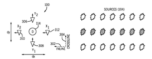
- FIG. 3 To illustrate the inline and crossline directions, an arrangement of a sensor assembly 100 and seismic sources 104 is shown in FIG. 3 .
- the inline direction (x direction) is represented as 302
- the crossline direction (y direction) is represented as 304
- the inline direction (x) and crossline direction (y) are generally perpendicular to each other.
- the sensor assembly 100 has a divergence sensor 114 (to provide output D), y-direction seismic sensors 306 , 308 , and x-direction seismic sensors 310 and 312 .
- a z-direction seismic sensor can also be provided.
- K D ⁇ K S ⁇ U D ⁇ t / ( ⁇ V X ⁇ x + ⁇ V Y ⁇ y ) ( Eq . ⁇ 5 )
- K D K S U D /( p X V X +p Y V Y ) (Eq. 6)
- V X and V Y are considered to be velocity fields. If seismic sensors measure acceleration, the U D data should first be time differentiated. If seismic sensors measure displacement, the U D data should first be time integrated. In these cases, the K D K S term can eventually be computed as a scalar coefficient. Otherwise, the K D K S term may be a complex operator which also includes the time integration or the time differentiation effect (this can be attributed to the difference in term of impulse responses between the divergence and the seismic sensors). In the ensuing discussion, it is assumed that V X and V Y are velocity fields. In alternative implementations, the K D K S term can be computed based on the reciprocal of the right hand-side of Eqs. 5 and 6.
- the local K D K S term can be obtained from the ratio between ⁇ U D / ⁇ t over ( ⁇ V X / ⁇ x+ ⁇ V y / ⁇ y), according to Eq. 5, using any part of unaliased common shot gather (CSG) data (in the x-direction for V X (x,t) and in the y-direction for V Y (y,t)).
- CSG common shot gather
- a workflow for a 3D varying of subterranean medium is depicted in FIG. 4 .
- a common shot gather refers to a grouping of traces recorded by corresponding sensor assemblies in response to a single shot (activation of a single seismic source).
- the corresponding CSG data as collected (at 402 ) by the sensor assemblies in response to the shot, in some implementations include U D , V X , and V Y (collected based on outputs of the divergence sensor and the seismic sensors, respectively). Any aliased portion of the CSG data is removed (at 404 ). Aliased events are removed from each of the U D , V X and V Y data.
- the derivatives ⁇ U D / ⁇ t and ( ⁇ V X / ⁇ x+ ⁇ V Y / ⁇ y) are calculated (at 410 and 412 , respective) based on the CSG data with the aliased portion removed.
- the calibration term K D K S is computed (at 414 ) by taking the ratio of ⁇ U D / ⁇ t to ( ⁇ V X / ⁇ x+ ⁇ V Y / ⁇ y) according to Eq. 5.
- the U D time derivation is “optional” in some implementations (not necessary if V i is displacement for example).
- K D may include the derivation operator.
- the workflow of FIG. 4 can be repeated for each of multiple shots.
- the loop over the frequency ( 406 ) can be omitted in some implementations.
- Computing a ratio between data of Eq. 5 in a time-space window can be performed using one of several techniques. For example, one technique involves calculating the ratio for each time sample and then taking the mean value. Alternatively, calculating the ratio can be done using cross-correlation and auto-correlation between the data. Another technique is based on principal component analysis of a covariant matrix built from cross-correlated and auto-correlated analytic signal data. The foregoing techniques enable calculation of a frequency independent ratio (a scalar number). Alternatively, the ratio can be obtained as a function of frequency (operator of several point length in the time domain), such as by using a Wiener-Levinson technique for example. Using this procedure, any shot (a single activation of a seismic source, whatever its location) can be used to determine K D K S values over the whole receiver (sensor assembly) distribution by computing the trace-by-trace ratios in the CSG domain.
- Removing the aliased part ( 404 in FIG. 4 ) can be accomplished using any one of various techniques.
- a simple technique can include applying a low-pass filter on data to select only frequencies below a predefined maximum frequency.
- an F-K filter can be applied to extract the entire unaliased area, which allows selection of data with relatively low frequencies.
- a technique for removing an aliased portion from the CSG data can mute slow events (typically ground-roll noise), such that the minimum apparent velocity in the CSG data is larger, so that higher frequencies can be used.
- Yet another technique includes applying interpolation to reduce the spatial sampling, such that higher frequency content can be used.
- a common receiver gather (CRG) technique is used instead of the CSG technique of FIG. 4 .
- CSG common receiver gather
- a common receiver gather (CRG) refers to the seismic data acquired by a particular receiver (sensor assembly) for multiple shots (activations of multiple seismic sources).
- FIG. 5 depicts the collection (at 502 ) of U D CRG data for a sensor assembly at position x, y. Moreover, FIG. 5 depicts the collection (at 504 ) of V X CRG data at a sensor assembly at position x ⁇ x/2, y, and the collection (at 506 ) of V X CRG data at position x+ ⁇ x/2, y. Moreover, the FIG. 5 workflow collects (at 508 ) V Y CRG data at position x, y ⁇ y/2, and collects (at 510 ) V Y CRG data at position x, y+ ⁇ y/2.
- the spatial derivative ⁇ V X / ⁇ x is calculated (at 512 ).
- the spatial derivative ⁇ V Y / ⁇ y is calculated (at 514 ).
- the optional time derivative ⁇ U D / ⁇ t is computed (at 516 ) from the U D CRG data collected at 502 , while ( ⁇ V X / ⁇ x+ ⁇ V Y / ⁇ y) is computed (at 518 ) from the spatial derivatives calculated at 512 , 514 .
- the calibration term K D K S is calculated (at 520 ) according to the Eq. 5.
- the FIG. 5 workflow is repeated for all sensor assemblies 100 in the distribution.
- the CRG data can eventually be trace-by-trace scaled-normalized (with the same scaling applied on both ⁇ U D / ⁇ t and ( ⁇ V X / ⁇ x+ ⁇ V y / ⁇ y) in order to prevent the ratio from being predominantly estimated from the strongest amplitude shots (short offset data, i.e., data collected by sensor assemblies close to respective seismic sources).
- the K D K S term is calculated based on the ratio of ⁇ U D / ⁇ t to either ⁇ V X / ⁇ x or ⁇ V Y / ⁇ y—in other words, only inline or crossline seismic data is used. If the K D K S term is calculated based on the ratio of ⁇ U D / ⁇ t to ⁇ V X / ⁇ x (where V X is the inline velocity field), then the computation focuses on the unaliased part of V X , after removal of events that are scattered off the xz plane from both the divergence data U D and inline velocity field V.
- the xz plane includes the x (inline) direction and the generally vertical (z) direction.
- the K D K S term is calculated based on the ratio of ⁇ U D / ⁇ t to ⁇ V Y / ⁇ y (where V Y is the crossline velocity field)
- the computation focuses on the unaliased part of V y , after removal of events that are scattered off the yz plane from both the divergence data U D and crossline velocity field V Y .
- the yz plane includes the y (crossline) direction and the generally vertical (z) direction.
- the techniques discussed according to FIGS. 4 and 5 assume a 3D varying subterranean medium.
- the subterranean medium has varying characteristics in two dimensions (2D varying subterranean medium), namely the x and z dimensions.
- the subterranean medium can be assumed to be invariant in the y dimension.
- the technique of FIG. 4 can be simplified (by using trace-by-trace ratio in CSGs) or the technique of FIG. 5 can be simplified (by using global ratio between CRGs).
- the simplified techniques are able to derive the calibration term K D K S using only inline shots (along the x-direction).
- FIG. 4 technique is simplified by using trace-by-trace ratio in CSGs or the FIG. 5 technique is simplified by using global ratio between CRGs.
- the calibration K D K S term can be derived using only crossline shots (along the y-direction). In this case, the contribution of ⁇ V X / ⁇ x according to Eq. 5 can be neglected and the K D K S value(s) can be obtained from the ⁇ U D / ⁇ t over ⁇ V Y / ⁇ y ratio directly.
- the advantage here is that the relatively dense x-sampling criteria is not required.
- the above described techniques can be applied to the entire recording length of the sensor assembly array, without any specific event selection (except in terms of aliasing in the common-shot domain and eventually offline scattered events for the simplified techniques for 2D varying medium).
- the processed part of the data can contain several P waves, several S waves, as well as ground-roll events (overlapping or not, all with different amplitudes, velocities and emergent angles).
- the quantity p x V X and p y V Y can be automatically determined for example by mapping the seismic data (V X and V Y , CSGs) in the tau-p domain (where tau is intercept time, and p is horizontal slowness), then multiplying the transformed data by the known p x and p y values (respectively, in the slowness domain) and then transforming back the data in the conventional time-offset domain.
- the K D K S term is obtained by computing the ratio of Eq. 6.
- one of the first and second products can be disregarded to simplify computing the calibration term.
- the p y V Y product is set to zero for pure inline events (typically for inline shots)
- the p x V X product is set to zero for pure crossline events (typically for crossline shots).
- this process allows the determination of the calibration term distribution (at each receiver location) using a single shot, but the process can be repeated for several shots (potentially all) to better constrain the results.
- the ratio of Eq. 6 can be determined in the common-receiver domain as explained in the text accompanying FIG. 5 above, while the p i V i components are computed by forward-inverse tau-p transform of the corresponding CSGs.
- the investigated seismic wave can be any of a P wave, an S wave or a Rayleigh wave, but they have to be pure events (i.e. events that do not overlap with other waves) such that the corresponding horizontal slownesses (p x and p y ) can be measured.
- array(s) of sensor assemblies are also used to estimate the slownesses at each sensor assembly position, but the non-aliasing criteria can be relaxed (at least for non-dispersive events).
- the K D K S term can be evaluated from the ratio between co-located divergence data and horizontal seismic data for any kind of waves of known horizontal slownesses (p x , p y )—slownesses of pure events. Once the horizontal slownesses are measured, the K D K S term at a given sensor assembly location is obtained by calculating the local U D /(p x V X +p y V Y ) ratio, according to Eq. 6, in the corresponding time-window.
- the workflow according to some implementations for the foregoing technique is depicted in FIG. 6 .
- CSG data including U D , V X , and V Y
- CSG data are collected (at 602 ).
- the horizontal slownesses, p x , p y are measured (at 610 ).
- the K D K S term is calculated according to Eq. 6 (at 612 ).
- a simplified version of the FIG. 6 workflow can be used in the case of 2D varying subterranean medium (y-invariant medium, or a representation of the medium after removal of crossline propagating events).
- a first simplified technique uses inline shots only along the x-direction.
- K D K S U D /(p y V Y ).
- FIG. 6 technique or simplified versions thereof are applied in the common-shot domain in order to measure the slowness(es) at the receiver side.
- various pure events typically the first break or the ground-roll
- K D K S can potentially be used to estimate K D K S at the receiver locations in each CSG. Therefore, an inversion procedure (least square for example) may be implemented to integrate all the results obtained from several events in several shot gathers but at a given receiver location.
- a system of linear equations may be solved (as a least squares problem for example).
- a pre-processing step (like F-K filtering for example) may be performed in order to separate events prior to further processing to calculate the K D K S term.
- the K D K S term can be estimated in the tau-p x -p y domain, from the ratio U D (tau, p x , p y ) over (p x V X (tau, p x , p y )+p y V Y (tau, p x , p y )), taking into account all the shots (if processing in common-receiver domain), or equivalently all the sensor assemblies (if processing in the common-shot domain).
- tau represents intercept time.
- the K D K S term at the sensor assembly positions is given by the U D (tau, p x ) over p x V X (tau, p x ) ratio, if only inline events are used.
- the K D K S value at the sensor assembly position(s) is given by the U D (tau, p x ) over p y V Y (tau, p x ) ratio, if only crossline events are used.
- the ratio can be obtained without any slowness measurement or time windowing (but it is better to focus on tau-p x -p y windows with relatively good signal-to-noise ratio, typically at large slownesses). Note that a similar procedure can be derived in the F-K domain.
- Eq. 9 shows that the angular frequency ( ⁇ ) derivative of the ratio of the pressure and displacement is equal to K D K S divided by the group velocity (c g ) of the Rayleigh wave.
- the group velocity of a wave is the velocity with which the overall shape of the wave's amplitudes—known as the modulation or envelope of the wave—propagates through space.
- the group velocity (c g ) may be obtained by a technique that uses only a single receiver, such as the Frequency Time Analysis (FTAN) technique (which is insensitive to aliasing).
- FTAN Frequency Time Analysis
- the group velocity (c g ) determined this way is the average group-velocity between source and receiver.
- An extension of this technique can include group-velocity measurement made between various sources and receivers resulting in a 2D map of the local group velocities to provide a 2D model of K D K S term, without the need to satisfy a sampling or aliasing criterion.
- K D K S term may be solved in a frequency dependent or frequency independent manner.
- K D K S may be solved in a frequency independent manner (solve for a scalar), or frequency dependent manner (solve for an operator, several point length in time).
- the calibration term K D is already known, then it is possible to estimate the near-surface property term K S at each receiver location, eventually as a function of pseudo-depth if the process is applied for each frequency independently.
- Near-surface properties are particularly useful for noise characterization, shallow drilling hazard detection, depth imaging, P-S wavefield separation, static corrections, and so forth.
- the calibration term K D is unknown but is assumed to be constant for each sensor assembly (i.e. constant calibration and constant coupling along the sensor assembly distribution), it is possible to estimate the lateral variations ⁇ K S along the receiver distribution, eventually as a function of pseudo-depth if the process is applied for each frequency. Lateral variations of the near-surface properties are particularly useful for noise characterization, shallow drilling hazard, depth imaging, static corrections, and so forth.
- the near-surface property term K S may be already known using various techniques to previously determine ⁇ , ⁇ and ⁇ , (parameters discussed above in connection with Eq. 2). Examples of such techniques include tomography inversion for ⁇ , P-wave polarization analysis or ground-roll phase velocity inversion for ⁇ , empirical relations techniques, or others.
- K S is known, if a K D K S frequency dependent solution has been obtained, one can obtain an estimate for the operator K D . Assume that K S is a scalar (not dependent on frequency), it is possible to derive the spectral shape of K D (f).
- a processor can include a microprocessor, microcontroller, processor module or subsystem, programmable integrated circuit, programmable gate array, or another control or computing device.
- a “processor” can refer to a single component or to plural components (e.g., one CPU or multiple CPUs).
- Data and instructions are stored in respective storage devices, which are implemented as one or more computer-readable or machine-readable storage media.
- the storage media include different forms of memory including semiconductor memory devices such as dynamic or static random access memories (DRAMs or SRAMs), erasable and programmable read-only memories (EPROMs), electrically erasable and programmable read-only memories (EEPROMs) and flash memories; magnetic disks such as fixed, floppy and removable disks; other magnetic media including tape; optical media such as compact disks (CDs) or digital video disks (DVDs); or other types of storage devices.
- DRAMs or SRAMs dynamic or static random access memories
- EPROMs erasable and programmable read-only memories
- EEPROMs electrically erasable and programmable read-only memories
- flash memories such as fixed, floppy and removable disks
- magnetic media such as fixed, floppy and removable disks
- optical media such as compact disks (CDs) or digital video disks (DVDs); or other
- instructions discussed above can be provided on one computer-readable or machine-readable storage medium, or alternatively, can be provided on multiple computer-readable or machine-readable storage media distributed in a large system having possibly plural nodes.
- Such computer-readable or machine-readable storage medium or media is (are) considered to be part of an article (or article of manufacture).
- An article or article of manufacture can refer to any manufactured single component or multiple components.
Landscapes
- Engineering & Computer Science (AREA)
- Remote Sensing (AREA)
- Physics & Mathematics (AREA)
- Life Sciences & Earth Sciences (AREA)
- Acoustics & Sound (AREA)
- Environmental & Geological Engineering (AREA)
- Geology (AREA)
- General Life Sciences & Earth Sciences (AREA)
- General Physics & Mathematics (AREA)
- Geophysics (AREA)
- Geophysics And Detection Of Objects (AREA)
Abstract
Description
U p =K∇U, (Eq. 1)
where U is a total wavefield in terms of displacement, and K is the bulk modulus (unit Pascal) of the medium that depends on the medium properties.
where VX and VY are the velocity fields in the inline and crossline directions, and pX and pY are the inline and crossline horizontal slownesses (inverse of the apparent velocities, or equivalently the slope of an event in the time-space domain). The inline and crossline directions are discussed in connection with
where KS depends on a characteristic of the near-surface subterranean medium, and where KD (no unit) depends on the sensitivity of the sensor assembly (e.g., KD converts the pressure fluctuations outside the container into the pressure fluctuations inside the container and compensate for the fact that the divergence sensor and the seismic sensor may have different impulse responses).
K D K S =U D/(p X V X +p Y V Y) (Eq. 6)
where kR is the phase-velocity of the Rayleigh wave. After taking the derivative with respect to frequency, the following is obtained:
Claims (25)
Priority Applications (2)
| Application Number | Priority Date | Filing Date | Title |
|---|---|---|---|
| US12/939,331 US9091783B2 (en) | 2010-11-04 | 2010-11-04 | Computing a calibration term based on combining divergence data and seismic data |
| PCT/US2011/057670 WO2012061125A2 (en) | 2010-11-04 | 2011-10-25 | Computing a calibration term based on combining divergence data and seismic data |
Applications Claiming Priority (1)
| Application Number | Priority Date | Filing Date | Title |
|---|---|---|---|
| US12/939,331 US9091783B2 (en) | 2010-11-04 | 2010-11-04 | Computing a calibration term based on combining divergence data and seismic data |
Publications (2)
| Publication Number | Publication Date |
|---|---|
| US20120113749A1 US20120113749A1 (en) | 2012-05-10 |
| US9091783B2 true US9091783B2 (en) | 2015-07-28 |
Family
ID=46019520
Family Applications (1)
| Application Number | Title | Priority Date | Filing Date |
|---|---|---|---|
| US12/939,331 Active 2033-06-25 US9091783B2 (en) | 2010-11-04 | 2010-11-04 | Computing a calibration term based on combining divergence data and seismic data |
Country Status (2)
| Country | Link |
|---|---|
| US (1) | US9091783B2 (en) |
| WO (1) | WO2012061125A2 (en) |
Cited By (2)
| Publication number | Priority date | Publication date | Assignee | Title |
|---|---|---|---|---|
| US20220406988A1 (en) * | 2017-12-15 | 2022-12-22 | Pgs Geophysical As | Seismic Pressure and Acceleration Measurement |
| US12498499B2 (en) | 2018-06-08 | 2025-12-16 | Pgs Geophysical As | Linear array of piezoelectric transducers for towed marine streamers |
Families Citing this family (8)
| Publication number | Priority date | Publication date | Assignee | Title |
|---|---|---|---|---|
| GB2456313B (en) * | 2008-01-10 | 2010-05-12 | Westerngeco Seismic Holdings | Sensor devices |
| US9304221B2 (en) | 2011-04-04 | 2016-04-05 | Westerngeco L.L.C. | Determining an indication of wavefield velocity |
| US9753167B2 (en) | 2012-07-23 | 2017-09-05 | Westerngeco L.L.C. | Calibrating rotation data and translational data |
| US20140200816A1 (en) * | 2013-01-14 | 2014-07-17 | Westerngeco L.L.C. | Seismic data processing |
| US10048395B2 (en) | 2013-02-01 | 2018-08-14 | Westerngeco L.L.C. | Computing a gradient based on differences of plural pairs of particle motion sensors |
| US10620330B2 (en) | 2013-03-19 | 2020-04-14 | Westerngeco L.L.C. | Estimating translational data |
| US10408954B2 (en) | 2014-01-17 | 2019-09-10 | Westerngeco L.L.C. | Seismic sensor coupling |
| WO2017100690A1 (en) * | 2015-12-11 | 2017-06-15 | Seismos Inc. | Continuous subsurface fluid surveillance method |
Citations (39)
| Publication number | Priority date | Publication date | Assignee | Title |
|---|---|---|---|---|
| GB1256304A (en) | 1968-02-14 | 1971-12-08 | Inst Francais Du Petrole | Device for seismic prospecting on land |
| US3722751A (en) | 1970-10-01 | 1973-03-27 | North American Rockwell | Control fold liquid expulsion bladder |
| US3934218A (en) | 1971-08-17 | 1976-01-20 | Seiscom Delta Inc. | Apparatus and method for seismic exploration |
| US4134097A (en) | 1977-06-13 | 1979-01-09 | Shell Oil Company | Combination geophone-hydrophone |
| US4163206A (en) | 1976-04-22 | 1979-07-31 | Western Geophysical Co. Of America | Apparatus and method for seismic wave detection |
| US4334296A (en) | 1978-03-16 | 1982-06-08 | Western Geophysical Co. Of America | Seismic method and apparatus |
| US4599713A (en) | 1983-03-30 | 1986-07-08 | Compagnie General De Geophysique | Seismic detector |
| US4890264A (en) | 1988-03-21 | 1989-12-26 | Atlantic Richfield Company | Seismic exploration method and apparatus for cancelling non-uniformly distributed noise |
| US4937794A (en) * | 1985-05-06 | 1990-06-26 | Western Atlas International, Inc. | Seismic noise suppression method |
| US4979150A (en) | 1989-08-25 | 1990-12-18 | Halliburton Geophysical Services, Inc. | System for attenuation of water-column reverberations |
| US4996675A (en) | 1988-12-23 | 1991-02-26 | Institut Francais Du Petrole | Signal sensor insensitive to static pressure variations |
| US5189644A (en) * | 1992-02-04 | 1993-02-23 | Wood Lawrence C | Removal of amplitude aliasing effect from seismic data |
| US5235554A (en) * | 1991-03-11 | 1993-08-10 | Halliburton Geophysical Services, Inc. | Method for correcting impulse response differences of hydrophones and geophones as well as geophone coupling to the water-bottom in dual-sensor, bottom-cable seismic operations |
| US5555530A (en) | 1992-12-12 | 1996-09-10 | Schlumberger Technology Corporation | Method for improving signal to noise ratio |
| EP0736781A1 (en) | 1995-04-03 | 1996-10-09 | Compagnie Generale De Geophysique | Low frequency seismic sensor |
| FR2738642A1 (en) | 1995-09-12 | 1997-03-14 | Thomson Csf | Seismic sensor for detecting land vehicle or helicopter movement |
| US5621699A (en) * | 1995-07-07 | 1997-04-15 | Pgs Ocean Bottom Seismic, Inc. | Apparatus and method of calibrating vertical particle velocity detector and pressure detector in a sea-floor cable with in-situ passive monitoring |
| US5648938A (en) | 1993-10-06 | 1997-07-15 | Ensign Geophysics Limited | Seismic data acquisition |
| US5774417A (en) | 1996-10-25 | 1998-06-30 | Atlantic Richfield Company | Amplitude and phase compensation in dual-sensor ocean bottom cable seismic data processing |
| US6381544B1 (en) | 2000-07-19 | 2002-04-30 | Westerngeco, L.L.C. | Deterministic cancellation of air-coupled noise produced by surface seimic sources |
| US6442304B1 (en) | 1998-12-17 | 2002-08-27 | Chevron U.S.A. Inc. | Apparatus and method for protecting devices, especially fibre optic devices, in hostile environments |
| US6446009B1 (en) | 1998-06-27 | 2002-09-03 | Schlumberger Technology Corporation | Seismic data acquisition and method for spatially filtering seismic data |
| US6584038B2 (en) * | 2000-02-14 | 2003-06-24 | Institut Francais Du Petrole | Device for receiving seismic waves and method for coupling them with a solid environment |
| US6903999B2 (en) | 2000-01-21 | 2005-06-07 | Schlumberger Technology Corporation | System and method for estimating seismic material properties |
| US6932185B2 (en) | 2002-08-22 | 2005-08-23 | Institut Francais Du Petrole | Acquisition method and device for seismic exploration of a geologic formation by permanent receivers set on the sea bottom |
| US6961283B2 (en) | 2002-03-20 | 2005-11-01 | Input/Output, Inc. | Adaptive filtering apparatus and method for seismic data acquisition |
| GB2414299A (en) | 2004-05-21 | 2005-11-23 | Westerngeco Ltd | Interpolation and/or extrapolation of multi-component seismic streamer recordings |
| US7082079B2 (en) | 2003-03-20 | 2006-07-25 | Weatherford/Lamb, Inc. | Pressure compensated hydrophone |
| US7142481B1 (en) | 2005-09-12 | 2006-11-28 | Pgs Geophysical As | Method and system for making marine seismic streamers |
| US7359283B2 (en) | 2004-03-03 | 2008-04-15 | Pgs Americas, Inc. | System for combining signals of pressure sensors and particle motion sensors in marine seismic streamers |
| US20080221801A1 (en) | 2007-03-09 | 2008-09-11 | Craft Kenneth L | Geophone noise attenuation and wavefield separation using a multi-dimensional decomposition technique |
| US7551517B2 (en) | 2006-05-05 | 2009-06-23 | Optoplan As | Seabed seismic station packaging |
| GB2456313A (en) * | 2008-01-10 | 2009-07-15 | Westerngeco Seismic Holdings | Fluid filled seismic sensor for installation at land-air interface |
| WO2010082131A2 (en) | 2009-01-19 | 2010-07-22 | Geco Technology B.V. | Processing seismic data |
| US20110080808A1 (en) | 2009-10-05 | 2011-04-07 | Everhard Muyzert | Sensor assembly having a seismic sensor and a divergence sensor |
| US20110082647A1 (en) | 2009-10-05 | 2011-04-07 | Pascal Edme | Combining seismic data from sensors to attenuate noise |
| US20110085417A1 (en) | 2009-10-12 | 2011-04-14 | Daniel Ronnow | String of Sensor Assemblies Having a Seismic Sensor and Pressure Sensor |
| US20110249530A1 (en) | 2010-04-09 | 2011-10-13 | Qinglin Liu | Arranging sensor assemblies for seismic surveying |
| US8520469B2 (en) | 2009-10-12 | 2013-08-27 | Westerngeco L.L.C. | Sensor assembly having a seismic sensor, pressure sensor, and processor to apply first and second digital filters |
-
2010
- 2010-11-04 US US12/939,331 patent/US9091783B2/en active Active
-
2011
- 2011-10-25 WO PCT/US2011/057670 patent/WO2012061125A2/en not_active Ceased
Patent Citations (43)
| Publication number | Priority date | Publication date | Assignee | Title |
|---|---|---|---|---|
| GB1256304A (en) | 1968-02-14 | 1971-12-08 | Inst Francais Du Petrole | Device for seismic prospecting on land |
| US3722751A (en) | 1970-10-01 | 1973-03-27 | North American Rockwell | Control fold liquid expulsion bladder |
| US3934218A (en) | 1971-08-17 | 1976-01-20 | Seiscom Delta Inc. | Apparatus and method for seismic exploration |
| US4163206A (en) | 1976-04-22 | 1979-07-31 | Western Geophysical Co. Of America | Apparatus and method for seismic wave detection |
| US4134097A (en) | 1977-06-13 | 1979-01-09 | Shell Oil Company | Combination geophone-hydrophone |
| US4334296A (en) | 1978-03-16 | 1982-06-08 | Western Geophysical Co. Of America | Seismic method and apparatus |
| US4599713A (en) | 1983-03-30 | 1986-07-08 | Compagnie General De Geophysique | Seismic detector |
| US4937794A (en) * | 1985-05-06 | 1990-06-26 | Western Atlas International, Inc. | Seismic noise suppression method |
| US4890264A (en) | 1988-03-21 | 1989-12-26 | Atlantic Richfield Company | Seismic exploration method and apparatus for cancelling non-uniformly distributed noise |
| US4996675A (en) | 1988-12-23 | 1991-02-26 | Institut Francais Du Petrole | Signal sensor insensitive to static pressure variations |
| US4979150A (en) | 1989-08-25 | 1990-12-18 | Halliburton Geophysical Services, Inc. | System for attenuation of water-column reverberations |
| US5235554A (en) * | 1991-03-11 | 1993-08-10 | Halliburton Geophysical Services, Inc. | Method for correcting impulse response differences of hydrophones and geophones as well as geophone coupling to the water-bottom in dual-sensor, bottom-cable seismic operations |
| US5189644A (en) * | 1992-02-04 | 1993-02-23 | Wood Lawrence C | Removal of amplitude aliasing effect from seismic data |
| US5555530A (en) | 1992-12-12 | 1996-09-10 | Schlumberger Technology Corporation | Method for improving signal to noise ratio |
| US5648938A (en) | 1993-10-06 | 1997-07-15 | Ensign Geophysics Limited | Seismic data acquisition |
| EP0736781A1 (en) | 1995-04-03 | 1996-10-09 | Compagnie Generale De Geophysique | Low frequency seismic sensor |
| US5621699A (en) * | 1995-07-07 | 1997-04-15 | Pgs Ocean Bottom Seismic, Inc. | Apparatus and method of calibrating vertical particle velocity detector and pressure detector in a sea-floor cable with in-situ passive monitoring |
| FR2738642A1 (en) | 1995-09-12 | 1997-03-14 | Thomson Csf | Seismic sensor for detecting land vehicle or helicopter movement |
| US5774417A (en) | 1996-10-25 | 1998-06-30 | Atlantic Richfield Company | Amplitude and phase compensation in dual-sensor ocean bottom cable seismic data processing |
| US6446009B1 (en) | 1998-06-27 | 2002-09-03 | Schlumberger Technology Corporation | Seismic data acquisition and method for spatially filtering seismic data |
| US6442304B1 (en) | 1998-12-17 | 2002-08-27 | Chevron U.S.A. Inc. | Apparatus and method for protecting devices, especially fibre optic devices, in hostile environments |
| US6903999B2 (en) | 2000-01-21 | 2005-06-07 | Schlumberger Technology Corporation | System and method for estimating seismic material properties |
| US6584038B2 (en) * | 2000-02-14 | 2003-06-24 | Institut Francais Du Petrole | Device for receiving seismic waves and method for coupling them with a solid environment |
| US6381544B1 (en) | 2000-07-19 | 2002-04-30 | Westerngeco, L.L.C. | Deterministic cancellation of air-coupled noise produced by surface seimic sources |
| US6961283B2 (en) | 2002-03-20 | 2005-11-01 | Input/Output, Inc. | Adaptive filtering apparatus and method for seismic data acquisition |
| US6932185B2 (en) | 2002-08-22 | 2005-08-23 | Institut Francais Du Petrole | Acquisition method and device for seismic exploration of a geologic formation by permanent receivers set on the sea bottom |
| US7082079B2 (en) | 2003-03-20 | 2006-07-25 | Weatherford/Lamb, Inc. | Pressure compensated hydrophone |
| US7359283B2 (en) | 2004-03-03 | 2008-04-15 | Pgs Americas, Inc. | System for combining signals of pressure sensors and particle motion sensors in marine seismic streamers |
| GB2414299A (en) | 2004-05-21 | 2005-11-23 | Westerngeco Ltd | Interpolation and/or extrapolation of multi-component seismic streamer recordings |
| US8396668B2 (en) | 2004-05-21 | 2013-03-12 | Westerngeco L.L.C. | Marine seismic surveying employing interpolated multicomponent streamer pressure data |
| US7142481B1 (en) | 2005-09-12 | 2006-11-28 | Pgs Geophysical As | Method and system for making marine seismic streamers |
| US7551517B2 (en) | 2006-05-05 | 2009-06-23 | Optoplan As | Seabed seismic station packaging |
| US20080221801A1 (en) | 2007-03-09 | 2008-09-11 | Craft Kenneth L | Geophone noise attenuation and wavefield separation using a multi-dimensional decomposition technique |
| GB2456313A (en) * | 2008-01-10 | 2009-07-15 | Westerngeco Seismic Holdings | Fluid filled seismic sensor for installation at land-air interface |
| US8665671B2 (en) | 2008-01-10 | 2014-03-04 | Westerngeco L.L.C. | Seismic sensor devices |
| WO2010082131A2 (en) | 2009-01-19 | 2010-07-22 | Geco Technology B.V. | Processing seismic data |
| US20120035852A1 (en) | 2009-01-19 | 2012-02-09 | Schlumberger Technology Corporation | Processing seismic data |
| US20110080808A1 (en) | 2009-10-05 | 2011-04-07 | Everhard Muyzert | Sensor assembly having a seismic sensor and a divergence sensor |
| US20110082647A1 (en) | 2009-10-05 | 2011-04-07 | Pascal Edme | Combining seismic data from sensors to attenuate noise |
| US8712694B2 (en) | 2009-10-05 | 2014-04-29 | Westerngeco L.L.C. | Combining seismic data from sensors to attenuate noise |
| US20110085417A1 (en) | 2009-10-12 | 2011-04-14 | Daniel Ronnow | String of Sensor Assemblies Having a Seismic Sensor and Pressure Sensor |
| US8520469B2 (en) | 2009-10-12 | 2013-08-27 | Westerngeco L.L.C. | Sensor assembly having a seismic sensor, pressure sensor, and processor to apply first and second digital filters |
| US20110249530A1 (en) | 2010-04-09 | 2011-10-13 | Qinglin Liu | Arranging sensor assemblies for seismic surveying |
Non-Patent Citations (6)
| Title |
|---|
| Dey et al., "Noise suppression on Geophone data using microphone measurements", CREWES, Research Report vol. 12 (2000) http://www.crewes.org/ForOurSponsors/ResearchReports/2000/2000-08.pdf. |
| Edme, et al., Near-Surface S-wave velocity estimation from P-wave polarization analysis, SEG Houston 2009 International Exposition and Annual Meeting, pp. 4289-4293. |
| Edme, et al., Receiver Function Decomposition of OBC Data : Theory, Geophysical Journal International, 2009, pp. 966-977, vol. 177. |
| Greensted, "The Lab Book Pages: Delay Sum Beamforming", Oct. 2012, The Lab Book Pages, pp. 1-9, http://www.labbookpages.co.uk/audio/beamforming/delaySum.html. |
| International Search Report of PCT Application No. PCT/US2011/057670 dated May 4, 2012. |
| Soubaras, Ocean Bottom Hydrophone and Geophone Processing, SEG Expanded Abstracts, 1996, pp. 24-27 vol. 15. |
Cited By (4)
| Publication number | Priority date | Publication date | Assignee | Title |
|---|---|---|---|---|
| US20220406988A1 (en) * | 2017-12-15 | 2022-12-22 | Pgs Geophysical As | Seismic Pressure and Acceleration Measurement |
| US11871675B2 (en) * | 2017-12-15 | 2024-01-09 | Pgs Geophysical As | Seismic pressure and acceleration measurement |
| US11889760B2 (en) | 2017-12-15 | 2024-01-30 | Pgs Geophysical As | Seismic pressure and acceleration sensor |
| US12498499B2 (en) | 2018-06-08 | 2025-12-16 | Pgs Geophysical As | Linear array of piezoelectric transducers for towed marine streamers |
Also Published As
| Publication number | Publication date |
|---|---|
| WO2012061125A2 (en) | 2012-05-10 |
| WO2012061125A3 (en) | 2012-07-26 |
| US20120113749A1 (en) | 2012-05-10 |
Similar Documents
| Publication | Publication Date | Title |
|---|---|---|
| US9091783B2 (en) | Computing a calibration term based on combining divergence data and seismic data | |
| US8712694B2 (en) | Combining seismic data from sensors to attenuate noise | |
| CN103582827B (en) | Use the noise attentuation of spin data | |
| US10078146B2 (en) | Seismic acquisition system and technique | |
| CN103959099B (en) | Use the wave field separation of gradient sensor | |
| US9304221B2 (en) | Determining an indication of wavefield velocity | |
| US9753167B2 (en) | Calibrating rotation data and translational data | |
| US10620330B2 (en) | Estimating translational data | |
| US20160047927A1 (en) | Determination of an impulse response at a subsurface image level |
Legal Events
| Date | Code | Title | Description |
|---|---|---|---|
| AS | Assignment |
Owner name: WESTERNGECO LLC, TEXAS Free format text: ASSIGNMENT OF ASSIGNORS INTEREST;ASSIGNORS:EDME, PASCAL;MUYZERT, EVERHARD;REEL/FRAME:025347/0906 Effective date: 20100416 |
|
| STCF | Information on status: patent grant |
Free format text: PATENTED CASE |
|
| MAFP | Maintenance fee payment |
Free format text: PAYMENT OF MAINTENANCE FEE, 4TH YEAR, LARGE ENTITY (ORIGINAL EVENT CODE: M1551); ENTITY STATUS OF PATENT OWNER: LARGE ENTITY Year of fee payment: 4 |
|
| MAFP | Maintenance fee payment |
Free format text: PAYMENT OF MAINTENANCE FEE, 8TH YEAR, LARGE ENTITY (ORIGINAL EVENT CODE: M1552); ENTITY STATUS OF PATENT OWNER: LARGE ENTITY Year of fee payment: 8 |