US9081260B2 - Dome camera - Google Patents
Dome camera Download PDFInfo
- Publication number
- US9081260B2 US9081260B2 US14/337,355 US201414337355A US9081260B2 US 9081260 B2 US9081260 B2 US 9081260B2 US 201414337355 A US201414337355 A US 201414337355A US 9081260 B2 US9081260 B2 US 9081260B2
- Authority
- US
- United States
- Prior art keywords
- camera lens
- camera
- dome
- filter
- tilt angle
- Prior art date
- Legal status (The legal status is an assumption and is not a legal conclusion. Google has not performed a legal analysis and makes no representation as to the accuracy of the status listed.)
- Active
Links
Images


Classifications
-
- G—PHYSICS
- G03—PHOTOGRAPHY; CINEMATOGRAPHY; ANALOGOUS TECHNIQUES USING WAVES OTHER THAN OPTICAL WAVES; ELECTROGRAPHY; HOLOGRAPHY
- G03B—APPARATUS OR ARRANGEMENTS FOR TAKING PHOTOGRAPHS OR FOR PROJECTING OR VIEWING THEM; APPARATUS OR ARRANGEMENTS EMPLOYING ANALOGOUS TECHNIQUES USING WAVES OTHER THAN OPTICAL WAVES; ACCESSORIES THEREFOR
- G03B11/00—Filters or other obturators specially adapted for photographic purposes
- G03B11/04—Hoods or caps for eliminating unwanted light from lenses, viewfinders or focusing aids
- G03B11/045—Lens hoods or shields
-
- G—PHYSICS
- G03—PHOTOGRAPHY; CINEMATOGRAPHY; ANALOGOUS TECHNIQUES USING WAVES OTHER THAN OPTICAL WAVES; ELECTROGRAPHY; HOLOGRAPHY
- G03B—APPARATUS OR ARRANGEMENTS FOR TAKING PHOTOGRAPHS OR FOR PROJECTING OR VIEWING THEM; APPARATUS OR ARRANGEMENTS EMPLOYING ANALOGOUS TECHNIQUES USING WAVES OTHER THAN OPTICAL WAVES; ACCESSORIES THEREFOR
- G03B11/00—Filters or other obturators specially adapted for photographic purposes
- G03B11/04—Hoods or caps for eliminating unwanted light from lenses, viewfinders or focusing aids
- G03B11/043—Protective lens closures or lens caps built into cameras
-
- G—PHYSICS
- G03—PHOTOGRAPHY; CINEMATOGRAPHY; ANALOGOUS TECHNIQUES USING WAVES OTHER THAN OPTICAL WAVES; ELECTROGRAPHY; HOLOGRAPHY
- G03B—APPARATUS OR ARRANGEMENTS FOR TAKING PHOTOGRAPHS OR FOR PROJECTING OR VIEWING THEM; APPARATUS OR ARRANGEMENTS EMPLOYING ANALOGOUS TECHNIQUES USING WAVES OTHER THAN OPTICAL WAVES; ACCESSORIES THEREFOR
- G03B17/00—Details of cameras or camera bodies; Accessories therefor
- G03B17/02—Bodies
-
- G—PHYSICS
- G03—PHOTOGRAPHY; CINEMATOGRAPHY; ANALOGOUS TECHNIQUES USING WAVES OTHER THAN OPTICAL WAVES; ELECTROGRAPHY; HOLOGRAPHY
- G03B—APPARATUS OR ARRANGEMENTS FOR TAKING PHOTOGRAPHS OR FOR PROJECTING OR VIEWING THEM; APPARATUS OR ARRANGEMENTS EMPLOYING ANALOGOUS TECHNIQUES USING WAVES OTHER THAN OPTICAL WAVES; ACCESSORIES THEREFOR
- G03B17/00—Details of cameras or camera bodies; Accessories therefor
- G03B17/56—Accessories
- G03B17/561—Support related camera accessories
-
- G—PHYSICS
- G08—SIGNALLING
- G08B—SIGNALLING OR CALLING SYSTEMS; ORDER TELEGRAPHS; ALARM SYSTEMS
- G08B13/00—Burglar, theft or intruder alarms
- G08B13/18—Actuation by interference with heat, light, or radiation of shorter wavelength; Actuation by intruding sources of heat, light, or radiation of shorter wavelength
- G08B13/189—Actuation by interference with heat, light, or radiation of shorter wavelength; Actuation by intruding sources of heat, light, or radiation of shorter wavelength using passive radiation detection systems
- G08B13/194—Actuation by interference with heat, light, or radiation of shorter wavelength; Actuation by intruding sources of heat, light, or radiation of shorter wavelength using passive radiation detection systems using image scanning and comparing systems
- G08B13/196—Actuation by interference with heat, light, or radiation of shorter wavelength; Actuation by intruding sources of heat, light, or radiation of shorter wavelength using passive radiation detection systems using image scanning and comparing systems using television cameras
- G08B13/19617—Surveillance camera constructional details
- G08B13/1963—Arrangements allowing camera rotation to change view, e.g. pivoting camera, pan-tilt and zoom [PTZ]
Definitions
- the present invention relates to a dome camera including a dome cover for covering a camera lens.
- a dome camera is used as a surveillance camera or the like.
- a camera lens is covered by a dome cover, and the camera lens is protected by the dome cover.
- a general surveillance camera includes a pan tilt function (a function of rotating a camera lens in a pan direction and a tilt direction) and a zoom function.
- a conventional dome camera includes a hemispherical dome cover, and the center of rotation of a camera lens is arranged to be on the optical axis and to coincide with the center of the dome cover. It is known that a good image is obtained according to this arrangement.
- the present invention is made in view of the background described above.
- the object of the present invention is to provide a dome camera capable of achieving both securing of a wide field of view and reduction in the image quality deterioration in a case of capturing an image in a direction at a large tilt angle (a direction near the horizontal direction).
- One mode of the present invention is a dome camera, and this dome camera includes a camera lens capable of rotating in a tilt direction, a dome cover for covering the camera lens, and filter insertion means for inserting a polarizing filter or a partially darkening filter on an optical axis of the camera lens as a tilt angle of the camera lens whose tilt rotation axis is positioned more in a zenith direction than a center position of the dome cover becomes larger than a predetermined threshold angle.
- the present invention includes other modes.
- the disclosure of the invention intends to provide some modes of the present invention, and does not intend to limit the scope of the invention described and claimed herein.
- FIG. 1 is an explanatory diagram of a dome camera according to a first embodiment (tilt angle: large).
- FIG. 2 is an explanatory diagram of the dome camera according to the first embodiment (tilt angle: small).
- FIG. 3 is a perspective view of a lens unit according to the first embodiment (polarizing filter: inserted position).
- FIG. 4 is a perspective view of the lens unit according to the first embodiment (polarizing filter: retracted position).
- FIG. 5 is a perspective view of a lens unit according to a modified example of the first embodiment (darkening filter: inserted position).
- FIG. 6 is a diagram of relationships of a tilt angle to the amount of offset and insertion/non-insertion of a filter according to the first embodiment.
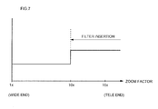
- FIG. 7 is a diagram of a relationship between a zoom factor and insertion/non-insertion of a filter according to the first embodiment.
- FIG. 8 is a diagram of a relationship between a zoom factor and insertion/non-insertion of a filter according to a modified example of the first embodiment.
- FIG. 9 is an explanatory diagram of a filter insertion area according to the first embodiment.
- FIG. 10 is a perspective view of a camera unit according to a second embodiment.
- FIG. 11 is a front view of the camera unit according to the second embodiment (polarizing filter inserted position).
- FIG. 12 is a front view of the camera unit according to the second embodiment (infrared cut filter inserted position).
- FIG. 13 is a front view of the camera unit according to the second embodiment (optical glass inserted position).
- FIG. 14 is a perspective view of a filter switching mechanism according to a modified example of the second embodiment.
- FIG. 15 is a perspective view of the filter switching mechanism according to the modified example of the second embodiment (at a time of polarizing filter insertion).
- a dome camera of the present invention is configured to include a camera lens capable of rotating in a tilt direction, a dome cover for covering the camera lens, and filter insertion means for inserting a polarizing filter or a partially darkening filter on an optical axis of the camera lens as a tilt angle of the camera lens whose tilt rotation axis is positioned more in a zenith direction than a center position of the dome cover becomes larger than a predetermined threshold angle.
- a polarizing filter or a partially darkening filter (a darkening filter by which incident light is partially blocked) is inserted on the optical axis of the camera lens.
- the polarizing filter or the partially darkening filter the image quality may be prevented from deteriorating due to offsetting of the camera lens. Accordingly, securing of a wide field of view and reduction in the image quality deterioration may both be achieved in the case of capturing an image in a direction at a large tilt angle (a direction near the horizontal direction).
- the partially darkening filter may include a blocking area that blocks half of a field of view of the camera lens, and the blocking area may be set across half a range on an opposite side of the zenith direction of the dome cover.
- the camera lens may include a zoom function, and when a zoom factor of the camera lens is within a range of factors on a TELE-end side greater than a predetermined threshold factor, the filter insertion means may insert the polarizing filter or the partially darkening filter on the optical axis of the camera lens.
- the polarizing filter or the partially darkening filter when the zoom factor of the camera lens is set on the TELE-end side, the polarizing filter or the partially darkening filter is inserted on the optical axis of the camera lens, and the image quality may be prevented, by the polarizing filter or the partially darkening filter, from deteriorating due to the offset of the camera lens. Additionally, when the zoom factor of the camera lens is set on a WIDE-end side, the image quality is not so deteriorated, and in this case, the polarizing filter or the partially darkening filter does not have to be inserted regardless of the tilt angle of the camera lens.
- the polarizing filter or the partially darkening filter may be inserted in front of the camera lens.
- the polarizing filter or the partially darkening filter is inserted in front of the camera lens, and light before entering the camera lens is polarized by the polarizing lens or is partially blocked by the partially darkening filter. That is, light which has been polarized by the polarizing lens or light which has been partially blocked by the partially darkening filter enters the camera lens. Deterioration of the image quality due to the offset of the camera lens may thereby be suppressed.
- the polarizing filter may be inserted in front of an image sensor using switching means for an infrared cut filter and an optical glass.
- the polarizing filter may be inserted using the switching means for an infrared cut filter and an optical glass.
- the switching mechanism for an infrared cut filter and an optical glass By using a mechanism already provided (the switching mechanism for an infrared cut filter and an optical glass), the number of parts may be reduced compared to a case of separately providing a dedicated mechanism, and the manufacturing cost may be reduced and miniaturization is enabled.
- both securing of a wide field of view and reduction in the image quality deterioration may be achieved.
- dome camera of an embodiment of the present invention will be described with reference to the drawings.
- a case of a dome camera which is used as a surveillance camera or the like is illustrated.
- FIGS. 1 and 2 are explanatory diagrams of the dome camera of the present embodiment.
- FIGS. 3 and 4 are perspective views of a lens unit of the dome camera of the present embodiment.
- a dome camera 1 includes a base 2 to be attached to a ceiling, a wall or the like, and a dome cover 3 to be attached to the base 2 .
- a lens unit 5 including a camera lens 4 is provided inside the dome cover 3 .
- the lens unit 5 is accommodated inside a housing configured from the base 2 and the dome cover 3 , and the camera lens 4 is covered by the dome cover 3 .
- This camera lens 4 includes a zoom function.
- a pan motor and a tilt motor are provided to the dome camera 1 , and the lens unit 5 (the camera lens 4 ) is capable of rotating in a pan direction and a tilt direction by the driving forces of the pan motor and the tilt motor.
- the operation of these motors is controlled by a control unit such as a microcomputer.
- a polarizing filter 6 is provided to the lens unit 5 .
- the polarizing direction of the polarizing filter 6 is a vertical direction (a height direction) or a horizontal direction (a lateral direction).
- a support member 8 having an arc-shaped guide portion 7 extends from an upper portion of the polarizing filter 6 .
- Two guide pins 9 are provided in a protruding manner on each of the left and right sides of the arc-shaped guide portion 7 .
- a left and right pair of guide plates 10 is provided at an upper portion of the lens unit 5 .
- the guide portion 7 of the support member 8 is sandwiched by the left and right pair of guide plates 10 , and the guide pins 9 are inserted, in a slidable manner, in an arc-shaped slot 11 provided to the guide plates 10 .
- the polarizing filter 6 moves in a reciprocating manner between an inserted position (a position of the polarizing filter 6 inserted in front of the camera lens 4 , as shown in FIG. 3 ) and a retracted position (a position of the polarizing filter 6 retracted from in front of the camera lens 4 , as shown in FIG. 4 ).
- a motor for a filter is provided to the dome camera 1 , and the polarizing filter 6 is enabled to move between the inserted position and the retracted position by the driving force of the motor for a filter.
- the operation of the motor for a filter is also controlled by a control unit such as a microcomputer.
- FIG. 5 A modified example of the lens unit 5 of the present embodiment is shown in FIG. 5 .
- a partially darkening filter 12 is used instead of the polarizing filter 6 .
- the partially darkening filter 12 is a darkening filter that partially blocks incident light.
- the partially darkening filter 12 has a blocking area 13 that blocks half of the field of view of the camera lens 4 . This blocking area 13 is set across half the range on the opposite side of the zenith direction of the dome cover 3 (the lower side in FIG. 5 ).
- FIG. 6 is a diagram showing, with respect to the dome camera 1 of the present embodiment, a relationship between a tilt angle and the amount of offset and a relationship between the tilt angle and insertion/non-insertion of a filter.
- the zenith direction of the dome cover 3 serves as the reference for the tilt angle of the camera lens 4 . That is, when the camera lens 4 faces the zenith direction of the dome cover 3 , the tilt angle is 0 degrees, and when the camera lens 4 faces the horizontal direction, the tilt angle is 90 degrees. Accordingly, the tilt angle becomes smaller as the camera lens 4 is moved toward the zenith direction of the dome cover 3 , and the tilt angle becomes larger as the camera lens 4 is moved from the zenith direction toward the horizontal direction.
- the amount of offset x is dependent on a tilt angle ⁇ .
- the amount of offset x is dependent on the tilt angle ⁇ , as shown in FIG. 6 , but the scope of the present invention is not limited to such, and the amount of offset may be changed by moving the tilt rotation axis P 2 in the zenith direction when the tilt angle becomes greater than 75 degrees, for example.
- the tilt angle of the camera lens 4 when the tilt angle of the camera lens 4 is in a range of 0° to ⁇ s, the polarizing filter 6 is not inserted (the polarizing filter 6 stays at the retracted position).
- the tilt angle of the camera lens 4 exceeds ⁇ s, the polarizing filter 6 is inserted (the polarizing filter 6 moves to the inserted position).
- the tilt angle ⁇ s corresponds to the threshold angle of the present invention.
- the threshold angle ⁇ s may be set to any value according to the use, installation environment of the like of the dome camera.
- FIG. 7 is a diagram showing, with respect to the dome camera 1 of the present embodiment, a relationship between a zoom factor and insertion/non-insertion of a filter.
- the zoom factor when the zoom factor is within a range of 1 ⁇ to 10 ⁇ (a range on a WIDE-end side), the polarizing filter 6 is not inserted (the polarizing filter 6 stays at the retracted position).
- the zoom factor enters a range over 10 ⁇ (a range on a TELE-end side)
- the polarizing filter 6 is inserted (the polarizing filter 6 is moved to the inserted position).
- the zoom factor of 10 ⁇ corresponds to the threshold factor of the present invention.
- the polarizing filter 6 is inserted when the tilt angle is within a large tilt angle range (a range exceeding 75 degrees) and the zoom factor is within the range on the TELE-end side (the range exceeding 10 ⁇ ). That is, even if the tilt angle is within the large tilt angle range (for, example, when the tilt angle is 90 degrees), if the zoom factor is within the range on the WIDE-end side, the polarizing filter 6 is not inserted.
- FIG. 8 shows a modified example of control of filter insertion with respect to the zoom factor.
- control of filter insertion may be performed with a predetermined hysteresis band.
- the polarizing filter 6 may be inserted at a first threshold factor z1
- the zoom factor changes from a large value (a value near the TELE end) to a small value (a value near the TELE end) the polarizing filter 6 may be retracted at a second threshold factor z2 (z1 ⁇ z2).
- FIG. 9 is a diagram schematically showing an area where the polarizing filter 6 is inserted (a filter insertion area). As shown in FIG. 9 , in the present embodiment, the filter insertion area is determined by the zoom factor and the tilt angle.
- both securing of a wide field of view and reduction in the image quality deterioration may be achieved in the case of capturing an image in a direction at a large tilt angle (a direction near the horizontal direction).
- the tilt rotation axis P 2 of the camera lens 4 is more in the zenith direction than the center P 1 of the dome cover 3 , and thus, a wide field of view in the horizontal direction may be secured even when the tilt angle of the camera lens 4 is large.
- the polarizing filter 6 is inserted on the optical axis of the camera lens 4 . This polarizing filter 6 allows deterioration of the image quality due to the offset of the camera lens 4 to be suppressed. Accordingly, both securing of a wide field of view and reduction in the image quality deterioration may be achieved in the case of capturing an image in a direction at a large tilt angle (a direction near the horizontal direction).
- the polarizing filter 6 when the zoom factor of the camera lens 4 is set on the TELE-end side, the polarizing filter 6 is inserted on the optical axis of the camera lens 4 , and the image quality may be prevented, by the polarizing filter 6 , from deteriorating due to the offset of the camera lens 4 .
- the zoom factor of the camera lens 4 when the zoom factor of the camera lens 4 is set on the WIDE-end side, the image quality is not so deteriorated, and in this case, the polarizing filter 6 or the partially darkening filter 12 does not have to be inserted regardless of the tilt angle of the camera lens 4 .
- deterioration of the image quality may be suppressed by inserting the polarizing filter 6 or the partially darkening filter 12 even on the WIDE-end side.
- the polarizing filter 6 is inserted in front of the camera lens 4 , and light before entering the camera lens 4 is polarized by the polarizing lens. That is, light polarized by the polarizing lens enters the camera lens 4 . Deterioration of the image quality due to the offset of the camera lens 4 may thereby be suppressed.
- the partially darkening filter 12 is used instead of the polarizing filter 6 , but the same effect as the present embodiment is also achieved by this modified example.
- dome camera of a second embodiment of the present invention will be described.
- description will be given focusing mainly on the difference of the dome camera of the second embodiment to the first embodiment.
- the configuration and the operation according to the present embodiment are the same as those of the first embodiment.
- FIG. 10 is a perspective view of a camera unit of the dome camera of the present embodiment
- FIGS. 11 to 13 are front views of the camera unit.
- the camera unit is a unit that is provided inside a lens unit, and includes a switching mechanism for an infrared cut filter and an optical glass.
- the infrared cut filter is used when capturing an image in the daytime
- the optical glass is used when capturing an image at nighttime.
- a camera unit 20 includes a filter frame 23 to which an infrared cut filter 21 , an optical glass 22 and a polarizing filter 6 are attached.
- This filter frame 23 is enabled to rotate by the driving force of a motor. Three rotation positions (a polarizing filter inserted position, an infrared cut filter inserted position, and an optical glass inserted position) are set with respect to this filter frame 23 .
- the rotation position of the filter frame 23 is the polarizing filter inserted position
- the polarizing filter 6 is inserted in front of an image sensor (see FIG. 11 ).
- the rotation position of the filter frame 23 is the infrared cut filter inserted position
- the infrared cut filter 21 is inserted in front of the image sensor (see FIG. 12 ).
- the rotation position of the filter frame 23 is the optical glass inserted position
- the optical glass 22 is inserted in front of the image sensor (see FIG. 13 ).
- FIGS. 14 and 15 A modified example of the camera unit 20 of the second embodiment is shown in FIGS. 14 and 15 .
- a polarizing filter 6 and an infrared cut filter 21 and an optical glass 22 are attached to separate filter frames 23 , and are capable of rotating independently.
- the polarizing filter 6 may be inserted using the switching mechanism for the infrared cut filter 21 and the optical glass 22 .
- the switching mechanism for the infrared cut filter 21 and the optical glass 22 By using a mechanism already provided (the switching mechanism for the infrared cut filter 21 and the optical glass 22 ), the number of parts may be reduced compared to a case of separately providing a dedicated mechanism, and the manufacturing cost may be reduced and miniaturization is enabled.
- the dome camera according to the present invention achieves an effect that both securing of a wide field of view and reduction in the image quality deterioration are achieved in the case of capturing an image in a direction at a large tilt angle (a direction near the horizontal direction), and is useful as a surveillance camera or the like.
Landscapes
- Physics & Mathematics (AREA)
- General Physics & Mathematics (AREA)
- Blocking Light For Cameras (AREA)
- Studio Devices (AREA)
- Accessories Of Cameras (AREA)
Abstract
Description
- Patent Literature 1: Japanese Patent Application Laid-Open No. 2005-300659
- Patent Literature 2: Japanese Patent Application Laid-Open No. 2005-221637
x=x0×sin θ
Claims (13)
Priority Applications (2)
| Application Number | Priority Date | Filing Date | Title |
|---|---|---|---|
| US14/337,355 US9081260B2 (en) | 2010-11-10 | 2014-07-22 | Dome camera |
| US14/732,891 US9298062B2 (en) | 2010-11-10 | 2015-06-08 | Dome camera |
Applications Claiming Priority (5)
| Application Number | Priority Date | Filing Date | Title |
|---|---|---|---|
| JP2010-251437 | 2010-11-10 | ||
| JP2010251437A JP5431293B2 (en) | 2010-11-10 | 2010-11-10 | Dome camera |
| PCT/JP2011/006262 WO2012063482A1 (en) | 2010-11-10 | 2011-11-09 | Dome camera |
| US201313882863A | 2013-05-01 | 2013-05-01 | |
| US14/337,355 US9081260B2 (en) | 2010-11-10 | 2014-07-22 | Dome camera |
Related Parent Applications (2)
| Application Number | Title | Priority Date | Filing Date |
|---|---|---|---|
| PCT/JP2011/006262 Continuation WO2012063482A1 (en) | 2010-11-10 | 2011-11-09 | Dome camera |
| US13/882,863 Continuation US8827578B2 (en) | 2010-11-10 | 2011-11-09 | Dome camera |
Related Child Applications (1)
| Application Number | Title | Priority Date | Filing Date |
|---|---|---|---|
| US14/732,891 Continuation US9298062B2 (en) | 2010-11-10 | 2015-06-08 | Dome camera |
Publications (2)
| Publication Number | Publication Date |
|---|---|
| US20140333767A1 US20140333767A1 (en) | 2014-11-13 |
| US9081260B2 true US9081260B2 (en) | 2015-07-14 |
Family
ID=46050647
Family Applications (3)
| Application Number | Title | Priority Date | Filing Date |
|---|---|---|---|
| US13/882,863 Active US8827578B2 (en) | 2010-11-10 | 2011-11-09 | Dome camera |
| US14/337,355 Active US9081260B2 (en) | 2010-11-10 | 2014-07-22 | Dome camera |
| US14/732,891 Active US9298062B2 (en) | 2010-11-10 | 2015-06-08 | Dome camera |
Family Applications Before (1)
| Application Number | Title | Priority Date | Filing Date |
|---|---|---|---|
| US13/882,863 Active US8827578B2 (en) | 2010-11-10 | 2011-11-09 | Dome camera |
Family Applications After (1)
| Application Number | Title | Priority Date | Filing Date |
|---|---|---|---|
| US14/732,891 Active US9298062B2 (en) | 2010-11-10 | 2015-06-08 | Dome camera |
Country Status (6)
| Country | Link |
|---|---|
| US (3) | US8827578B2 (en) |
| EP (1) | EP2629148B1 (en) |
| JP (1) | JP5431293B2 (en) |
| CN (2) | CN203851197U (en) |
| RU (1) | RU139756U1 (en) |
| WO (1) | WO2012063482A1 (en) |
Families Citing this family (34)
| Publication number | Priority date | Publication date | Assignee | Title |
|---|---|---|---|---|
| JP5834170B2 (en) * | 2010-10-08 | 2015-12-16 | パナソニックIpマネジメント株式会社 | Dome camera and aperture control method |
| JP2013254014A (en) * | 2012-06-05 | 2013-12-19 | Nippon Seimitsu Sokki Kk | Exposure condition switching device and camera |
| JP6043176B2 (en) * | 2012-08-28 | 2016-12-14 | 日本電産サンキョー株式会社 | The camera module |
| JP6388105B2 (en) * | 2013-02-22 | 2018-09-12 | パナソニックIpマネジメント株式会社 | Camera device and method of controlling camera device |
| JP6283909B2 (en) * | 2013-03-01 | 2018-02-28 | パナソニックIpマネジメント株式会社 | Camera device and method of controlling camera device |
| CN108769497B (en) * | 2013-06-13 | 2021-01-15 | 核心光电有限公司 | Double-aperture zooming digital camera |
| JP2019032569A (en) * | 2013-08-06 | 2019-02-28 | パナソニックIpマネジメント株式会社 | Camera device and filter unit |
| JP6452085B2 (en) * | 2013-08-06 | 2019-01-16 | パナソニックIpマネジメント株式会社 | Camera device and filter unit |
| JP2015180044A (en) * | 2014-02-28 | 2015-10-08 | パナソニックIpマネジメント株式会社 | Dome Camera |
| KR101990369B1 (en) * | 2014-06-10 | 2019-06-18 | 한화테크윈 주식회사 | Security camera system |
| CN104049439B (en) * | 2014-06-26 | 2017-01-04 | 中山联合光电科技有限公司 | A kind of changeover module with spinfunction |
| JP6468744B2 (en) * | 2014-07-23 | 2019-02-13 | キヤノン株式会社 | Imaging apparatus, image processing apparatus, image processing method of imaging apparatus, and program |
| JP2016057586A (en) | 2014-09-12 | 2016-04-21 | パナソニックIpマネジメント株式会社 | Camera device and method of controlling camera device |
| US10901197B2 (en) | 2014-09-19 | 2021-01-26 | Sony Corporation | Medical observation device and lens barrel of medical observation device |
| US10044939B2 (en) * | 2014-09-19 | 2018-08-07 | Sony Interactive Entertainment LLC | Systems and methods for camera operation through control device |
| JP6080057B2 (en) * | 2015-02-26 | 2017-02-15 | パナソニックIpマネジメント株式会社 | Imaging device |
| JP6387455B2 (en) | 2015-03-27 | 2018-09-05 | 富士フイルム株式会社 | Camera apparatus, image processing apparatus, and image processing method |
| WO2016157625A1 (en) * | 2015-03-31 | 2016-10-06 | 富士フイルム株式会社 | Dome cover for camera and camera with cover |
| CN107430318B (en) | 2015-03-31 | 2020-03-24 | 富士胶片株式会社 | Ball camera and ball cover |
| KR102319689B1 (en) * | 2015-05-07 | 2021-11-01 | 한화테크윈 주식회사 | Dome camera system |
| JP6559031B2 (en) * | 2015-09-28 | 2019-08-14 | キヤノン株式会社 | Imaging device or surveillance camera device |
| US10154178B2 (en) | 2015-10-15 | 2018-12-11 | Panasonic Intellectual Property Management Co., Ltd. | Imaging apparatus with light shielding plates for blocking incident light on a lens |
| DE202015007520U1 (en) * | 2015-10-30 | 2016-01-29 | Werner Buhl | Protection for surveillance chambera |
| JP6080065B1 (en) | 2016-03-07 | 2017-02-15 | パナソニックIpマネジメント株式会社 | Camera device |
| US10764566B2 (en) * | 2017-07-21 | 2020-09-01 | Scott Sullivan | Modular virtual reality headset and virtual reality systems for use in public venues |
| US10308193B1 (en) * | 2018-02-14 | 2019-06-04 | Dura Operating, Llc | Camera apparatus |
| JP2019144008A (en) * | 2018-02-16 | 2019-08-29 | オプテックス株式会社 | Crime prevention sensor device |
| US10983336B2 (en) | 2019-02-21 | 2021-04-20 | Canon Kabushiki Kaisha | Dome cover, image pickup apparatus, and image pickup system |
| EP3812641A1 (en) * | 2019-10-22 | 2021-04-28 | Zhejiang Hoolink Technology Co., Ltd. | Monitoring device assembly and street lamp installed with the assembly, monitoring device capable of angle adjusting |
| WO2021168132A1 (en) | 2020-02-19 | 2021-08-26 | Maztech Industries, LLC | Weapon system with multi-function single-view scope |
| JP7615770B2 (en) | 2021-03-02 | 2025-01-17 | ヤマハ株式会社 | Camera equipment |
| US11240438B1 (en) * | 2021-05-10 | 2022-02-01 | Dell Products L.P. | Information handling system camera with automated tilt, pan and shutter functionality |
| WO2023023200A1 (en) | 2021-08-18 | 2023-02-23 | Maztech Industries, LLC | Weapon sight systems |
| TW202332247A (en) * | 2022-01-26 | 2023-08-01 | 劉哲安 | Embedded camera device capable of adjusting light incidence state |
Citations (22)
| Publication number | Priority date | Publication date | Assignee | Title |
|---|---|---|---|---|
| US3819856A (en) | 1972-04-17 | 1974-06-25 | D Pearl | Camera capsule |
| US4833534A (en) | 1988-02-19 | 1989-05-23 | Sensormatic Electronics Corporation | Surveillance assembly having enhanced shielding and reduced size |
| JPH10327337A (en) | 1997-05-23 | 1998-12-08 | Fuji Heavy Ind Ltd | Smear prevention device for image input device |
| JP2001199492A (en) | 2000-01-17 | 2001-07-24 | Advanet Inc | Lens protective container |
| JP2004104242A (en) | 2002-09-05 | 2004-04-02 | Matsushita Electric Ind Co Ltd | Monitor camera |
| JP2005084605A (en) | 2003-09-11 | 2005-03-31 | Konica Minolta Opto Inc | Imaging apparatus and personal digital assistant with the apparatus |
| JP2005221637A (en) | 2004-02-04 | 2005-08-18 | Matsushita Electric Ind Co Ltd | Dome camera |
| JP2005250276A (en) | 2004-03-05 | 2005-09-15 | Fujinon Corp | Lens device |
| JP2005300659A (en) | 2004-04-07 | 2005-10-27 | Matsushita Electric Ind Co Ltd | Dome camera and dome cover |
| JP2006117107A (en) | 2004-10-21 | 2006-05-11 | Honda Motor Co Ltd | Vehicle periphery monitoring device |
| JP2006325070A (en) | 2005-05-20 | 2006-11-30 | Victor Co Of Japan Ltd | Surveillance camera device and tilt operation end setting method thereof |
| JP2007056565A (en) | 2005-08-25 | 2007-03-08 | Tokai Rubber Ind Ltd | Rope attaching device |
| JP2007160734A (en) | 2005-12-14 | 2007-06-28 | Matsushita Electric Ind Co Ltd | Method for manufacturing dome cover, dome cover and dome type camera |
| JP2008046493A (en) | 2006-08-18 | 2008-02-28 | Tamron Co Ltd | Imaging apparatus |
| KR100847088B1 (en) | 2007-03-07 | 2008-07-17 | 한덕희 | Speed dome security camera |
| WO2010029727A1 (en) | 2008-09-09 | 2010-03-18 | パナソニック株式会社 | Dome camera |
| US20100110192A1 (en) * | 1998-04-09 | 2010-05-06 | Johnston Gregory E | Mobile Surveillance System |
| JP2010107772A (en) | 2008-10-30 | 2010-05-13 | Victor Co Of Japan Ltd | Tilt mechanism of monitoring camera apparatus |
| JP2010145704A (en) | 2008-12-18 | 2010-07-01 | Canon Inc | Imaging apparatus |
| JP2010177869A (en) | 2009-01-28 | 2010-08-12 | Hitachi Ltd | Dome camera |
| JP2010283598A (en) | 2009-06-04 | 2010-12-16 | Canon Inc | Network camera |
| US20120086849A1 (en) * | 2010-09-22 | 2012-04-12 | Panasonic Corporation | Camera device |
Family Cites Families (10)
| Publication number | Priority date | Publication date | Assignee | Title |
|---|---|---|---|---|
| JPH02171740A (en) * | 1988-12-26 | 1990-07-03 | Minolta Camera Co Ltd | Camera for stereo photograph |
| JPH0968781A (en) * | 1995-08-30 | 1997-03-11 | Kyushu Kaihatsu Kikaku:Kk | Camera |
| JP3055966U (en) * | 1998-07-17 | 1999-02-02 | 忠義 荒木 | Flexible lens hood |
| JP2002359770A (en) * | 2001-05-31 | 2002-12-13 | Hitachi Kokusai Electric Inc | Television camera with motorized swivel head |
| JP3600827B2 (en) * | 2002-08-30 | 2004-12-15 | ニスカ株式会社 | Swing camera |
| JP4284208B2 (en) * | 2004-02-23 | 2009-06-24 | パナソニック株式会社 | Tilt-type camera device |
| WO2006100857A1 (en) * | 2005-03-18 | 2006-09-28 | Harison Toshiba Lighting Corp. | Illumination system |
| JP2006323079A (en) * | 2005-05-18 | 2006-11-30 | Auto Network Gijutsu Kenkyusho:Kk | In-vehicle camera device |
| JP2007256565A (en) * | 2006-03-23 | 2007-10-04 | Fujinon Corp | Imaging device |
| JP2009006856A (en) * | 2007-06-28 | 2009-01-15 | Fujifilm Corp | Driving assistance device |
-
2010
- 2010-11-10 JP JP2010251437A patent/JP5431293B2/en not_active Expired - Fee Related
-
2011
- 2011-11-09 US US13/882,863 patent/US8827578B2/en active Active
- 2011-11-09 WO PCT/JP2011/006262 patent/WO2012063482A1/en not_active Ceased
- 2011-11-09 EP EP11839059.0A patent/EP2629148B1/en not_active Not-in-force
- 2011-11-09 CN CN201320632906.6U patent/CN203851197U/en not_active Expired - Fee Related
- 2011-11-09 CN CN201190000870.9U patent/CN203587934U/en not_active Expired - Fee Related
- 2011-11-09 RU RU2013126436/28U patent/RU139756U1/en not_active IP Right Cessation
-
2014
- 2014-07-22 US US14/337,355 patent/US9081260B2/en active Active
-
2015
- 2015-06-08 US US14/732,891 patent/US9298062B2/en active Active
Patent Citations (26)
| Publication number | Priority date | Publication date | Assignee | Title |
|---|---|---|---|---|
| US3819856A (en) | 1972-04-17 | 1974-06-25 | D Pearl | Camera capsule |
| US4833534A (en) | 1988-02-19 | 1989-05-23 | Sensormatic Electronics Corporation | Surveillance assembly having enhanced shielding and reduced size |
| JPH10327337A (en) | 1997-05-23 | 1998-12-08 | Fuji Heavy Ind Ltd | Smear prevention device for image input device |
| US20100110192A1 (en) * | 1998-04-09 | 2010-05-06 | Johnston Gregory E | Mobile Surveillance System |
| JP2001199492A (en) | 2000-01-17 | 2001-07-24 | Advanet Inc | Lens protective container |
| JP2004104242A (en) | 2002-09-05 | 2004-04-02 | Matsushita Electric Ind Co Ltd | Monitor camera |
| US20040075739A1 (en) * | 2002-09-05 | 2004-04-22 | Jyoji Wada | Surveillance camera apparatus |
| JP2005084605A (en) | 2003-09-11 | 2005-03-31 | Konica Minolta Opto Inc | Imaging apparatus and personal digital assistant with the apparatus |
| JP2005221637A (en) | 2004-02-04 | 2005-08-18 | Matsushita Electric Ind Co Ltd | Dome camera |
| US20080231699A1 (en) | 2004-02-04 | 2008-09-25 | Matsushita Electric Industrial Co., Ltd. | Dome Type Camera |
| JP2005250276A (en) | 2004-03-05 | 2005-09-15 | Fujinon Corp | Lens device |
| JP2005300659A (en) | 2004-04-07 | 2005-10-27 | Matsushita Electric Ind Co Ltd | Dome camera and dome cover |
| JP2006117107A (en) | 2004-10-21 | 2006-05-11 | Honda Motor Co Ltd | Vehicle periphery monitoring device |
| JP2006325070A (en) | 2005-05-20 | 2006-11-30 | Victor Co Of Japan Ltd | Surveillance camera device and tilt operation end setting method thereof |
| JP2007056565A (en) | 2005-08-25 | 2007-03-08 | Tokai Rubber Ind Ltd | Rope attaching device |
| US20090310956A1 (en) | 2005-12-14 | 2009-12-17 | Matsushita Electric Industrial Co., Ltd. | Method for manufacture of dome cover, dome cover, and dome-type camera |
| JP2007160734A (en) | 2005-12-14 | 2007-06-28 | Matsushita Electric Ind Co Ltd | Method for manufacturing dome cover, dome cover and dome type camera |
| JP2008046493A (en) | 2006-08-18 | 2008-02-28 | Tamron Co Ltd | Imaging apparatus |
| KR100847088B1 (en) | 2007-03-07 | 2008-07-17 | 한덕희 | Speed dome security camera |
| WO2010029727A1 (en) | 2008-09-09 | 2010-03-18 | パナソニック株式会社 | Dome camera |
| US20110096164A1 (en) | 2008-09-09 | 2011-04-28 | Panasonic Corporation | Dome camera |
| JP2010107772A (en) | 2008-10-30 | 2010-05-13 | Victor Co Of Japan Ltd | Tilt mechanism of monitoring camera apparatus |
| JP2010145704A (en) | 2008-12-18 | 2010-07-01 | Canon Inc | Imaging apparatus |
| JP2010177869A (en) | 2009-01-28 | 2010-08-12 | Hitachi Ltd | Dome camera |
| JP2010283598A (en) | 2009-06-04 | 2010-12-16 | Canon Inc | Network camera |
| US20120086849A1 (en) * | 2010-09-22 | 2012-04-12 | Panasonic Corporation | Camera device |
Non-Patent Citations (6)
| Title |
|---|
| English translation of International Preliminary Report on Patentability, mail date is May 23, 2013. |
| International Search Report, mail date is Dec. 13, 2011. |
| Japan Office action, mail date is Sep. 3, 2013. |
| Japan(JP Appl. No. 2013-214642) Office action, mail date is Jul. 8, 2014. |
| Japan(JP Appl. No. 2013-214660) Office action, mail date is Jul. 8, 2014. |
| Search report from E.P.O., mail date is Dec. 4, 2013. |
Also Published As
| Publication number | Publication date |
|---|---|
| US9298062B2 (en) | 2016-03-29 |
| US20140333767A1 (en) | 2014-11-13 |
| CN203587934U (en) | 2014-05-07 |
| CN203851197U (en) | 2014-09-24 |
| EP2629148A1 (en) | 2013-08-21 |
| JP2012103452A (en) | 2012-05-31 |
| WO2012063482A1 (en) | 2012-05-18 |
| EP2629148B1 (en) | 2017-01-04 |
| US20150268534A1 (en) | 2015-09-24 |
| JP5431293B2 (en) | 2014-03-05 |
| RU139756U1 (en) | 2014-04-20 |
| EP2629148A4 (en) | 2014-01-01 |
| US8827578B2 (en) | 2014-09-09 |
| US20130223834A1 (en) | 2013-08-29 |
Similar Documents
| Publication | Publication Date | Title |
|---|---|---|
| US9081260B2 (en) | Dome camera | |
| KR102225727B1 (en) | Auto focus and optical image stabilization with roll compensation in a compact folded camera | |
| KR20210027196A (en) | Camera module | |
| KR20170019284A (en) | Camera Module | |
| US12265320B2 (en) | Scanning tele camera based on two prism field-of-view scanning | |
| US20150070561A1 (en) | Transmitted light volume adjusting apparatus and transmitted light volume adjusting method | |
| US20180288322A1 (en) | Image-capturing apparatus and image-capturing control method | |
| JP5661892B2 (en) | Dome camera | |
| US9223146B2 (en) | Optical apparatus and image-pickup apparatus including the same | |
| US20130107001A1 (en) | Distance adaptive 3d camera | |
| US10261336B2 (en) | Anti-vibration optical system, telephoto optical system, binocle, and anti-vibration unit | |
| EP4156669A2 (en) | Lens apparatus | |
| JP5830666B2 (en) | Dome camera | |
| JP2013047731A (en) | Barrel and imaging apparatus | |
| US10708516B2 (en) | Ghost reducing device with multiple diaphragm blades for blocking light for reducing ghost, imaging device provided therewith, ghost reducing method, and imaging optical system | |
| US10073238B2 (en) | Lens barrel and imaging apparatus | |
| KR101278040B1 (en) | Camera and Image device which have automatic overhanging mirrors | |
| EP4224232A1 (en) | Optical filter apparatus and image pickup apparatus | |
| EP3737081B1 (en) | Electronic device | |
| US7149420B1 (en) | Auto-focusing lens with progressive variable focal element | |
| CN109565543A (en) | Photographic device | |
| KR20250137234A (en) | Camera actuator | |
| JPH0862672A (en) | Real image type finder |
Legal Events
| Date | Code | Title | Description |
|---|---|---|---|
| STCF | Information on status: patent grant |
Free format text: PATENTED CASE |
|
| MAFP | Maintenance fee payment |
Free format text: PAYMENT OF MAINTENANCE FEE, 4TH YEAR, LARGE ENTITY (ORIGINAL EVENT CODE: M1551); ENTITY STATUS OF PATENT OWNER: LARGE ENTITY Year of fee payment: 4 |
|
| AS | Assignment |
Owner name: PANASONIC I-PRO SENSING SOLUTIONS CO., LTD., JAPAN Free format text: ASSIGNMENT OF ASSIGNORS INTEREST;ASSIGNOR:PANASONIC INTELLECTUAL PROPERTY MANAGEMENT CO., LTD.;REEL/FRAME:051369/0172 Effective date: 20191001 |
|
| AS | Assignment |
Owner name: PANASONIC I-PRO SENSING SOLUTIONS CO., LTD., JAPAN Free format text: CHANGE OF ADDRESS;ASSIGNOR:PANASONIC I-PRO SENSING SOLUTIONS CO., LTD.;REEL/FRAME:054883/0248 Effective date: 20200401 Owner name: PANASONIC I-PRO SENSING SOLUTIONS CO., LTD., JAPAN Free format text: CHANGE OF NAME;ASSIGNOR:PSP HOLDINGS CO., LTD;REEL/FRAME:054883/0234 Effective date: 20200401 Owner name: PSP HOLDINGS CO., LTD, JAPAN Free format text: MERGER;ASSIGNOR:PANASONIC I-PRO SENSING SOLUTIONS CO., LTD.;REEL/FRAME:054883/0201 Effective date: 20200401 |
|
| MAFP | Maintenance fee payment |
Free format text: PAYMENT OF MAINTENANCE FEE, 8TH YEAR, LARGE ENTITY (ORIGINAL EVENT CODE: M1552); ENTITY STATUS OF PATENT OWNER: LARGE ENTITY Year of fee payment: 8 |
|
| AS | Assignment |
Owner name: I-PRO CO., LTD., JAPAN Free format text: CHANGE OF NAME;ASSIGNOR:PANASONIC I-PRO SENSING SOLUTIONS CO., LTD.;REEL/FRAME:063101/0966 Effective date: 20220401 Owner name: I-PRO CO., LTD., JAPAN Free format text: CHANGE OF ADDRESS;ASSIGNOR:I-PRO CO., LTD.;REEL/FRAME:063102/0075 Effective date: 20221001 |