EP4156669A2 - Lens apparatus - Google Patents
Lens apparatus Download PDFInfo
- Publication number
- EP4156669A2 EP4156669A2 EP22177806.1A EP22177806A EP4156669A2 EP 4156669 A2 EP4156669 A2 EP 4156669A2 EP 22177806 A EP22177806 A EP 22177806A EP 4156669 A2 EP4156669 A2 EP 4156669A2
- Authority
- EP
- European Patent Office
- Prior art keywords
- lens
- optical system
- optical axis
- lens apparatus
- optical
- Prior art date
- Legal status (The legal status is an assumption and is not a legal conclusion. Google has not performed a legal analysis and makes no representation as to the accuracy of the status listed.)
- Pending
Links
- 230000003287 optical effect Effects 0.000 claims abstract description 263
- 238000003384 imaging method Methods 0.000 claims description 32
- 239000000758 substrate Substances 0.000 claims description 23
- 238000007789 sealing Methods 0.000 claims description 5
- 238000005452 bending Methods 0.000 claims description 4
- 238000004891 communication Methods 0.000 claims description 4
- 230000008859 change Effects 0.000 claims description 2
- 230000000694 effects Effects 0.000 description 5
- 238000012545 processing Methods 0.000 description 5
- 230000006870 function Effects 0.000 description 3
- 238000004519 manufacturing process Methods 0.000 description 3
- 239000004606 Fillers/Extenders Substances 0.000 description 2
- 230000002411 adverse Effects 0.000 description 2
- 238000013459 approach Methods 0.000 description 2
- 238000013461 design Methods 0.000 description 2
- 238000010586 diagram Methods 0.000 description 2
- 235000012489 doughnuts Nutrition 0.000 description 2
- 238000000034 method Methods 0.000 description 2
- 230000009471 action Effects 0.000 description 1
- 230000004888 barrier function Effects 0.000 description 1
- 210000000078 claw Anatomy 0.000 description 1
- 230000007547 defect Effects 0.000 description 1
- 230000006872 improvement Effects 0.000 description 1
- 238000002955 isolation Methods 0.000 description 1
- 239000004973 liquid crystal related substance Substances 0.000 description 1
- 239000000463 material Substances 0.000 description 1
- 230000007246 mechanism Effects 0.000 description 1
- 238000012986 modification Methods 0.000 description 1
- 230000004048 modification Effects 0.000 description 1
- 230000002093 peripheral effect Effects 0.000 description 1
- 238000003825 pressing Methods 0.000 description 1
- 238000004080 punching Methods 0.000 description 1
- 230000009467 reduction Effects 0.000 description 1
- 238000012360 testing method Methods 0.000 description 1
Images


Classifications
-
- G—PHYSICS
- G02—OPTICS
- G02B—OPTICAL ELEMENTS, SYSTEMS OR APPARATUS
- G02B7/00—Mountings, adjusting means, or light-tight connections, for optical elements
- G02B7/02—Mountings, adjusting means, or light-tight connections, for optical elements for lenses
- G02B7/021—Mountings, adjusting means, or light-tight connections, for optical elements for lenses for more than one lens
-
- G—PHYSICS
- G02—OPTICS
- G02B—OPTICAL ELEMENTS, SYSTEMS OR APPARATUS
- G02B13/00—Optical objectives specially designed for the purposes specified below
-
- G—PHYSICS
- G02—OPTICS
- G02B—OPTICAL ELEMENTS, SYSTEMS OR APPARATUS
- G02B13/00—Optical objectives specially designed for the purposes specified below
- G02B13/06—Panoramic objectives; So-called "sky lenses" including panoramic objectives having reflecting surfaces
-
- G—PHYSICS
- G02—OPTICS
- G02B—OPTICAL ELEMENTS, SYSTEMS OR APPARATUS
- G02B23/00—Telescopes, e.g. binoculars; Periscopes; Instruments for viewing the inside of hollow bodies; Viewfinders; Optical aiming or sighting devices
- G02B23/16—Housings; Caps; Mountings; Supports, e.g. with counterweight
- G02B23/18—Housings; Caps; Mountings; Supports, e.g. with counterweight for binocular arrangements
-
- G—PHYSICS
- G02—OPTICS
- G02B—OPTICAL ELEMENTS, SYSTEMS OR APPARATUS
- G02B27/00—Optical systems or apparatus not provided for by any of the groups G02B1/00 - G02B26/00, G02B30/00
- G02B27/0006—Optical systems or apparatus not provided for by any of the groups G02B1/00 - G02B26/00, G02B30/00 with means to keep optical surfaces clean, e.g. by preventing or removing dirt, stains, contamination, condensation
-
- G—PHYSICS
- G03—PHOTOGRAPHY; CINEMATOGRAPHY; ANALOGOUS TECHNIQUES USING WAVES OTHER THAN OPTICAL WAVES; ELECTROGRAPHY; HOLOGRAPHY
- G03B—APPARATUS OR ARRANGEMENTS FOR TAKING PHOTOGRAPHS OR FOR PROJECTING OR VIEWING THEM; APPARATUS OR ARRANGEMENTS EMPLOYING ANALOGOUS TECHNIQUES USING WAVES OTHER THAN OPTICAL WAVES; ACCESSORIES THEREFOR
- G03B11/00—Filters or other obturators specially adapted for photographic purposes
- G03B11/04—Hoods or caps for eliminating unwanted light from lenses, viewfinders or focusing aids
- G03B11/041—Lens caps as separate accessory
-
- G—PHYSICS
- G03—PHOTOGRAPHY; CINEMATOGRAPHY; ANALOGOUS TECHNIQUES USING WAVES OTHER THAN OPTICAL WAVES; ELECTROGRAPHY; HOLOGRAPHY
- G03B—APPARATUS OR ARRANGEMENTS FOR TAKING PHOTOGRAPHS OR FOR PROJECTING OR VIEWING THEM; APPARATUS OR ARRANGEMENTS EMPLOYING ANALOGOUS TECHNIQUES USING WAVES OTHER THAN OPTICAL WAVES; ACCESSORIES THEREFOR
- G03B17/00—Details of cameras or camera bodies; Accessories therefor
- G03B17/02—Bodies
- G03B17/12—Bodies with means for supporting objectives, supplementary lenses, filters, masks, or turrets
- G03B17/14—Bodies with means for supporting objectives, supplementary lenses, filters, masks, or turrets interchangeably
-
- G—PHYSICS
- G03—PHOTOGRAPHY; CINEMATOGRAPHY; ANALOGOUS TECHNIQUES USING WAVES OTHER THAN OPTICAL WAVES; ELECTROGRAPHY; HOLOGRAPHY
- G03B—APPARATUS OR ARRANGEMENTS FOR TAKING PHOTOGRAPHS OR FOR PROJECTING OR VIEWING THEM; APPARATUS OR ARRANGEMENTS EMPLOYING ANALOGOUS TECHNIQUES USING WAVES OTHER THAN OPTICAL WAVES; ACCESSORIES THEREFOR
- G03B17/00—Details of cameras or camera bodies; Accessories therefor
- G03B17/02—Bodies
- G03B17/17—Bodies with reflectors arranged in beam forming the photographic image, e.g. for reducing dimensions of camera
-
- G—PHYSICS
- G03—PHOTOGRAPHY; CINEMATOGRAPHY; ANALOGOUS TECHNIQUES USING WAVES OTHER THAN OPTICAL WAVES; ELECTROGRAPHY; HOLOGRAPHY
- G03B—APPARATUS OR ARRANGEMENTS FOR TAKING PHOTOGRAPHS OR FOR PROJECTING OR VIEWING THEM; APPARATUS OR ARRANGEMENTS EMPLOYING ANALOGOUS TECHNIQUES USING WAVES OTHER THAN OPTICAL WAVES; ACCESSORIES THEREFOR
- G03B35/00—Stereoscopic photography
- G03B35/08—Stereoscopic photography by simultaneous recording
- G03B35/10—Stereoscopic photography by simultaneous recording having single camera with stereoscopic-base-defining system
-
- H—ELECTRICITY
- H04—ELECTRIC COMMUNICATION TECHNIQUE
- H04N—PICTORIAL COMMUNICATION, e.g. TELEVISION
- H04N13/00—Stereoscopic video systems; Multi-view video systems; Details thereof
- H04N13/20—Image signal generators
- H04N13/204—Image signal generators using stereoscopic image cameras
- H04N13/207—Image signal generators using stereoscopic image cameras using a single 2D image sensor
- H04N13/218—Image signal generators using stereoscopic image cameras using a single 2D image sensor using spatial multiplexing
-
- G—PHYSICS
- G02—OPTICS
- G02B—OPTICAL ELEMENTS, SYSTEMS OR APPARATUS
- G02B27/00—Optical systems or apparatus not provided for by any of the groups G02B1/00 - G02B26/00, G02B30/00
- G02B27/64—Imaging systems using optical elements for stabilisation of the lateral and angular position of the image
- G02B27/646—Imaging systems using optical elements for stabilisation of the lateral and angular position of the image compensating for small deviations, e.g. due to vibration or shake
-
- H—ELECTRICITY
- H04—ELECTRIC COMMUNICATION TECHNIQUE
- H04N—PICTORIAL COMMUNICATION, e.g. TELEVISION
- H04N13/00—Stereoscopic video systems; Multi-view video systems; Details thereof
- H04N13/20—Image signal generators
- H04N13/204—Image signal generators using stereoscopic image cameras
- H04N13/207—Image signal generators using stereoscopic image cameras using a single 2D image sensor
-
- H—ELECTRICITY
- H04—ELECTRIC COMMUNICATION TECHNIQUE
- H04N—PICTORIAL COMMUNICATION, e.g. TELEVISION
- H04N2213/00—Details of stereoscopic systems
- H04N2213/001—Constructional or mechanical details
-
- H—ELECTRICITY
- H04—ELECTRIC COMMUNICATION TECHNIQUE
- H04N—PICTORIAL COMMUNICATION, e.g. TELEVISION
- H04N23/00—Cameras or camera modules comprising electronic image sensors; Control thereof
- H04N23/50—Constructional details
- H04N23/55—Optical parts specially adapted for electronic image sensors; Mounting thereof
Definitions
- the disclosure relates to a lens apparatus.
- An interchangeable lens for stereoscopic photography has conventionally been known as an application of one of interchangeable lens systems.
- Japanese Patent Laid-Open No. 2012-3022 discloses a lens that includes two optical systems arranged in parallel and images two image circles in parallel on a single image sensor.
- an angle of view of a moving or still image is 180 degrees or higher in order to obtain not only a three-dimensional effect but also a realistic effect.
- an imaging lens can capture an image at an angle of view higher than 180 degrees.
- the lens disclosed in Japanese Patent Laid-Open No. 2012-3022 cannot capture the image at the angle of view higher than 180 degrees.
- gaps between the opening and the lens become non-uniform, which may deteriorate appearance quality.
- the non-uniformity of the gaps adversely affects the dust-proof and drip-proof performance. If the opening and the lens are diameter-engaged with each other so that the gaps do not become non-uniform, the position offset of the lens is corrected, which will adversely affect the optical performance and relative relationship between the two optical systems.
- the present invention provides a lens apparatus capable of maintaining appearance quality, achieving both dust-proof and drip-proof performance and optical performance, and performing stereoscopic imaging at an angle of view higher than 180 degrees.
- the present invention in its first aspect provides a lens apparatus as specified in claims 1 to 30.
- the present invention in its second aspect provides a lens apparatus as specified in claims 31 to 34.
- the present invention in its third aspect provides an image apparatus as specified in claims 35 and 36.
- the present invention in its fourth aspect provides a lens apparatus as specified in claims 37 to 43.
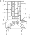
- FIG. 1 is a schematic configuration diagram of a camera system 100 according to one embodiment of the disclosure.
- the camera system 100 includes a camera body (image pickup apparatus) 110 and a lens apparatus (interchangeable lens) 200, and can capture a stereoscopic image.
- the camera body 110 includes an image sensor 111, an A/D converter 112, an image processing unit 113, a display unit 114, an operation unit 115, a memory 116, a camera control unit 117, and a camera mount 122.
- the lens apparatus 200 includes a right-eye optical system (first optical system) 201R, a left-eye optical system (second optical system) 201L, a lens mount (mount unit) 202, and a lens control unit 209, and is attachable to and detachable from the camera body 110.
- These two optical systems are arranged in parallel (symmetrically) and configured such that two image circles are imaged in parallel on the image sensor 111.
- These two optical systems are arranged horizontally and spaced by a predetermined distance (baseline length).
- the lens apparatus 200 is a lens apparatus for stereoscopic imaging that can capture two images having a parallax using two optical systems.
- the camera control unit 117 and the lens control unit 209 are electrically connected to each other.
- the object images including the right-eye image formed via the right-eye optical system 201R and the left-eye image formed via the left-eye optical system 201L are formed on the image sensor 111 in parallel.
- the image sensor 111 converts the captured object images (optical signals) into analog electric signals.
- the A/D converter 112 converts the analog electric signals output from the image sensor 111 into digital electric signals (image signals).
- the image processing unit 113 performs various image processing for the digital electric signals output from the A/D converter 112.
- the display unit 114 displays various information.
- the display unit 114 includes, for example, an electronic viewfinder or a liquid crystal panel.
- the operation unit 115 has a function as a user interface for the user to give an instruction to the camera system 100.
- the touch panel also constitutes the operation unit 115.
- the memory 116 includes, for example, a ROM, a RAM, and an HDD, and stores various data and programs such as image data that has been processed by the image processing unit 113.
- the camera control unit 117 includes, for example, a CPU, and integrally controls the entire camera system 100.
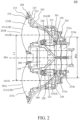
- FIG. 2 is a sectional view of the lens apparatus 200.
- FIG. 3 is an exploded perspective view of the lens apparatus 200 viewed from the object side.
- FIG. 4 is an exploded perspective view of the lens apparatus 200 viewed from the imaging plane side.
- each of the right-eye optical system 201R and the left-eye optical system 201L can capture an image at an angle of view higher than 180 degrees.
- Each optical system is a bending optical system having two reflective surfaces.
- each optical system includes a first lens 211 having a convex lens surface 211A on the object side disposed on the first optical axis OA1, a second lens 221 disposed on the second optical axis OA2, and third lenses 231a and 231b disposed on the third optical axis OA3.
- Each optical system has a first prism (first reflective surface) 220 that bends a light beam on the first optical axis OA1 and guides it to the second optical axis OA2, and a second prism (first reflective surface) 230 that bends the light beam on the second optical axis OA2 and guides it to the third optical axis OA3.
- the optical axis direction indicates a direction parallel to the first optical axis OA1, which is a direction extending toward the object side and the imaging plane side.
- Each optical system is fixed to a lens top base 300 by tightening screws or the like.
- the lens top base 300 is fixed to the lens bottom base 301 by tightening screws or the like.
- the lens top base 300 and the lens bottom base 301 function a base member where the right-eye optical system 201R, the left-eye optical system 201L, and a circuit board 310 are attached.
- the right-eye optical system 201R, the left-eye optical system 201L, and the circuit board 310 can move integrally with the base member in a first optical direction relative to the lens mount 202.
- the lens bottom base 301 is held movably in the optical axis direction while it is restricted from moving in a rotation direction by an unillustrated linear movement structure. Thereby, since each optical system is integrally movable in the optical axis direction, the right-eye optical system 201R and the left-eye optical system 201L can adjust their focus positions at the same time.
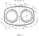
- FIG. 5 is a front view of the lens apparatus 200.
- FIG. 6 is a sectional view taken along a line A-A in FIG. 5 , illustrating the structure of the first lens 211 and its periphery.
- FIG. 7 illustrates a variation of the lens apparatus 200.
- FIG. 8 is a sectional view taken along a line B-B in FIG. 5 , illustrating the structure of the first lens 211 of the lens apparatus 200 and its periphery.
- the lens apparatus 200 includes an exterior cover member 203 and a front-surface exterior member (exterior member) 204.
- the exterior cover member 203 houses the right-eye optical system 201R and the left-eye optical system 201L.
- the front-surface exterior member 204 is screwed and fixed to the exterior cover member 203, and the front-surface exterior member 204 and the exterior cover member 203 can house the front side of the lens apparatus 200 so as to cover it.
- the front-surface exterior member 204 has openings (second openings) 204F into which the first lens (first lens) 211R of the right-eye optical system 201R and the first lens (second lens) 211L of the left-eye optical system 201L are inserted.
- the front-surface exterior member 204 has a shape that does not shield effective light beams of the right-eye optical system 201R and the left-eye optical system 201L each having an effective angle of view FOV higher than 180 degrees.
- Lens surfaces 211A on the object side of the first lenses 211R and 211L are incident surfaces of the effective light beams on the object side.
- an effective incident surface 211B When an effective incident surface 211B is set to the inside of an effective-incident-surface outer-diameter 211C of the lens surface 211A, a light beam having an angle of view of 180 degrees extends horizontally in a direction approximately orthogonal to the optical axis from the effective incident surface 211B.
- a light beam having an angle of view higher than 180 degrees is located on the imaging plane side of the effective incident surface 211B, and extends toward the imaging plane side as a position becomes farther from the first lens 211.
- the front-surface exterior member 204 and the cover member 213 are disposed on the imaging plane side of the effective incident surface 211B because they do not shield the light beam having the angle of view higher than 180 degrees.
- a right-eye area 20R is an area located on the right-eye optical system 201R side and a left-eye area 20L is an area located on the left-eye optical system 201L side with respect to a center point O between the right-eye optical system 201R and the left-eye optical system 201L.
- the front-surface exterior member 204 has an object-side surface 204A in the right-eye area 20R, which approaches the imaging plane as a position is separated from the first lens 211L of the left-eye optical system 201L so as not to shield the outermost effective light beam (thick dotted line portion in FIG. 8 ) of the left-eye optical system 201L.
- the front-surface exterior member 204 has an object-side surface 204B in the left-eye area 20L, which approaches the imaging plane as a position is separated from the first lens 211R of the right-eye optical system 201R so as not to shield the outermost effective light beam of the right-eye optical system 201R.
- the first lens 211L and its periphery viewed from the right-eye optical system 201R and the first lens 211R and its periphery viewed from the left-eye optical system 201L also have areas that shield part of mutual effective light beams.
- the front-surface exterior member 204 has wall portions 204C and 204D protruding toward the object side from the object-side surfaces 204A and 204B in order to form the openings 204F.
- the wall portion 204C has an arc shape approximately coaxial with the first lens 211R of the right-eye optical system 201R and does not shield the effective light beam of the right-eye optical system 201R, but shields part of the effective light beam of the left-eye optical system 201L.
- the wall portion 204D has an arc shape approximately coaxial with the first lens 211L of the left-eye optical system 201L and does not shield the effective light beam of the left-eye optical system 201L, but shields part of the effective light beam of the right-eye optical system 201R.
- the lens apparatus 200 includes a first lens holder 212 and a cover member 213.
- the first lens holder 212 holds the first lenses 211R and 211L.
- the cover member 213 covers the outer circumference portion of the lens surfaces 211A on the object side of the first lenses 211R and 211L, and has openings (first openings) 213A into which the first lenses 211R and 211L are inserted.
- the openings 213A are formed so as to expose the first lenses 211R and 211L when viewed from the optical axis direction.
- the boundary 211D is a boundary between the lens surface 211A and other surfaces or members.
- the boundary 211D may be a boundary between the lens surface 211A and a side surface 211E of the first lens 211, or as illustrated in FIG. 7 , a boundary between the lens surface 211A and an inner diameter tip portion having a caulking claw shape for caulking the first lenses 211R and 211L.
- the cover member 213 covers the boundary 211D. That is, the inner diameter of the opening 213A of the cover member 213 is smaller than the diameter of the boundary 211D.
- ⁇ A is the inner diameter of the opening 213A
- ⁇ B is the diameter of the boundary 211D
- the appearance quality can be improved by covering the boundary 211D.
- a groove portion 213B is formed in part of the inner circumference of the cover member 213.
- a convex portion 212A extending toward the outer circumference side is formed on part of the outer circumference of the first lens holder 212.
- the groove portion 213B and the convex portion 212A are assembled when they are located at positions where they do not overlap each other when viewed from the optical axis direction, and the convex portion 212Ais inserted into the groove portion 213B by rotating the cover member 213.
- the cover member 213 is positioned with the first lens holder 212 in the optical axis direction.
- the first lens holder 212 may be provided with a groove portion
- the cover member 213 may be provided with a convex portion.
- a predetermined gap (first gap) Y is formed in a (diameter) direction orthogonal to the optical axis direction between the first lens holder 212 and the cover member 213. Since the predetermined gap Y is smaller than the overlap amount X of the cover member 213, the cover member 213 can cover the boundary 211D even in a case where the first lens holder 212 or the cover member 213 moves by the predetermined gap Y.
- the cover member 213 is positioned with the first lens holder 212 in the optical axis direction and thus is integrally movable with the first lens holder 212 in the optical axis direction.
- the outer diameter of the cover member 213 is engaged with the inner diameter of the opening 204F of the front-surface exterior member 204.
- the gap (second gap) in the direction orthogonal to the optical axis direction formed between the front-surface exterior member 204 and the cover member 213 by this engagement is very small and smaller than the predetermined gap Y.
- the cover member 213 includes a rotation restricting key (projection) 213C
- the front-surface exterior member 204 includes a rotation restricting groove (groove portion) 204E corresponding to the rotation restricting key 213C.
- the rotation restricting key 213C is inserted into the rotation restricting groove 204E, and the cover member 213 is restricted from rotating.
- This structure can prevent the cover member 213 from rotating and coming off from the first lens holder 212.
- the cover member 213 may be provided with the rotation restricting groove, and the front-surface exterior member 204 may be provided with the rotation restricting key. That is, one of the cover member 213 and the front-surface exterior member 204 may include the rotation restricting key and the other may include the rotation restricting groove.
- An optical-axis-direction (OAD) sealing member 214 is a drip-proof and dust-proof member, is disposed between a surface (first surface) 213D on the imaging plane side of the cover member 213 and a surface (second surface) 212B on the object side facing the surface 213D of the first lens holder 212, and seals a space between the surfaces 213D and 212B.
- the surfaces 213D and 212B may be formed on the entire circumference but may be partially formed. Since the OAD sealing member 214 is sandwiched in the optical axis direction, the cover member 213 and the first lens holder 212 are biased in the optical axis direction, and unsteadiness (or backlash) in the optical axis direction can be reduced.
- the OAD sealing member 214 is disposed with a clearance (gap) larger than the predetermined gap Y with the cover member 213 and the first lens holder 212 in the direction orthogonal to the optical axis direction.
- the OAD sealing member 214 is made of an elastically deformable material, such as rubber or sponge, and can absorb the predetermined gap Y.
- a radial seal member 215 is a drip-proof and dust-proof member and is disposed while sandwiched between the cover member 213 and the opening 204F in the direction orthogonal to the optical axis direction.
- the radial seal member 215 on the right-eye optical system 201R side is disposed at a position that shields the effective light beam of the left-eye optical system 201L
- the radial seal member 215 on the left-eye optical system 201L side is disposed at a position that shields the effective light beam of the right-eye optical system 201R.
- the above-described structure can provide the lens apparatus 200 capable of maintaining the appearance quality, achieving both the dust-proof and drip-proof performance and the optical performance, and performing stereoscopic imaging at an angle of view higher than 180 degrees. Since the first lens holder 212 is not directly engaged with the opening 204F in the front-surface exterior member 204, even if the position of the first lens holder 212 is shifted by the influence of manufacturing errors or the like, the position needs no calibration. Therefore, the optical performance and the relative error between the right-eye optical system 201R and the left-eye optical system 201L do not change even if the front-surface exterior member 204 is incorporated.
- FIG. 9 illustrates a positional relationship between each optical axis of the lens apparatus 200 and the image circles on the image sensor 111.
- a right-eye image circle ICR with an effective angle of view formed by the right-eye optical system 201R and a left-eye image circle ICL with an effective angle of view formed by the left-eye optical system 201L are imaged in parallel on the image sensor 111.
- a diameter ⁇ D2 of the image circle and a spaced distance between the image circles may be set so that the image circles do not overlap each other.
- the center of the right-eye image circle ICR may be set to an approximate center of a right area that is made by dividing a light-receiving range of the image sensor 111 into left and right halves at the center, and the center of the left-eye image circle ICL may be set to an approximate center of the left area.
- Each optical system is a wide-angle fisheye lens.
- each optical system is a circumferential (all-around) fisheye lens
- the image formed on the imaging plane is a circular image reflecting a range of an angle of view higher than 180 degrees, and two circular images are formed on the left and right sides as illustrated in FIG. 9 .
- the image sensor 111 has a size of 24 mm in length ⁇ 36 mm in width
- the diameter ⁇ D2 of the image circle is 17 mm
- a distance L2 between the third optical axes OA3R and OA3L is 18 mm
- the length of the second optical axis is 21 mm.
- the lenses disposed on the third optical axis can be placed inside the lens mount 202 by making the diameter (fitting diameter relative to the camera body 110) ⁇ D of the lens mount 202 shorter than the baseline length L1, and the distance L2 between the third optical axes shorter than the diameter ⁇ D of the lens mount 202.
- an angle of view to obtain the stereoscopic effect is about 120 degrees, but a sense of discomfort remains when the field of view is 120 degrees and thus the angle of view is often widened to 180 degrees. Since the effective angle of view exceeds 180 degrees in this embodiment, the diameter ⁇ D2 of the image circle in this embodiment is larger than the diameter ⁇ D3 of the image circle in the range of the angle of view of 180 degrees.
- FIG. 10 illustrates the reflection of the left-eye optical system 201L when the image is captured with the right-eye optical system 201R.
- the wall portion 204D of the front-surface exterior member 204 is imaged inside the diameter ⁇ D2 of the image circle, which is the effective angle of view, but is not imaged at an angle of view of 180 degrees, and is imaged outside the diameter ⁇ D3 of the image circle in the range of the angle of view of 180 degrees. Therefore, VR viewing is not affected in the range of the angle of view of 180 degrees.
- the first lens 211L of the left-eye optical system 201L in the left-eye area 20L, the cover member 213, and the wall portion 204D of the front-surface exterior member 204 which are imaged in the actual effective imaging range as illustrated in FIG. 10 .
- Only the first lens 211L is imaged within the image circle at the angle of view of 180 degrees (inside the diameter ⁇ D3), but the cover member 213 and the wall portion 204D are located outside the image circle at the angle of view of 180 degrees.
- the reflection of the wall portion 204D is imaged outside (on the left side illustrated in FIG.
- the wall portion 204D is located within the effective angle of view, it is located so as to have almost no influence on imaging in the actual VR application.
- FIG. 11 is an external perspective view of the lens cap 400 attached to the lens apparatus 200.
- FIG. 12 is an external perspective view of the lens cap 400 when attached to the lens apparatus 200 (not illustrated).
- FIG. 13 is an external perspective view of the lens cap 400 when detached from the lens apparatus 200 (not illustrated).
- FIG. 14 is an exploded perspective view of the lens cap 400.
- the lens cap 400 includes a base 401, sliders (slider members) 402A and 402B, and springs 403A and 403B.
- the sliders 402A and 402B have the same shape, are connected in a phase rotated by 180 degrees, and are incorporated in the base 401.
- the slider 402A (402B) includes an operation unit 402A2 (402B2), a connection portion 402A3 (402B3) that fits the lens apparatus 200, and a stopper portion 402A4 (402B4) that abuts on the base 401. Further, the slider 402A (402B) includes a connecting portion arranged between the optical axis of the first lens 211R and the optical axis of the first lens 211L.
- the slider 402A (402B) is urged to the side of the operation unit 402A2 (402B2) by the spring 403A (403B) incorporated in the base 401.
- the base 401 and the stopper portion 402A4 (402B4) are in contact with each other while the slider 402A (402B) is urged.
- the connection portions 402A3 and 402B3 are opened and closed, and the lens cap 400 can be attached to and detached from the lens apparatus 200.
- the lens cap 400 can be attached to and detached from the lens apparatus 200 by simply pressing one of the operation units.
- FIG. 15 is a sectional view of the lens cap 400 and the first lens 211 when the lens cap 400 is attached.
- FIG. 16 is a side view of the sliders 402A and 402B and the first lens 211 when the lens cap 400 is attached.
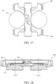
- FIG. 17 is a top view of the sliders 402A and 402B and the first lens 211 when the lens cap 400 is attached.
- the sliders 402A and 402B are arranged between the first lenses 211R and 211L disposed on the first optical axis OA1, and the sliders 402A and 402B and the first lenses 211R and 211L are provided on the same plane orthogonal to the optical axis direction. As a result, the thickness in the optical axis direction can be reduced by the thickness of the slider 402. Further, the operation units 402A2 and 402B2 are arranged at the center between the first lenses 211R and 211L. This makes it possible to realize smooth operability.
- FIG. 18 is a sectional view of the lens cap 400 and the first lens 211 when the lens cap 400 according to another example is attached.
- the sliders 402A and 402B are arranged between the first lenses 211R and 211L disposed on the first optical axis OA1, and the sliders 402A and 402B and the first lenses 211R and 211R are not provided on the same plane orthogonal to the optical axis direction.
- the thickness of the sliders 402A and 402B becomes thicker, so that the weight becomes heavier as the lens apparatus 200 becomes larger, and even if the strength of the sliders 402Aand 402B is insufficient due to a drop test or the like, the strength can be improved.
- connection portions 203A, 203B, 203C, and 203D are respectively an external perspective view, an external side view, and an external bottom view of the lens apparatus 200.
- the angle of view of the lens apparatus 200 is the range indicated by the dotted line G, and exceeds 180 degrees toward the object side. If a component or the like including a connection portion is provided on the object side from the range indicated by the dotted line G, it will be reflected in the image.
- the connection portions 203A, 203B, 203C, and 203D are provided outside the angle of view indicated by the dotted line G.
- connection portions 203A, 203B, 203C, and 203D are provided in the direction visible from the external direction, but the lens cap 400 may be fitted to the lens apparatus 200 in the direction invisible from the external direction, that is, from the inside. Even in that case, by arranging the connection portions 203A, 203B, 203C, and 203D outside the angle of view indicated by the dotted line G, it is possible to prevent the connection portion 203A, 203B, 203C, and 203D from being reflected in the image.
- the lens system control unit 209 is arranged inside the interchangeable lens 200 as a circuit board 310 as illustrated in FIGs. 1 and 22 .
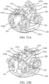
- a diaphragm apparatus (electronic member) 240 is arranged in each of the right eye optical system 201R and the left eye optical system 201L as illustrated in FIG. 2 , and electronically controlling a drive source 320 such as a stepping motor (see FIGs. 23A and 23B ) can set the desired aperture diameter.
- a circuit board 310 for electronically controlling the aperture device 240 is arranged on the lens top base 300.
- the circuit board 310 includes a plurality of electric elements 310A for communication with the camera body 110 and control of electronic components, and is electrically connected by a wiring unit.
- a flexible substrate (second flexible substrate) 330A is provided for communicating with the electronic component to be controlled.
- the flexible substrate 330A is electrically connected to the diaphragm apparatus 240 and the drive source 320 such as a stepping motor.
- the circuit board 310 is provided with a connector (second connector) 310B for electrically connecting the flexible board 330A.
- the connector 310B is arranged point-symmetrically around the axis of the lens mount 202.
- a flexible substrate (first flexible substrate) 330B is provided for communicating with the camera body 110.
- the flexible substrate 330B is electrically connected to an electrical contact portion (communication unit) 202A arranged on the lens mount 202 in order to communicate with the camera body 110.
- a connector (first connector) 310C for electrically connecting the flexible board 330B is arranged on the circuit board 310.
- the flexible substrate 330B electrically connects the electric contact portion 202A and the connector 310C, and extends in a direction of a lens mount axis MA.
- the connectors 310B and 310C are arranged not to overlap with the first lens 211 and the first lens holder 212 disposed closest to the object in each of the right eye optical system 201R and the left eye optical system 201L.
- the circuit board 310 can communicate with the camera body 110 through the lens mount 202, and can control electronic components such as the aperture device 240 provided inside the interchangeable lens 200.
- the circuit board 310 electronically controls the aperture device 240, but if there is an object to be electronically driven, such as when the lens is driven for vibration isolation or autofocus, the circuit board 310 can play the role of electronic control.
- the circuit board 310 is fixed to the lens top base 300 by tightening screws or the like.
- the lens top base 300 and the lens bottom base 301 are a base member of a binocular optical system unit, and the right eye optical system 201R and the left eye optical system 201L can move forward and backward in the optical axis direction integrally with the base member.
- the circuit board 310 is positioned between the two first optical axes OA1R and OA1L of the right eye optical system 201R and the left eye optical system 201L (position sandwiched between the two first optical axes), and is arranged on the object side of the second optical axes OA2R and OA2L. Further, the circuit board 310 is arranged on the axis of the lens mount 202 (on the lens mount axis MA). Additionally, the substrate surface of the circuit board 310 (the surface on which the electric element 310A is arranged) is perpendicular to the lens mount axis MA.
- the circuit board 310 is arranged at a position overlapping the lens surface 211A on the object side of the first lens 211 arranged closer to the object than the circuit board 310 when viewed from the first optical axis direction or the direction of the lens mount axis MA.
- the circuit board 310 is arranged closer to the image plane side than the lens surface 211A, and is arranged at a position sandwiched between the side surfaces of the lens having a small diameter.
- the circuit board 310 may be sandwiched by another lens arranged closer the image plane side than the first lens 211.
- the circuit board 310 is arranged at a position sandwiched between the side surfaces of the lens member arranged closer the image plane side than the lens surface 211A. Further, the circuit board 310 is arranged on an extension line of the third optical axis OA3. Additionally, the circuit board 310 is arranged in a region where the second prism 230, which is an optical member forming the second optical axis OA2, and the lens mount axis MA overlap each other when viewed from the direction of the lens mount axis MA.
- Arranging the circuit board 310 at such a position can effectively utilize the space between the two optical systems created by securing the distance L1 between the first optical axes, which is an appropriate baseline length for VR stereoscopic viewing, and can make a space-efficient arrangement. It is also advantageous for miniaturization of the interchangeable lens 200.
- the third optical axis OA3 is inside the diameter of the lens mount 202, and projects to the outer diameter side of the main body of the interchangeable lens 200 by the second optical axis OA2 to secure the baseline length.
- the inclusion member such as the first prism 220, the second prism 230, and a holding frame for holding them, and the bottom base 301 may be affected. As a result, the degree of freedom in design is reduced and the interchangeable lens 200 becomes large.
- the second optical axis OA2 in an attempt to arrange a donut-shaped or C-shaped circuit board near the lens mount as in the conventional case, it is conceivable to arrange the second optical axis OA2 closer to the object in order to secure space.
- the second optical axis OA2 if the second optical axis OA2 is arranged closer to the object, the overall length of the optical system increases, and the outer diameter of the lens itself also increases, which leads to an increase in the size of the interchangeable lens.
- arranging the second optical axis OA2 closer to the image plane side can shorten the total length of the lens and can reduce the diameter of the lens, which can contribute to the miniaturization of the interchangeable lens.
- the shape of the board surface of the circuit board 310 is not a donut shape or a C-shaped shape as in the conventional case, but a substantially rectangular shape, so that the efficient arrangement and wiring of the electric element 310A in the circuit board 310 can be improved. Additionally, the substantially rectangular shape can improve the efficiency of punching by the press in the manufacturing process as compared with the donut shape and the C-shaped shape. Cost reduction can be achieved by increasing the number of sheets taken by the press.
- FIG. 22 is a front view of the interchangeable lens 200 in a state in which the front extender member 204 and the cover 213 are removed when viewed from the object side in the direction of the lens mount axis MA.
- the circuit board 310 is fixed to the lens top base 300 at a fixing portion 310D by tightening screws or the like.
- the fixing method may be screw tightening or adhesion.
- the fixed portion 310D is arranged not to overlap with the first lens 211, which is disposed closer to the object than the circuit board 310, and the first lens holder 212 when viewed from the object side in the direction of the first optical axis OA1.
- the connectors 310B and 310C are arranged not to overlap with the first lens 211 and the first lens holder 212.
- the circuit board 310 can be incorporated in a state where only the front exterior 204 and the cover 213 are not assembled, and can be fixed or connected to a flexible board. Then, after fixing and connecting the circuit board 310, the front exterior 204 and the cover 213 can be assembled to complete the interchangeable lens 200. Even if the circuit board 310 needs to be replaced due to a defect of the circuit board 310, the circuit board 310 can be relatively quickly replaced.
- the circuit board 310 is arranged on the lens mount axis MA. Additionally, when viewed from the direction of the lens mount axis MA, it is desirable that at least a part of the electric element 310A provided on the circuit board 310 is arranged inside the diameter ⁇ D of the lens mount 202. Moreover, when viewed from a direction orthogonal to each of the distance direction (direction of the baseline length L1) between the two first optical axes OA1R and OA1L and the first optical axis direction, it is desirable that the circuit board 310 is arranged between the two first optical axes OA1R and OA1L. As a result, the interchangeable lens 200 can be further miniaturized.
- the fixing portion 310D for mounting the circuit board 310 is also arranged inside the diameter ⁇ D.
- the outside of the diameter ⁇ D may be preferable in terms of design. Accordingly, at least the electric element 310A is located inside the diameter ⁇ D, so that the configuration can be made more advantageous for miniaturization.
- FIGs. 23A and 23B are perspective views of a main part of the interchangeable lens 200 as viewed from two different directions.
- FIGs. 23A and 23B illustrates only the lens mount 202 and the circuit board 310, their peripheral components such as the flexible substrates 330A and 330B, the lens top base 300 and the lens bottom base 301 of the base member, and the like.
- FIG. 24 is a sectional view illustrating a path of the flexible substrate 330B.
- the flexible board 330B is electrically connected to the electrical contact portion 202A of the lens mount 202 and the connector 310C of the circuit board 310, and can communicate with the camera body 110.
- the flexible substrate 330B extends in the direction of the lens mount axis MA.
- the lens bottom base 301 is arranged as the base member in the space where the donut-shaped or C-shaped circuit board is arranged as in the conventional case.
- the lens bottom base 301 includes a mechanism for moving the optical system in the optical axis direction in the vicinity of the outer periphery thereof, and serves as a barrier when connecting the flexible substrate 330B from the lens mount 202 to the circuit board 310. In this embodiment, as illustrated in FIGs.
- a through hole 301A is formed on the lens bottom base 301, and the flexible substrate 330B is configured to pass through the through hole 301A.
- FIG. 25 is a front view of the interchangeable lens 200 to show the arrangement of the circuit board 310 as another example of this embodiment, and is a view of the main part when viewed from the object side in the direction of the lens mount axis MA.
- FIG. 26 is a sectional view of the interchangeable lens 200 to show the arrangement of the circuit board 310 as another example, and is a view of the main part when viewed from a direction orthogonal to each of the direction of the baseline length and the direction of the first optical axis OA.
- the substrate surface of the circuit board 310 (surface on which the electric element 310A is arranged) is arranged so as to be parallel to each of the direction of the baseline length direction and the first optical axis OA1, it is possible to arrange the circuit board 310 in a saved space. Even in this case, as illustrated in FIG. 25 , since at least the electric element 310A is arranged inside the diameter ⁇ D of the lens mount 202, the configuration advantageous for miniaturization can be obtained. Further, as illustrated in FIG.
- the circuit board 310 is arranged to be sandwiched by the first optical axis OA1 (OA1R, OA1L) when viewed from directions orthogonal to each of the direction of the baseline length and the direction of the first optical axis OA. Furthermore, when viewed from directions orthogonal to each of the direction of the baseline length and the direction of the first optical axis OA, the circuit board 310 is arranged to overlap with the first lens 211 and the second prism 230 which is an optical member forming the second optical axis OA2. Arranging in this way can achieve a more space-efficient arrangement.
- a lens apparatus (200) includes a lens (211R,211L) disposed closest to an object, a holder (212) holding the lens, a cover (213) having a first opening (213A) to expose the lens when viewed from an optical axis direction of the lens and being positioned with the holder in the optical axis direction, and an exterior member (204) having a second opening (204F) to engage with an outer diameter of the cover.
- a first gap in a diameter direction orthogonal to the optical axis direction formed between the holder and the cover is larger than a second gap in the diameter direction formed between the exterior member and the cover.
Abstract
Description
- The disclosure relates to a lens apparatus.
- An interchangeable lens for stereoscopic photography has conventionally been known as an application of one of interchangeable lens systems.
Japanese Patent Laid-Open No. 2012-3022 - In viewing with a VR goggle, it is desirable that an angle of view of a moving or still image is 180 degrees or higher in order to obtain not only a three-dimensional effect but also a realistic effect. In order to provide an image with an angle of view of at least 180 degrees in consideration of manufacturing errors and the like, it is desirable that an imaging lens can capture an image at an angle of view higher than 180 degrees.
- However, the lens disclosed in
Japanese Patent Laid-Open No. 2012-3022 - The present invention provides a lens apparatus capable of maintaining appearance quality, achieving both dust-proof and drip-proof performance and optical performance, and performing stereoscopic imaging at an angle of view higher than 180 degrees.
- The present invention in its first aspect provides a lens apparatus as specified in claims 1 to 30.
- The present invention in its second aspect provides a lens apparatus as specified in claims 31 to 34.
- The present invention in its third aspect provides an image apparatus as specified in claims 35 and 36.
- The present invention in its fourth aspect provides a lens apparatus as specified in claims 37 to 43.
- Other aspects of the present invention will become apparent from the following description and the attached drawings.
-
-
FIG. 1 is a schematic configuration diagram of a camera system according to one embodiment of the disclosure. -
FIG. 2 is a sectional view of a lens apparatus. -
FIG. 3 is an exploded perspective view of the lens apparatus viewed from an object side. -
FIG. 4 is an exploded perspective view of the lens apparatus viewed from an imaging plane side. -
FIG. 5 is a front view of the lens apparatus. -
FIG. 6 is a sectional view taken along a line A-A inFIG. 5 . -
FIG. 7 illustrates a variation of the lens apparatus. -
FIG. 8 is a sectional view taken along a line B-B ofFIG. 5 . -
FIG. 9 illustrates a positional relationship between each optical axis and an image circle on an image sensor. -
FIG. 10 illustrates reflection of a left-eye optical system in a case where an image is captured by a right-eye optical system. -
FIG. 11 is an external perspective view of a lens cap attached to the lens apparatus. -
FIG. 12 is an external perspective view of the lens cap when attached to the lens apparatus. -
FIG. 13 is an external perspective view of the lens cap when detached from the lens apparatus. -
FIG. 14 is an exploded perspective view of the lens cap. -
FIG. 15 is a sectional view of the lens cap and the first lens when the lens cap is attached. -
FIG. 16 is a side view of the sliders and the first lens when the lens cap is attached. -
FIG. 17 is a top view of the sliders and the first lens when the lens cap is attached. -
FIG. 18 is a sectional view of the lens cap and the first lens when the lens cap according to another example is attached. -
FIG. 19 is an external perspective view of the lens apparatus. -
FIG. 20 is an external side view of the lens apparatus. -
FIG. 21 is an external bottom view of the lens apparatus. -
FIG. 22 is a front view of the lens apparatus in a state in which a front extender member and a cover are removed. -
FIGs. 23A and 23B are perspective views of a main part of the lens apparatus. -
FIG. 24 is a sectional view illustrating a path of a flexible substrate. -
FIG. 25 is a front view of the lens apparatus as another example. -
FIG. 26 is a sectional view of the lens apparatus as another example. - Referring now to the accompanying drawings, a detailed description will be given of embodiments according to the disclosure. Corresponding elements in respective figures will be designated by the same reference numerals, and a duplicate description thereof will be omitted.
-
FIG. 1 is a schematic configuration diagram of acamera system 100 according to one embodiment of the disclosure. Thecamera system 100 includes a camera body (image pickup apparatus) 110 and a lens apparatus (interchangeable lens) 200, and can capture a stereoscopic image. - The
camera body 110 includes animage sensor 111, an A/D converter 112, animage processing unit 113, adisplay unit 114, anoperation unit 115, amemory 116, acamera control unit 117, and acamera mount 122. - The
lens apparatus 200 includes a right-eye optical system (first optical system) 201R, a left-eye optical system (second optical system) 201L, a lens mount (mount unit) 202, and alens control unit 209, and is attachable to and detachable from thecamera body 110. These two optical systems are arranged in parallel (symmetrically) and configured such that two image circles are imaged in parallel on theimage sensor 111. These two optical systems are arranged horizontally and spaced by a predetermined distance (baseline length). When viewed from the imaging plane side (image side), a right image captured by the right-eyeoptical system 201R is recorded as a moving or still image for the right eye, and a left image captured by the left-left-eyeoptical system 201L is recorded as a moving or still image for the left eye. The reproduced moving or still images are viewed with a 3D display, VR goggles, or the like, so that the right-eye image is displayed on the right eye of the viewer and the left-eye image is displayed on the left eye of the viewer. At this time, images having a parallax are projected on the right and left eyes depending on the baseline length and provide the viewer with a stereoscopic effect. Thus, thelens apparatus 200 is a lens apparatus for stereoscopic imaging that can capture two images having a parallax using two optical systems. - When the
lens apparatus 200 is attached to thecamera body 110 via thelens mount 202 and thecamera mount 122, thecamera control unit 117 and thelens control unit 209 are electrically connected to each other. - The object images including the right-eye image formed via the right-eye
optical system 201R and the left-eye image formed via the left-eyeoptical system 201L are formed on theimage sensor 111 in parallel. Theimage sensor 111 converts the captured object images (optical signals) into analog electric signals. The A/D converter 112 converts the analog electric signals output from theimage sensor 111 into digital electric signals (image signals). Theimage processing unit 113 performs various image processing for the digital electric signals output from the A/D converter 112. - The
display unit 114 displays various information. Thedisplay unit 114 includes, for example, an electronic viewfinder or a liquid crystal panel. Theoperation unit 115 has a function as a user interface for the user to give an instruction to thecamera system 100. In the case where thedisplay unit 114 has a touch panel, the touch panel also constitutes theoperation unit 115. - The
memory 116 includes, for example, a ROM, a RAM, and an HDD, and stores various data and programs such as image data that has been processed by theimage processing unit 113. - The
camera control unit 117 includes, for example, a CPU, and integrally controls theentire camera system 100. -
FIG. 2 is a sectional view of thelens apparatus 200.FIG. 3 is an exploded perspective view of thelens apparatus 200 viewed from the object side.FIG. 4 is an exploded perspective view of thelens apparatus 200 viewed from the imaging plane side. - In the following description, a description of the right-eye
optical system 201R will be given R at the end of the reference numeral, and a description of the left-eyeoptical system 201L will be given L at the end of the reference numeral. In the description common to both the right-eyeoptical system 201R and the left-eyeoptical system 201L, neither R nor L will be added to the end of the reference numeral. Each of the right-eyeoptical system 201R and the left-eyeoptical system 201L can capture an image at an angle of view higher than 180 degrees. Each optical system is a bending optical system having two reflective surfaces. In each optical system, a first optical axis OA1, a second optical axis OA2 approximately orthogonal to the first optical axis OA1, and a third optical axis OA3 parallel to the first optical axis OA1 are set in this order from the object side. Each optical system includes afirst lens 211 having aconvex lens surface 211A on the object side disposed on the first optical axis OA1, asecond lens 221 disposed on the second optical axis OA2, andthird lenses - Each optical system is fixed to a
lens top base 300 by tightening screws or the like. Thelens top base 300 is fixed to thelens bottom base 301 by tightening screws or the like. Thelens top base 300 and thelens bottom base 301 function a base member where the right-eyeoptical system 201R, the left-eyeoptical system 201L, and acircuit board 310 are attached. The right-eyeoptical system 201R, the left-eyeoptical system 201L, and thecircuit board 310 can move integrally with the base member in a first optical direction relative to thelens mount 202. Thelens bottom base 301 is held movably in the optical axis direction while it is restricted from moving in a rotation direction by an unillustrated linear movement structure. Thereby, since each optical system is integrally movable in the optical axis direction, the right-eyeoptical system 201R and the left-eyeoptical system 201L can adjust their focus positions at the same time. -
FIG. 5 is a front view of thelens apparatus 200.FIG. 6 is a sectional view taken along a line A-A inFIG. 5 , illustrating the structure of thefirst lens 211 and its periphery.FIG. 7 illustrates a variation of thelens apparatus 200.FIG. 8 is a sectional view taken along a line B-B inFIG. 5 , illustrating the structure of thefirst lens 211 of thelens apparatus 200 and its periphery. - The
lens apparatus 200 includes anexterior cover member 203 and a front-surface exterior member (exterior member) 204. Theexterior cover member 203 houses the right-eyeoptical system 201R and the left-eyeoptical system 201L. The front-surface exterior member 204 is screwed and fixed to theexterior cover member 203, and the front-surface exterior member 204 and theexterior cover member 203 can house the front side of thelens apparatus 200 so as to cover it. - The front-
surface exterior member 204 has openings (second openings) 204F into which the first lens (first lens) 211R of the right-eyeoptical system 201R and the first lens (second lens) 211L of the left-eyeoptical system 201L are inserted. The front-surface exterior member 204 has a shape that does not shield effective light beams of the right-eyeoptical system 201R and the left-eyeoptical system 201L each having an effective angle of view FOV higher than 180 degrees. Lens surfaces 211A on the object side of thefirst lenses diameter 211C of thelens surface 211A, a light beam having an angle of view of 180 degrees extends horizontally in a direction approximately orthogonal to the optical axis from the effective incident surface 211B. A light beam having an angle of view higher than 180 degrees is located on the imaging plane side of the effective incident surface 211B, and extends toward the imaging plane side as a position becomes farther from thefirst lens 211. Thus, the front-surface exterior member 204 and thecover member 213 are disposed on the imaging plane side of the effective incident surface 211B because they do not shield the light beam having the angle of view higher than 180 degrees. - Now, as illustrated in
FIG. 5 , assume that a right-eye area 20R is an area located on the right-eyeoptical system 201R side and a left-eye area 20L is an area located on the left-eyeoptical system 201L side with respect to a center point O between the right-eyeoptical system 201R and the left-eyeoptical system 201L. Then, the front-surface exterior member 204 has an object-side surface 204A in the right-eye area 20R, which approaches the imaging plane as a position is separated from thefirst lens 211L of the left-eyeoptical system 201L so as not to shield the outermost effective light beam (thick dotted line portion inFIG. 8 ) of the left-eyeoptical system 201L. The front-surface exterior member 204 has an object-side surface 204B in the left-eye area 20L, which approaches the imaging plane as a position is separated from thefirst lens 211R of the right-eyeoptical system 201R so as not to shield the outermost effective light beam of the right-eyeoptical system 201R. However, thefirst lens 211L and its periphery viewed from the right-eyeoptical system 201R and thefirst lens 211R and its periphery viewed from the left-eyeoptical system 201L also have areas that shield part of mutual effective light beams. - The front-
surface exterior member 204 haswall portions side surfaces openings 204F. Thewall portion 204C has an arc shape approximately coaxial with thefirst lens 211R of the right-eyeoptical system 201R and does not shield the effective light beam of the right-eyeoptical system 201R, but shields part of the effective light beam of the left-eyeoptical system 201L. Thewall portion 204D has an arc shape approximately coaxial with thefirst lens 211L of the left-eyeoptical system 201L and does not shield the effective light beam of the left-eyeoptical system 201L, but shields part of the effective light beam of the right-eyeoptical system 201R. - As illustrated in
FIG. 6 , thelens apparatus 200 includes afirst lens holder 212 and acover member 213. Thefirst lens holder 212 holds thefirst lenses cover member 213 covers the outer circumference portion of the lens surfaces 211A on the object side of thefirst lenses first lenses openings 213A are formed so as to expose thefirst lenses - There is a
boundary 211D with thelens surface 211A on the outer circumference side of the effective-incident-surface outer-diameter 211C of thefirst lens 211. Theboundary 211D is a boundary between thelens surface 211A and other surfaces or members. For example, theboundary 211D may be a boundary between thelens surface 211A and aside surface 211E of thefirst lens 211, or as illustrated inFIG. 7 , a boundary between thelens surface 211A and an inner diameter tip portion having a caulking claw shape for caulking thefirst lenses - The
cover member 213 covers theboundary 211D. That is, the inner diameter of theopening 213A of thecover member 213 is smaller than the diameter of theboundary 211D. Where ΦA is the inner diameter of theopening 213A and ΦB is the diameter of theboundary 211D, an overlap amount X on one side is expressed by the following expression (1).
- The appearance quality can be improved by covering the
boundary 211D. - A
groove portion 213B is formed in part of the inner circumference of thecover member 213. Aconvex portion 212A extending toward the outer circumference side is formed on part of the outer circumference of thefirst lens holder 212. Thegroove portion 213B and theconvex portion 212A are assembled when they are located at positions where they do not overlap each other when viewed from the optical axis direction, and the convex portion 212Ais inserted into thegroove portion 213B by rotating thecover member 213. Thereby, thecover member 213 is positioned with thefirst lens holder 212 in the optical axis direction. Thefirst lens holder 212 may be provided with a groove portion, and thecover member 213 may be provided with a convex portion. - A predetermined gap (first gap) Y is formed in a (diameter) direction orthogonal to the optical axis direction between the
first lens holder 212 and thecover member 213. Since the predetermined gap Y is smaller than the overlap amount X of thecover member 213, thecover member 213 can cover theboundary 211D even in a case where thefirst lens holder 212 or thecover member 213 moves by the predetermined gap Y. - The
cover member 213 is positioned with thefirst lens holder 212 in the optical axis direction and thus is integrally movable with thefirst lens holder 212 in the optical axis direction. The outer diameter of thecover member 213 is engaged with the inner diameter of theopening 204F of the front-surface exterior member 204. The gap (second gap) in the direction orthogonal to the optical axis direction formed between the front-surface exterior member 204 and thecover member 213 by this engagement is very small and smaller than the predetermined gap Y. - The
cover member 213 includes a rotation restricting key (projection) 213C, and the front-surface exterior member 204 includes a rotation restricting groove (groove portion) 204E corresponding to the rotation restricting key 213C. Thereby, when the front-surface exterior member 204 is incorporated, the rotation restricting key 213C is inserted into therotation restricting groove 204E, and thecover member 213 is restricted from rotating. This structure can prevent thecover member 213 from rotating and coming off from thefirst lens holder 212. Thecover member 213 may be provided with the rotation restricting groove, and the front-surface exterior member 204 may be provided with the rotation restricting key. That is, one of thecover member 213 and the front-surface exterior member 204 may include the rotation restricting key and the other may include the rotation restricting groove. - An optical-axis-direction (OAD) sealing
member 214 is a drip-proof and dust-proof member, is disposed between a surface (first surface) 213D on the imaging plane side of thecover member 213 and a surface (second surface) 212B on the object side facing thesurface 213D of thefirst lens holder 212, and seals a space between thesurfaces surfaces OAD sealing member 214 is sandwiched in the optical axis direction, thecover member 213 and thefirst lens holder 212 are biased in the optical axis direction, and unsteadiness (or backlash) in the optical axis direction can be reduced. - In order to maintain the predetermined gap Y, the
OAD sealing member 214 is disposed with a clearance (gap) larger than the predetermined gap Y with thecover member 213 and thefirst lens holder 212 in the direction orthogonal to the optical axis direction. TheOAD sealing member 214 is made of an elastically deformable material, such as rubber or sponge, and can absorb the predetermined gap Y. - A
radial seal member 215 is a drip-proof and dust-proof member and is disposed while sandwiched between thecover member 213 and theopening 204F in the direction orthogonal to the optical axis direction. Theradial seal member 215 on the right-eyeoptical system 201R side is disposed at a position that shields the effective light beam of the left-eyeoptical system 201L, and theradial seal member 215 on the left-eyeoptical system 201L side is disposed at a position that shields the effective light beam of the right-eyeoptical system 201R. - The above-described structure can provide the
lens apparatus 200 capable of maintaining the appearance quality, achieving both the dust-proof and drip-proof performance and the optical performance, and performing stereoscopic imaging at an angle of view higher than 180 degrees. Since thefirst lens holder 212 is not directly engaged with theopening 204F in the front-surface exterior member 204, even if the position of thefirst lens holder 212 is shifted by the influence of manufacturing errors or the like, the position needs no calibration. Therefore, the optical performance and the relative error between the right-eyeoptical system 201R and the left-eyeoptical system 201L do not change even if the front-surface exterior member 204 is incorporated. -
FIG. 9 illustrates a positional relationship between each optical axis of thelens apparatus 200 and the image circles on theimage sensor 111. - A right-eye image circle ICR with an effective angle of view formed by the right-eye
optical system 201R and a left-eye image circle ICL with an effective angle of view formed by the left-eyeoptical system 201L are imaged in parallel on theimage sensor 111. A diameter ΦD2 of the image circle and a spaced distance between the image circles may be set so that the image circles do not overlap each other. For example, the center of the right-eye image circle ICR may be set to an approximate center of a right area that is made by dividing a light-receiving range of theimage sensor 111 into left and right halves at the center, and the center of the left-eye image circle ICL may be set to an approximate center of the left area. - Each optical system is a wide-angle fisheye lens. In this embodiment, each optical system is a circumferential (all-around) fisheye lens, and the image formed on the imaging plane is a circular image reflecting a range of an angle of view higher than 180 degrees, and two circular images are formed on the left and right sides as illustrated in
FIG. 9 . The longer the distance (baseline length) L1 between the first optical axis OA1R of the right-eyeoptical system 201R and the first optical axis OA1L of the left-eyeoptical system 201L is, the more significant the stereoscopic effect becomes during viewing. For example, assume that theimage sensor 111 has a size of 24 mm in length × 36 mm in width, the diameter ΦD2 of the image circle is 17 mm, a distance L2 between the third optical axes OA3R and OA3L is 18 mm, and the length of the second optical axis is 21 mm. When each optical system is arranged so that the second optical axis extends in the horizontal direction, the baseline length L1 becomes 60 mm, which is almost equal to the eye width of an adult. The lenses disposed on the third optical axis can be placed inside thelens mount 202 by making the diameter (fitting diameter relative to the camera body 110) ΦD of thelens mount 202 shorter than the baseline length L1, and the distance L2 between the third optical axes shorter than the diameter ΦD of thelens mount 202. In VR viewing, it is said that an angle of view to obtain the stereoscopic effect is about 120 degrees, but a sense of discomfort remains when the field of view is 120 degrees and thus the angle of view is often widened to 180 degrees. Since the effective angle of view exceeds 180 degrees in this embodiment, the diameter ΦD2 of the image circle in this embodiment is larger than the diameter ΦD3 of the image circle in the range of the angle of view of 180 degrees. -
FIG. 10 illustrates the reflection of the left-eyeoptical system 201L when the image is captured with the right-eyeoptical system 201R. Thewall portion 204D of the front-surface exterior member 204 is imaged inside the diameter ΦD2 of the image circle, which is the effective angle of view, but is not imaged at an angle of view of 180 degrees, and is imaged outside the diameter ΦD3 of the image circle in the range of the angle of view of 180 degrees. Therefore, VR viewing is not affected in the range of the angle of view of 180 degrees. For example, within the effective angle of view of the right-eyeoptical system 201R, there are thefirst lens 211L of the left-eyeoptical system 201L in the left-eye area 20L, thecover member 213, and thewall portion 204D of the front-surface exterior member 204, which are imaged in the actual effective imaging range as illustrated inFIG. 10 . Only thefirst lens 211L is imaged within the image circle at the angle of view of 180 degrees (inside the diameter ΦD3), but thecover member 213 and thewall portion 204D are located outside the image circle at the angle of view of 180 degrees. The reflection of thewall portion 204D is imaged outside (on the left side illustrated inFIG. 10 ) even when viewed in the horizontal direction from the vertex portion of thefirst lens 211L. In the case of image processing or image editing, if the outside of the vertex portion indicated by a straight line Z of thefirst lens 211L is cut, which is always reflected due to the specifications, the reflection of thewall portion 204D will not be affected. This is similarly applied to the reflection of the right-eyeoptical system 201R when an image is captured with the left-eyeoptical system 201L. As described above, although thewall portion 204D is located within the effective angle of view, it is located so as to have almost no influence on imaging in the actual VR application. - A structure of a
lens cap 400 that is attachable to and detachable from thelens apparatus 200 with one action will be described below.FIG. 11 is an external perspective view of thelens cap 400 attached to thelens apparatus 200.FIG. 12 is an external perspective view of thelens cap 400 when attached to the lens apparatus 200 (not illustrated).FIG. 13 is an external perspective view of thelens cap 400 when detached from the lens apparatus 200 (not illustrated).FIG. 14 is an exploded perspective view of thelens cap 400. - The
lens cap 400 includes abase 401, sliders (slider members) 402A and 402B, and springs 403A and 403B. Thesliders base 401. Theslider 402A (402B) includes an operation unit 402A2 (402B2), a connection portion 402A3 (402B3) that fits thelens apparatus 200, and a stopper portion 402A4 (402B4) that abuts on thebase 401. Further, theslider 402A (402B) includes a connecting portion arranged between the optical axis of thefirst lens 211R and the optical axis of thefirst lens 211L. Additionally, theslider 402A (402B) is urged to the side of the operation unit 402A2 (402B2) by the spring 403A (403B) incorporated in thebase 401. Thebase 401 and the stopper portion 402A4 (402B4) are in contact with each other while theslider 402A (402B) is urged. By simultaneously pushing the operation units 402A2 and 402B2 toward the connection portions 402A3 and 402B3, the connection portions 402A3 and 402B3 are opened and closed, and thelens cap 400 can be attached to and detached from thelens apparatus 200. Thelens cap 400 can be attached to and detached from thelens apparatus 200 by simply pressing one of the operation units. - The configuration of the
lens cap 400 and thefirst lens 211 when thelens cap 400 is attached will be described below.FIG. 15 is a sectional view of thelens cap 400 and thefirst lens 211 when thelens cap 400 is attached.FIG. 16 is a side view of thesliders first lens 211 when thelens cap 400 is attached.FIG. 17 is a top view of thesliders first lens 211 when thelens cap 400 is attached. - The
sliders first lenses sliders first lenses slider 402. Further, the operation units 402A2 and 402B2 are arranged at the center between thefirst lenses -
FIG. 18 is a sectional view of thelens cap 400 and thefirst lens 211 when thelens cap 400 according to another example is attached. - The
sliders first lenses sliders first lenses sliders lens apparatus 200 becomes larger, and even if the strength of thesliders 402Aand 402B is insufficient due to a drop test or the like, the strength can be improved. - The arrangement of the
connection portions lens apparatus 200 that fits with the connection portions 402A3 and 402B3 will be described below.FIGs. 19 to 21 are respectively an external perspective view, an external side view, and an external bottom view of thelens apparatus 200. The angle of view of thelens apparatus 200 is the range indicated by the dotted line G, and exceeds 180 degrees toward the object side. If a component or the like including a connection portion is provided on the object side from the range indicated by the dotted line G, it will be reflected in the image. Thus, theconnection portions connection portions lens cap 400 may be fitted to thelens apparatus 200 in the direction invisible from the external direction, that is, from the inside. Even in that case, by arranging theconnection portions connection portion - The lens
system control unit 209 is arranged inside theinterchangeable lens 200 as acircuit board 310 as illustrated inFIGs. 1 and22 . A diaphragm apparatus (electronic member) 240 is arranged in each of the right eyeoptical system 201R and the left eyeoptical system 201L as illustrated inFIG. 2 , and electronically controlling adrive source 320 such as a stepping motor (seeFIGs. 23A and 23B ) can set the desired aperture diameter. - As illustrated in
FIGS. 2 and22 , acircuit board 310 for electronically controlling theaperture device 240 is arranged on thelens top base 300. As illustrated inFIGs. 23A and 23B , thecircuit board 310 includes a plurality ofelectric elements 310A for communication with thecamera body 110 and control of electronic components, and is electrically connected by a wiring unit. Further, a flexible substrate (second flexible substrate) 330Ais provided for communicating with the electronic component to be controlled. Theflexible substrate 330A is electrically connected to thediaphragm apparatus 240 and thedrive source 320 such as a stepping motor. Thecircuit board 310 is provided with a connector (second connector) 310B for electrically connecting theflexible board 330A. Theconnector 310B is arranged point-symmetrically around the axis of thelens mount 202. - Additionally, a flexible substrate (first flexible substrate) 330B is provided for communicating with the
camera body 110. Theflexible substrate 330B is electrically connected to an electrical contact portion (communication unit) 202A arranged on thelens mount 202 in order to communicate with thecamera body 110. Further, a connector (first connector) 310C for electrically connecting theflexible board 330B is arranged on thecircuit board 310. Theflexible substrate 330B electrically connects theelectric contact portion 202A and theconnector 310C, and extends in a direction of a lens mount axis MA. When viewed from the direction of the lens mount axis MA, theconnectors first lens 211 and thefirst lens holder 212 disposed closest to the object in each of the right eyeoptical system 201R and the left eyeoptical system 201L. With the above configuration, thecircuit board 310 can communicate with thecamera body 110 through thelens mount 202, and can control electronic components such as theaperture device 240 provided inside theinterchangeable lens 200. - In this embodiment, the
circuit board 310 electronically controls theaperture device 240, but if there is an object to be electronically driven, such as when the lens is driven for vibration isolation or autofocus, thecircuit board 310 can play the role of electronic control. - The
circuit board 310 is fixed to thelens top base 300 by tightening screws or the like. Further, thelens top base 300 and thelens bottom base 301 are a base member of a binocular optical system unit, and the right eyeoptical system 201R and the left eyeoptical system 201L can move forward and backward in the optical axis direction integrally with the base member. - As illustrated in
FIG. 2 , thecircuit board 310 is positioned between the two first optical axes OA1R and OA1L of the right eyeoptical system 201R and the left eyeoptical system 201L (position sandwiched between the two first optical axes), and is arranged on the object side of the second optical axes OA2R and OA2L. Further, thecircuit board 310 is arranged on the axis of the lens mount 202 (on the lens mount axis MA). Additionally, the substrate surface of the circuit board 310 (the surface on which theelectric element 310A is arranged) is perpendicular to the lens mount axis MA. - Moreover, the
circuit board 310 is arranged at a position overlapping thelens surface 211A on the object side of thefirst lens 211 arranged closer to the object than thecircuit board 310 when viewed from the first optical axis direction or the direction of the lens mount axis MA. In addition, thecircuit board 310 is arranged closer to the image plane side than thelens surface 211A, and is arranged at a position sandwiched between the side surfaces of the lens having a small diameter. InFIG. 2 , although overlapping with the small diameter portion of thefirst lens 211, thecircuit board 310 may be sandwiched by another lens arranged closer the image plane side than thefirst lens 211. That is, thecircuit board 310 is arranged at a position sandwiched between the side surfaces of the lens member arranged closer the image plane side than thelens surface 211A. Further, thecircuit board 310 is arranged on an extension line of the third optical axis OA3. Additionally, thecircuit board 310 is arranged in a region where thesecond prism 230, which is an optical member forming the second optical axis OA2, and the lens mount axis MA overlap each other when viewed from the direction of the lens mount axis MA. - Arranging the
circuit board 310 at such a position can effectively utilize the space between the two optical systems created by securing the distance L1 between the first optical axes, which is an appropriate baseline length for VR stereoscopic viewing, and can make a space-efficient arrangement. It is also advantageous for miniaturization of theinterchangeable lens 200. - Further, in the case of the
interchangeable lens 200 in which two optical systems are imaged on one imaging sensor as in this embodiment, the third optical axis OA3 is inside the diameter of thelens mount 202, and projects to the outer diameter side of the main body of theinterchangeable lens 200 by the second optical axis OA2 to secure the baseline length. In such a configuration, when trying to arrange a donut-shaped or C-shaped circuit board near the lens mount as in the conventional case, for example, the inclusion member such as thefirst prism 220, thesecond prism 230, and a holding frame for holding them, and thebottom base 301 may be affected. As a result, the degree of freedom in design is reduced and theinterchangeable lens 200 becomes large. For example, in an attempt to arrange a donut-shaped or C-shaped circuit board near the lens mount as in the conventional case, it is conceivable to arrange the second optical axis OA2 closer to the object in order to secure space. However, if the second optical axis OA2 is arranged closer to the object, the overall length of the optical system increases, and the outer diameter of the lens itself also increases, which leads to an increase in the size of the interchangeable lens. On the contrary, arranging the second optical axis OA2 closer to the image plane side can shorten the total length of the lens and can reduce the diameter of the lens, which can contribute to the miniaturization of the interchangeable lens. - Further, as an efficiency improvement of the
circuit board 310 itself, the shape of the board surface of thecircuit board 310 is not a donut shape or a C-shaped shape as in the conventional case, but a substantially rectangular shape, so that the efficient arrangement and wiring of theelectric element 310A in thecircuit board 310 can be improved. Additionally, the substantially rectangular shape can improve the efficiency of punching by the press in the manufacturing process as compared with the donut shape and the C-shaped shape. Cost reduction can be achieved by increasing the number of sheets taken by the press. -
FIG. 22 is a front view of theinterchangeable lens 200 in a state in which thefront extender member 204 and thecover 213 are removed when viewed from the object side in the direction of the lens mount axis MA. Thecircuit board 310 is fixed to thelens top base 300 at a fixingportion 310D by tightening screws or the like. The fixing method may be screw tightening or adhesion. The fixedportion 310D is arranged not to overlap with thefirst lens 211, which is disposed closer to the object than thecircuit board 310, and thefirst lens holder 212 when viewed from the object side in the direction of the first optical axis OA1. Similarly, theconnectors first lens 211 and thefirst lens holder 212. With such an arrangement, for example, thecircuit board 310 can be incorporated in a state where only thefront exterior 204 and thecover 213 are not assembled, and can be fixed or connected to a flexible board. Then, after fixing and connecting thecircuit board 310, thefront exterior 204 and thecover 213 can be assembled to complete theinterchangeable lens 200. Even if thecircuit board 310 needs to be replaced due to a defect of thecircuit board 310, thecircuit board 310 can be relatively quickly replaced. - Further, as described above, the
circuit board 310 is arranged on the lens mount axis MA. Additionally, when viewed from the direction of the lens mount axis MA, it is desirable that at least a part of theelectric element 310A provided on thecircuit board 310 is arranged inside the diameter ΦD of thelens mount 202. Moreover, when viewed from a direction orthogonal to each of the distance direction (direction of the baseline length L1) between the two first optical axes OA1R and OA1L and the first optical axis direction, it is desirable that thecircuit board 310 is arranged between the two first optical axes OA1R and OA1L. As a result, theinterchangeable lens 200 can be further miniaturized. It is desirable for miniaturization that the fixingportion 310D for mounting thecircuit board 310 is also arranged inside the diameter ΦD. However, depending on the fixing method and fixing location, the outside of the diameter ΦD may be preferable in terms of design. Accordingly, at least theelectric element 310A is located inside the diameter ΦD, so that the configuration can be made more advantageous for miniaturization. -
FIGs. 23A and 23B are perspective views of a main part of theinterchangeable lens 200 as viewed from two different directions.FIGs. 23A and 23B illustrates only thelens mount 202 and thecircuit board 310, their peripheral components such as theflexible substrates lens top base 300 and thelens bottom base 301 of the base member, and the like.FIG. 24 is a sectional view illustrating a path of theflexible substrate 330B. - The
flexible board 330B is electrically connected to theelectrical contact portion 202A of thelens mount 202 and theconnector 310C of thecircuit board 310, and can communicate with thecamera body 110. Theflexible substrate 330B extends in the direction of the lens mount axis MA. In this embodiment, thelens bottom base 301 is arranged as the base member in the space where the donut-shaped or C-shaped circuit board is arranged as in the conventional case. Thelens bottom base 301 includes a mechanism for moving the optical system in the optical axis direction in the vicinity of the outer periphery thereof, and serves as a barrier when connecting theflexible substrate 330B from thelens mount 202 to thecircuit board 310. In this embodiment, as illustrated inFIGs. 23 A, 23B and24 , a throughhole 301A is formed on thelens bottom base 301, and theflexible substrate 330B is configured to pass through the throughhole 301A. With such a configuration, the connection between thelens mount 202 and thecircuit board 310 can be connected in a relatively short distance. - Next, referring to
FIGs. 25 and26 , the arrangement of thecircuit board 310 as another example of this embodiment will be described.FIG. 25 is a front view of theinterchangeable lens 200 to show the arrangement of thecircuit board 310 as another example of this embodiment, and is a view of the main part when viewed from the object side in the direction of the lens mount axis MA.FIG. 26 is a sectional view of theinterchangeable lens 200 to show the arrangement of thecircuit board 310 as another example, and is a view of the main part when viewed from a direction orthogonal to each of the direction of the baseline length and the direction of the first optical axis OA. - As illustrated in
FIGs. 25 and26 , even if the substrate surface of the circuit board 310 (surface on which theelectric element 310A is arranged) is arranged so as to be parallel to each of the direction of the baseline length direction and the first optical axis OA1, it is possible to arrange thecircuit board 310 in a saved space. Even in this case, as illustrated inFIG. 25 , since at least theelectric element 310A is arranged inside the diameter ΦD of thelens mount 202, the configuration advantageous for miniaturization can be obtained. Further, as illustrated inFIG. 26 , thecircuit board 310 is arranged to be sandwiched by the first optical axis OA1 (OA1R, OA1L) when viewed from directions orthogonal to each of the direction of the baseline length and the direction of the first optical axis OA. Furthermore, when viewed from directions orthogonal to each of the direction of the baseline length and the direction of the first optical axis OA, thecircuit board 310 is arranged to overlap with thefirst lens 211 and thesecond prism 230 which is an optical member forming the second optical axis OA2. Arranging in this way can achieve a more space-efficient arrangement. - According to this embodiment, it is possible to provide a lens apparatus and an imaging apparatus for stereoscopic photography in which a circuit board is appropriately arranged to improve space efficiency.
- While the present invention has been described with reference to exemplary embodiments, it is to be understood that the invention is not limited to the disclosed exemplary embodiments. The scope of the following claims is to be accorded the broadest interpretation so as to encompass all such modifications and equivalent structures and functions.
- A lens apparatus (200) includes a lens (211R,211L) disposed closest to an object, a holder (212) holding the lens, a cover (213) having a first opening (213A) to expose the lens when viewed from an optical axis direction of the lens and being positioned with the holder in the optical axis direction, and an exterior member (204) having a second opening (204F) to engage with an outer diameter of the cover. A first gap in a diameter direction orthogonal to the optical axis direction formed between the holder and the cover is larger than a second gap in the diameter direction formed between the exterior member and the cover.
Claims (43)
- A lens apparatus (200) comprising:a lens (211R,211L) disposed closest to an object;a holder (212) holding the lens;a cover (213) having a first opening (213A) to expose the lens when viewed from an optical axis direction of the lens and being positioned with the holder in the optical axis direction; andan exterior member (204) having a second opening (204F) to engage with an outer diameter of the cover,characterized in that a first gap in a diameter direction orthogonal to the optical axis direction formed between the holder and the cover is larger than a second gap in the diameter direction formed between the exterior member and the cover.
- The lens apparatus according to claim 1, characterized in that one of the cover and the exterior member include a protruding portion (213C) and the other include a groove portion (204E) to engage with the protruding portion.
- The lens apparatus according to claim 1 or 2, characterized in that the lens, the holder, and the cover are integrally movable in the optical axis direction.
- The lens apparatus according to any one of claims 1 to 3, characterized in that a boundary (211D) between a lens surface (211A) on an object side of the lens and a side surface (211E) of the lens or the holder is positioned outside an inner circumference of the first opening when viewed from the optical axis direction.
- The lens apparatus according to claim 4, characterized in that when a size of the first gap is changed, the boundary is positioned outside the inner circumference of the first opening when viewed from the optical axis direction.
- The lens apparatus according to any one of claims 1 to 5, further comprising a seal member (214) being disposed between a first surface (213D) on an image side of the cover and a second surface (212B) facing the first surface of the holder and sealing a space between the first surface and the second surface.
- The lens apparatus according to claim 6, characterized in that the seal member is disposed with a gap larger than the first gap with the cover and the holder 212 in the direction orthogonal to the optical axis direction.
- The lens apparatus according to any one of claims 1 to 7, characterized in that the cover is disposed on an image side of an effective incident surface (211B) of the lens.
- The lens apparatus according to any one of claims 1 to 8, further comprising a mount (202) for attaching the lens apparatus to an imaging apparatus (110) simultaneously capturing two images having a parallax formed on one imaging plane to perform stereoscopic imaging.
- The lens apparatus according to any one of claims 1 to 9, further comprising an exterior cover (203) covering the lens apparatus,
characterized in thatthe lens apparatus is configured so that a lens cap (400) can be attached and detached,the exterior cover includes a connection portion (203A,203B,203C,203D) engaging with the lens cap, andthe connection portion is disposed on an image side of an effective incident surface of the lens. - The lens apparatus according to any one of claims 1 to 10,
characterized in thatthe lens has a first lens (211R) included in a first optical system (201R) and a second lens (211L) included in a second optical system (201L),the cover includes a first cover lens exposing the first lens and a second cover exposing the second lens, andthe exterior member includes an opening into which the first cover is inserted and an opening into which the second cover is inserted. - The lens apparatus according to claim 11,
characterized in thateach of the first optical system and the second optical system is a bending optical system having two reflective surfaces, andin the first optical system and the second optical system, a first optical axis formed closest to the object, a second optical axis orthogonal to the first optical axis, and a third optical axis that is parallel to the first optical axis and is formed closest an image are set. - The lens apparatus according to claim 11 or 12, characterized in that each of the first optical system and the second optical system is a wide-angle fisheye lens.
- The lens apparatus according to any one of claims 11 to 13, characterized in that each of the first optical system and the second optical system is a fisheye lens that can capture an image at an angle of view higher than 180 degrees.
- The lens apparatus according to any one of claims 11 to 14, characterized in that each of the first optical system and the second optical system is a circumferential fisheye lens.
- The lens apparatus according to any one of claims 1 to 15, further comprising:a mount (202) for attaching the lens apparatus to an imaging apparatus; anda circuit board (310) configured to communicate with the imaging apparatus,characterized in thatthe lens has a first lens (211R) included in a first optical system (201R) and a second lens (211L) included in a second optical system (201L),each of the first optical system and the second optical system is a bending optical system having a first reflective surface (220) and a second reflective surface (230), and includes, in order from an object side, a first optical axis (OA1R,OA1L), a second optical axis (OA2R,OA2L) of light reflected by the first reflective surface, and a third optical axis (OA3R,OA3L) of light reflected by the second reflective surface, andat least a part of electric elements (310A) provided on the circuit board is arranged inside a diameter of the mount when viewed from the axis direction of the mount.
- The lens apparatus according to claim 16, characterized in that the diameter of the mount is a fitting diameter relative to the imaging apparatus.
- The lens apparatus according to claim 16 or 17, characterized in that the circuit board is arranged between the two first optical axes when viewed from a direction orthogonal to each of a distance direction between two first optical axes of the first optical system and the second optical system and a first optical axis direction.
- The lens apparatus according to any one of claims 1 to 15, further comprising:a mount for attaching the lens apparatus to an imaging apparatus; anda circuit board configured to communicate with the imaging apparatus,characterized in thatthe lens has a first lens included in a first optical system and a second lens included in a second optical system,each of the first optical system and the second optical system is a bending optical system having a first reflective surface and a second reflective surface, and includes, in order from an object side, a first optical axis, a second optical axis of light reflected by the first reflective surface, and a third optical axis of light reflected by the second reflective surface, andthe circuit board is positioned between the two first optical axes of the first optical system and the second optical system, and is arranged on the object side of the second optical axis and on an axis of the mount.
- The lens apparatus according to any one of claims 16 to 19, characterized in that the circuit board is arranged on an extension line of the third optical axis.
- The lens apparatus according to any one of claims 16 to 20, characterized in that a substrate surface of the circuit board is perpendicular to the axis direction of the mount.
- The lens apparatus according to any one of claims 16 to 20, characterized in that a substrate surface of the circuit board is parallel to each of a distance direction between two first optical axes of the first optical system and the second optical system and a first optical axis direction.
- The lens apparatus according to any one of claims 16 to 22, further comprising a base member (300,301) where the first optical system, the second optical system, and the circuit board are attached,
characterized in that the first optical system, the second optical system, and the circuit board can move integrally with the base member in a first optical direction relative to the mount. - The lens apparatus according to claim 23,
characterized in thatthe circuit board includes a fixing portion (310D), andthe fixing portion first optical system, the second optical system, and the circuit board can move integrally is arranged not to overlap with the lens and the holder in each of the first optical system and the second optical system when viewed from the axis direction of the mount. - The lens apparatus according to any one of claims 16 to 24, further comprising a first flexible substrate (330B),
characterized in thatthe mount is provided with a communication unit (202A) that communicates with a camera body,the circuit board is provided with a first connector (310C), andthe first flexible substrate electrically interconnects the communication unit and the first connector, and extends in the axis direction of the mount. - The lens apparatus according to claim 25, further comprising a base member where the first optical system, the second optical system, and the circuit board are attached,
characterized in that the first flexible substrate passes a through hole formed on the base member. - The lens apparatus according to claim 25 or 26, further comprising:an electronic member (240) controlled by the circuit board, anda second flexible substrate (330A) electrically connected to the electronic member,characterized in thatthe circuit board includes a second connector (310B) connected to the second flexible substrate, andthe second connector is arranged point-symmetrically around an axis of the mount.
- The lens apparatus according to claim 27, characterized in that, when viewed from the axis direction of the mount, the first connector and the second connector are arranged not to overlap with the lens and the holder in each of the first optical system and the second optical system.
- The lens apparatus according to any one of claims 16 to 27, characterized in that, when viewed from a first optical axis direction or a direction orthogonal to each of a distance direction between two first optical axes of the first optical system and the second optical system and the first optical axis direction, the circuit board includes a region to overlap with the lens or an optical member forming the second optical axis in each of the first optical system and the second optical system.
- The lens apparatus according to any one of claims 16 to 29, characterized in that a substrate surface of the circuit board is a rectangular shape.
- A lens cap, which is attachable to and detachable from the lens apparatus according to any one of claims 11 to 15, comprising two slider members (402A,402B) arranged between a first optical system including a first lens and a second optical system including a second lens,
characterized in that the two sliders, the first lens and the second lens are provided on the same plane orthogonal to an optical axis direction of the first lens and the second lens. - The lens cap according to claim 31, characterized in that each of the two sliders includes a connecting portion arranged between an optical axis of the first lens and an optical axis of the second lens.
- The lens cap according to claim 31 or 32, characterized in that each of the two sliders includes an operation unit (402A2,402B2) that is arranged at a center between an optical axis of the first lens and an optical axis of the second lens and detachably attaches the lens cap to the lens apparatus.
- The lens cap according to any one of claims 31 to 33, characterized in that each of the two sliders includes a connection portion that fits the lens apparatus.
- An imaging apparatus comprising:an imaging sensor (111); anda lens apparatus according to any one of claims 1 to 30.
- The imaging apparatus according to claim 35, characterized in that the imaging sensor simultaneously captures two images having a parallax formed by the first optical system and the second optical system.
- A lens apparatus (200) comprising:a first member (212) holding a lens (211R, 211L);a second member (213) positioned in an optical axis direction by the first member; anda third member (204) disposed outside of the second member with respect to the optical axis direction,characterized in thatthe second member moves relatively to the third member in the optical axis direction in accordance with movement of the lens in the optical axis direction, anda gap is formed in a direction orthogonal to an optical axis of the lens between the first member and the second member.
- The lens apparatus according to claim 37, characterized in that the gap is larger than a gap formed between the second member and third member.
- The lens apparatus according to claim 37 or 38, characterized in that an angle where the second member is inclinable with respect to the first member is larger than an angle where the second member is inclinable with respect to the third member.
- The lens apparatus according to any one of claims 37 to 39, characterized in that one of the second member and the third member includes a protruding portion (213C) and the other include a groove portion (204E) to engage with the protruding portion.
- The lens apparatus according to any one of claims 37 to 40,
characterized in thatthe second member cover an edge of the lens, andthe edge is not exposed when there is no gap between the first member and the second member. - The lens apparatus according to any one of claims 37 to 41,
characterized in thatthe third member includes a first opening and a second opening,the first opening and the second opening are respectively formed so as to expose a lens when viewed from an object side, andthe second member is disposed on an outer circumference of each lens. - The lens apparatus according to any one of claims 37 to 42, characterized in that a focus position changes in accordance with a position change of the lens in the optical axis direction.
Applications Claiming Priority (2)
| Application Number | Priority Date | Filing Date | Title |
|---|---|---|---|
| JP2021097777A JP2022189278A (en) | 2021-06-11 | 2021-06-11 | lens device |
| JP2021156696A JP2023047653A (en) | 2021-09-27 | 2021-09-27 | Lens device and imaging apparatus |
Publications (2)
| Publication Number | Publication Date |
|---|---|
| EP4156669A2 true EP4156669A2 (en) | 2023-03-29 |
| EP4156669A3 EP4156669A3 (en) | 2023-10-04 |
Family
ID=81984562
Family Applications (1)
| Application Number | Title | Priority Date | Filing Date |
|---|---|---|---|
| EP22177806.1A Pending EP4156669A3 (en) | 2021-06-11 | 2022-06-08 | Lens apparatus |
Country Status (3)
| Country | Link |
|---|---|
| US (1) | US20220397816A1 (en) |
| EP (1) | EP4156669A3 (en) |
| CN (1) | CN115469417A (en) |
Citations (1)
| Publication number | Priority date | Publication date | Assignee | Title |
|---|---|---|---|---|
| JP2012003022A (en) | 2010-06-16 | 2012-01-05 | Panasonic Corp | Stereoscopic imaging optical system, interchangeable lens device, and camera system |
Family Cites Families (7)
| Publication number | Priority date | Publication date | Assignee | Title |
|---|---|---|---|---|
| JP2002090921A (en) * | 2000-09-11 | 2002-03-27 | Canon Inc | Stereoscopic photographic optical unit and stereoscopic photographic optical system |
| JP2007052077A (en) * | 2005-08-15 | 2007-03-01 | Fujifilm Corp | Photographing equipment |
| JP2007057739A (en) * | 2005-08-24 | 2007-03-08 | Matsushita Electric Ind Co Ltd | Device for attaching lens cap |
| JPWO2012014355A1 (en) * | 2010-07-27 | 2013-09-09 | パナソニック株式会社 | Imaging device |
| JP2012141442A (en) * | 2010-12-28 | 2012-07-26 | Sony Corp | Lens protection device, lens unit, and image pickup apparatus |
| JP5958116B2 (en) * | 2012-06-26 | 2016-07-27 | リコーイメージング株式会社 | Lens barrel |
| US11796906B2 (en) * | 2019-09-19 | 2023-10-24 | Canon Kabushiki Kaisha | Lens apparatus and image pickup apparatus |
-
2022
- 2022-06-02 US US17/830,599 patent/US20220397816A1/en active Pending
- 2022-06-08 EP EP22177806.1A patent/EP4156669A3/en active Pending
- 2022-06-09 CN CN202210651474.7A patent/CN115469417A/en active Pending
Patent Citations (1)
| Publication number | Priority date | Publication date | Assignee | Title |
|---|---|---|---|---|
| JP2012003022A (en) | 2010-06-16 | 2012-01-05 | Panasonic Corp | Stereoscopic imaging optical system, interchangeable lens device, and camera system |
Also Published As
| Publication number | Publication date |
|---|---|
| US20220397816A1 (en) | 2022-12-15 |
| EP4156669A3 (en) | 2023-10-04 |
| CN115469417A (en) | 2022-12-13 |
Similar Documents
| Publication | Publication Date | Title |
|---|---|---|
| US10048507B2 (en) | Imaging apparatus | |
| US6829011B1 (en) | Electronic imaging device | |
| US7050244B2 (en) | Zoom lens barrel | |
| JP5342465B2 (en) | Lens barrel | |
| CN103969915A (en) | Imaging apparatus | |
| KR20120033280A (en) | Imaging unit | |
| JP2013061513A (en) | Lens barrel | |
| US20230418147A1 (en) | Lens apparatus and image pickup apparatus | |
| WO2020162163A1 (en) | Optical system, imaging system, and imaging apparatus | |
| EP4156669A2 (en) | Lens apparatus | |
| US20130021684A1 (en) | Lens unit | |
| US20220400194A1 (en) | Lens mount and lens apparatus having the same | |
| US20230305260A1 (en) | Lens mount and lens apparatus having the same | |
| JP2022189278A (en) | lens device | |
| US8830605B2 (en) | Lens unit | |
| JP7483485B2 (en) | Lens device and imaging system | |
| JP2023047653A (en) | Lens device and imaging apparatus | |
| US20230308627A1 (en) | Lens apparatus and image pickup apparatus | |
| CN117806102A (en) | Lens apparatus and image pickup apparatus | |
| JP2023037539A (en) | Lens device and imaging device | |
| US20230093930A1 (en) | Stereo lens apparatus and image pickup apparatus | |
| US20240114224A1 (en) | Lens apparatus and image pickup apparatus | |
| JP2021173981A (en) | Lens device and imaging system | |
| JP2024052498A (en) | Lens device and imaging device | |
| JP2021177237A (en) | Lens device and imaging system |
Legal Events
| Date | Code | Title | Description |
|---|---|---|---|
| PUAI | Public reference made under article 153(3) epc to a published international application that has entered the european phase |
Free format text: ORIGINAL CODE: 0009012 |
|
| STAA | Information on the status of an ep patent application or granted ep patent |
Free format text: STATUS: THE APPLICATION HAS BEEN PUBLISHED |
|
| AK | Designated contracting states |
Kind code of ref document: A2 Designated state(s): AL AT BE BG CH CY CZ DE DK EE ES FI FR GB GR HR HU IE IS IT LI LT LU LV MC MK MT NL NO PL PT RO RS SE SI SK SM TR |
|
| REG | Reference to a national code |
Ref country code: DE Ref legal event code: R079 Free format text: PREVIOUS MAIN CLASS: H04N0005225000 Ipc: G03B0011040000 |
|
| PUAL | Search report despatched |
Free format text: ORIGINAL CODE: 0009013 |
|
| AK | Designated contracting states |
Kind code of ref document: A3 Designated state(s): AL AT BE BG CH CY CZ DE DK EE ES FI FR GB GR HR HU IE IS IT LI LT LU LV MC MK MT NL NO PL PT RO RS SE SI SK SM TR |
|
| RIC1 | Information provided on ipc code assigned before grant |
Ipc: G03B 11/04 20210101AFI20230825BHEP Ipc: H04N 13/218 20180101ALI20230825BHEP Ipc: G03B 35/10 20210101ALI20230825BHEP Ipc: G03B 17/17 20210101ALI20230825BHEP Ipc: G03B 17/14 20210101ALI20230825BHEP Ipc: G02B 27/64 20060101ALI20230825BHEP Ipc: G02B 23/18 20060101ALI20230825BHEP Ipc: G02B 13/00 20060101ALI20230825BHEP Ipc: H04N 13/00 20180101ALI20230825BHEP Ipc: G02B 23/16 20060101ALI20230825BHEP |
|
| STAA | Information on the status of an ep patent application or granted ep patent |
Free format text: STATUS: REQUEST FOR EXAMINATION WAS MADE |