US9077407B2 - Geometrical closed loop line of sight (LOS) multiple-input-multiple-output (MIMO) - Google Patents
Geometrical closed loop line of sight (LOS) multiple-input-multiple-output (MIMO) Download PDFInfo
- Publication number
- US9077407B2 US9077407B2 US13/730,255 US201213730255A US9077407B2 US 9077407 B2 US9077407 B2 US 9077407B2 US 201213730255 A US201213730255 A US 201213730255A US 9077407 B2 US9077407 B2 US 9077407B2
- Authority
- US
- United States
- Prior art keywords
- antennae
- communication device
- channel
- signal
- communication
- Prior art date
- Legal status (The legal status is an assumption and is not a legal conclusion. Google has not performed a legal analysis and makes no representation as to the accuracy of the status listed.)
- Active, expires
Links
Images


Classifications
-
- H—ELECTRICITY
- H04—ELECTRIC COMMUNICATION TECHNIQUE
- H04B—TRANSMISSION
- H04B7/00—Radio transmission systems, i.e. using radiation field
- H04B7/02—Diversity systems; Multi-antenna system, i.e. transmission or reception using multiple antennas
- H04B7/04—Diversity systems; Multi-antenna system, i.e. transmission or reception using multiple antennas using two or more spaced independent antennas
- H04B7/0413—MIMO systems
- H04B7/0456—Selection of precoding matrices or codebooks, e.g. using matrices antenna weighting
- H04B7/046—Selection of precoding matrices or codebooks, e.g. using matrices antenna weighting taking physical layer constraints into account
- H04B7/0473—Selection of precoding matrices or codebooks, e.g. using matrices antenna weighting taking physical layer constraints into account taking constraints in layer or codeword to antenna mapping into account
-
- H—ELECTRICITY
- H04—ELECTRIC COMMUNICATION TECHNIQUE
- H04B—TRANSMISSION
- H04B7/00—Radio transmission systems, i.e. using radiation field
- H04B7/02—Diversity systems; Multi-antenna system, i.e. transmission or reception using multiple antennas
- H04B7/04—Diversity systems; Multi-antenna system, i.e. transmission or reception using multiple antennas using two or more spaced independent antennas
- H04B7/08—Diversity systems; Multi-antenna system, i.e. transmission or reception using multiple antennas using two or more spaced independent antennas at the receiving station
- H04B7/0837—Diversity systems; Multi-antenna system, i.e. transmission or reception using multiple antennas using two or more spaced independent antennas at the receiving station using pre-detection combining
- H04B7/0842—Weighted combining
- H04B7/0848—Joint weighting
- H04B7/0854—Joint weighting using error minimizing algorithms, e.g. minimum mean squared error [MMSE], "cross-correlation" or matrix inversion
Definitions
- the invention relates generally to communication systems; and, more particularly, it relates to wireless communications effectuated using multiple antennae.
- Communication systems have been under continual development for many years.
- Communication systems may include any of a variety of types of communication links therein.
- they may be implemented such that at least one of a transmitter and a receiver wireless communication device (or transceiver wireless communication device) includes more than one antenna for transmitting and receiving signals.
- an appropriately designed spacing between the respective antennae can help ensure a more optimal performance.
- this exact spacing between respective antennae may not be achieved.
- the optimal spacing between respective antennae may be larger than the practical spacing that may be made in a given installation.
- the throughput which may be supported by the communication system may suffer and degrade significantly.
- LOS line of sight
- FIG. 1 and FIG. 2 illustrate various embodiments of communication systems.
- FIG. 3 is a diagram illustrating an embodiment of a wireless communication device.
- FIG. 4 illustrates an embodiment of an M ⁇ N multiple-input-multiple-output (MIMO) communication system.
- MIMO multiple-input-multiple-output
- FIG. 5 illustrates an embodiment of a 2 ⁇ 2 MIMO communication system and the corresponding channel matrix.
- FIG. 6 illustrates an embodiment showing the optimal separation between antennae within respective transmitter and receiver wireless communication devices.
- FIG. 7 illustrates an embodiment of a generalized model associated with optimal separation between antennae within respective transmitter and receiver wireless communication devices.
- FIG. 9 illustrates an embodiment showing geometrical beamforming, respective 2 independent single-output-single-input (SISO) channels, and channel capacity of an M ⁇ N MIMO communication system.
- SISO single-output-single-input
- FIG. 10 illustrates an embodiment showing performance improvement as provided by geometric closed loop operation for line of sight (LOS) MIMO.
- FIG. 11 and FIG. 12 illustrate various embodiments of methods for operating one or more communication devices.
- signals are transmitted between various communication devices therein.
- the goal of digital communications systems is to transmit digital data from one location, or subsystem, to another either error free or with an acceptably low error rate.
- data may be transmitted over a variety of communications channels in a wide variety of communication systems: magnetic media, wired, wireless, fiber, copper, and other types of media as well.
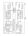
- FIG. 1 and FIG. 2 illustrate various embodiments of communication systems, 100 , and 200 , respectively.
- this embodiment of a communication system 100 is a communication channel 199 that communicatively couples a communication device 110 (including a transmitter 112 having an encoder 114 and including a receiver 116 having a decoder 118 ) situated at one end of the communication channel 199 to another communication device 120 (including a transmitter 126 having an encoder 128 and including a receiver 122 having a decoder 124 ) at the other end of the communication channel 199 .
- either of the communication devices 110 and 120 may only include a transmitter or a receiver.
- the communication channel 199 may be implemented (e.g., a satellite communication channel 130 using satellite dishes 132 and 134 , a wireless communication channel 140 using towers 142 and 144 and/or local antennae 152 and 154 , a wired communication channel 150 , and/or a fiber-optic communication channel 160 using electrical to optical (E/O) interface 162 and optical to electrical (O/E) interface 164 )).
- a satellite communication channel 130 using satellite dishes 132 and 134 e.g., a satellite communication channel 130 using satellite dishes 132 and 134 , a wireless communication channel 140 using towers 142 and 144 and/or local antennae 152 and 154 , a wired communication channel 150 , and/or a fiber-optic communication channel 160 using electrical to optical (E/O) interface 162 and optical to electrical (O/E) interface 164 )
- E/O electrical to optical
- O/E optical to electrical
- communication devices 110 and/or 120 may be stationary or mobile without departing from the scope and spirit of the invention.
- either one or both of the communication devices 110 and 120 may be implemented in a fixed location or may be a mobile communication device with capability to associate with and/or communicate with more than one network access point (e.g., different respective access points (APs) in the context of a mobile communication system including one or more wireless local area networks (WLANs), different respective satellites in the context of a mobile communication system including one or more satellite, or generally, different respective network access points in the context of a mobile communication system including one or more network access points by which communications may be effectuated with communication devices 110 and/or 120 .
- APs access points
- WLANs wireless local area networks
- satellites in the context of a mobile communication system including one or more satellite
- network access points by which communications may be effectuated with communication devices 110 and/or 120 .
- error correction and channel coding schemes are often employed.
- these error correction and channel coding schemes involve the use of an encoder at the transmitter end of the communication channel 199 and a decoder at the receiver end of the communication channel 199 .
- ECC codes described can be employed within any such desired communication system (e.g., including those variations described with respect to FIG. 1 ), any information storage device (e.g., hard disk drives (HDDs), network information storage devices and/or servers, etc.) or any application in which information encoding and/or decoding is desired.
- any information storage device e.g., hard disk drives (HDDs), network information storage devices and/or servers, etc.
- any application in which information encoding and/or decoding is desired.
- video data encoding may generally be viewed as being performed at a transmitting end of the communication channel 199
- video data decoding may generally be viewed as being performed at a receiving end of the communication channel 199 .
- the communication device 110 may include only video data encoding capability
- the communication device 120 may include only video data decoding capability, or vice versa (e.g., in a uni-directional communication embodiment such as in accordance with a video broadcast embodiment).
- information bits 201 are provided to a transmitter 297 that is operable to perform encoding of these information bits 201 using an encoder and symbol mapper 220 (which may be viewed as being distinct functional blocks 222 and 224 , respectively) thereby generating a sequence of discrete-valued modulation symbols 203 that is provided to a transmit driver 230 that uses a DAC (Digital to Analog Converter) 232 to generate a continuous-time transmit signal 204 and a transmit filter 234 to generate a filtered, continuous-time transmit signal 205 that substantially comports with the communication channel 299 .
- DAC Digital to Analog Converter
- continuous-time receive signal 206 is provided to an AFE (Analog Front End) 260 that includes a receive filter 262 (that generates a filtered, continuous-time receive signal 207 ) and an ADC (Analog to Digital Converter) 264 (that generates discrete-time receive signals 208 ).
- a metric generator 270 calculates metrics 209 (e.g., on either a symbol and/or bit basis) that are employed by a decoder 280 to make best estimates of the discrete-valued modulation symbols and information bits encoded therein 210 .
- this diagram shows a processing module 280 a as including the encoder and symbol mapper 220 and all associated, corresponding components therein, and a processing module 280 b is shown as including the metric generator 270 and the decoder 280 and all associated, corresponding components therein.
- processing modules 280 a and 280 b may be respective integrated circuits.
- other boundaries and groupings may alternatively be performed without departing from the scope and spirit of the invention.
- all components within the transmitter 297 may be included within a first processing module or integrated circuit, and all components within the receiver 298 may be included within a second processing module or integrated circuit.
- any other combination of components within each of the transmitter 297 and the receiver 298 may be made in other embodiments.
- such a communication system 200 may be employed for the communication of video data is communicated from one location, or subsystem, to another (e.g., from transmitter 297 to the receiver 298 via the communication channel 299 ).
- any of a number of different types of communication systems may employ various aspects, embodiments, and/or their equivalents, of the invention.
- Certain communication systems may include communication links of varying types (e.g., wireless, wired, optical, etc.). Any such communication system that includes at least one wireless communication link therein can operate in accordance with any one or more of the various aspects, embodiments, and/or their equivalents, of the invention.
- Various aspects, embodiments, and/or their equivalents, of the invention may be applied to a wireless communication link that is line of sight (LOS) and in which at least one of a transmitter wireless communication device and a receiver wireless communication device includes more than one antenna for receiving and transmitting signals.
- LOS line of sight
- FIG. 3 is a diagram illustrating an embodiment 300 of a wireless communication device that includes the host device 18 - 32 and an associated radio 60 .
- the radio 60 is a built-in component.
- the radio 60 may be built-in or an externally coupled component.
- the components are typically housed in a single structure.
- the host device 18 - 32 includes a processing module 50 , memory 52 , radio interface 54 , input interface 58 and output interface 56 .
- the processing module 50 and memory 52 execute the corresponding instructions that are typically done by the host device. For example, for a cellular telephone host device, the processing module 50 performs the corresponding communication functions in accordance with a particular cellular telephone standard.
- the radio interface 54 allows data to be received from and sent to the radio 60 .
- the radio interface 54 For data received from the radio 60 (e.g., inbound data), the radio interface 54 provides the data to the processing module 50 for further processing and/or routing to the output interface 56 .
- the output interface 56 provides connectivity to an output display device such as a display, monitor, speakers, etc. such that the received data may be displayed.
- the radio interface 54 also provides data from the processing module 50 to the radio 60 .
- the processing module 50 may receive the outbound data from an input device such as a keyboard, keypad, microphone, etc. via the input interface 58 or generate the data itself.
- the processing module 50 may perform a corresponding host function on the data and/or route it to the radio 60 via the radio interface 54 .
- Radio 60 includes a host interface 62 , a baseband processing module 64 , memory 66 , a plurality of radio frequency (RF) transmitters 68 - 72 , a transmit/receive (T/R) module 74 , a plurality of antennae 82 - 86 , a plurality of RF receivers 76 - 80 , and a local oscillation module (LO) 100 .
- RF radio frequency
- T/R transmit/receive
- LO local oscillation module
- each respective antennae of the wireless communication device may be driven from the same LO module 100 to compensate for, minimize, and/or reduce any phase noise generated in the respective antennae of the wireless communication device.
- the baseband processing module 64 execute digital receiver functions and digital transmitter functions, respectively.
- the digital receiver functions include, but are not limited to, digital intermediate frequency to baseband conversion, demodulation, constellation demapping, decoding, de-interleaving, fast Fourier transform, cyclic prefix removal, space and time decoding, and/or descrambling.
- the digital transmitter functions include, but are not limited to, scrambling, encoding, interleaving, constellation mapping, modulation, inverse fast Fourier transform, cyclic prefix addition, space and time encoding, and/or digital baseband to IF conversion.
- the baseband processing modules 64 may be implemented using one or more processing devices.
- Such a processing device may be a microprocessor, micro-controller, digital signal processor, microcomputer, central processing unit, field programmable gate array, programmable logic device, state machine, logic circuitry, analog circuitry, digital circuitry, and/or any device that manipulates signals (analog and/or digital) based on operational instructions.
- the memory 66 may be a single memory device or a plurality of memory devices.
- Such a memory device may be a read-only memory, random access memory, volatile memory, non-volatile memory, static memory, dynamic memory, flash memory, and/or any device that stores digital information.
- the processing module 64 implements one or more of its functions via a state machine, analog circuitry, digital circuitry, and/or logic circuitry
- the memory storing the corresponding operational instructions is embedded with the circuitry comprising the state machine, analog circuitry, digital circuitry, and/or logic circuitry.
- the radio 60 receives outbound data 88 from the host device via the host interface 62 .
- the baseband processing module 64 receives the outbound data 88 and, based on a mode selection signal 102 , produces one or more outbound symbol streams 90 .
- the baseband processing module 64 receives the outbound data 88 and, based on a mode selection signal 102 , produces one or more outbound symbol streams 90 .
- a mode selection signal 102 will indicate a particular mode or operation (e.g., indicate a frequency band of 2.4 GHz or 5 GHz, a channel bandwidth of 20 or 22 MHz (e.g., channels of 20 or 22 MHz width)) and a maximum bit rate of 54 megabits-per-second.
- the channel bandwidth may extend up to 1.28 GHz or wider with supported maximum bit rates extending to 1 gigabit-per-second or greater.
- the mode selection signal will further indicate a particular rate ranging from 1 megabit-per-second to 54 megabits-per-second.
- the mode selection signal will indicate a particular type of modulation, which includes, but is not limited to, Barker Code Modulation, BPSK, QPSK, CCK, 16 QAM and/or 64 QAM.
- a code rate may be supplied as well as number of coded bits per subcarrier (NBPSC), coded bits per OFDM symbol (NCBPS), data bits per OFDM symbol (NDBPS).
- the baseband processing module 64 based on the mode selection signal 102 produces the one or more outbound symbol streams 90 from the outbound data 88 . For example, if the mode selection signal 102 indicates that a single transmit antenna is being utilized for the particular mode that has been selected, the baseband processing module 64 will produce a single outbound symbol stream 90 . Alternatively, if the mode select signal indicates 2, 3 or 4 antennae, the baseband processing module 64 will produce 2, 3 or 4 outbound symbol streams 90 corresponding to the number of antennae from the outbound data 88 .
- a corresponding number of the RF transmitters 68 - 72 will be enabled to convert the outbound symbol streams 90 into outbound RF signals 92 .
- the transmit/receive module 74 receives the outbound RF signals 92 and provides each outbound RF signal to a corresponding antenna 82 - 86 .
- the transmit/receive module 74 receives one or more inbound RF signals via the antennae 82 - 86 .
- the T/R module 74 provides the inbound RF signals 94 to one or more RF receivers 76 - 80 .
- the RF receiver 76 - 80 converts the inbound RF signals 94 into a corresponding number of inbound symbol streams 96 .
- the number of inbound symbol streams 96 will correspond to the particular mode in which the data was received (e.g., and, in some embodiments, a particular a mode may be select for operation).
- the baseband processing module 64 receives the inbound symbol streams 96 and converts them into inbound data 98 , which is provided to the host device 18 - 32 via the host interface 62 .
- radio 60 it includes a transmitter and a receiver.
- the transmitter may include a MAC module, a PLCP module, and a PMD module.
- the Medium Access Control (MAC) module which may be implemented with the processing module 64 , is operably coupled to convert a MAC Service Data Unit (MSDU) into a MAC Protocol Data Unit (MPDU) in accordance with a WLAN protocol.
- the Physical Layer Convergence Procedure (PLCP) Module which may be implemented in the processing module 64 , is operably coupled to convert the MPDU into a PLCP Protocol Data Unit (PPDU) in accordance with the WLAN protocol.
- MAC Medium Access Control
- PLCP Physical Layer Convergence Procedure
- the Physical Medium Dependent (PMD) module is operably coupled to convert the PPDU into a plurality of radio frequency (RF) signals in accordance with one of a plurality of operating modes of the WLAN protocol, wherein the plurality of operating modes includes multiple input and multiple output combinations.
- RF radio frequency
- An embodiment of the Physical Medium Dependent (PMD) module includes an error protection module, a demultiplexing module, and a plurality of direction conversion modules.
- the error protection module which may be implemented in the processing module 64 , is operably coupled to restructure a PPDU (PLCP (Physical Layer Convergence Procedure) Protocol Data Unit) to reduce transmission errors producing error protected data.
- the demultiplexing module is operably coupled to divide the error protected data into a plurality of error protected data streams.
- the plurality of direct conversion modules is operably coupled to convert the plurality of error protected data streams into a plurality of radio frequency (RF) signals.
- RF radio frequency
- the wireless communication device of FIG. 3 may be implemented using one or more integrated circuits.
- the host device may be implemented on one integrated circuit
- the baseband processing module 64 and memory 66 may be implemented on a second integrated circuit
- the remaining components of the radio 60 less the antennae 82 - 86 , may be implemented on a third integrated circuit.
- the radio 60 may be implemented on a single integrated circuit.
- the processing module 50 of the host device and the baseband processing module 64 may be a common processing device implemented on a single integrated circuit.
- the memory 52 and memory 66 may be implemented on a single integrated circuit and/or on the same integrated circuit as the common processing modules of processing module 50 and the baseband processing module 64 .
- FIG. 4 illustrates an embodiment 400 of an M ⁇ N multiple-input-multiple-output (MIMO) communication system.
- An M ⁇ N MIMO communication system may be viewed as including at least one transmitter wireless communication device having M transmitters (e.g., M antennae) and at least one receiver wireless communication device having N receivers (e.g., N antennae).
- M transmitters e.g., M antennae
- N receivers e.g., N antennae
- the different paths are generated by reflections from the environment, (e.g., ground, walls).
- Communication systems may be implemented using any of a variety of communication media, technologies, etc. such as with reference to FIG. 1 , and if at least one such communication link therein is a wireless line of sight (LOS) communication link (e.g., in a microwave communication system), separation (of the respective paths between transmitter antennae and receiver antennae) is achieved geometrically.
- LOS line of sight
- FIG. 5 illustrates an embodiment 500 of a 2 ⁇ 2 MIMO communication system and the corresponding channel matrix.
- any such MIMO communication system may include any desired number of transmitter antennae and any desired number of receiver antennae (and each of the transmitter and receiver wireless communication devices may have different respective numbers of antennae).
- the channel matrix can be expressed as follows:
- the condition number with respect to inversion represents the ratio of the largest singular value of H to the smallest. Large condition numbers indicate a nearly singular matrix.
- FIG. 7 illustrates an embodiment 700 of a generalized model associated with optimal separation between antennae within respective transmitter and receiver wireless communication devices.
- the optimal distance depends on the carrier wave length ⁇ , and the physical distance d link between the antennae.
- an optimal d t and d r values can be calculated.
- An example of a generalized model can is shown pictorially in FIG. 7 .
- a novel approach may be referred to as Geometrical Open Loop MIMO approach, as there is no feedback from the receiver to the transmitter regarding the Geometrical channel transfer function.
- FIG. 9 illustrates an embodiment 900 showing geometrical beamforming, respective 2 independent single-output-single-input (SISO) channels, and channel capacity of an M ⁇ N MIMO communication system.
- SISO single-output-single-input
- H using Singular Value Decomposition (SVD)
- These respective channel matrices may be viewed as corresponding to a singular value decomposition (SVD) of the line of sight (LOS) multiple-input-multiple-output (MIMO) communication channel into respective independent streams at the transmitter communication device.
- SMD singular value decomposition
- LOS line of sight
- MIMO multiple-input-multiple-output
- the transmitted signal can be multiplied by V in the transmitter wireless communication device and the received signal then multiplied by U H in the receiver wireless communication device (or the receiver wireless communication device can perform Zero Forcing, such as in accordance with performing zero forcing equalization (ZFE) on the signal to effectuate the increase in information carrying capacity of the signal).
- ZFE zero forcing equalization
- the first antenna will transmit the sum of the transmitted original signals and second antenna will transmit the difference of the two signals.
- Geometrical Beam forming in the transmitter wireless communication device Such a format of a matrix may be referred as Geometrical Beam forming in the transmitter wireless communication device.
- These multiplications parallelize the MIMO channel into 2 independent SISO channels with gains of ⁇ 1 and ⁇ 2, as shown in the diagram.
- the value of ⁇ corresponds to the ratio of the optimal antenna spacing (d opt ) and the actual antenna spacing (d).
- the capacity of the communication of the channel can be then calculated according to the equation depicted in the middle of the diagram.
- At least one difference between closed loop and open loop schemes is that, in the closed loop approach, the communication channel is decomposed into independent streams at the transmitter, and in each one, the maximum number of bits that can be transmitted reliably given a power constraint are transmitted.
- open loop schemes no such decomposition exists at the transmitter, such that, when trying to perform the decomposition at the receiver wireless communication device (e.g., using a zero forcing equalizer to perform zero forcing equalization (ZFE)), then a severe noise enhancement may occur, if the optimal antenna spacing cannot be guaranteed.
- ZFE zero forcing equalizer to perform zero forcing equalization
- FIG. 10 illustrates an embodiment 1000 showing performance improvement as provided by geometric closed loop operation for line of sight (LOS) MIMO.
- LOS line of sight
- a first approach may be referred as Static Geometrical Closed Loop MIMO architecture.
- Static Geometrical Closed Loop MIMO architecture upon setting the transmitted and received antennae, measuring the geometrical setup and then calculating the optimal values for V and U H for use in the transmitter and receiver wireless communication devices.
- the second approach may be referred to as Dynamic Geometrical Closed Loop MIMO architecture.
- the receiver wireless communication device will dynamically and continuously measure the channel matrix and then will update the transmitter with the optimal values to use (e.g., the optimal values of V to transmit the data with).
- a LOS MIMO communication channel e.g., a microwave channel
- such a communication channel is mostly composed of a relatively few number of rays (e.g., 2-3 rays, such as at least one LOS channel and at least one non-LOS channel—such as characterized as a Rummler channel).
- such a communication channel typically doesn't change very rapidly, and such variations can generally be easily tracked at the receiver wireless communication device, and a relatively low bandwidth feedback channel between the receiver and the transmitter wireless communication device may be employed to effectuate such feedback of information.
- FIG. 11 and FIG. 12 illustrate various embodiments of methods 1100 and 1200 , respectively, for operating one or more communication devices.
- the method 1100 begins by operating a first plurality of antennae of a communication device (e.g., receiver wireless communication device) to receive a signal transmitted from a second plurality of antennae of at least one additional communication device (e.g., transmitter wireless communication device) via a line of sight (LOS) multiple-input-multiple-output (MIMO) communication channel between the communication device and the at least one additional communication device, as shown in a block 1110 .
- a communication device e.g., receiver wireless communication device
- at least one additional communication device e.g., transmitter wireless communication device
- MIMO multiple-input-multiple-output
- the method 1100 then operates by processing the signal (e.g., within receiver wireless communication device) using one of a plurality of channel matrices, corresponding to a singular value decomposition (SVD) of the LOS MIMO communication channel into a plurality of independent streams at the at least one additional communication device, to effectuate an increase in information carrying capacity of the signal, as shown in a block 1120 .
- a singular value decomposition SVD
- the method 1200 begins by processing a signal (e.g., within a transmitter wireless communication device) using one of the channel matrices, corresponding to the SVD of a LOS MIMO communication channel into independent stream at the transmitter wireless communication device, as shown in a block 1210 .
- the method 1200 continues by transmitting the processed signal from the transmitter wireless communication device (having M antennae) to a receiver wireless communication device (having N antennae), as shown in a block 1220 .
- the method 1200 then operates by receiving the processed signal from the LOS MIMO communication channel, as shown in a block 1230 .
- the method 1200 continues by processing the signal (e.g., within receiver wireless communication device) using another one of the channel matrices, corresponding to the SVD of a LOS MIMO communication channel into independent stream at the transmitter wireless communication device (processing in transmitter wireless communication device and receiver wireless communication device with respective channel matrices to effectuate an increase in information carrying capacity of the signal), as shown in a block 1240 .
- various communication systems may include wireless communications effectuated in accordance with at least one LOS MIMO communication channel.
- the antenna spacing of such wireless communication devices may not be perfectly optimal to effectuate the maximum data throughput within the system.
- operating in accordance with various aspects, embodiments, and/or their equivalents, of the invention can recover much, if not all, of the lost performance or degradation resulting from imperfectly spaced antennae.
- phase noises may be handled appropriately in any one of a number or combination of ways.
- the respective antennae within a given communication device may all be driven from a common or singular local oscillator (LO).
- LO local oscillator
- a receiver device may perform channel estimation, among other channel monitoring activities, and provide such information to the transmitter so that the transmitter may compensate for any tracked phase noise (including differential phase noise) between respective antennae in a given device. It is also noted that such channel estimation operations may be performed cooperatively between a receiver device and the transmitter device.
- the data throughput which may be achieved within the system can approach or converge to the Shannon limit channel capacity (e.g., in bits per second per Hz).
- the Shannon limit channel capacity e.g., in bits per second per Hz.
- phase noise may be addressed in one embodiment by continuously, or periodically, updating the respective channel matrices U and V based upon such phase noise.
- a same or singular local oscillator may be employed to drive each of the respective antennae within a given device. Either of these particular means to address phase noise may be employed individually, or they may be employed cooperatively within a given embodiment.
- such a processor, circuitry, and/or a processing module, etc. can perform such processing to generate signals for communication with other communication devices in accordance with various aspects of the invention, and/or any other operations and functions as described herein, etc. or their respective equivalents.
- processing is performed cooperatively by a first processor, circuitry, and/or a processing module, etc. in a first device, and a second first processor, circuitry, and/or a processing module, etc. within a second device.
- such processing is performed wholly by a processor, circuitry, and/or a processing module, etc. within a singular communication device.
- the terms “substantially” and “approximately” provides an industry-accepted tolerance for its corresponding term and/or relativity between items. Such an industry-accepted tolerance ranges from less than one percent to fifty percent and corresponds to, but is not limited to, component values, integrated circuit process variations, temperature variations, rise and fall times, and/or thermal noise. Such relativity between items ranges from a difference of a few percent to magnitude differences.
- the term(s) “operably coupled to”, “coupled to”, and/or “coupling” includes direct coupling between items and/or indirect coupling between items via an intervening item (e.g., an item includes, but is not limited to, a component, an element, a circuit, and/or a module) where, for indirect coupling, the intervening item does not modify the information of a signal but may adjust its current level, voltage level, and/or power level.
- inferred coupling i.e., where one element is coupled to another element by inference
- the term “operable to” or “operably coupled to” indicates that an item includes one or more of power connections, input(s), output(s), etc., to perform, when activated, one or more its corresponding functions and may further include inferred coupling to one or more other items.
- the term “associated with”, includes direct and/or indirect coupling of separate items and/or one item being embedded within another item.
- the term “compares favorably”, indicates that a comparison between two or more items, signals, etc., provides a desired relationship. For example, when the desired relationship is that signal 1 has a greater magnitude than signal 2 , a favorable comparison may be achieved when the magnitude of signal 1 is greater than that of signal 2 or when the magnitude of signal 2 is less than that of signal 1 .
- processing module may be a single processing device or a plurality of processing devices.
- processing device may be a microprocessor, micro-controller, digital signal processor, microcomputer, central processing unit, field programmable gate array, programmable logic device, state machine, logic circuitry, analog circuitry, digital circuitry, and/or any device that manipulates signals (analog and/or digital) based on hard coding of the circuitry and/or operational instructions.
- the processing module, module, processing circuit, and/or processing unit may have an associated memory and/or an integrated memory element, which may be a single memory device, a plurality of memory devices, and/or embedded circuitry of the processing module, module, processing circuit, and/or processing unit.
- a memory device may be a read-only memory (ROM), random access memory (RAM), volatile memory, non-volatile memory, static memory, dynamic memory, flash memory, cache memory, and/or any device that stores digital information.
- processing module, module, processing circuit, and/or processing unit includes more than one processing device, the processing devices may be centrally located (e.g., directly coupled together via a wired and/or wireless bus structure) or may be distributedly located (e.g., cloud computing via indirect coupling via a local area network and/or a wide area network). Further note that if the processing module, module, processing circuit, and/or processing unit implements one or more of its functions via a state machine, analog circuitry, digital circuitry, and/or logic circuitry, the memory and/or memory element storing the corresponding operational instructions may be embedded within, or external to, the circuitry comprising the state machine, analog circuitry, digital circuitry, and/or logic circuitry.
- the memory element may store, and the processing module, module, processing circuit, and/or processing unit executes, hard coded and/or operational instructions corresponding to at least some of the steps and/or functions illustrated in one or more of the Figures.
- Such a memory device or memory element can be included in an article of manufacture.
- the present invention may have also been described, at least in part, in terms of one or more embodiments.
- An embodiment of the present invention is used herein to illustrate the present invention, an aspect thereof, a feature thereof, a concept thereof, and/or an example thereof.
- a physical embodiment of an apparatus, an article of manufacture, a machine, and/or of a process that embodies the present invention may include one or more of the aspects, features, concepts, examples, etc. described with reference to one or more of the embodiments discussed herein.
- the embodiments may incorporate the same or similarly named functions, steps, modules, etc. that may use the same or different reference numbers and, as such, the functions, steps, modules, etc. may be the same or similar functions, steps, modules, etc. or different ones.
- signals to, from, and/or between elements in a figure of any of the figures presented herein may be analog or digital, continuous time or discrete time, and single-ended or differential.
- signals to, from, and/or between elements in a figure of any of the figures presented herein may be analog or digital, continuous time or discrete time, and single-ended or differential.
- a signal path is shown as a single-ended path, it also represents a differential signal path.
- a signal path is shown as a differential path, it also represents a single-ended signal path.
- module is used in the description of the various embodiments of the present invention.
- a module includes a functional block that is implemented via hardware to perform one or module functions such as the processing of one or more input signals to produce one or more output signals.
- the hardware that implements the module may itself operate in conjunction software, and/or firmware.
- a module may contain one or more sub-modules that themselves are modules.
Landscapes
- Engineering & Computer Science (AREA)
- Computer Networks & Wireless Communication (AREA)
- Signal Processing (AREA)
- Physics & Mathematics (AREA)
- Mathematical Physics (AREA)
- Radio Transmission System (AREA)
- Mobile Radio Communication Systems (AREA)
Abstract
Description
- 1. U.S. Provisional Patent Application Ser. No. 61/647,380, entitled “Geometrical closed loop architecture for line of sight MIMO,”, filed May 15, 2012.
d t d r=(λ×d link)/2
H=UΣV H(V,U[unitary],Σ[diagonal])
Claims (20)
Priority Applications (5)
| Application Number | Priority Date | Filing Date | Title |
|---|---|---|---|
| US13/730,255 US9077407B2 (en) | 2012-05-15 | 2012-12-28 | Geometrical closed loop line of sight (LOS) multiple-input-multiple-output (MIMO) |
| TW102115597A TWI504185B (en) | 2012-05-15 | 2013-05-01 | Geometrical closed loop line of sight (los) multiple-input-multiple-output (mimo) |
| EP13002461.5A EP2665204A1 (en) | 2012-05-15 | 2013-05-08 | Geometrical closed loop line of sight (LOS) multiple-input-multiple-output (MIMO) |
| KR20130055090A KR101480737B1 (en) | 2012-05-15 | 2013-05-15 | Geometrical closed loop line of sight (LOS) multiple-input-multiple-output (MIMO) |
| CN2013101802128A CN103427891A (en) | 2012-05-15 | 2013-05-15 | Geometrical closed loop line of sight (LOS) multiple-input-multiple-output (MIMO) |
Applications Claiming Priority (2)
| Application Number | Priority Date | Filing Date | Title |
|---|---|---|---|
| US201261647380P | 2012-05-15 | 2012-05-15 | |
| US13/730,255 US9077407B2 (en) | 2012-05-15 | 2012-12-28 | Geometrical closed loop line of sight (LOS) multiple-input-multiple-output (MIMO) |
Publications (2)
| Publication Number | Publication Date |
|---|---|
| US20130309976A1 US20130309976A1 (en) | 2013-11-21 |
| US9077407B2 true US9077407B2 (en) | 2015-07-07 |
Family
ID=48366106
Family Applications (1)
| Application Number | Title | Priority Date | Filing Date |
|---|---|---|---|
| US13/730,255 Active 2033-05-17 US9077407B2 (en) | 2012-05-15 | 2012-12-28 | Geometrical closed loop line of sight (LOS) multiple-input-multiple-output (MIMO) |
Country Status (5)
| Country | Link |
|---|---|
| US (1) | US9077407B2 (en) |
| EP (1) | EP2665204A1 (en) |
| KR (1) | KR101480737B1 (en) |
| CN (1) | CN103427891A (en) |
| TW (1) | TWI504185B (en) |
Cited By (12)
| Publication number | Priority date | Publication date | Assignee | Title |
|---|---|---|---|---|
| US9923708B2 (en) | 2012-05-13 | 2018-03-20 | Amir Keyvan Khandani | Full duplex wireless transmission with channel phase-based encryption |
| US9997830B2 (en) | 2012-05-13 | 2018-06-12 | Amir Keyvan Khandani | Antenna system and method for full duplex wireless transmission with channel phase-based encryption |
| US10063364B2 (en) | 2013-11-30 | 2018-08-28 | Amir Keyvan Khandani | Wireless full-duplex system and method using sideband test signals |
| US10177896B2 (en) | 2013-05-13 | 2019-01-08 | Amir Keyvan Khandani | Methods for training of full-duplex wireless systems |
| US10333593B2 (en) | 2016-05-02 | 2019-06-25 | Amir Keyvan Khandani | Systems and methods of antenna design for full-duplex line of sight transmission |
| US10334637B2 (en) | 2014-01-30 | 2019-06-25 | Amir Keyvan Khandani | Adapter and associated method for full-duplex wireless communication |
| US10361889B2 (en) * | 2016-03-17 | 2019-07-23 | Electronics And Telecommunications Research Institute | Wireless communication apparatus for increasing throughput using MIMO in LOS environment and method therefor |
| US10659138B1 (en) | 2018-12-04 | 2020-05-19 | Huawei Technologies Co., Ltd. | System and method for precoding in a line of sight (LOS) multiple-input multiple-output (MIMO) communication system |
| US10700766B2 (en) | 2017-04-19 | 2020-06-30 | Amir Keyvan Khandani | Noise cancelling amplify-and-forward (in-band) relay with self-interference cancellation |
| US11012144B2 (en) | 2018-01-16 | 2021-05-18 | Amir Keyvan Khandani | System and methods for in-band relaying |
| US11057204B2 (en) | 2017-10-04 | 2021-07-06 | Amir Keyvan Khandani | Methods for encrypted data communications |
| US12160293B2 (en) | 2021-01-13 | 2024-12-03 | Electronics And Telecommunications Research Institute | Method and apparatus for initial access in communication system |
Families Citing this family (11)
| Publication number | Priority date | Publication date | Assignee | Title |
|---|---|---|---|---|
| WO2014198286A1 (en) * | 2013-06-10 | 2014-12-18 | Telefonaktiebolaget L M Ericsson (Publ) | Radio link performance prediction |
| WO2014202156A1 (en) * | 2013-06-18 | 2014-12-24 | Telefonaktiebolaget L M Ericsson (Publ) | Leakage cancellation for a multiple-input multiple-output transceiver |
| CN103973347B (en) * | 2014-05-27 | 2017-04-19 | 西安电子科技大学 | Closed loop zero-setting shape-preserving method of satellite communication antenna |
| CN107615676B (en) * | 2015-06-04 | 2020-10-09 | 华为技术有限公司 | Multi-input multi-output transmission method, terminal and base station |
| KR102456841B1 (en) | 2016-01-04 | 2022-10-21 | 한국전자통신연구원 | Method for Enhancing Performance of Multi-Input Multi-Output System on Line-of-Sight |
| JP6996496B2 (en) * | 2016-04-19 | 2022-01-17 | 日本電気株式会社 | LOS-MIMO demodulation device, communication device, LOS-MIMO transmission system, LOS-MIMO demodulation method and program |
| CN108259143B (en) | 2016-12-28 | 2020-02-28 | 电信科学技术研究院 | A reference signal transmission method, transmitter and receiver |
| CN110873825B (en) * | 2018-09-03 | 2024-05-03 | 罗德施瓦兹两合股份有限公司 | Method for determining a faulty DUT antenna and measurement system |
| WO2023068867A1 (en) * | 2021-10-22 | 2023-04-27 | 단국대학교 산학협력단 | Apparatus and method for transmitting data in multi-antenna system |
| US20240396594A1 (en) * | 2021-10-22 | 2024-11-28 | Industry-Academic Cooperation Foundation, Dankook University | Method and apparatus for transmitting reference signal in multi-antenna system |
| US12470266B2 (en) | 2021-11-18 | 2025-11-11 | Qualcomm Incorporated | Method and apparatus for codebook design for closed loop operation |
Citations (2)
| Publication number | Priority date | Publication date | Assignee | Title |
|---|---|---|---|---|
| US20090296846A1 (en) * | 2006-11-17 | 2009-12-03 | Tsuguo Maru | Mimo communication system having deterministic channels and method |
| EP2180623A1 (en) | 2007-08-02 | 2010-04-28 | Nec Corporation | Mimo communication system having deterministic communication path and antenna arrangement method therefor |
Family Cites Families (2)
| Publication number | Priority date | Publication date | Assignee | Title |
|---|---|---|---|---|
| DE3640619C1 (en) * | 1986-11-27 | 1988-05-19 | Duerkopp System Technik Gmbh | Cutting material underlay |
| JP2010109631A (en) * | 2008-10-29 | 2010-05-13 | Kyocera Corp | Wireless communication system, transmission device, and communication signal transmission method |
-
2012
- 2012-12-28 US US13/730,255 patent/US9077407B2/en active Active
-
2013
- 2013-05-01 TW TW102115597A patent/TWI504185B/en not_active IP Right Cessation
- 2013-05-08 EP EP13002461.5A patent/EP2665204A1/en not_active Withdrawn
- 2013-05-15 KR KR20130055090A patent/KR101480737B1/en not_active Expired - Fee Related
- 2013-05-15 CN CN2013101802128A patent/CN103427891A/en active Pending
Patent Citations (3)
| Publication number | Priority date | Publication date | Assignee | Title |
|---|---|---|---|---|
| US20090296846A1 (en) * | 2006-11-17 | 2009-12-03 | Tsuguo Maru | Mimo communication system having deterministic channels and method |
| EP2180623A1 (en) | 2007-08-02 | 2010-04-28 | Nec Corporation | Mimo communication system having deterministic communication path and antenna arrangement method therefor |
| US8571125B2 (en) * | 2007-08-02 | 2013-10-29 | Nec Corporation | MIMO communication system having deterministic channels and antenna arrangement method therfor |
Non-Patent Citations (6)
| Title |
|---|
| Alcatel-Lucent Shanghai Bell, et al.; An Over-the-Air-Calibration Scheme for ZF based SU/MU-MIMO; 3GPP TSG RAN WG1 Meeting #57bis; Jun. 29-Jul. 30 2009; pp. 1-10. |
| Daneshrad, et al.; Phase noise suppression in MIMO OFDM systems with incoherent phase noise; IEEE Military Communications Conference; 2011 MILCOM; Nov. 7, 2011; pp. 42-44. |
| European Patent Office; European Search Report; EP Application No. 13002461.5; Sep. 4, 2013; 4 pgs. |
| Lebrun, et al; MIMO transmission over a time-varying channel using SVD; Global Telecommunications Conference; GLOBECOM '02; Nov. 17-21, 2002; pp. 414-418; vol. 1. |
| Lebrun, et al; MIMO transmission over a time-varying channel using SVD; IEEE Transactions on Wireless Communications; Mar. 2005; pp. 757-764; vol. 4, Iss 2. |
| Yi, et al.; MIMO transceiver design using geometric mean decomposition; IEEE Information Theory Workshop; Oct. 24-29, 2004; pp. 193-197. |
Cited By (26)
| Publication number | Priority date | Publication date | Assignee | Title |
|---|---|---|---|---|
| US9923708B2 (en) | 2012-05-13 | 2018-03-20 | Amir Keyvan Khandani | Full duplex wireless transmission with channel phase-based encryption |
| US10742388B2 (en) | 2012-05-13 | 2020-08-11 | Amir Keyvan Khandani | Full duplex wireless transmission with self-interference cancellation |
| US10211965B2 (en) | 2012-05-13 | 2019-02-19 | Amir Keyvan Khandani | Full duplex wireless transmission with channel phase-based encryption |
| US11303424B2 (en) | 2012-05-13 | 2022-04-12 | Amir Keyvan Khandani | Full duplex wireless transmission with self-interference cancellation |
| US11757604B2 (en) | 2012-05-13 | 2023-09-12 | Amir Keyvan Khandani | Distributed collaborative signaling in full duplex wireless transceivers |
| US9997830B2 (en) | 2012-05-13 | 2018-06-12 | Amir Keyvan Khandani | Antenna system and method for full duplex wireless transmission with channel phase-based encryption |
| US10547436B2 (en) | 2012-05-13 | 2020-01-28 | Amir Keyvan Khandani | Distributed collaborative signaling in full duplex wireless transceivers |
| US11757606B2 (en) | 2012-05-13 | 2023-09-12 | Amir Keyvan Khandani | Full duplex wireless transmission with self-interference cancellation |
| US10177896B2 (en) | 2013-05-13 | 2019-01-08 | Amir Keyvan Khandani | Methods for training of full-duplex wireless systems |
| US10063364B2 (en) | 2013-11-30 | 2018-08-28 | Amir Keyvan Khandani | Wireless full-duplex system and method using sideband test signals |
| US10374781B2 (en) | 2013-11-30 | 2019-08-06 | Amir Keyvan Khandani | Wireless full-duplex system and method using sideband test signals |
| US10334637B2 (en) | 2014-01-30 | 2019-06-25 | Amir Keyvan Khandani | Adapter and associated method for full-duplex wireless communication |
| US10601569B2 (en) | 2016-02-12 | 2020-03-24 | Amir Keyvan Khandani | Methods for training of full-duplex wireless systems |
| US11515992B2 (en) | 2016-02-12 | 2022-11-29 | Amir Keyvan Khandani | Methods for training of full-duplex wireless systems |
| US10361889B2 (en) * | 2016-03-17 | 2019-07-23 | Electronics And Telecommunications Research Institute | Wireless communication apparatus for increasing throughput using MIMO in LOS environment and method therefor |
| US11283494B2 (en) | 2016-05-02 | 2022-03-22 | Amir Keyvan Khandani | Instantaneous beamforming exploiting user physical signatures |
| US10778295B2 (en) | 2016-05-02 | 2020-09-15 | Amir Keyvan Khandani | Instantaneous beamforming exploiting user physical signatures |
| US10333593B2 (en) | 2016-05-02 | 2019-06-25 | Amir Keyvan Khandani | Systems and methods of antenna design for full-duplex line of sight transmission |
| US10700766B2 (en) | 2017-04-19 | 2020-06-30 | Amir Keyvan Khandani | Noise cancelling amplify-and-forward (in-band) relay with self-interference cancellation |
| US11265074B2 (en) | 2017-04-19 | 2022-03-01 | Amir Keyvan Khandani | Noise cancelling amplify-and-forward (in-band) relay with self-interference cancellation |
| US11212089B2 (en) | 2017-10-04 | 2021-12-28 | Amir Keyvan Khandani | Methods for secure data storage |
| US11146395B2 (en) | 2017-10-04 | 2021-10-12 | Amir Keyvan Khandani | Methods for secure authentication |
| US11057204B2 (en) | 2017-10-04 | 2021-07-06 | Amir Keyvan Khandani | Methods for encrypted data communications |
| US11012144B2 (en) | 2018-01-16 | 2021-05-18 | Amir Keyvan Khandani | System and methods for in-band relaying |
| US10659138B1 (en) | 2018-12-04 | 2020-05-19 | Huawei Technologies Co., Ltd. | System and method for precoding in a line of sight (LOS) multiple-input multiple-output (MIMO) communication system |
| US12160293B2 (en) | 2021-01-13 | 2024-12-03 | Electronics And Telecommunications Research Institute | Method and apparatus for initial access in communication system |
Also Published As
| Publication number | Publication date |
|---|---|
| EP2665204A1 (en) | 2013-11-20 |
| TWI504185B (en) | 2015-10-11 |
| KR20130127952A (en) | 2013-11-25 |
| KR101480737B1 (en) | 2015-01-09 |
| US20130309976A1 (en) | 2013-11-21 |
| TW201347448A (en) | 2013-11-16 |
| CN103427891A (en) | 2013-12-04 |
Similar Documents
| Publication | Publication Date | Title |
|---|---|---|
| US9077407B2 (en) | Geometrical closed loop line of sight (LOS) multiple-input-multiple-output (MIMO) | |
| US11342969B2 (en) | Simplified detection for spatial modulation and space-time block coding with antenna selection | |
| JP5615976B2 (en) | Channel feedback method and communication station | |
| US7729439B2 (en) | Calibration correction for implicit beamforming in a wireless MIMO communication system | |
| US7769082B2 (en) | Frequency domain equalizer for single antenna radio | |
| US8774725B1 (en) | Calibration correction for implicit beamforming in MIMO systems | |
| US20080159424A1 (en) | Angle estimation for space-time block code (STBC) modulated signal | |
| US20080192811A1 (en) | Beamforming methods and apparatus | |
| CN108234072A (en) | For carrying out the decoded method and apparatus of sub-block to data-signal | |
| EP3525369B1 (en) | Transmission method | |
| US8077805B1 (en) | MIMO equalizer method and apparatus | |
| EP2962413B1 (en) | A method and apparatus for cancellating interference in a wireless communication system | |
| EP2930866B1 (en) | Method, apparatus, and computer program for an optical communication system | |
| US10425182B2 (en) | Inter-band distortion and interference mitigation within communication systems | |
| Ishikawa et al. | Single-and multiple-RF aided non-coherent generalized spatial modulation | |
| HK1187164A (en) | Geometrical closed loop line of sight (los) multiple-input-multiple-output (mimo) | |
| US11294674B2 (en) | Devices and methods for parallelized recursive block decoding | |
| Jiang et al. | Practical analysis of codebook design and frequency offset estimation for virtual‐multiple‐input–multiple‐output systems | |
| HK1119502B (en) | A radio frequency (rf) receiver and its operating method | |
| HK1184604A (en) | Constructing very high throughput signal (vht-sig) fields for reduced peak-to-average power ratio (papr) | |
| HK1184604B (en) | Constructing very high throughput signal (vht-sig) fields for reduced peak-to-average power ratio (papr) |
Legal Events
| Date | Code | Title | Description |
|---|---|---|---|
| AS | Assignment |
Owner name: BROADCOM CORPORATION, CALIFORNIA Free format text: ASSIGNMENT OF ASSIGNORS INTEREST;ASSIGNORS:KOREN, SHAY;EISENBERG, YOAV;TSUR, EITAN;SIGNING DATES FROM 20121202 TO 20130118;REEL/FRAME:029654/0640 |
|
| STCF | Information on status: patent grant |
Free format text: PATENTED CASE |
|
| AS | Assignment |
Owner name: BANK OF AMERICA, N.A., AS COLLATERAL AGENT, NORTH CAROLINA Free format text: PATENT SECURITY AGREEMENT;ASSIGNOR:BROADCOM CORPORATION;REEL/FRAME:037806/0001 Effective date: 20160201 Owner name: BANK OF AMERICA, N.A., AS COLLATERAL AGENT, NORTH Free format text: PATENT SECURITY AGREEMENT;ASSIGNOR:BROADCOM CORPORATION;REEL/FRAME:037806/0001 Effective date: 20160201 |
|
| AS | Assignment |
Owner name: BROADCOM CORPORATION, CALIFORNIA Free format text: TERMINATION AND RELEASE OF SECURITY INTEREST IN CERTAIN PATENTS PREVIOUSLY RECORDED AT REEL/FRAME (037806/0001);ASSIGNOR:BANK OF AMERICA, N.A., AS ADMINISTRATIVE AND COLLATERAL AGENT;REEL/FRAME:039235/0401 Effective date: 20160701 |
|
| AS | Assignment |
Owner name: MAXLINEAR ASIA SINGAPORE PRIVATE LIMITED, SINGAPORE Free format text: ASSIGNMENT OF ASSIGNORS INTEREST;ASSIGNOR:BROADCOM CORPORATION;REEL/FRAME:039356/0346 Effective date: 20160701 Owner name: MAXLINEAR ASIA SINGAPORE PRIVATE LIMITED, SINGAPOR Free format text: ASSIGNMENT OF ASSIGNORS INTEREST;ASSIGNOR:BROADCOM CORPORATION;REEL/FRAME:039356/0346 Effective date: 20160701 |
|
| AS | Assignment |
Owner name: BROADCOM CORPORATION, CALIFORNIA Free format text: TERMINATION AND RELEASE OF SECURITY INTEREST IN PATENTS;ASSIGNOR:BANK OF AMERICA, N.A., AS COLLATERAL AGENT;REEL/FRAME:041712/0001 Effective date: 20170119 |
|
| MAFP | Maintenance fee payment |
Free format text: PAYMENT OF MAINTENANCE FEE, 4TH YEAR, LARGE ENTITY (ORIGINAL EVENT CODE: M1551); ENTITY STATUS OF PATENT OWNER: LARGE ENTITY Year of fee payment: 4 |
|
| MAFP | Maintenance fee payment |
Free format text: PAYMENT OF MAINTENANCE FEE, 8TH YEAR, LARGE ENTITY (ORIGINAL EVENT CODE: M1552); ENTITY STATUS OF PATENT OWNER: LARGE ENTITY Year of fee payment: 8 |