US907124A - Manure-spreader. - Google Patents
Manure-spreader. Download PDFInfo
- Publication number
- US907124A US907124A US43100708A US1908431007A US907124A US 907124 A US907124 A US 907124A US 43100708 A US43100708 A US 43100708A US 1908431007 A US1908431007 A US 1908431007A US 907124 A US907124 A US 907124A
- Authority
- US
- United States
- Prior art keywords
- beater
- rake
- spreader
- manure
- sliding
- Prior art date
- Legal status (The legal status is an assumption and is not a legal conclusion. Google has not performed a legal analysis and makes no representation as to the accuracy of the status listed.)
- Expired - Lifetime
Links
- 210000003608 fece Anatomy 0.000 description 15
- 239000010871 livestock manure Substances 0.000 description 15
- 230000000881 depressing effect Effects 0.000 description 2
- 238000010298 pulverizing process Methods 0.000 description 2
- 241000272443 Penelope Species 0.000 description 1
- 241001603151 Philus Species 0.000 description 1
- 208000037656 Respiratory Sounds Diseases 0.000 description 1
- 150000001768 cations Chemical class 0.000 description 1
- 238000010276 construction Methods 0.000 description 1
- 238000000034 method Methods 0.000 description 1
- RSMUVYRMZCOLBH-UHFFFAOYSA-N metsulfuron methyl Chemical compound COC(=O)C1=CC=CC=C1S(=O)(=O)NC(=O)NC1=NC(C)=NC(OC)=N1 RSMUVYRMZCOLBH-UHFFFAOYSA-N 0.000 description 1
- 206010037833 rales Diseases 0.000 description 1
- 239000011435 rock Substances 0.000 description 1
- 241000894007 species Species 0.000 description 1
- NWONKYPBYAMBJT-UHFFFAOYSA-L zinc sulfate Chemical compound [Zn+2].[O-]S([O-])(=O)=O NWONKYPBYAMBJT-UHFFFAOYSA-L 0.000 description 1
Images
Classifications
-
- B—PERFORMING OPERATIONS; TRANSPORTING
- B02—CRUSHING, PULVERISING, OR DISINTEGRATING; PREPARATORY TREATMENT OF GRAIN FOR MILLING
- B02C—CRUSHING, PULVERISING, OR DISINTEGRATING IN GENERAL; MILLING GRAIN
- B02C4/00—Crushing or disintegrating by roller mills
- B02C4/10—Crushing or disintegrating by roller mills with a roller co-operating with a stationary member
- B02C4/18—Crushing or disintegrating by roller mills with a roller co-operating with a stationary member in the form of a bar
- B02C4/22—Crushing or disintegrating by roller mills with a roller co-operating with a stationary member in the form of a bar specially adapted for milling paste-like material, e.g. paint, chocolate, colloids
Definitions
- the object of my present invention is to provide apulv'erizing rakefor vthat class of manure spreaders in which the beater is caable of being moved toward and laway onithe load, and further to provide means whereby a simultaneous movement of lthe beater and rake maybe secured by the use of a single hand ',lever, and' it consists in the construction and arrangement of parts as body and provided with projecting teeth et. l
- sprocket wheel 5 Journaled in suitablebearings air' the rear of the body is sprocket wheel 5, to which rotar;T lmotion is imparted as the manure spreader travels over the ground by means of a sprocket chain connection, 4not herein shown or described as this method of rotating the beater is one in common use, and will. be readily understood by .those conversant with this class of machines.
- Rotated by the 'sprocket wheel 5 is a spur ear' '6 which enga gee pinion 7 on the sha t 8 of the beater.
- the ter shaft 8 is journaled 1n similar beariopposite sides of the spreader in g l I BROWN, p a' citizen of he United States, residing aty ⁇ bell cranksll,
- rake asrepresented in Fig. 2, the body of duplicateoars 9, only one of which is irepresented in the accompanying drawings.
- the bars 9 slide in ways in the frameworkof the spreader and are' connected by links 1f? with pivoted at 12 on the side.-J of the body.
- the bellcranks 11 are connected by links 13 with radial arms 111 carried on a rocking shaft 15 journaled at thev forward end of the body, and provided'with a lever han,- dle 16 in convenient positionto Vbe reached by the driver from the seat 2.
- rocking arms 18 Pivoted upon studs 17 are rocking arms 18 in which are supported a frame 19 carrymg a' rake 20, extending transversely across the body of the spreader andprovided with teeth
- the rocking arm 18 is operatively connected with the sliding bar 9 by means of rocking levers 22 pivoted at 23 upon the side of the body portion, and having theirv opposite ends slotted to engage studs held in 'the arms 18 and the sliding bars 9.
- beaterthen being in its most forward position and serving to retard the backward.
- a manure spreader the combination with a body and a rotatable beater capable of a sliding movement toward and away from the front. of the body, of .a rake capable ol a swinging movement into and out of its operative position, and means for swinging said rake eonjointly with the sliding movement of said beater.
- a manure spreader the combination with a body and a rotatable beater, of means for sliding said beater toward and away. from the front of the body, a rake pivotally supported'above the beater, a lever handle, and operative connections betweenvsaid lever handle and the rake and beater, wherebv the swinging movement of the rake corresponds with the sliding; ⁇ movemen ⁇ r of the beater.
- ott means for slid ing -l beater toward and away from the front oi' the body, a pivoted rake, and means .for depressing said rake as the beater is' '4.
- a 'manure spreader the combination with a body and a beater capable of a Sliding movement toward and away from the front of the body, of a rake pivotally supported, and means forv Sinniltaneonsly sliding said beater and swinging said rake.
- a n'ianure spreader the combination with a body and a rotatable beater, of beater Supports capable of .sliding toward and away from tha'front ot the body, a pivotedrake, means for operatively connecting said rake with said beater supports, and means for sliding said beater supports.
Landscapes
- Engineering & Computer Science (AREA)
- Food Science & Technology (AREA)
- Fertilizing (AREA)
Description
T. BROWN. Y MANIERE SPBEDBB. APPLICATION FILEDIAY 5|, 1908 'Patented Dec. 22, 1908.
Homey THEoPHILUs BEowNjoF WORCESTER, MASSACHUSETTS, ASSIGNOR TO RICHARDSON MAN U- FCTURING COMPANY, OF WORCESTER, MASSACHUSETTS, A CORPORATION OF IYIASSA-` CHUSETTS.
Specification of Letters Patent.
MANURE-SPREADEE.
Patented Dec. 22, 1908.
Application filed May 5, 1908. Serial No. 431,007.
To allie/tom it may concern:
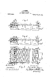
Be 1t known that I, THEoPiiriLUs Worcester, in the county of Worcester and Commonwealth iof Massachusetts, have invented a new and useful Improvement in Manure-.Spreadera of which the following is a speci cation accompanied by drawings forming apart of the same, in which-u F igurel represents aside view ofthe body portion of a manure spreader contain-I ing la beater for distributing the manure and l a pulveri'zing rake mounted in operative posltion above the beater. Fig.4 2 represents the same with the pulverizing rake lowered into inoperative position, and Fig. 3 is a top view ,with they rake lowered in the position shown in Fig-2. I
Similar reference figures refer to similar parts in the diiferent views. l
The object of my present invention is to provide apulv'erizing rakefor vthat class of manure spreaders in which the beater is caable of being moved toward and laway onithe load, and further to provide means whereby a simultaneous movement of lthe beater and rake maybe secured by the use of a single hand ',lever, and' it consists in the construction and arrangement of parts as body and provided with projecting teeth et. l
Journaled in suitablebearings air' the rear of the body is sprocket wheel 5, to which rotar;T lmotion is imparted as the manure spreader travels over the ground by means of a sprocket chain connection, 4not herein shown or described as this method of rotating the beater is one in common use, and will. be readily understood by .those conversant with this class of machines. Rotated by the 'sprocket wheel 5 is a spur ear' '6 which enga gee pinion 7 on the sha t 8 of the beater. The ter shaft 8 is journaled 1n similar beariopposite sides of the spreader in g l I BROWN, p a' citizen of he United States, residing aty `bell cranksll,
rake, asrepresented in Fig. 2, the body of duplicateoars 9, only one of which is irepresented in the accompanying drawings. The bars 9 slide in ways in the frameworkof the spreader and are' connected by links 1f? with pivoted at 12 on the side.-J of the body. 'The bellcranks 11 are connected by links 13 with radial arms 111 carried on a rocking shaft 15 journaled at thev forward end of the body, and provided'with a lever han,- dle 16 in convenient positionto Vbe reached by the driver from the seat 2. Y.
Pivoted upon studs 17 are rocking arms 18 in which are supported a frame 19 carrymg a' rake 20, extending transversely across the body of the spreader andprovided with teeth The rocking arm 18 is operatively connected with the sliding bar 9 by means of rocking levers 22 pivoted at 23 upon the side of the body portion, and having theirv opposite ends slotted to engage studs held in 'the arms 18 and the sliding bars 9. When the sliding bars 9 are moved to the rearward of the spreader in order to carry the pinion 7 into engagement with the drivving gear 6, the arms 18 will be rocked through the cornectinglevers 22 so as to bring the frame 19 into an upright position, with the rake 2O supported above the beater and in proper position to ca use the manure thrown from the load by the revolving beater to become pulverized as it passes through the teeth 21 of the rake. By depressing the lever handle 16, as shown in Fig. 2, the bell cranksll will be rocked to draw the sliding bars 9 forward to bring the pinion 7 out of engagement with the driving gear 6, and to `draw the beater forward inthe body of the spreader. This movement of the handl lever 16 also rocks the arm 18, to lower the frame 19 carrying 'the rake 20 into a horizontal position just above the sides of the body., as shown in Fig. 2, ln the positions of the beater f the spreader is prepared for loading, the
beaterthen being in its most forward position and serving to retard the backward.
' movement in the body of the'loadlof manure..`
When the 'spreader1 is ready for operation, the lever handle 16 isl raised. intoY the posim tion shown in4 Fig. 1, thereby moving the beater rearward yand freeing its teeth from the load of manure so that it may be readily.
rotated and, at the same time, carrying the l pinion 7 into engagement with the driving gear. This rearward movement of the beater simultaneously moves the rale'gt'rom its hori zontal position into the vertical position ehown in Figi: l, in which the teeth 2l: are in proper position to receive the .ini et Ait" the n'ianure as it is thrown by the -oi ing beater teeth.
I am aware that it is not new to equip a manure spreader with al revolving beater, eapable ot' being moved rearward to free its teeth from the load of manure preparatory to the operation et the spreader, and I am also aware that it not new to provide a manure spreader with a pulverizing rake mounted in proper position above the re'- \'olving beater, but I do not herein claim either of these features; the essence or my -present invention consisting` in operatively connecting the rearwardly moving beater with a rockingl rake frame, whereby both the beater and rake may be simultaneously thrown into and ont of their operative position by the action of a single lever.
I claim,
1. In a manure spreader, the combination with a body and a rotatable beater capable of a sliding movement toward and away from the front. of the body, of .a rake capable ol a swinging movement into and out of its operative position, and means for swinging said rake eonjointly with the sliding movement of said beater.
2. In a manure spreader, the combination with a body and a rotatable beater, of means for sliding said beater toward and away. from the front of the body, a rake pivotally supported'above the beater, a lever handle, and operative connections betweenvsaid lever handle and the rake and beater, wherebv the swinging movement of the rake corresponds with the sliding;` movemen`r of the beater.
3. In a manure spreader, the linbination `with a bodyr and a beater, ott means for slid ing -l beater toward and away from the front oi' the body, a pivoted rake, and means .for depressing said rake as the beater is' '4. In a 'manure spreader, the combination with a body and a beater capable of a Sliding movement toward and away from the front of the body, of a rake pivotally supported, and means forv Sinniltaneonsly sliding said beater and swinging said rake.
In a n'ianure spreader, the combination with a body and a rotatable beater, of beater Supports capable of .sliding toward and away from tha'front ot the body, a pivotedrake, means for operatively connecting said rake with said beater supports, and means for sliding said beater supports.l f
6. 4In a manure spreader, the Combination with a body and a beatereapable of sliding toward and away from the front of the body, of a rake pivotally supported above the plane of the beater, slidable supports Jfor the beater, an operative connection between said supports and said rake, and a lever handlefor the conjoint movement of said beater supports and said rake.
Dated this second day of May 1908.
T'HEO'PHILUS BROWN.
I Vitnesses PENELOPE COMBERBACH, HENRY VVooD FOWLER.
Priority Applications (1)
| Application Number | Priority Date | Filing Date | Title |
|---|---|---|---|
| US43100708A US907124A (en) | 1908-05-05 | 1908-05-05 | Manure-spreader. |
Applications Claiming Priority (1)
| Application Number | Priority Date | Filing Date | Title |
|---|---|---|---|
| US43100708A US907124A (en) | 1908-05-05 | 1908-05-05 | Manure-spreader. |
Publications (1)
| Publication Number | Publication Date |
|---|---|
| US907124A true US907124A (en) | 1908-12-22 |
Family
ID=2975560
Family Applications (1)
| Application Number | Title | Priority Date | Filing Date |
|---|---|---|---|
| US43100708A Expired - Lifetime US907124A (en) | 1908-05-05 | 1908-05-05 | Manure-spreader. |
Country Status (1)
| Country | Link |
|---|---|
| US (1) | US907124A (en) |
Cited By (1)
| Publication number | Priority date | Publication date | Assignee | Title |
|---|---|---|---|---|
| US11941939B2 (en) | 2020-09-24 | 2024-03-26 | Aristocrat Technologies, Inc. | Electronic gaming machine including monitor and podium counterweight |
-
1908
- 1908-05-05 US US43100708A patent/US907124A/en not_active Expired - Lifetime
Cited By (1)
| Publication number | Priority date | Publication date | Assignee | Title |
|---|---|---|---|---|
| US11941939B2 (en) | 2020-09-24 | 2024-03-26 | Aristocrat Technologies, Inc. | Electronic gaming machine including monitor and podium counterweight |
Similar Documents
| Publication | Publication Date | Title |
|---|---|---|
| US907124A (en) | Manure-spreader. | |
| US1037038A (en) | Straw-spreader. | |
| US1139481A (en) | Manure-spreader. | |
| US999005A (en) | Furrow-covering machine. | |
| US1157812A (en) | Harrow. | |
| US1058468A (en) | Sowing-machine. | |
| US640862A (en) | Cotton-thinner. | |
| US1418933A (en) | Rotary harrow | |
| US564550A (en) | benham | |
| US301346A (en) | eatheeto n | |
| US694499A (en) | Grain-drill. | |
| US2448737A (en) | Combine harvester and straw buncher | |
| US1065665A (en) | Machine for spreading lime and the like. | |
| US534810A (en) | Fertilizer-distributing attachment for carts | |
| US793902A (en) | Potato-planter. | |
| US1218121A (en) | Motor-cultivator. | |
| US1939474A (en) | Lime spreading attachment for manure spreaders | |
| US1031894A (en) | Revolving drag. | |
| US1635803A (en) | Tongue-supporting truck | |
| US5834A (en) | Improvement in corn-planters | |
| US1171114A (en) | Clutch mechanism. | |
| US800620A (en) | Cotton or seed planter. | |
| US1187033A (en) | Manure-spreader rake. | |
| US520887A (en) | Planter | |
| US868789A (en) | Fertilizer-spreader. |