US9063578B2 - Ergonomic physical interaction zone cursor mapping - Google Patents
Ergonomic physical interaction zone cursor mapping Download PDFInfo
- Publication number
- US9063578B2 US9063578B2 US13/955,229 US201313955229A US9063578B2 US 9063578 B2 US9063578 B2 US 9063578B2 US 201313955229 A US201313955229 A US 201313955229A US 9063578 B2 US9063578 B2 US 9063578B2
- Authority
- US
- United States
- Prior art keywords
- phiz
- user
- motion
- hand
- computer
- Prior art date
- Legal status (The legal status is an assumption and is not a legal conclusion. Google has not performed a legal analysis and makes no representation as to the accuracy of the status listed.)
- Active, expires
Links
Images


Classifications
-
- G—PHYSICS
- G06—COMPUTING; CALCULATING OR COUNTING
- G06F—ELECTRIC DIGITAL DATA PROCESSING
- G06F3/00—Input arrangements for transferring data to be processed into a form capable of being handled by the computer; Output arrangements for transferring data from processing unit to output unit, e.g. interface arrangements
- G06F3/01—Input arrangements or combined input and output arrangements for interaction between user and computer
- G06F3/03—Arrangements for converting the position or the displacement of a member into a coded form
- G06F3/033—Pointing devices displaced or positioned by the user, e.g. mice, trackballs, pens or joysticks; Accessories therefor
- G06F3/0346—Pointing devices displaced or positioned by the user, e.g. mice, trackballs, pens or joysticks; Accessories therefor with detection of the device orientation or free movement in a 3D space, e.g. 3D mice, 6-DOF [six degrees of freedom] pointers using gyroscopes, accelerometers or tilt-sensors
-
- G—PHYSICS
- G06—COMPUTING; CALCULATING OR COUNTING
- G06F—ELECTRIC DIGITAL DATA PROCESSING
- G06F3/00—Input arrangements for transferring data to be processed into a form capable of being handled by the computer; Output arrangements for transferring data from processing unit to output unit, e.g. interface arrangements
- G06F3/01—Input arrangements or combined input and output arrangements for interaction between user and computer
- G06F3/017—Gesture based interaction, e.g. based on a set of recognized hand gestures
-
- G—PHYSICS
- G06—COMPUTING; CALCULATING OR COUNTING
- G06F—ELECTRIC DIGITAL DATA PROCESSING
- G06F3/00—Input arrangements for transferring data to be processed into a form capable of being handled by the computer; Output arrangements for transferring data from processing unit to output unit, e.g. interface arrangements
- G06F3/01—Input arrangements or combined input and output arrangements for interaction between user and computer
- G06F3/011—Arrangements for interaction with the human body, e.g. for user immersion in virtual reality
-
- G—PHYSICS
- G06—COMPUTING; CALCULATING OR COUNTING
- G06F—ELECTRIC DIGITAL DATA PROCESSING
- G06F3/00—Input arrangements for transferring data to be processed into a form capable of being handled by the computer; Output arrangements for transferring data from processing unit to output unit, e.g. interface arrangements
- G06F3/01—Input arrangements or combined input and output arrangements for interaction between user and computer
- G06F3/03—Arrangements for converting the position or the displacement of a member into a coded form
- G06F3/0304—Detection arrangements using opto-electronic means
-
- G—PHYSICS
- G06—COMPUTING; CALCULATING OR COUNTING
- G06F—ELECTRIC DIGITAL DATA PROCESSING
- G06F3/00—Input arrangements for transferring data to be processed into a form capable of being handled by the computer; Output arrangements for transferring data from processing unit to output unit, e.g. interface arrangements
- G06F3/01—Input arrangements or combined input and output arrangements for interaction between user and computer
- G06F3/048—Interaction techniques based on graphical user interfaces [GUI]
- G06F3/0481—Interaction techniques based on graphical user interfaces [GUI] based on specific properties of the displayed interaction object or a metaphor-based environment, e.g. interaction with desktop elements like windows or icons, or assisted by a cursor's changing behaviour or appearance
- G06F3/0482—Interaction with lists of selectable items, e.g. menus
-
- G06K9/00335—
-
- G—PHYSICS
- G06—COMPUTING; CALCULATING OR COUNTING
- G06V—IMAGE OR VIDEO RECOGNITION OR UNDERSTANDING
- G06V40/00—Recognition of biometric, human-related or animal-related patterns in image or video data
- G06V40/20—Movements or behaviour, e.g. gesture recognition
-
- G—PHYSICS
- G06—COMPUTING; CALCULATING OR COUNTING
- G06V—IMAGE OR VIDEO RECOGNITION OR UNDERSTANDING
- G06V40/00—Recognition of biometric, human-related or animal-related patterns in image or video data
- G06V40/20—Movements or behaviour, e.g. gesture recognition
- G06V40/28—Recognition of hand or arm movements, e.g. recognition of deaf sign language
Definitions
- Motion capture systems obtain data regarding the location and movement of a human or other subject in a physical space, and can use the data as an input to applications executing on a computing system. Many applications are possible, such as for military, entertainment, sports, and medical purposes. For example, the captured data may be used to animate a three-dimensional (“3D”) human model used for an animated character or avatar in an application such as a game. While many motion capture systems perform satisfactorily, additional features and capabilities are desirable to enable users to interact more naturally with applications.
- 3D three-dimensional
- PHIZ 3D physical interaction zone
- UI user interface
- the PHIZ is shaped, sized, and positioned relative to the user to ergonomically match the user's natural range of motions so that cursor control is intuitive and comfortable over the entire region on the UI that supports cursor interaction.
- a motion capture system tracks the user's hand so that the user's 3D motions within the PHIZ can be mapped to the 2D UI. Accordingly, when the user moves his or her hands in the PHIZ, the cursor correspondingly moves within the boundaries of the supported area of the UI on the display.
- the user's hand motions in the PHIZ can be mapped to cursor positions that extend beyond the physical borders of the display. Movement of the user's hand in the z direction (i.e., back and forth) in the PHIZ allows for additional interactions to be performed such as pressing, zooming, 3D manipulations, or other forms of input to the UI.
- Adjustments to the basic 3D shape, size, or location of PHIZ relative to the user may be performed to tune the PHIZ to the user's ergonomic motions within the monitored space so as to correspond with the limits of the UI. For example, such adjustments may account for horizontal and vertical centering as well as impose limits on horizontal and vertical range and reach.
- the forward and back planes of the PHIZ may also be independently tuned to account for user motion or drift along the z direction in the space.
- tuning also enables the mapping from the 3D PHIZ to the 2D UI to be dynamically adjusted depending on context, for example, based on computing and/or capture system setup, the user's position, and/or the user experience supported by a given application.
- a whole arm ergonomic PHIZ is utilized to determine a user's hand position relative to a known point such as the shoulder where motion of the user's entire arm is unconstrained.
- a forearm ergonomic PHIZ enables the hand position to be determined relative to the elbow when the full motion of the user's arm is constrained, for example, when the elbow is resting on an arm of a chair.
- a hand ergonomic PHIZ enables the hand position, or fingertip position, to be determined relative to the user's wrist when motion of the user's forearm is constrained, for example, when lying on a couch or bed.
- Utilization of the various ergonomic PHIZs may be implemented to enable different levels of granularity in cursor control.
- the whole arm or forearm PHIZs can be used to perform coarse movement of the cursor on the UI while the fingertip location in the hand PHIZ may be utilized to provide fine control.
- the different ergonomic PHIZs may be dynamically selected in a discrete or continuous manner to determine a final cursor position in the UI in some implementations.
- FIG. 1 shows an illustrative computing environment in which motions of a user in the three dimensional (“3D”) physical space are mapped to a virtual space implemented using a user interface (“UI”) on a 2D display;
- 3D three dimensional
- UI user interface
- FIGS. 2-4 show simplified pictorial representations of an illustrative ergonomic physical interaction zone (“PHIZ”);
- FIG. 5 shows an illustrative example of mapping between various points on the forward plane of a PHIZ and a UI
- FIG. 6 shows an illustrative taxonomy of tuning parameters that may be applied to an ergonomic PHIZ
- FIG. 7 shows how an ergonomic PHIZ may be dynamically altered to fit a particular individual usage scenario
- FIG. 8 is a flowchart of an illustrative method for dynamically selecting between different PHIZs
- FIGS. 9 and 10 show illustrative skeleton models that show body joints that may be located and tracked within the physical space
- FIGS. 11-13 respectively, show joint models underlying a whole arm PHIZ, a forearm PHIZ, and a hand PHIZ;
- FIG. 14 is a flowchart for an illustrative method for calibrating a physical space, dynamically changing cursor mapping, and dynamically selecting among multiple PHIZs of different sizes, shapes, and locations;
- FIGS. 15 and 16 show an illustrative computing environment, including a multimedia console and an optical sensor, in which the present ergonomic PHIZ cursor mapping may be implemented;
- FIG. 17 shows an illustrative optical sensor and details of the multimedia console
- FIG. 18 shows a block diagram of an illustrative multimedia console that may be used in part to implement the present ergonomic PHIZ cursor mapping
- FIG. 19 is a simplified block diagram of an illustrative computer system such as a personal computer (“PC”) that may be used in part to implement the present ergonomic PHIZ cursor mapping; and
- PC personal computer
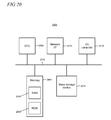
- FIG. 20 shows a block diagram of an illustrative computing platform that may be used in part to implement the present ergonomic PHIZ cursor mapping.
- FIG. 1 shows an illustrative computing environment 100 in which motions of a user 105 in a three dimensional (“3D”) physical space, representatively indicated by reference numeral 110 , are captured and mapped to a virtual space implemented using a user interface (“UI”) 115 shown on a 2D display 120 such as a television or monitor.
- UI user interface
- Such motion capture and mapping enables the user 105 to interact with various elements exposed by the UI 115 including control elements such as a cursor and buttons using body movements within the 3D physical space 110 .
- the cursor 125 is shaped like a hand.
- a given cursor may be allowed to traverse the entire screen area of the display, while in other scenarios an application executing in the environment 100 may only support cursor movement within a limited area of the UI 115 .
- the user 105 may interact with the UI 115 in a manner that extends beyond its visible borders.
- the UI 115 is described using a 2D coordinate system with x and y directions
- the 3D physical space 110 is described using a 3D coordinate system with x, y, and z directions. Motion of the user's hand in the x and y directions in the physical space 110 could thus be used to target a button 130 on the UI 115 , while motion in the z direction would enable the user 105 to press the button or perform other 3D interactions.
- User motion can be captured using a variety of techniques and equipment in which positioning of the user 105 and motion of various parts of the user's body within the physical space 110 may be determined.
- An optical sensor and computing platform as described in the text accompanying FIGS. 15-18 below may be utilized in some implementations. However, it is emphasized that optical sensors or camera systems are not the only types of equipment that may be used for motion capture.
- FIGS. 2-4 show a pictorial representation of an illustrative ergonomic PHIZ 205 . It is noted that the pictorial representations of the ergonomic PHIZ 205 are simplified for sake of clarity in exposition and that the actual size, shape, or location of the ergonomic PHIZ relative to the user 105 can be expected to vary from what is shown as needed to meet the needs of a particular implementation.
- the ergonomic PHIZ 205 is a 3D volume in the physical space in which the user 105 moves his hands. Hand motion within the ergonomic PHIZ results in cursor motion and interaction such as presses within a supported area on the UI.
- the PHIZ 205 is shaped, sized, and positioned relative to the user 105 to ergonomically match the user's natural range of motions so that the user can comfortably reach everything on the UI to advantageously enable interaction that is consistent and intuitive.
- a separate PHIZ can be provided for each of the user's hands in some implementations.
- the frontal area of the ergonomic PHIZ 205 spans approximately from the user's head to the mid portion of the torso.
- the area of the ergonomic PHIZ 205 will be sized relative to the user's size and location within the physical space.
- the ergonomic PHIZ 205 uses curved forward and back planes, as respectively indicated by reference numerals 310 and 315 .
- the curvature of the forward and back planes of the ergonomic PHIZ 205 takes the natural range of movement and extension of the user's arm into account. Such motion may be described, for example, in terms of rotation about the user's arm joints. These joints include the shoulder, elbow, and wrist, two of which (the shoulder and wrist) provide multiple degrees-of-freedom of motion. The position of the user's hand relative to the shoulder may be described using a spherical coordinate system in which the shoulder joint functions as the origin.
- the forward plane 310 of the ergonomic PHIZ will typically take a partially ellipsoidal shape with the long axis of the ellipsoid being along the y direction. This shape is due to the ergonomic motion of the user's arm in the physical space where moving in the y-z planet ends to involve rotation about both the shoulder and elbow joints, while moving in the x-y plane tends to involve rotation about only the shoulder joint.
- FIG. 5 shows an illustrative example of mapping between various points on the forward plane 310 of the ergonomic PHIZ (the perimeter of which is shown as a dashed line) and the UI 115 to implement cursor movement. It will be appreciated that the mapping for other points within the ergonomic PHIZ 205 to the UI 115 will be similar to what is shown in FIG. 5 .
- the arrows indicate that point 505 P in the PHIZ is mapped to point 505 UI in the UI, point 510 P is mapped to point 510 UI , point 515 p is mapped to point 515 UI , and point 520 P is mapped to point 520 UI .
- motion of the user's hand along line 525 P in the ergonomic PHIZ would correspond to cursor motion along line 525 UI in the UI.
- the mapping enables cursor motion in the x and y directions on the flat UI even though the forward plane of the PHIZ is curved to accommodate ergonomic motion.
- Motion of the user's hand in the z direction in the physical space may be measured, for example, by measuring the extension of the hand relative to the user's shoulder, in order to perform button presses or other actions on the UI.
- the mapping between the ergonomic PHIZ 205 and UI 115 can typically enable points at the extreme perimeter of the UI (indicated by the heavy line in FIG. 5 ) to be accessed by the user. However, the mapping may also be implemented in some cases so that positions within the ergonomic PHIZ 205 are mapped to points beyond the UI's visible boundaries. For example, point 530 P could map to point 530 UI that extends beyond the perimeter of the UI, as shown. Such mapping may enable a variety of UI interactions such as cursor-based manipulation of objects or content (e.g., a list, grid, etc.) that are larger than the display. In an illustrative example, the user can pan the objects/content with different velocities based on the cursor's distance from the UI edge and/or the user's direction of motion.
- the basic partially ellipsoidal shape of the ergonomic PHIZ may be tuned using a variety of parameters. Such tuning enables further refinement of the size, shape, or location of the PHIZ to provide ergonomic optimization across a population of users.
- An illustrative taxonomy of tuning parameters 600 is shown in FIG. 6 .
- the tuning parameters shown in FIG. 6 and described below are intended to be illustrative and the particular parameters utilized in a specific implementation can vary. It will be appreciated that tuning parameters other than those shown in FIG. 6 may also be utilized in some cases.
- the basic shape of the ergonomic PHIZ takes into account the rotation of the user's hand relative to the shoulder joint in the forward and up directions (tuning parameters 605 and 610 , respectively).
- Angular offsets can be added to center the ergonomic PHIZ in each of the horizontal and vertical directions with respect to the user ( 615 , 620 ).
- Angular horizontal and vertical ranges may also be applied to limit the amount of movement needed in the physical space to reach the extents of the UI ( 625 , 630 ).
- additional horizontal and vertical ranges are applied to accommodate the user's reach when closer than the furthest reach point ( 635 , 640 ).
- the linear distance from the user's shoulder to the hand is the current reach of the user.
- the length of the user's arm can be observed to use as a basis of the range of the user's reach.
- the ArmRatioToZeroTouch tuning parameter ( 645 ) is utilized to represent this portion of the user's arm length.
- the tuning parameter ShoulderToHandScaleVerticalMiddle ( 650 ) is a multiplier used to shorten the reach when at the middle of the vertical portion of the ergonomic PHIZ. As the user moves further up in the ergonomic PHIZ, the value of this parameter can linearly increase to return the user's reach to its full value.
- the forward plane is likewise tunable. For example, if the user's arm is capable of swinging a certain angular range, at full extension such maximum swing might prove to be uncomfortable for the user. By tuning the forward plane to reduce the angular range by some amount, the user's comfort at full arm extension can be increased while still being able to reach all of the desired area on the UI.
- the tuning parameters 600 may be statically utilized in some implementations where the parameters are selected a priori and applied to the ergonomic PHIZ in a manner that provides for comfortable and intuitive cursor control across a population of users.
- one or more tuning parameters may be dynamically applied and/or adjusted to meet the needs of an individual usage scenario. For example as shown in FIG. 7 , in scenarios where the user 105 is seated, the ergonomic PHIZ 705 may be reduced in size and positioned above the armrests 710 of the chair which tend to constrain the full motion of the user's arm. In such a case, the centering and range parameters may be dynamically adjusted so that the user 105 can comfortably reach and interact with all the control elements on the UI while seated.
- the tuning parameters can be dynamically adjusted again so that the ergonomic PHIZ is matched to the user's full and unconstrained arm motion. It may be desirable in some implementations where the tuning parameters are dynamically applied and/or adjusted to use motion data from more than one ergonomic PHIZ at a time in order to determine a final cursor position on the UI. For example, as shown in the flowchart 800 in FIG. 8 when the user is seated, the data from the smaller PHIZ noted above (termed the “seated ergonomic PHIZ”) is utilized for cursor mapping at step 805 .
- the final cursor position may be mapped using data from both the seated ergonomic PHIZ as well as the PHIZ shown in FIGS. 2-4 and described in the accompanying text (termed the “standing ergonomic PHIZ” for the purposes of this particular example).
- the data can be weighted or otherwise combined on a continuous basis, rather than selecting one discrete PHIZ or the other, to avoid sudden transitions and/or jumps in cursor movement that the user may not expect.
- the velocities of each of the PHIZs can be compared.
- the PHIZ that is consistently getting the greatest amount of velocity may be considered the one with which the user has the greatest desire to control the cursor.
- Some averaging and jerk filtering could also be used to prevent a sporadic movement in the non-active PHIZ from stealing priority from the active PHIZ. Increased priority or bias may also be given to the larger standing ergonomic PHIZ as well in some implementations.
- the cursor position on the UI is mapped using data solely from the standing ergonomic PHIZ.
- the determination of the user's orientation within the physical space may be determined by the motion capture system and/or related systems.
- skeleton tracking may be implemented in some systems in order to process gestures (i.e., any form of user movement that may be used as an input to a UI or interpreted as interaction with an application executing in the computing environment).
- FIGS. 9 and 10 respectively show a full skeleton model 905 and a seated skeleton model 1005 . As shown, the full skeleton model 905 includes 20 joints while the seated skeleton model 1005 includes only the upper 10 joints.
- FIGS. 11-13 respectively show the joint models used to implement a whole arm ergonomic PHIZ 205 , a forearm ergonomic PHIZ 1200 , and a hand ergonomic PHIZ 1300 .
- the whole arm ergonomic PHIZ may be utilized, for example, when the user's arm has a full range of motion without constraint.
- the whole arm ergonomic PHIZ 205 shown in FIG. 11 is the same PHIZ referred to in the text accompanying FIGS. 2-4 and 8 .
- the dashed lines in FIGS. 11-13 are simplified pictorial representations of the respective ergonomic PHIZs and the shapes of the actual PHIZs can vary from what are shown.
- the joint model 1105 underlying the whole arm ergonomic PHIZ 205 includes the shoulder, elbow, and wrist joints. As described above, the motion of the user's hand relative to the shoulder is used to map motion of the user's hand from the PHIZ to the UI.
- the forearm ergonomic PHIZ 1200 may be used, for example, when the full motion of the user's arm is constrained such as when the user's elbow is resting on an arm of a chair, as illustratively shown in FIG. 7 .
- the joint model 1205 underlying the forearm ergonomic PHIZ 1200 includes the elbow and wrist joints. The motion of the user's hand relative to the elbow is used to map motion of the user's hand from the PHIZ to the UI. Accordingly, the origin of the spherical coordinate system would be located at the elbow joint for the forearm ergonomic PHIZ 1200 .
- tuning parameters may be applied to the forearm ergonomic PHIZ 1200 , for example, to adjust for horizontal and vertical centering as well as horizontal and vertical range.
- the hand ergonomic PHIZ 1300 may be used, for example, when the user's forearm is constrained.
- the user could be lying on the floor, a bed, or a couch in a way that constrains full motion of the forearm.
- the user could be standing but with a hand bag or coat hanging on his/her arm which constrains motion.
- the view of the user could be partially obscured.
- the user could be sitting on a couch with a laptop or dinner tray on his lap which blocks the sensor view at the mid-body and an end of the couch blocks arm movement at the side of the user's body.
- the cursor mapping may be performed using the motion of the user's hands or fingertips relative to some other origin point or identifiable feature such as a vector projecting forward from the user's body.
- the use of fingertips to map cursor motion may also enable scenarios in which the location of the hand is used to perform coarse cursor movement while the fingertip position provides fine grain control.
- FIG. 14 is a flowchart for an illustrative method 1400 for calibrating a physical space, dynamically changing cursor mapping, and dynamically selecting among the multiple PHIZs of different sizes and shapes.
- the method starts at step 1405 where the physical space 110 ( FIG. 1 ) is calibrated. This step may be optionally performed, since having a user perform explicit calibration tasks may not be appropriate in all usage scenarios.
- the physical space calibration may include measuring the user's preferred position by offering a single button on the UI, for example located on the top left corner, to be pressed. When the user presses that button, the position of the press is taken and used to compute adjusted horizontal and vertical centering parameters. This technique may also be extended to achieve calibration for ranges and reach to press distances.
- the tuning parameters may be further adjusted based on a number of calibration inputs that have varying degrees of confidence.
- Data from the single button press calibration may be aggregated over a population of users. By having users perform proscribed presses they nominally define a line in three spaces. By taking all defined lines for all users in the population, an ideal PHIZ shape can be created that minimizes x and y drift for the users.
- An initial ergonomic PHIZ is selected at step 1410 .
- the position of the user within the physical space and any constraints on user motion can be factors in making the selection. For example, if the user is seated, then the forearm ergonomic PHIZ can be initially selected. If the user is standing and has unconstrained arm motion, then the whole arm PHIZ can be initially selected.
- one or more of the tuning parameters 600 can be dynamically adjusted to tailor the ergonomic PHIZ to the particular context in which it is being used. Any of a number of contextual factors may be considered for such dynamic adjustment which can alter the size, shape, and/or location of the ergonomic PHIZ. These include, for example, the set-up of the particular motion capture system that is being utilized, the user's position within the physical space (e.g., how far away from the optical sensor in implementations where such device is being used), as well as the specific context provided by an application. In some implementations, the context may include past behaviors of the user which may be used to identify patterns that may be utilized to dynamically apply the tuning parameters 600 to the ergonomic PHIZ.
- the tuning parameters can adjust the size, shape, and location of the PHIZ in the physical space depending on what is being shown on the UI and how it is being shown. For example, if the application deals with the presentation of media content such as a movie or television show, the transport controls (e.g., stop/start/pause/fast forward/fast back/skip ahead/skip back, etc.) may be presented as a horizontal array of buttons on the bottom of the UI below the displayed content. In this case, the tuning parameters may be dynamically adjusted to shape the ergonomic PHIZ in a way that makes the buttons large and easy to target and press within the physical space while still appearing normal and small on the UI.
- the transport controls e.g., stop/start/pause/fast forward/fast back/skip ahead/skip back, etc.
- the tuning parameters may be dynamically adjusted to shape the ergonomic PHIZ in a way that makes the buttons large and easy to target and press within the physical space while still appearing normal and small on the UI.
- another ergonomic PHIZ can be selected as the context changes. For example, if the user sits down and his arm becomes constrained, the whole arm ergonomic PHIZ can be swapped out for the forearm PHIZ. The lower half of the user may become occluded from view of an optical sensor (for example if the user moves within the physical space behind a chair or other piece of furniture), in which case it may also be advantageous to switch to the forearm ergonomic PHIZ. As with the illustrative example shown in FIG. 8 and described in the accompanying text, the selection between ergonomic PHIZs may be performed continuously, rather than discretely, to avoid any jarring or sudden transitions that the user does not expect. However, discrete ergonomic PHIZ selection might be desirable in some applications.
- Control returns to step 1415 where tuning parameters for the newly selected ergonomic PHIZ may be dynamically adjusted based on context.
- FIG. 15 shows a particular illustrative computing environment 1500 in which the present ergonomic PHIZ cursor mapping may be implemented.
- the environment 1500 includes a computing platform such as multimedia console 1503 that is typically configured for running gaming and non-gaming applications using local and/or networked programming and content, playing pre-recorded multimedia such as optical discs including DVDs (Digital Versatile Discs) and CDs (Compact Discs), streaming multimedia from a network, participating in social media, browsing the Internet and other networked media and content, or the like, using a coupled audio/visual display 1508 , such as a television to display the UI.
- the multimedia console can be replaced by a suitably adapted personal computer (“PC”) such as a desktop, laptop, or notebook PC, tablet, or similar computing platform.
- PC personal computer
- the multimedia console 1503 in this example is operatively coupled to an optical sensor 1513 which may be implemented using one or more video cameras that are configured to visually monitor the physical space 110 (indicated generally by the dashed line in FIG. 15 ) that is occupied by the user 105 .
- the optical sensor 1513 is configured to capture, track, and analyze the movements and/or gestures of the user 105 so that they can be used as controls that may be employed to affect, for example, an application or an operating system running on the multimedia console 1503 .
- Various motions of the hands 1521 or other body parts of the user 105 may correspond to common system-wide tasks such as selecting a game or other application from a main user interface.
- the user 105 can navigate among selectable objects 1522 that include various icons 1525 1-N that are shown on the coupled display 1508 , browse through items in a hierarchical menu, open a file, close a file, save a file, or the like.
- the user 105 may use movements and/or gestures to end, pause, or save a game, select a level, view high scores, communicate with a friend, etc.
- Virtually any controllable aspect of an operating system and/or application may be controlled by movements of the user 105 .
- a cursor or similar device will be displayed on the UI to aid the user in interacting with the console and applications that execute on it.
- a full range of motion of the user 105 may be available, used, and analyzed in any suitable manner to interact with an application or operating system that executes in the environment 1500 .
- the optical sensor 1513 can also be utilized to capture, track, and analyze movements by the user 105 to control gameplay as a gaming application executes on the multimedia console 1503 .
- a gaming application such as a boxing game uses the display 1508 to provide a visual representation of a boxing opponent to the user 105 as well as a visual representation of a player avatar that the user 105 may control with his or her movements.
- the user 105 may make movements (e.g., throwing a punch) in the physical space 110 to cause the player avatar to make a corresponding movement in the game space. Movements of the user 105 may be recognized and analyzed in the physical space 110 such that corresponding movements for game control of the player avatar in the game space are performed.
- the optical sensor 1513 may be configured to capture video with depth information including a depth image that may include depth values via any suitable technique including, for example, time-of-flight, structured light, stereo image, or the like.
- the optical sensor 1513 may organize the calculated depth information into “z layers,” or layers that may be perpendicular to a z axis extending from the depth camera along its line of sight.
- the optical sensor 1513 includes an image capture component 1703 .
- the image capture component 1703 may be configured to operate as a depth camera that may capture a depth image of a scene.
- the depth image may include a 2D pixel area of the captured scene where each pixel in the 2D pixel area may represent a depth value such as a distance in, for example, centimeters, millimeters, or the like of an object in the captured scene from the camera.
- the image capture component 1703 includes an IR light component 1706 , an IR camera 1711 , and a visible light RGB camera 1714 that are configured in an array.
- the IR light component 1706 of the optical sensor 1513 may emit an infrared light onto the capture area and may then detect the backscattered light from the surface of one or more targets and objects in the capture area using, for example, the IR camera 1711 and/or the RGB camera 1714 .
- pulsed infrared light may be used such that the time between an outgoing light pulse and a corresponding incoming light pulse may be measured and used to determine a physical distance from the optical sensor 1513 to a particular location on the targets or objects in the capture area.
- the phase of the outgoing light wave may be compared to the phase of the incoming light wave to determine a phase shift.
- the phase shift may then be used to determine a physical distance from the optical sensor to a particular location on the targets or objects.
- Time-of-flight analysis may be used to indirectly determine a physical distance from the optical sensor 1513 to a particular location on the targets or objects by analyzing the intensity of the reflected beam of light over time via various techniques including, for example, shuttered light pulse imaging.
- the optical sensor 1513 may use structured light to capture depth information.
- patterned light i.e., light displayed as a known pattern such as a grid pattern or a stripe pattern
- the pattern may become deformed in response.
- Such a deformation of the pattern may be captured by, for example, the IR camera 1711 and/or the RGB camera 1714 and may then be analyzed to determine a physical distance from the optical sensor to a particular location on the targets or objects.
- the optical sensor 1513 may utilize two or more physically separated cameras that may view a capture area from different angles, to obtain visual stereo data that may be resolved to generate depth information. Other types of depth image arrangements using single or multiple cameras can also be used to create a depth image.
- the optical sensor 1513 may further include a microphone 1718 .
- the microphone 1718 may include a transducer or sensor that may receive and convert sound into an electrical signal.
- the microphone 1718 may be used to reduce feedback between the optical sensor 1513 and the multimedia console 1503 in the target recognition, analysis, and tracking system 1700 . Additionally, the microphone 1718 may be used to receive audio signals that may also be provided by the user 105 to control applications such as game applications, non-game applications, or the like that may be executed by the multimedia console 1503 .
- the optical sensor 1513 may further include a processor 1725 that may be in operative communication with the image capture component 1703 over a bus 1728 .
- the processor 1725 may include a standardized processor, a specialized processor, a microprocessor, or the like that may execute instructions that may include instructions for storing profiles, receiving the depth image, determining whether a suitable target may be included in the depth image, converting the suitable target into a skeletal representation or model of the target, or any other suitable instruction.
- the optical sensor 1513 may further include a memory component 1732 that may store the instructions that may be executed by the processor 1725 , images or frames of images captured by the cameras, user profiles or any other suitable information, images, or the like.
- the memory component 1732 may include random access memory (RAM), read only memory (ROM), cache, Flash memory, a hard disk, or any other suitable storage component. As shown in FIG. 17 , the memory component 1732 may be a separate component in communication with the image capture component 1703 and the processor 1725 . Alternatively, the memory component 1732 may be integrated into the processor 1725 and/or the image capture component 1703 . In one embodiment, some or all of the components 1703 , 1706 , 1711 , 1714 , 1718 , 1725 , 1728 , and 1732 of the optical sensor 1513 are located in a single housing.
- the optical sensor 1513 operatively communicates with the multimedia console 1503 over a communication link 1735 .
- the communication link 1735 may be a wired connection including, for example, a USB (Universal Serial Bus) connection, a Firewire connection, an Ethernet cable connection, or the like and/or a wireless connection such as a wireless IEEE 802.11 connection.
- the multimedia console 1503 can provide a clock to the optical sensor 1513 that may be used to determine when to capture, for example, a scene via the communication link 1735 .
- the optical sensor 1513 may provide the depth information and images captured by, for example, the IR camera 1711 and/or the RGB camera 1714 , including a skeletal model and/or facial tracking model that may be generated by the optical sensor 1513 , to the multimedia console 1503 via the communication link 1735 .
- the multimedia console 1503 may then use the skeletal and/or facial tracking models, depth information, and captured images to, for example, create a virtual screen, adapt the user interface, and control an application.
- a motion tracking engine 1741 uses the skeletal and/or facial tracking models and the depth information to provide a control output to one more applications (representatively indicated by an application 1745 in FIG. 17 ) running on the multimedia console 1503 to which the optical sensor 1513 is coupled.
- the information may also be used by a gesture recognition engine 1751 , depth image processing engine 1754 , and/or operating system 1759 .
- the depth image processing engine 1754 uses the depth images to track motion of objects, such as the user and other objects.
- the depth image processing engine 1754 will typically report to operating system 1759 an identification of each object detected and the location of the object for each frame.
- the operating system 1759 can use that information to update the position or movement of an avatar, for example, or other images shown on the display 1508 , or to perform an action on the user interface.
- the gesture recognition engine 1751 may utilize a gestures library (not shown) that can include a collection of gesture filters, each comprising information concerning a gesture that may be performed, for example, by a skeletal model (as the user moves).
- the gesture recognition engine 1751 may compare the frames captured by the optical sensor 1513 in the form of the skeletal model and movements associated with it to the gesture filters in the gesture library to identify when a user (as represented by the skeletal model) has performed one or more gestures. Those gestures may be associated with various controls of an application.
- the multimedia console 1503 may employ the gestures library to interpret movements of the skeletal model and to control an operating system or an application running on the multimedia console based on the movements.
- various aspects of the functionalities provided by the applications 1745 , motion tracking engine 1741 , gesture recognition engine 1751 , depth image processing engine 1754 , and/or operating system 1759 may be directly implemented on the optical sensor 1513 itself.
- FIG. 18 is an illustrative functional block diagram of the multimedia console 1503 shown in FIGS. 15-17 .
- the multimedia console 1503 has a central processing unit (CPU) 1801 having a level 1 cache 1802 , a level 2 cache 1804 , and a Flash ROM (Read Only Memory) 1806 .
- the level 1 cache 1802 and the level 2 cache 1804 temporarily store data and hence reduce the number of memory access cycles, thereby improving processing speed and throughput.
- the CPU 1801 may be configured with more than one core, and thus, additional level 1 and level 2 caches 1802 and 1804 .
- the Flash ROM 1806 may store executable code that is loaded during an initial phase of a boot process when the multimedia console 1503 is powered ON.
- a graphics processing unit (GPU) 1808 and a video encoder/video codec (coder/decoder) 1814 form a video processing pipeline for high speed and high resolution graphics processing. Data is carried from the GPU 1808 to the video encoder/video codec 1814 via a bus. The video processing pipeline outputs data to an A/V (audio/video) port 1840 for transmission to a television or other display.
- a memory controller 1810 is connected to the GPU 1808 to facilitate processor access to various types of memory 1812 , such as, but not limited to, a RAM.
- the multimedia console 1503 includes an I/O controller 1820 , a system management controller 1822 , an audio processing unit 1823 , a network interface controller 1824 , a first USB host controller 1826 , a second USB controller 1828 , and a front panel I/O subassembly 1830 that are preferably implemented on a module 1818 .
- the USB controllers 1826 and 1828 serve as hosts for peripheral controllers 1842 ( 1 )- 1842 ( 2 ), a wireless adapter 1848 , and an external memory device 1846 (e.g., Flash memory, external CD/DVD ROM drive, removable media, etc.).
- the network interface controller 1824 and/or wireless adapter 1848 provide access to a network (e.g., the Internet, home network, etc.) and may be any of a wide variety of various wired or wireless adapter components including an Ethernet card, a modem, a Bluetooth module, a cable modem, and the like.
- a network e.g., the Internet, home network, etc.
- wired or wireless adapter components including an Ethernet card, a modem, a Bluetooth module, a cable modem, and the like.
- System memory 1843 is provided to store application data that is loaded during the boot process.
- a media drive 1844 is provided and may comprise a DVD/CD drive, hard drive, or other removable media drive, etc.
- the media drive 1844 may be internal or external to the multimedia console 1503 .
- Application data may be accessed via the media drive 1844 for execution, playback, etc. by the multimedia console 1503 .
- the media drive 1844 is connected to the I/O controller 1820 via a bus, such as a Serial ATA bus or other high speed connection (e.g., IEEE 1394).
- the system management controller 1822 provides a variety of service functions related to assuring availability of the multimedia console 1503 .
- the audio processing unit 1823 and an audio codec 1832 form a corresponding audio processing pipeline with high fidelity and stereo processing. Audio data is carried between the audio processing unit 1823 and the audio codec 1832 via a communication link.
- the audio processing pipeline outputs data to the A/V port 1840 for reproduction by an external audio player or device having audio capabilities.
- the front panel I/O subassembly 1830 supports the functionality of the power button 1850 and the eject button 1852 , as well as any LEDs (light emitting diodes) or other indicators exposed on the outer surface of the multimedia console 1503 .
- a system power supply module 1836 provides power to the components of the multimedia console 1503 .
- a fan 1838 cools the circuitry within the multimedia console 1503 .
- the CPU 1801 , GPU 1808 , memory controller 1810 , and various other components within the multimedia console 1503 are interconnected via one or more buses, including serial and parallel buses, a memory bus, a peripheral bus, and a processor or local bus using any of a variety of bus architectures.
- bus architectures can include a Peripheral Component Interconnects (“PCI”) bus, PCI-Express bus, etc.
- application data may be loaded from the system memory 1843 into memory 1812 and/or caches 1802 and 1804 and executed on the CPU 1801 .
- the application may present a graphical user interface that provides a consistent user experience when navigating to different media types available on the multimedia console 1503 .
- applications and/or other media contained within the media drive 1844 may be launched or played from the media drive 1844 to provide additional functionalities to the multimedia console 1503 .
- the multimedia console 1503 may be operated as a standalone system by simply connecting the system to a television or other display. In this standalone mode, the multimedia console 1503 allows one or more users to interact with the system, watch movies, or listen to music. However, with the integration of broadband connectivity made available through the network interface controller 1824 or the wireless adapter 1848 , the multimedia console 1503 may further be operated as a participant in a larger network community.
- a set amount of hardware resources are reserved for system use by the multimedia console operating system. These resources may include a reservation of memory (e.g., 16 MB), CPU and GPU cycles (e.g., 5%), networking bandwidth (e.g., 8 kbs), etc. Because these resources are reserved at system boot time, the reserved resources do not exist from the application's point of view.
- the memory reservation is preferably large enough to contain the launch kernel, concurrent system applications, and drivers.
- the CPU reservation is preferably constant such that if the reserved CPU usage is not used by the system applications, an idle thread will consume any unused cycles.
- lightweight messages generated by the system applications are displayed by using a GPU interrupt to schedule code to render pop-ups into an overlay.
- the amount of memory needed for an overlay depends on the overlay area size, and the overlay preferably scales with screen resolution. Where a full user interface is used by the concurrent system application, it is preferable to use a resolution independent of application resolution. A scaler may be used to set this resolution such that the need to change frequency and cause a TV re-sync is eliminated.
- the multimedia console 1503 boots and system resources are reserved, concurrent system applications execute to provide system functionalities.
- the system functionalities are encapsulated in a set of system applications that execute within the reserved system resources described above.
- the operating system kernel identifies threads that are system application threads versus gaming application threads.
- the system applications are preferably scheduled to run on the CPU 1801 at predetermined times and intervals in order to provide a consistent system resource view to the application. The scheduling is to minimize cache disruption for the gaming application running on the console.
- a multimedia console application manager controls the gaming application audio level (e.g., mute, attenuate) when system applications are active.
- Input devices are shared by gaming applications and system applications.
- the input devices are not reserved resources, but are to be switched between system applications and the gaming application such that each will have a focus of the device.
- the application manager preferably controls the switching of input stream, without knowledge of the gaming application's knowledge and a driver maintains state information regarding focus switches.
- the optical sensor 1513 may define additional input devices for the console 1503 .
- FIG. 19 is a simplified block diagram of an illustrative computer system 1900 such as a PC, client machine, or server with which the present ergonomic PHIZ cursor mapping may be implemented.
- Computer system 1900 includes a processing unit 1905 , a system memory 1911 , and a system bus 1914 that couples various system components including the system memory 1911 to the processing unit 1905 .
- the system bus 1914 may be any of several types of bus structures including a memory bus or memory controller, a peripheral bus, and a local bus using any of a variety of bus architectures.
- the system memory 1911 includes read only memory (“ROM”) 1917 and random access memory (“RAM”) 1921 .
- ROM read only memory
- RAM random access memory
- a basic input/output system (“BIOS”) 1925 containing the basic routines that help to transfer information between elements within the computer system 1900 , such as during startup, is stored in ROM 1917 .
- the computer system 1900 may further include a hard disk drive 1928 for reading from and writing to an internally disposed hard disk (not shown), a magnetic disk drive 1930 for reading from or writing to a removable magnetic disk 1933 (e.g., a floppy disk), and an optical disk drive 1938 for reading from or writing to a removable optical disk 1943 such as a CD (compact disc), DVD (digital versatile disc), or other optical media.
- the hard disk drive 1928 , magnetic disk drive 1930 , and optical disk drive 1938 are connected to the system bus 1914 by a hard disk drive interface 1946 , a magnetic disk drive interface 1949 , and an optical drive interface 1952 , respectively.
- the drives and their associated computer readable storage media provide non-volatile storage of computer readable instructions, data structures, program modules, and other data for the computer system 1900 .
- this illustrative example shows a hard disk, a removable magnetic disk 1933 , and a removable optical disk 1943
- other types of computer readable storage media which can store data that is accessible by a computer such as magnetic cassettes, flash memory cards, digital video disks, data cartridges, random access memories (“RAMs”), read only memories (“ROMs”), and the like may also be used in some applications of the present ergonomic PHIZ cursor mapping.
- the term computer readable storage medium includes one or more instances of a media type (e.g., one or more magnetic disks, one or more CDs, etc.).
- the phrase “computer-readable storage media” and variations thereof does not include waves, signals, and/or other transitory and/or intangible communication media.
- a number of program modules may be stored on the hard disk, magnetic disk 1933 , optical disk 1943 , ROM 1917 , or RAM 1921 , including an operating system 1955 , one or more application programs 1957 , other program modules 1960 , and program data 1963 .
- a user may enter commands and information into the computer system 1900 through input devices such as a keyboard 1966 and pointing device 1968 such as a mouse.
- Other input devices may include a microphone, joystick, game pad, satellite dish, scanner, trackball, touchpad, touch screen, touch-sensitive device, voice recognition module or device, voice command module or device, or the like.
- serial port interface 1971 that is coupled to the system bus 1914 , but may be connected by other interfaces, such as a parallel port, game port, or universal serial bus (“USB”).
- a monitor 1973 or other type of display device is also connected to the system bus 1914 via an interface, such as a video adapter 1975 .
- personal computers typically include other peripheral output devices (not shown), such as speakers and printers.
- the illustrative example shown in FIG. 19 also includes a host adapter 1978 , a Small Computer System Interface (“SCSI”) bus 1983 , and an external storage device 1976 connected to the SCSI bus 1983 .
- SCSI Small Computer System Interface
- the computer system 1900 is operable in a networked environment using logical connections to one or more remote computers, such as a remote computer 1988 .
- the remote computer 1988 may be selected as another personal computer, a server, a router, a network PC, a peer device, or other common network node, and typically includes many or all of the elements described above relative to the computer system 1900 , although only a single representative remote memory/storage device 1990 is shown in FIG. 19 .
- the logical connections depicted in FIG. 19 include a local area network (“LAN”) 1993 and a wide area network (“WAN”) 1995 .
- LAN local area network
- WAN wide area network
- Such networking environments are often deployed, for example, in offices, enterprise-wide computer networks, intranets, and the Internet.
- the computer system 1900 When used in a LAN networking environment, the computer system 1900 is connected to the local area network 1993 through a network interface or adapter 1996 .
- the computer system 1900 When used in a WAN networking environment, the computer system 1900 typically includes a broadband modem 1998 , network gateway, or other means for establishing communications over the wide area network 1995 , such as the Internet.
- the broadband modem 1998 which may be internal or external, is connected to the system bus 1914 via a serial port interface 1971 .
- program modules related to the computer system 1900 may be stored in the remote memory storage device 1990 . It is noted that the network connections shown in FIG. 19 are illustrative and other means of establishing a communications link between the computers may be used depending on the specific requirements of an application of ergonomic PHIZ cursor mapping.
- FIG. 20 shows an illustrative architecture 2000 for a computing platform or device capable of executing the various components described herein for providing ergonomic PHIZ cursor mapping.
- the architecture 2000 illustrated in FIG. 20 shows an architecture that may be adapted for a server computer, mobile phone, a PDA (personal digital assistant), a smartphone, a desktop computer, a netbook computer, a tablet computer, GPS (Global Positioning System) device, gaming console, and/or a laptop computer.
- the architecture 2000 may be utilized to execute any aspect of the components presented herein.
- the architecture 2000 illustrated in FIG. 20 includes a CPU 2002 , a system memory 2004 , including a RAM 2006 and a ROM 2008 , and a system bus 2010 that couples the memory 2004 to the CPU 2002 .
- the architecture 2000 further includes a mass storage device 2012 for storing software code or other computer-executed code that is utilized to implement applications, the file system, and the operating system.
- the mass storage device 2012 is connected to the CPU 2002 through a mass storage controller (not shown) connected to the bus 2010 .
- the mass storage device 2012 and its associated computer-readable storage media provide non-volatile storage for the architecture 2000 .
- computer-readable storage media can be any available computer storage media that can be accessed by the architecture 2000 .
- computer-readable storage media can be any available storage media that can be accessed by the architecture 2000 .
- computer-readable storage media may include volatile and non-volatile, removable and non-removable media implemented in any method or technology for storage of information such as computer-readable instructions, data structures, program modules or other data.
- computer-readable media includes, but is not limited to, RAM, ROM, EPROM (erasable programmable read only memory), EEPROM (electrically erasable programmable read only memory), Flash memory or other solid state memory technology, CD-ROM, DVDs, HD-DVD (High Definition DVD), BLU-RAY, or other optical storage, magnetic cassettes, magnetic tape, magnetic disk storage or other magnetic storage devices, or any other medium which can be used to store the desired information and which can be accessed by the architecture 2000 .
- the architecture 2000 may operate in a networked environment using logical connections to remote computers through a network.
- the architecture 2000 may connect to the network through a network interface unit 2016 connected to the bus 2010 .
- the network interface unit 2016 also may be utilized to connect to other types of networks and remote computer systems.
- the architecture 2000 also may include an input/output controller 2018 for receiving and processing input from a number of other devices, including a keyboard, mouse, or electronic stylus (not shown in FIG. 20 ).
- the input/output controller 2018 may provide output to a display screen, a printer, or other type of output device (also not shown in FIG. 20 ).
- the software components described herein may, when loaded into the CPU 2002 and executed, transform the CPU 2002 and the overall architecture 2000 from a general-purpose computing system into a special-purpose computing system customized to facilitate the functionality presented herein.
- the CPU 2002 may be constructed from any number of transistors or other discrete circuit elements, which may individually or collectively assume any number of states. More specifically, the CPU 2002 may operate as a finite-state machine, in response to executable instructions contained within the software modules disclosed herein. These computer-executable instructions may transform the CPU 2002 by specifying how the CPU 2002 transitions between states, thereby transforming the transistors or other discrete hardware elements constituting the CPU 2002 .
- Encoding the software modules presented herein also may transform the physical structure of the computer-readable storage media presented herein.
- the specific transformation of physical structure may depend on various factors, in different implementations of this description. Examples of such factors may include, but are not limited to, the technology used to implement the computer-readable storage media, whether the computer-readable storage media is characterized as primary or secondary storage, and the like.
- the computer-readable storage media is implemented as semiconductor-based memory
- the software disclosed herein may be encoded on the computer-readable storage media by transforming the physical state of the semiconductor memory.
- the software may transform the state of transistors, capacitors, or other discrete circuit elements constituting the semiconductor memory.
- the software also may transform the physical state of such components in order to store data thereupon.
- the computer-readable storage media disclosed herein may be implemented using magnetic or optical technology.
- the software presented herein may transform the physical state of magnetic or optical media, when the software is encoded therein. These transformations may include altering the magnetic characteristics of particular locations within given magnetic media. These transformations also may include altering the physical features or characteristics of particular locations within given optical media to change the optical characteristics of those locations. Other transformations of physical media are possible without departing from the scope and spirit of the present description, with the foregoing examples provided only to facilitate this discussion.
- the architecture 2000 may include other types of computing devices, including hand-held computers, embedded computer systems, smartphones, PDAs, and other types of computing devices known to those skilled in the art. It is also contemplated that the architecture 2000 may not include all of the components shown in FIG. 20 , may include other components that are not explicitly shown in FIG. 20 , or may utilize an architecture completely different from that shown in FIG. 20 .
Landscapes
- Engineering & Computer Science (AREA)
- Theoretical Computer Science (AREA)
- General Engineering & Computer Science (AREA)
- Human Computer Interaction (AREA)
- Physics & Mathematics (AREA)
- General Physics & Mathematics (AREA)
- Health & Medical Sciences (AREA)
- Computer Vision & Pattern Recognition (AREA)
- General Health & Medical Sciences (AREA)
- Psychiatry (AREA)
- Social Psychology (AREA)
- Multimedia (AREA)
- User Interface Of Digital Computer (AREA)
- Position Input By Displaying (AREA)
Priority Applications (6)
| Application Number | Priority Date | Filing Date | Title |
|---|---|---|---|
| US13/955,229 US9063578B2 (en) | 2013-07-31 | 2013-07-31 | Ergonomic physical interaction zone cursor mapping |
| CN201480043401.3A CN105723301B (zh) | 2013-07-31 | 2014-07-28 | 人体工程学计算机交互方法 |
| PCT/US2014/048340 WO2015017294A1 (en) | 2013-07-31 | 2014-07-28 | Ergonomic physical interaction zone cursor mapping |
| EP14750130.8A EP3028120A1 (en) | 2013-07-31 | 2014-07-28 | Ergonomic physical interaction zone cursor mapping |
| KR1020167005303A KR102296967B1 (ko) | 2013-07-31 | 2014-07-28 | 인체 공학적 물리적 상호작용 구역 커서 매핑 |
| US14/721,471 US9342160B2 (en) | 2013-07-31 | 2015-05-26 | Ergonomic physical interaction zone cursor mapping |
Applications Claiming Priority (1)
| Application Number | Priority Date | Filing Date | Title |
|---|---|---|---|
| US13/955,229 US9063578B2 (en) | 2013-07-31 | 2013-07-31 | Ergonomic physical interaction zone cursor mapping |
Related Child Applications (1)
| Application Number | Title | Priority Date | Filing Date |
|---|---|---|---|
| US14/721,471 Continuation US9342160B2 (en) | 2013-07-31 | 2015-05-26 | Ergonomic physical interaction zone cursor mapping |
Publications (2)
| Publication Number | Publication Date |
|---|---|
| US20150035750A1 US20150035750A1 (en) | 2015-02-05 |
| US9063578B2 true US9063578B2 (en) | 2015-06-23 |
Family
ID=51300904
Family Applications (2)
| Application Number | Title | Priority Date | Filing Date |
|---|---|---|---|
| US13/955,229 Active 2033-12-25 US9063578B2 (en) | 2013-07-31 | 2013-07-31 | Ergonomic physical interaction zone cursor mapping |
| US14/721,471 Active US9342160B2 (en) | 2013-07-31 | 2015-05-26 | Ergonomic physical interaction zone cursor mapping |
Family Applications After (1)
| Application Number | Title | Priority Date | Filing Date |
|---|---|---|---|
| US14/721,471 Active US9342160B2 (en) | 2013-07-31 | 2015-05-26 | Ergonomic physical interaction zone cursor mapping |
Country Status (5)
| Country | Link |
|---|---|
| US (2) | US9063578B2 (zh) |
| EP (1) | EP3028120A1 (zh) |
| KR (1) | KR102296967B1 (zh) |
| CN (1) | CN105723301B (zh) |
| WO (1) | WO2015017294A1 (zh) |
Cited By (3)
| Publication number | Priority date | Publication date | Assignee | Title |
|---|---|---|---|---|
| US20100269062A1 (en) * | 2009-04-15 | 2010-10-21 | International Business Machines, Corpoation | Presenting and zooming a set of objects within a window |
| US10452195B2 (en) | 2014-12-30 | 2019-10-22 | Samsung Electronics Co., Ltd. | Electronic system with gesture calibration mechanism and method of operation thereof |
| US11341674B2 (en) | 2020-06-17 | 2022-05-24 | Microsoft Technology Licensing, Llc | Determining an object's 3D orientation from a single camera's image |
Families Citing this family (29)
| Publication number | Priority date | Publication date | Assignee | Title |
|---|---|---|---|---|
| US9501152B2 (en) | 2013-01-15 | 2016-11-22 | Leap Motion, Inc. | Free-space user interface and control using virtual constructs |
| US11493998B2 (en) | 2012-01-17 | 2022-11-08 | Ultrahaptics IP Two Limited | Systems and methods for machine control |
| US9459697B2 (en) | 2013-01-15 | 2016-10-04 | Leap Motion, Inc. | Dynamic, free-space user interactions for machine control |
| USD748136S1 (en) * | 2013-02-23 | 2016-01-26 | Samsung Electronics Co., Ltd. | Display screen or portion thereof with icon |
| US9671868B2 (en) | 2013-06-11 | 2017-06-06 | Honeywell International Inc. | System and method for volumetric computing |
| US10281987B1 (en) | 2013-08-09 | 2019-05-07 | Leap Motion, Inc. | Systems and methods of free-space gestural interaction |
| KR102166330B1 (ko) * | 2013-08-23 | 2020-10-15 | 삼성메디슨 주식회사 | 의료 진단 장치의 사용자 인터페이스 제공 방법 및 장치 |
| KR101700817B1 (ko) * | 2014-01-10 | 2017-02-13 | 한국전자통신연구원 | 3차원 영상을 이용한 다수의 팔 및 손 검출 장치 및 그 방법 |
| US9785243B2 (en) * | 2014-01-30 | 2017-10-10 | Honeywell International Inc. | System and method for providing an ergonomic three-dimensional, gesture based, multimodal interface for use in flight deck applications |
| US9807340B2 (en) * | 2014-11-25 | 2017-10-31 | Electronics And Telecommunications Research Institute | Method and apparatus for providing eye-contact function to multiple points of attendance using stereo image in video conference system |
| US9740010B2 (en) * | 2014-11-28 | 2017-08-22 | Mahmoud A. ALHASHIM | Waterproof virtual reality goggle and sensor system |
| KR101659849B1 (ko) * | 2015-01-09 | 2016-09-29 | 한국과학기술원 | 아바타를 이용한 텔레프레즌스 제공 방법, 상기 방법을 수행하는 시스템 및 컴퓨터 판독 가능한 기록 매체 |
| US9811165B2 (en) * | 2015-03-11 | 2017-11-07 | Samsung Electronics Co., Ltd. | Electronic system with gesture processing mechanism and method of operation thereof |
| CN104866096B (zh) * | 2015-05-18 | 2018-01-05 | 中国科学院软件研究所 | 一种利用上臂伸展信息进行命令选择的方法 |
| CN107960124B (zh) * | 2016-05-16 | 2021-02-26 | 深圳维盛半导体科技有限公司 | 一种dpi自动调节的鼠标及方法 |
| US10037626B2 (en) | 2016-06-30 | 2018-07-31 | Microsoft Technology Licensing, Llc | Interaction with virtual objects based on determined restrictions |
| KR102239855B1 (ko) * | 2016-07-22 | 2021-04-13 | 구글 엘엘씨 | 가상 현실 사용자 인터페이스를 위한 사용자 모션 범위의 검출 |
| USD844664S1 (en) * | 2016-08-02 | 2019-04-02 | Smule, Inc. | Display screen or portion thereof with animated graphical user interface |
| USD815147S1 (en) * | 2016-08-12 | 2018-04-10 | Gemalto Sa | Display screen with graphical user interface |
| USD830412S1 (en) * | 2016-08-15 | 2018-10-09 | Gemalto Sa | Display screen with graphical user interface |
| CN106250711B (zh) * | 2016-08-18 | 2019-12-06 | 青岛海信医疗设备股份有限公司 | 一种用于医疗显示的光标移动方法、装置和医疗设备 |
| CN107145220A (zh) * | 2017-03-24 | 2017-09-08 | 深圳奥比中光科技有限公司 | 人机交互自适应调整方法及系统 |
| DE102017216000A1 (de) * | 2017-09-11 | 2019-03-14 | Conti Temic Microelectronic Gmbh | Gestensteuerung zur Kommunikation mit einem autonomen Fahrzeug auf Basis einer einfachen 2D Kamera |
| USD870152S1 (en) | 2018-01-04 | 2019-12-17 | Samsung Electronics Co., Ltd. | Display screen or portion thereof with transitional graphical user interface |
| US11113887B2 (en) * | 2018-01-08 | 2021-09-07 | Verizon Patent And Licensing Inc | Generating three-dimensional content from two-dimensional images |
| USD900872S1 (en) * | 2018-08-31 | 2020-11-03 | General Electric Company | Display screen or portion thereof with icon |
| US20200296462A1 (en) | 2019-03-11 | 2020-09-17 | Wci One, Llc | Media content presentation |
| CN110908504B (zh) * | 2019-10-10 | 2021-03-23 | 浙江大学 | 一种增强现实博物馆协作交互方法与系统 |
| CN115291733B (zh) * | 2022-09-28 | 2022-12-27 | 宁波均联智行科技股份有限公司 | 一种光标控制方法及装置 |
Citations (7)
| Publication number | Priority date | Publication date | Assignee | Title |
|---|---|---|---|---|
| US20040155962A1 (en) * | 2003-02-11 | 2004-08-12 | Marks Richard L. | Method and apparatus for real time motion capture |
| US20080170123A1 (en) * | 2007-01-12 | 2008-07-17 | Jacob C Albertson | Tracking a range of body movement based on 3d captured image streams of a user |
| US20100208945A1 (en) | 2007-10-26 | 2010-08-19 | Koninklijke Philips Electronics N.V. | Method and system for selecting the viewing configuration of a rendered figure |
| US20110193939A1 (en) | 2010-02-09 | 2011-08-11 | Microsoft Corporation | Physical interaction zone for gesture-based user interfaces |
| GB2480140A (en) | 2010-05-04 | 2011-11-09 | Timocco Ltd | Tracking and Mapping an Object to a Target |
| US20120235904A1 (en) | 2011-03-19 | 2012-09-20 | The Board of Trustees of the Leland Stanford, Junior, University | Method and System for Ergonomic Touch-free Interface |
| US20120242800A1 (en) | 2011-03-23 | 2012-09-27 | Ionescu Dan | Apparatus and system for interfacing with computers and other electronic devices through gestures by using depth sensing and methods of use |
Family Cites Families (8)
| Publication number | Priority date | Publication date | Assignee | Title |
|---|---|---|---|---|
| EP1958040A1 (en) * | 2005-11-25 | 2008-08-20 | Koninklijke Philips Electronics N.V. | Touchless manipulation of an image |
| CN102365560B (zh) * | 2009-01-27 | 2014-06-18 | Xyz互动技术公司 | 用于单个和/或多个设备的测距、定向和/或定位的方法和装置 |
| CN102023784A (zh) * | 2009-09-16 | 2011-04-20 | 创新科技有限公司 | 非接触式输入字符的方法和设备 |
| JP5434638B2 (ja) * | 2010-01-29 | 2014-03-05 | ソニー株式会社 | 情報処理装置および情報処理方法 |
| JP4900741B2 (ja) * | 2010-01-29 | 2012-03-21 | 島根県 | 画像認識装置および操作判定方法並びにプログラム |
| EP2534561B1 (en) * | 2010-02-10 | 2018-08-08 | Microchip Technology Germany GmbH | Computer keyboard with integrated an electrode arrangement |
| CA2811868C (en) * | 2010-09-22 | 2017-05-09 | Shimane Prefectural Government | Operation input apparatus, operation input method, and program |
| CN102880304A (zh) * | 2012-09-06 | 2013-01-16 | 天津大学 | 用于便携设备的字符输入方法及装置 |
-
2013
- 2013-07-31 US US13/955,229 patent/US9063578B2/en active Active
-
2014
- 2014-07-28 KR KR1020167005303A patent/KR102296967B1/ko active IP Right Grant
- 2014-07-28 EP EP14750130.8A patent/EP3028120A1/en not_active Ceased
- 2014-07-28 WO PCT/US2014/048340 patent/WO2015017294A1/en active Application Filing
- 2014-07-28 CN CN201480043401.3A patent/CN105723301B/zh active Active
-
2015
- 2015-05-26 US US14/721,471 patent/US9342160B2/en active Active
Patent Citations (7)
| Publication number | Priority date | Publication date | Assignee | Title |
|---|---|---|---|---|
| US20040155962A1 (en) * | 2003-02-11 | 2004-08-12 | Marks Richard L. | Method and apparatus for real time motion capture |
| US20080170123A1 (en) * | 2007-01-12 | 2008-07-17 | Jacob C Albertson | Tracking a range of body movement based on 3d captured image streams of a user |
| US20100208945A1 (en) | 2007-10-26 | 2010-08-19 | Koninklijke Philips Electronics N.V. | Method and system for selecting the viewing configuration of a rendered figure |
| US20110193939A1 (en) | 2010-02-09 | 2011-08-11 | Microsoft Corporation | Physical interaction zone for gesture-based user interfaces |
| GB2480140A (en) | 2010-05-04 | 2011-11-09 | Timocco Ltd | Tracking and Mapping an Object to a Target |
| US20120235904A1 (en) | 2011-03-19 | 2012-09-20 | The Board of Trustees of the Leland Stanford, Junior, University | Method and System for Ergonomic Touch-free Interface |
| US20120242800A1 (en) | 2011-03-23 | 2012-09-27 | Ionescu Dan | Apparatus and system for interfacing with computers and other electronic devices through gestures by using depth sensing and methods of use |
Non-Patent Citations (8)
| Title |
|---|
| "International Search Report and Written Opinion received for PCT Patent Application No. PCT/US2014/048340", Mailed Date: Oct. 31, 2014, 10 Pages (10 pages total). |
| Bevilacqua, et al., "3D Motion Capture Data: Motion Analysis and Mapping to Music", Retrieved at <<http://music.arts.uci.edu/dobrian/motioncapture/BevilacquaRidenourSIMS02.pdf>>, in Workshop/Symposium on Sensing and Input for Media-centric Systems, Retrieved Date: Apr. 25, 2013, (5 pages total). |
| Bevilacqua, et al., "3D Motion Capture Data: Motion Analysis and Mapping to Music", Retrieved at >, in Workshop/Symposium on Sensing and Input for Media-centric Systems, Retrieved Date: Apr. 25, 2013, (5 pages total). |
| Pons-Moll, et al., "Multisensor-Fusion for 3D Full-Body Human Motion Capture", Retrieved at <<http://ieeexplore.ieee.org/stamp/stamp.jsp?tp=&arnumber=5540153>>, In IEEE Conference on Computer Vision and Pattern Recognition, Jun. 12, 2010, (8 pages total). |
| Pons-Moll, et al., "Multisensor-Fusion for 3D Full-Body Human Motion Capture", Retrieved at >, In IEEE Conference on Computer Vision and Pattern Recognition, Jun. 12, 2010, (8 pages total). |
| Saenz, Aaron, "Founders of Leap Motion: Our Amazing 3D Tracking Will Be Everywhere", Retrieved at <<http://singularityhub.com/2012/06/13/founders-of-leap-motion-our-amazing-3d-tracking-will-be-everywhere/>>, Jun. 13, 2012, (6 pages total). |
| Wu, et al., ""I'm the Jedi!"-A Case Study of User Experience in 3D Tele-immersive Gaming", Retrieved at <<http://monet.web.cs.illinois.edu/publications/papers/ism1Ojedi.pdf>>, In IEEE International Symposium on Multimedia, Dec. 13, 2010, (8 pages total). |
| Wu, et al., ""I'm the Jedi!"-A Case Study of User Experience in 3D Tele-immersive Gaming", Retrieved at >, In IEEE International Symposium on Multimedia, Dec. 13, 2010, (8 pages total). |
Cited By (4)
| Publication number | Priority date | Publication date | Assignee | Title |
|---|---|---|---|---|
| US20100269062A1 (en) * | 2009-04-15 | 2010-10-21 | International Business Machines, Corpoation | Presenting and zooming a set of objects within a window |
| US9335916B2 (en) * | 2009-04-15 | 2016-05-10 | International Business Machines Corporation | Presenting and zooming a set of objects within a window |
| US10452195B2 (en) | 2014-12-30 | 2019-10-22 | Samsung Electronics Co., Ltd. | Electronic system with gesture calibration mechanism and method of operation thereof |
| US11341674B2 (en) | 2020-06-17 | 2022-05-24 | Microsoft Technology Licensing, Llc | Determining an object's 3D orientation from a single camera's image |
Also Published As
| Publication number | Publication date |
|---|---|
| CN105723301A (zh) | 2016-06-29 |
| US9342160B2 (en) | 2016-05-17 |
| KR20160037227A (ko) | 2016-04-05 |
| KR102296967B1 (ko) | 2021-08-31 |
| WO2015017294A1 (en) | 2015-02-05 |
| US20150035750A1 (en) | 2015-02-05 |
| EP3028120A1 (en) | 2016-06-08 |
| US20150370349A1 (en) | 2015-12-24 |
| CN105723301B (zh) | 2019-06-04 |
Similar Documents
| Publication | Publication Date | Title |
|---|---|---|
| US9342160B2 (en) | Ergonomic physical interaction zone cursor mapping | |
| US10761612B2 (en) | Gesture recognition techniques | |
| US11875012B2 (en) | Throwable interface for augmented reality and virtual reality environments | |
| US9958952B2 (en) | Recognition system for sharing information | |
| US8351651B2 (en) | Hand-location post-process refinement in a tracking system | |
| US8659658B2 (en) | Physical interaction zone for gesture-based user interfaces | |
| US8176442B2 (en) | Living cursor control mechanics | |
| US8610723B2 (en) | Fully automatic dynamic articulated model calibration | |
| US8457353B2 (en) | Gestures and gesture modifiers for manipulating a user-interface | |
| KR102186220B1 (ko) | 입체 깊이 카메라 어레이의 실시간 정합 | |
| US9344707B2 (en) | Probabilistic and constraint based articulated model fitting | |
| US8866898B2 (en) | Living room movie creation |
Legal Events
| Date | Code | Title | Description |
|---|---|---|---|
| AS | Assignment |
Owner name: MICROSOFT CORPORATION, WASHINGTON Free format text: ASSIGNMENT OF ASSIGNORS INTEREST;ASSIGNORS:BAILEY, RICHARD;BASTIEN, DAVID;SCHWESINGER, MARK;AND OTHERS;SIGNING DATES FROM 20130724 TO 20130913;REEL/FRAME:031205/0441 |
|
| AS | Assignment |
Owner name: MICROSOFT CORPORATION, WASHINGTON Free format text: ASSIGNMENT OF ASSIGNORS INTEREST;ASSIGNORS:BAILEY, RICHARD;BASTIEN, DAVID;SCHWESINGER, MARK;AND OTHERS;SIGNING DATES FROM 20130724 TO 20130913;REEL/FRAME:033124/0960 |
|
| AS | Assignment |
Owner name: MICROSOFT TECHNOLOGY LICENSING, LLC, WASHINGTON Free format text: ASSIGNMENT OF ASSIGNORS INTEREST;ASSIGNOR:MICROSOFT CORPORATION;REEL/FRAME:034747/0417 Effective date: 20141014 Owner name: MICROSOFT TECHNOLOGY LICENSING, LLC, WASHINGTON Free format text: ASSIGNMENT OF ASSIGNORS INTEREST;ASSIGNOR:MICROSOFT CORPORATION;REEL/FRAME:039025/0454 Effective date: 20141014 |
|
| STCF | Information on status: patent grant |
Free format text: PATENTED CASE |
|
| MAFP | Maintenance fee payment |
Free format text: PAYMENT OF MAINTENANCE FEE, 4TH YEAR, LARGE ENTITY (ORIGINAL EVENT CODE: M1551); ENTITY STATUS OF PATENT OWNER: LARGE ENTITY Year of fee payment: 4 |
|
| MAFP | Maintenance fee payment |
Free format text: PAYMENT OF MAINTENANCE FEE, 8TH YEAR, LARGE ENTITY (ORIGINAL EVENT CODE: M1552); ENTITY STATUS OF PATENT OWNER: LARGE ENTITY Year of fee payment: 8 |