US9056450B2 - Method of mounting a flexographic printing plate with structured patterned backing tape - Google Patents
Method of mounting a flexographic printing plate with structured patterned backing tape Download PDFInfo
- Publication number
- US9056450B2 US9056450B2 US13/784,765 US201313784765A US9056450B2 US 9056450 B2 US9056450 B2 US 9056450B2 US 201313784765 A US201313784765 A US 201313784765A US 9056450 B2 US9056450 B2 US 9056450B2
- Authority
- US
- United States
- Prior art keywords
- printing plate
- backing tape
- flexographic printing
- patterned backing
- structured patterned
- Prior art date
- Legal status (The legal status is an assumption and is not a legal conclusion. Google has not performed a legal analysis and makes no representation as to the accuracy of the status listed.)
- Expired - Fee Related, expires
Links
- 238000000034 method Methods 0.000 title claims abstract description 42
- 238000004049 embossing Methods 0.000 claims description 6
- 239000012790 adhesive layer Substances 0.000 claims 1
- 238000004140 cleaning Methods 0.000 claims 1
- 239000000758 substrate Substances 0.000 description 30
- 239000000976 ink Substances 0.000 description 26
- 239000006260 foam Substances 0.000 description 14
- 230000001413 cellular effect Effects 0.000 description 13
- 239000004020 conductor Substances 0.000 description 10
- 238000004519 manufacturing process Methods 0.000 description 7
- 238000007774 anilox coating Methods 0.000 description 6
- 230000003197 catalytic effect Effects 0.000 description 4
- -1 polyethylene terephthalate Polymers 0.000 description 3
- 239000000853 adhesive Substances 0.000 description 2
- 230000001070 adhesive effect Effects 0.000 description 2
- 239000000956 alloy Substances 0.000 description 2
- 229910045601 alloy Inorganic materials 0.000 description 2
- 230000008901 benefit Effects 0.000 description 2
- 238000007796 conventional method Methods 0.000 description 2
- 230000007423 decrease Effects 0.000 description 2
- 238000009826 distribution Methods 0.000 description 2
- 229920001971 elastomer Polymers 0.000 description 2
- 238000007772 electroless plating Methods 0.000 description 2
- 229920000092 linear low density polyethylene Polymers 0.000 description 2
- 239000004707 linear low-density polyethylene Substances 0.000 description 2
- 239000012528 membrane Substances 0.000 description 2
- 229920003207 poly(ethylene-2,6-naphthalate) Polymers 0.000 description 2
- 239000011112 polyethylene naphthalate Substances 0.000 description 2
- 229920000139 polyethylene terephthalate Polymers 0.000 description 2
- 239000005020 polyethylene terephthalate Substances 0.000 description 2
- VYZAMTAEIAYCRO-UHFFFAOYSA-N Chromium Chemical compound [Cr] VYZAMTAEIAYCRO-UHFFFAOYSA-N 0.000 description 1
- 239000004743 Polypropylene Substances 0.000 description 1
- 229910000831 Steel Inorganic materials 0.000 description 1
- 238000005299 abrasion Methods 0.000 description 1
- 239000006096 absorbing agent Substances 0.000 description 1
- AZDRQVAHHNSJOQ-UHFFFAOYSA-N alumane Chemical group [AlH3] AZDRQVAHHNSJOQ-UHFFFAOYSA-N 0.000 description 1
- 229910052782 aluminium Inorganic materials 0.000 description 1
- XAGFODPZIPBFFR-UHFFFAOYSA-N aluminium Chemical compound [Al] XAGFODPZIPBFFR-UHFFFAOYSA-N 0.000 description 1
- 239000011127 biaxially oriented polypropylene Substances 0.000 description 1
- 229920006378 biaxially oriented polypropylene Polymers 0.000 description 1
- 230000005540 biological transmission Effects 0.000 description 1
- 229920002301 cellulose acetate Polymers 0.000 description 1
- 239000000919 ceramic Substances 0.000 description 1
- 229910052804 chromium Inorganic materials 0.000 description 1
- 239000011651 chromium Substances 0.000 description 1
- 238000006073 displacement reaction Methods 0.000 description 1
- 239000000806 elastomer Substances 0.000 description 1
- 238000005516 engineering process Methods 0.000 description 1
- 230000007613 environmental effect Effects 0.000 description 1
- 239000011888 foil Substances 0.000 description 1
- 239000011521 glass Substances 0.000 description 1
- 238000007373 indentation Methods 0.000 description 1
- 229910052751 metal Inorganic materials 0.000 description 1
- 239000002184 metal Substances 0.000 description 1
- 239000005026 oriented polypropylene Substances 0.000 description 1
- 239000000123 paper Substances 0.000 description 1
- 229920000728 polyester Polymers 0.000 description 1
- 229920000642 polymer Polymers 0.000 description 1
- 229920001155 polypropylene Polymers 0.000 description 1
- 230000002035 prolonged effect Effects 0.000 description 1
- 230000035939 shock Effects 0.000 description 1
- 239000007787 solid Substances 0.000 description 1
- 239000010959 steel Substances 0.000 description 1
- 230000001360 synchronised effect Effects 0.000 description 1
- 238000002834 transmittance Methods 0.000 description 1
Images


Classifications
-
- B—PERFORMING OPERATIONS; TRANSPORTING
- B41—PRINTING; LINING MACHINES; TYPEWRITERS; STAMPS
- B41F—PRINTING MACHINES OR PRESSES
- B41F5/00—Rotary letterpress machines
- B41F5/24—Rotary letterpress machines for flexographic printing
-
- B—PERFORMING OPERATIONS; TRANSPORTING
- B41—PRINTING; LINING MACHINES; TYPEWRITERS; STAMPS
- B41F—PRINTING MACHINES OR PRESSES
- B41F27/00—Devices for attaching printing elements or formes to supports
- B41F27/005—Attaching and registering printing formes to supports
-
- B—PERFORMING OPERATIONS; TRANSPORTING
- B41—PRINTING; LINING MACHINES; TYPEWRITERS; STAMPS
- B41F—PRINTING MACHINES OR PRESSES
- B41F27/00—Devices for attaching printing elements or formes to supports
- B41F27/12—Devices for attaching printing elements or formes to supports for attaching flexible printing formes
- B41F27/1262—Devices for attaching printing elements or formes to supports for attaching flexible printing formes without tensioning means
- B41F27/1275—Devices for attaching printing elements or formes to supports for attaching flexible printing formes without tensioning means by means of adhesives, staples
Definitions
- An electronic device with a touch screen allows a user to control the device by touch. The user may interact directly with the objects depicted on the display through touch or gestures.
- Touch screens are commonly found in consumer, commercial, and industrial devices including smartphones, tablets, laptop computers, desktop computers, monitors, gaming consoles, and televisions.
- a touch screen includes a touch sensor that includes a pattern of conductive lines disposed on a substrate.
- Flexographic printing is a rotary relief printing process that transfers an image to a substrate.
- a flexographic printing process may be adapted for use in the fabrication of touch sensors.
- a flexographic printing process may be adapted for use in the fabrication of flexible and printed electronics (“FPE”).
- a method of mounting a flexographic printing plate with structured patterned backing tape includes attaching a first end of a structured patterned backing tape to a printing plate cylinder at a scribe line.
- the structured patterned backing tape is wrapped around the printing plate cylinder.
- a second end of the structured patterned backing tape is cut at the scribe line.
- a first end of a flexographic printing plate is attached to the printing plate cylinder at an offset seam location ahead of the scribe line.
- the flexographic printing plate is wrapped around the printing plate cylinder.
- a second end of the flexographic printing plate is cut at the offset seam location.
- a flexographic printing system includes a printing plate cylinder that includes a scribe line, structured patterned backing tape, and a flexographic printing plate.
- the structured patterned backing tape is wrapped around the printing plate cylinder at the scribe line.
- the flexographic printing plate is wrapped around the structured patterned backing tape at an offset seam location.
- FIG. 1 shows a conventional method of mounting a flexographic printing plate with structured patterned backing tape.
- FIG. 2 shows a flexographic printing system in accordance with one or more embodiments of the present invention.
- FIG. 3 shows a structured patterned backing tape on a printing plate cylinder in accordance with one or more embodiments of the present invention.
- FIG. 4 shows a method of mounting a flexographic printing plate with structured patterned backing tape in accordance with one or more embodiments of the present invention.
- a flexographic printing plate also referred to as a flexo master
- a printing plate cylinder covered with cellular foam.
- Cellular foam encapsulates pockets of air in an elastomeric membrane forming micro balloons that provide cushion to the flexographic printing plate during the flexographic printing process.
- An impression cylinder applies pressure to a substrate that makes contact with the flexographic printing plate as the substrate moves through the system.
- the application of pressure over time may cause the cellular foam to fatigue and deform.
- the deformation may be inconsistent about the printing plate cylinder and may vary in amount and location.
- the cellular foam may fatigue and deform from environmental causes, printing parameters, or prolonged use.
- the disposition of the flexographic printing plate on the printing plate cylinder may become uneven. Because of the imbalance, the printing plate cylinder may bounce. In addition, the flexographic printing plate may not transfer ink uniformly to the substrate. This problem is exacerbated as the line width and feature size of printing or embossing patterns on the flexographic printing plate decrease. In an attempt to compensate for this, the impression pressure may be increased. However, the increased impression pressure may crush the cellular foam. Once crushed, the flexographic printing plate and the cellular foam must be removed from the printing plate cylinder and the printing plate cylinder must be remounted with fresh cellular foam. Consequently, the state of the cellular foam is monitored during the flexographic printing process and the impression pressure is adjusted to compensate for deformation during long duration runs. Thus, the use of cellular foam negatively affects cost, print speed, print quality, and system uptime.
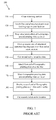
- FIG. 1 shows a conventional method of mounting a flexographic printing plate 100 with structured patterned backing tape.
- step 110 a mounting surface of the printing plate cylinder is cleaned and prepared for placement of a structured patterned backing tape.
- a first end of the structured patterned backing tape is attached to the printing plate cylinder at a seam location that is approximately 3 to 4 inches away from a scribe line, also referred to as a cut line, which runs the length of the printing plate cylinder.
- the structured patterned backing tape is wrapped around the printing plate cylinder.
- a second end of the structured patterned backing tape overlaps the first end at the seam location that is approximately 3 to 4 inches away from the scribe line of the printing plate cylinder.
- step 150 the second end of the structured patterned backing tape is cut at the seam location that is approximately 3 to 4 inches away from the scribe line of the printing plate cylinder. Because there is no cut line, it is difficult to keep the cut tight and the process of making the cut is more difficult. In the event the cut is not tight at the seam location, the gap in the structured patterned backing tape can cause printing irregularities and discontinuities.
- step 160 a first end of a flexographic printing plate is attached to the printing plate cylinder at the scribe line.
- step 170 the flexographic printing plate is wrapped around the printing plate cylinder.
- step 180 a second end of the flexographic printing plate overlaps the first end at the scribe line.
- step 190 the second end of the flexographic printing plate is cut in a tight seam such that the first end and second end of the flexographic printing plate meet at the scribe line.
- the seam location of the structured patterned backing tape is located approximately 3 to 4 inches from the scribe line so there is no overlap between the seam location of the structured patterned backing tape and the seam location of the flexographic printing plate at the scribe line. Because the seams do not overlap, the flexographic printing plate may be removed and replaced without inadvertently removing the structured patterned backing tape. In addition, the flexographic printing plate may be repositioned during initial registration without lifting the structured patterned backing tape off the printing plate cylinder when putting the flexographic printing plate in register. In the event the seams overlap, there may be liftoff during high speed print operations.
- FIG. 2 shows a flexographic printing system 200 in accordance with one or more embodiments of the present invention.
- Flexographic printing system 200 may include an ink pan 210 , an ink roll 220 (also referred to as a fountain roll), an anilox roll 230 (also referred to as a meter roll), a doctor blade 240 , a printing plate cylinder 250 , a flexographic printing plate 260 , and an impression cylinder 270 .
- Ink roll 220 transfers ink 280 from ink pan 210 to anilox roll 230 .
- Anilox roll 230 is typically constructed of a steel or aluminum core that may be coated by an industrial ceramic whose surface contains a plurality of very fine dimples, known as cells (not shown). Doctor blade 240 removes excess ink 280 from anilox roll 230 . In transfer area 290 , anilox roll 230 meters the amount of ink 280 transferred to flexographic printing plate 260 disposed on printing plate cylinder 250 to a uniform thickness.
- Printing plate cylinder 250 may be generally made of metal and the surface may be plated with chromium, or the like, to provide increased abrasion resistance.
- flexographic printing plate 260 may be attached to printing plate 250 by a structured patterned backing tape (not shown).
- flexographic printing plate 260 may be composed of a rubber or photo-polymer.
- a substrate 285 moves between the printing plate cylinder 250 and impression cylinder 270 .
- Impression cylinder 270 applies pressure to printing plate cylinder 250 , transferring an image from flexographic printing plate 260 to substrate 285 at transfer area 295 .
- the rotational speed of printing plate cylinder 250 may be synchronized to match the speed at which substrate 285 moves through the flexographic printing system 200 . In one or more embodiments of the present invention, the speed may vary between approximately 20 feet per minute to approximately 750 feet per minute.
- the flexographic printing system may use an ink suitable for printing a patterned ink seed layer on the substrate.
- the ink may be a catalytic ink that serves as a base layer capable of being electroless plated.
- the ink may be a catalytic alloy ink that serves as a base layer capable of being electroless plated.
- catalytic inks and catalytic alloy inks are within the scope of one or more embodiments of the present invention.
- the printed patterned ink seed layer includes a plurality of seed conductors suitable for electroless plating.
- the printed patterned ink seed conductors may be arranged in a micro mesh.
- the printed patterned ink seed conductors may be arranged in a micro mesh of row conductors and column conductors that are co-planar and perpendicular to one another.
- a width of the printed patterned ink seed conductors may be in a range suitable for use in touch sensors.
- a width of the printed patterned ink seed conductors may be in a range between approximately 1 micron to approximately 9 microns. In one or more embodiments of the present invention, a width of the printed patterned ink seed conductors may be in a range between approximately 10 microns to approximately 20 microns. In one or more embodiments of the present invention, a width of the printed patterned ink seed conductors may be greater than 20 microns. In one or more embodiments of the present invention, the printed patterned ink seed layers may serve as the base layers for conductors of a touch sensor after electroless plating.
- substrate 285 may be rigid. In one or more embodiments of the present invention, substrate 285 may be flexible. In one or more embodiments of the present invention, substrate 285 may be opaque. In one or more embodiments of the present invention, substrate 285 may be transparent. In one or more embodiments of the present invention, transparent means the transmission of light with a transmittance rate of 90% or more. In one or more embodiments of the present invention, substrate 285 may be polyethylene terephthalate (“PET”). In one or more embodiments of the present invention, substrate 285 may be polyethylene naphthalate (“PEN”). In one or more embodiments of the present invention, substrate 285 may be cellulose acetate (“TAC”).
- PET polyethylene terephthalate
- PEN polyethylene naphthalate
- TAC cellulose acetate
- substrate 285 may be linear low-density polyethylene (“LLDPE”). In one or more embodiments of the present invention, substrate 285 may be bi-axially-oriented polypropylene (“BOPP”). In one or more embodiments of the present invention, substrate 285 may be a polyester substrate. In one or more embodiments of the present invention, substrate 285 may be a thin glass substrate. In one or more embodiments of the present invention, substrate 285 may be a polypropylene, foam, paper, aluminum, or foil. One of ordinary skill in the art will recognize that other substrates are within the scope of one or more embodiments of the present invention.
- FIG. 3 shows a structured patterned backing tape on a printing plate cylinder 300 in accordance with one or more embodiments of the present invention.
- Printing plate cylinder 250 includes scribe line 310 along the longitude of printing plate cylinder 250 .
- Scribe line 310 is an indentation that may be used to locate the plate center of printing plate cylinder 250 and make a clean cut.
- scribe line 310 may be used as a guide to start and finish wrapping structured patterned backing tape 320 around printing plate cylinder 250 .
- scribe line 310 may be used as a guide to start placement of structured patterned backing tape 320 , which is then wrapped around printing plate cylinder 250 .
- scribe line 310 may be used as a guide to finish placement of structured patterned backing tape 320 at scribe line 310 after wrapping.
- excess structured patterned backing tape 320 may extend beyond the finish at scribe line 310 .
- the excess structured patterned backing tape 320 may be removed by making a cut on structured patterned backing tape 320 along the longitude of printing plate cylinder 250 at scribe line 310 .
- structured patterned backing tape 320 may be wrapped around printing plate cylinder 250 starting at scribe line 310 and the excess structured patterned backing tape 320 is cut along the seam at scribe line 310 without overlap or gap.
- structured patterned backing tape 320 may be wrapped around printing plate cylinder 250 in a rotational direction or across the cylinder face.
- structured patterned backing tape 320 adheres to printing plate cylinder 250 by an adhesive disposed on a first side of structured patterned backing tape 320 .
- a flexographic printing plate adheres to structured patterned backing tape 320 by an adhesive disposed on a second side of structured patterned backing tape 320 .
- structured patterned backing tape 320 may comprise ChannalBACTM structured patterned backing tape commercially available from Controlled DisplacementTM Technology LLC of Parkland, Fla.
- ChannalBACTM differs from cellular foam in that ChannalBACTM completely separates the air and elastomeric components by forming solid elastomeric channels separated by channels of air within its membrane. As such, ChannalBACTM cannot be crushed like cellular foam and resists fatigue and deformation in a spring-like manner. Because of the more uniform density and resistance when compared to cellular foam, ChannalBACTM provides a more uniform and consistent transfer of ink from the flexographic printing plate to the substrate.
- the elastomeric channels When placed on printing plate cylinder 250 , the elastomeric channels are aligned at a 45-degree angle with respect to scribe line 310 .
- impression pressure is increased, the elastomeric channels of ChannalBACTM displace in a path of least resistance, resulting in movement of the elastomer across the rotational direction of printing plate cylinder 250 .
- ChannalBACTM Because of the controlled displacement of the elastomeric channels, ChannalBACTM provides a more uniform and consistent transfer of ink from the flexographic printing plate to the substrate. In addition, because of the more even distribution of pressure, there is no need to increase impression pressure during long production runs.
- structured patterned backing tape 320 may serve as a shock absorber and cushion for use between the flexographic printing plate and printing plate cylinder during printing. In one or more embodiments of the present invention, structured patterned backing tape 320 may compensate for variations in thickness and height. In one or more embodiments of the present invention, structured patterned backing tape 320 may maintain centricity of the flexographic printing plate and printing plate cylinder. In one or more embodiments of the present invention, structured patterned backing tape 320 may prevent distortions in the image being printed from the flexographic printing plate to the substrate. In one or more embodiments of the present invention, structured patterned backing tape 320 may reduce printing plate cylinder bounce.
- FIG. 4 shows a method of mounting a flexographic printing plate with structured patterned backing tape in accordance with one or more embodiments of the present invention.
- a mounting surface of the printing plate cylinder may be cleaned and prepared for placement of a structured patterned backing tape.
- a first end of the structured patterned backing tape may be attached to the printing plate cylinder at the scribe line of the printing plate cylinder.
- the structured patterned backing tape may be wrapped around the printing plate cylinder.
- a second end of the structured patterned backing tape may overlap the first end at the scribe line of the printing plate cylinder.
- the second end of the structured patterned backing tape may be cut in a tight seam such that the first end and second end of the structured patterned backing tape meet at the scribe line of the printing plate cylinder without overlap or gap.
- a first end of a flexographic printing plate may be attached to the printing plate cylinder at a seam location that is offset from the scribe line.
- the first end of the flexographic printing plate may be attached to an 18 inch 151 tooth drum-type printing plate cylinder at a seam location that is offset approximately 4.5 inches ahead of the scribe line.
- the offset may vary in accordance with the type and dimensions of the printing plate cylinder used.
- step 470 the flexographic printing plate is wrapped around the printing plate cylinder.
- step 480 a second end of the flexographic printing plate overlaps the first end at the seam location offset and ahead of the scribe line.
- step 490 the second end of the flexographic printing plate is cut in a tight seam such that the first end and second end of the flexographic printing plate meet at the offset seam location.
- the scribe line of the printing plate cylinder may create a band in the printing area between the scribe line and the offset seam location of the flexographic printing plate. If there are embossing patterns in this area, the band may distort the printing patterns. For example, a 5 micron wide line printed in the band area may result in a printed line of 10 or more microns in width.
- the band may occur when the anilox roll hits the scribe line, giving rise to a bump that tends to distort the printing patterns located in the band area.
- the band may create irregularities or discontinuities in the printed pattern on the substrate. These irregularities or discontinuities negatively affect the integrity and function of the printed patterns on the substrate.
- the structured patterned backing tape may be aligned at the scribe line of the printing plate cylinder. In one or more embodiments of the present invention, aligning the structured patterned backing tape at the scribe line allows for quick and easy placement, removal, and replacement of the structured patterned backing tape on the printing plate cylinder. In one or more embodiments of the present invention, aligning the structured patterned backing tape at the scribe line allows for an easy cut of the structured patterned backing tape. In one or more embodiments of the present invention, the flexographic printing plate may be aligned at a seam location that is offset from the scribe line.
- the offset seam location of an 18 inch 151 tooth drum-type printing plate cylinder may be 4.5 inches ahead of the scribe line.
- aligning the flexographic printing plate at the offset seam location ahead of the scribe line hides the band in a dead zone that may not include embossing patterns.
- the seam location of the structured patterned backing tape at the scribe line and the offset seam location of the flexographic printing plate ahead of the scribe line do not overlap.
- the flexographic printing plate may be removed and replaced without inadvertently removing the structured patterned backing tape.
- a method of mounting a flexo master with structured patterned backing tape allows for flexographic printing of uniform micron-fine lines and features.
- a method of mounting a flexo master with structured patterned backing tape allows for flexographic printing of uniform micron-fine lines and features over a large area.
- a method of mounting a flexo master with structured patterned backing tape increases flexographic printing speed of uniform micron-fine lines and features over a large area.
- a method of mounting a flexo master with structured patterned backing tape reduces flexographic printing plate mounting time.
- a method of mounting a flexo master with structured patterned backing tape provides an even distribution of pressure between a flexographic printing plate and printing plate cylinder.
- a method of mounting a flexo master with structured patterned backing tape decreases printing plate cylinder bounce.
- a method of mounting a flexo master with structured patterned backing tape maintains centricity of the flexographic printing plate and printing plate cylinder.
- a method of mounting a flexo master with structured patterned backing tape extends flexographic printing plate life.
- a method of mounting a flexo master with structured patterned backing tape allows for constant impression during long production runs.
- a method of mounting a flexo master with structured patterned backing tape eliminates the need for increased impression during long production runs.
- a method of mounting a flexo master with structured patterned backing tape prevents distortions in an image transferred to a substrate
- a method of mounting a flexo master with structured patterned backing tape compensates for variations in thickness.
- a method of mounting a flexo master with structured patterned backing tape compensates for variations in height.
- a method of mounting a flexo master with structured patterned backing tape prevents tape crushing during long production runs.
- a method of mounting a flexo master with structured patterned backing tape increases flexographic printing speed.
- a method of mounting a flexo master with structured patterned backing tape improves the flexographic printing of fine lines and features having a width in a range between 1 micron and 9 microns.
- a method of mounting a flexo master with structured patterned backing tape improves the flexographic printing of fine lines and features having a width in a range between 10 microns and 20 microns.
- a method of mounting a flexo master with structured patterned backing tape improves the flexographic printing of fine lines and features having a width greater than 20 microns.
- a method of mounting a flexo master with structured patterned backing tape is compatible with existing flexographic printing processes and systems.
- a method of mounting a flexo master with structured patterned backing tape allows for the fabrication of improved touch sensors.
Abstract
Description
Claims (10)
Priority Applications (4)
| Application Number | Priority Date | Filing Date | Title |
|---|---|---|---|
| US13/784,765 US9056450B2 (en) | 2013-03-04 | 2013-03-04 | Method of mounting a flexographic printing plate with structured patterned backing tape |
| PCT/US2013/065878 WO2014137403A1 (en) | 2013-03-04 | 2013-10-21 | Method of mounting a flexographic printing plate with structured patterned backing tape |
| TW102148159A TW201434664A (en) | 2013-03-04 | 2013-12-25 | Method of mounting a flexographic printing plate with structured patterned backing tape |
| US14/252,945 US20140245914A1 (en) | 2013-03-04 | 2014-04-15 | Method of mounting a flexographic printing plate to avoid banding |
Applications Claiming Priority (1)
| Application Number | Priority Date | Filing Date | Title |
|---|---|---|---|
| US13/784,765 US9056450B2 (en) | 2013-03-04 | 2013-03-04 | Method of mounting a flexographic printing plate with structured patterned backing tape |
Related Child Applications (1)
| Application Number | Title | Priority Date | Filing Date |
|---|---|---|---|
| US14/252,945 Continuation-In-Part US20140245914A1 (en) | 2013-03-04 | 2014-04-15 | Method of mounting a flexographic printing plate to avoid banding |
Publications (2)
| Publication Number | Publication Date |
|---|---|
| US20140245913A1 US20140245913A1 (en) | 2014-09-04 |
| US9056450B2 true US9056450B2 (en) | 2015-06-16 |
Family
ID=51420260
Family Applications (1)
| Application Number | Title | Priority Date | Filing Date |
|---|---|---|---|
| US13/784,765 Expired - Fee Related US9056450B2 (en) | 2013-03-04 | 2013-03-04 | Method of mounting a flexographic printing plate with structured patterned backing tape |
Country Status (3)
| Country | Link |
|---|---|
| US (1) | US9056450B2 (en) |
| TW (1) | TW201434664A (en) |
| WO (1) | WO2014137403A1 (en) |
Cited By (3)
| Publication number | Priority date | Publication date | Assignee | Title |
|---|---|---|---|---|
| US20150122138A1 (en) * | 2012-06-11 | 2015-05-07 | Unipixel Displays, Inc. | Methods of manufacture and use of customized flexomaster patterns for flexographic printing |
| DE102017000494A1 (en) | 2017-01-20 | 2018-07-26 | Lohmann Gmbh & Co Kg | Conditioning, stripping and testing device for application-oriented simulation of the bonding of printing plates on cylindrical test substrates by means of pressure-sensitive adhesive tapes |
| US11691408B2 (en) | 2020-05-26 | 2023-07-04 | Esko Software Bv | System and method for designing and creating a printing plate |
Citations (22)
| Publication number | Priority date | Publication date | Assignee | Title |
|---|---|---|---|---|
| US4537129A (en) * | 1980-07-25 | 1985-08-27 | W. R. Grace & Co. | Offset printing blanket |
| US4589338A (en) | 1984-02-17 | 1986-05-20 | Billy Collins | Flexographic plate mounting apparatus and method |
| EP0222033A1 (en) | 1985-11-11 | 1987-05-20 | Billy Collins | Flexographic plate mounting apparatus and method |
| US5476712A (en) | 1994-05-31 | 1995-12-19 | Avery Dennison Corporation | Flexographic plate mounting tape |
| US5979315A (en) * | 1998-10-05 | 1999-11-09 | Moore U.S.A., Inc. | Flexographic printing selectively |
| EP1060884A1 (en) | 1999-06-08 | 2000-12-20 | Bieffebi S.p.A. | Mounting device for flexographic printing plates |
| US6343550B1 (en) * | 2000-01-24 | 2002-02-05 | Douglas W. Feesler | Flexographic printing apparatus and method |
| US6948429B2 (en) | 2003-03-05 | 2005-09-27 | Nhk Spring Co., Ltd. | Flexographic printing plate mounting sheet |
| US20070068404A1 (en) | 2005-09-29 | 2007-03-29 | Edwin Hirahara | Systems and methods for additive deposition of materials onto a substrate |
| US20080055581A1 (en) * | 2004-04-27 | 2008-03-06 | Rogers John A | Devices and methods for pattern generation by ink lithography |
| US20100021695A1 (en) * | 2006-12-27 | 2010-01-28 | Susumu Naoyuki | Engraved plate and substrate with conductor layer pattern using the same |
| US20100129620A1 (en) * | 2008-11-25 | 2010-05-27 | Sca Hygiene Products Ab | Apparatus and method for printing on a material for use in absorbent articles |
| US7807001B2 (en) * | 2007-06-28 | 2010-10-05 | Eastman Kodak Company | Lamination device method for flexographic plate manufacturing |
| US20100282102A1 (en) | 2009-05-08 | 2010-11-11 | Mehdizadeh Sharmin | Label printing cylinder and process |
| US20110045248A1 (en) | 2007-12-21 | 2011-02-24 | Giesecke & Devrient Gmbh | Method for producing a microstructure |
| US20110249057A1 (en) | 2006-02-21 | 2011-10-13 | Dejoseph Anthony B | Method and apparatus for transferring a principal substance and printing system |
| US20110259221A1 (en) * | 2009-01-12 | 2011-10-27 | Colin Hargreaves | Flexographic printing method and flexographic printing apparatus |
| US8071269B2 (en) | 2004-10-14 | 2011-12-06 | Donald Long | Compressible flexographic printing plate construction |
| US8252514B2 (en) | 2006-03-14 | 2012-08-28 | Day International, Inc. | Flexographic printing plate assembly |
| US8313888B2 (en) | 2008-06-11 | 2012-11-20 | Toyo Boseki Kabushiki Kaisha | Photosensitive flexographic printing original plate |
| US20120298000A1 (en) | 2010-12-03 | 2012-11-29 | E. I. Du Pont De Nemours And Company | Method for making a cylindrically-shaped element for use in printing |
| US8384691B2 (en) | 2008-02-28 | 2013-02-26 | 3M Innovative Properties Company | Touch screen sensor |
-
2013
- 2013-03-04 US US13/784,765 patent/US9056450B2/en not_active Expired - Fee Related
- 2013-10-21 WO PCT/US2013/065878 patent/WO2014137403A1/en active Application Filing
- 2013-12-25 TW TW102148159A patent/TW201434664A/en unknown
Patent Citations (23)
| Publication number | Priority date | Publication date | Assignee | Title |
|---|---|---|---|---|
| US4537129A (en) * | 1980-07-25 | 1985-08-27 | W. R. Grace & Co. | Offset printing blanket |
| US4589338A (en) | 1984-02-17 | 1986-05-20 | Billy Collins | Flexographic plate mounting apparatus and method |
| EP0222033A1 (en) | 1985-11-11 | 1987-05-20 | Billy Collins | Flexographic plate mounting apparatus and method |
| US5476712A (en) | 1994-05-31 | 1995-12-19 | Avery Dennison Corporation | Flexographic plate mounting tape |
| US6576075B1 (en) | 1994-05-31 | 2003-06-10 | Avery Dennison Corporation | Method of making and using a flexographic plate mounting tape |
| US5979315A (en) * | 1998-10-05 | 1999-11-09 | Moore U.S.A., Inc. | Flexographic printing selectively |
| EP1060884A1 (en) | 1999-06-08 | 2000-12-20 | Bieffebi S.p.A. | Mounting device for flexographic printing plates |
| US6343550B1 (en) * | 2000-01-24 | 2002-02-05 | Douglas W. Feesler | Flexographic printing apparatus and method |
| US6948429B2 (en) | 2003-03-05 | 2005-09-27 | Nhk Spring Co., Ltd. | Flexographic printing plate mounting sheet |
| US20080055581A1 (en) * | 2004-04-27 | 2008-03-06 | Rogers John A | Devices and methods for pattern generation by ink lithography |
| US8071269B2 (en) | 2004-10-14 | 2011-12-06 | Donald Long | Compressible flexographic printing plate construction |
| US20070068404A1 (en) | 2005-09-29 | 2007-03-29 | Edwin Hirahara | Systems and methods for additive deposition of materials onto a substrate |
| US20110249057A1 (en) | 2006-02-21 | 2011-10-13 | Dejoseph Anthony B | Method and apparatus for transferring a principal substance and printing system |
| US8252514B2 (en) | 2006-03-14 | 2012-08-28 | Day International, Inc. | Flexographic printing plate assembly |
| US20100021695A1 (en) * | 2006-12-27 | 2010-01-28 | Susumu Naoyuki | Engraved plate and substrate with conductor layer pattern using the same |
| US7807001B2 (en) * | 2007-06-28 | 2010-10-05 | Eastman Kodak Company | Lamination device method for flexographic plate manufacturing |
| US20110045248A1 (en) | 2007-12-21 | 2011-02-24 | Giesecke & Devrient Gmbh | Method for producing a microstructure |
| US8384691B2 (en) | 2008-02-28 | 2013-02-26 | 3M Innovative Properties Company | Touch screen sensor |
| US8313888B2 (en) | 2008-06-11 | 2012-11-20 | Toyo Boseki Kabushiki Kaisha | Photosensitive flexographic printing original plate |
| US20100129620A1 (en) * | 2008-11-25 | 2010-05-27 | Sca Hygiene Products Ab | Apparatus and method for printing on a material for use in absorbent articles |
| US20110259221A1 (en) * | 2009-01-12 | 2011-10-27 | Colin Hargreaves | Flexographic printing method and flexographic printing apparatus |
| US20100282102A1 (en) | 2009-05-08 | 2010-11-11 | Mehdizadeh Sharmin | Label printing cylinder and process |
| US20120298000A1 (en) | 2010-12-03 | 2012-11-29 | E. I. Du Pont De Nemours And Company | Method for making a cylindrically-shaped element for use in printing |
Non-Patent Citations (4)
| Title |
|---|
| International Search Report of the International Searching Authority (Korea) for corresponding international application PCT/US2013/065878 dated Feb. 3, 2014. |
| Mounting instructions D-3.PDF available at http://www.channalbac.com. |
| Unknown, Mounting instructions D-3.PDF available at http://www.channalbac.com. |
| Written Opinion of the International Searching Authority (Korea) for corresponding international application PCT/US2013/065878 dated Feb. 3, 2014. |
Cited By (6)
| Publication number | Priority date | Publication date | Assignee | Title |
|---|---|---|---|---|
| US20150122138A1 (en) * | 2012-06-11 | 2015-05-07 | Unipixel Displays, Inc. | Methods of manufacture and use of customized flexomaster patterns for flexographic printing |
| US9446578B2 (en) * | 2012-06-11 | 2016-09-20 | Eastman Kodak Company | Methods of manufacture and use of customized flexomaster patterns for flexographic printing |
| US9764542B2 (en) | 2012-06-11 | 2017-09-19 | Eastman Kodak Company | Method of flexographically printing a plurality of lines |
| DE102017000494A1 (en) | 2017-01-20 | 2018-07-26 | Lohmann Gmbh & Co Kg | Conditioning, stripping and testing device for application-oriented simulation of the bonding of printing plates on cylindrical test substrates by means of pressure-sensitive adhesive tapes |
| DE102017000494B4 (en) | 2017-01-20 | 2018-10-04 | Lohmann Gmbh & Co Kg | Conditioning, stripping and testing device for application-oriented simulation of the bonding of printing plates on cylindrical test substrates by means of pressure-sensitive adhesive tapes |
| US11691408B2 (en) | 2020-05-26 | 2023-07-04 | Esko Software Bv | System and method for designing and creating a printing plate |
Also Published As
| Publication number | Publication date |
|---|---|
| US20140245913A1 (en) | 2014-09-04 |
| TW201434664A (en) | 2014-09-16 |
| WO2014137403A1 (en) | 2014-09-12 |
Similar Documents
| Publication | Publication Date | Title |
|---|---|---|
| US9873276B2 (en) | Microcontact printing stamps with functional features | |
| US20150030984A1 (en) | Method of manufacturing a flexographic printing plate for high-resolution printing | |
| US9056450B2 (en) | Method of mounting a flexographic printing plate with structured patterned backing tape | |
| JP2015523619A (en) | Fabrication of high resolution conductive patterns using organometallic inks and striped anilox rolls | |
| JP2015523249A (en) | How to make and use flexo master patterns customized for flexographic printing | |
| US9063426B2 (en) | Method of manufacturing a flexographic printing plate with support structures | |
| US9302464B2 (en) | Inking system for flexographic printing | |
| US9132622B2 (en) | Method of printing uniform line widths with angle effect | |
| US20140349013A1 (en) | Method of manufacturing a low volume transfer anilox roll for high-resolution flexographic printing | |
| US9669617B2 (en) | Anilox roll with low surface energy zone | |
| JP2019155652A (en) | Manufacturing method of printing substrate | |
| WO2014137404A1 (en) | Method of printing intersecting lines with angle effect | |
| TWI699292B (en) | printed version | |
| WO2015060895A1 (en) | Method of mounting a flexographic printing plate to avoid banding | |
| US20150258772A1 (en) | Multi-station flexographic printing system for patterned coating deposition | |
| US11072165B2 (en) | Low-volume gravure inking system | |
| US20140245914A1 (en) | Method of mounting a flexographic printing plate to avoid banding | |
| WO2015164884A1 (en) | Multi-station flexographic printing system for patterned coating deposition | |
| US20160202811A1 (en) | Method of fabricating electrically isolated conductors using flexographic voiding | |
| US11487393B2 (en) | Method for preparing stacking structure, stacking structure and touch sensor | |
| JP2009078500A (en) | Letterpress printer and method for manufacturing high-polymer el element by using the same | |
| EP3894223B1 (en) | Low-volume flexographic and gravure inking systems | |
| US20140245909A1 (en) | Multi-station flexographic printing process and system | |
| KR101410690B1 (en) | Printing apparatus | |
| KR101619588B1 (en) | Offset printing Blanket and the combination and replacement Method enabling Surface print layer of separation |
Legal Events
| Date | Code | Title | Description |
|---|---|---|---|
| AS | Assignment |
Owner name: UNI-PIXEL DISPLAYS, INC., TEXAS Free format text: ASSIGNMENT OF ASSIGNORS INTEREST;ASSIGNORS:KENNAIR, TERRY P.;GOLDBERG, EVAN M.;REEL/FRAME:029921/0167 Effective date: 20130301 |
|
| AS | Assignment |
Owner name: HUDSON BAY FUND LP, AS COLLATERAL AGENT, NEW YORK Free format text: ASSIGNMENT FOR SECURITY PATENTS;ASSIGNORS:UNI-PIXEL, INC.;UNI-PIXEL DISPLAYS, INC.;REEL/FRAME:035469/0294 Effective date: 20150416 |
|
| STCF | Information on status: patent grant |
Free format text: PATENTED CASE |
|
| AS | Assignment |
Owner name: UNI-PIXEL, INC., CALIFORNIA Free format text: RELEASE OF SECURITY INTEREST PATENTS;ASSIGNOR:HUDSON BAY FUND LP;REEL/FRAME:038953/0230 Effective date: 20160608 Owner name: UNI-PIXEL DISPLAYS, INC., CALIFORNIA Free format text: RELEASE OF SECURITY INTEREST PATENTS;ASSIGNOR:HUDSON BAY FUND LP;REEL/FRAME:038953/0230 Effective date: 20160608 |
|
| AS | Assignment |
Owner name: WESTERN ALLIANCE BANK, CALIFORNIA Free format text: SECURITY INTEREST;ASSIGNORS:UNI-PIXEL, INC.;UNI-PIXEL DISPLAYS, INC.;REEL/FRAME:040503/0250 Effective date: 20161018 |
|
| AS | Assignment |
Owner name: FUTURE TECH CAPITAL, LLC, CALIFORNIA Free format text: ASSIGNMENT OF ASSIGNORS INTEREST;ASSIGNORS:UNI-PIXEL, INC.;UNI-PIXEL DISPLAYS, INC.;REEL/FRAME:046170/0574 Effective date: 20171108 |
|
| FEPP | Fee payment procedure |
Free format text: MAINTENANCE FEE REMINDER MAILED (ORIGINAL EVENT CODE: REM.); ENTITY STATUS OF PATENT OWNER: LARGE ENTITY |
|
| LAPS | Lapse for failure to pay maintenance fees |
Free format text: PATENT EXPIRED FOR FAILURE TO PAY MAINTENANCE FEES (ORIGINAL EVENT CODE: EXP.); ENTITY STATUS OF PATENT OWNER: LARGE ENTITY |
|
| STCH | Information on status: patent discontinuation |
Free format text: PATENT EXPIRED DUE TO NONPAYMENT OF MAINTENANCE FEES UNDER 37 CFR 1.362 |
|
| FP | Lapsed due to failure to pay maintenance fee |
Effective date: 20190616 |