US9045657B2 - Viscoelastic ink for direct writing of hydrogel structures - Google Patents

Viscoelastic ink for direct writing of hydrogel structures Download PDF

Info

Publication number
US9045657B2
US9045657B2 US13/636,542 US201113636542A US9045657B2 US 9045657 B2 US9045657 B2 US 9045657B2 US 201113636542 A US201113636542 A US 201113636542A US 9045657 B2 US9045657 B2 US 9045657B2
Authority
US
United States
Prior art keywords
ink
scaffold
concentration
polymer
hydrogel
Prior art date
Legal status (The legal status is an assumption and is not a legal conclusion. Google has not performed a legal analysis and makes no representation as to the accuracy of the status listed.)
Active, expires
Application number
US13/636,542
Other versions
US20130084449A1 (en
Inventor
Jennifer A. Lewis
Robert F. Shepherd
Robert A. Barry, III
Sara T. Parker
Jennifer N. H. Shepherd
Pierre Wiltzius
Ralph G. Nuzzo
Current Assignee (The listed assignees may be inaccurate. Google has not performed a legal analysis and makes no representation or warranty as to the accuracy of the list.)
University of Illinois
Original Assignee
University of Illinois
Priority date (The priority date is an assumption and is not a legal conclusion. Google has not performed a legal analysis and makes no representation as to the accuracy of the date listed.)
Filing date
Publication date
Application filed by University of Illinois filed Critical University of Illinois
Priority to US13/636,542 priority Critical patent/US9045657B2/en
Publication of US20130084449A1 publication Critical patent/US20130084449A1/en
Assigned to THE BOARD OF TRUSTEES OF THE UNIVERSITY OF ILLINOIS reassignment THE BOARD OF TRUSTEES OF THE UNIVERSITY OF ILLINOIS ASSIGNMENT OF ASSIGNORS INTEREST (SEE DOCUMENT FOR DETAILS). Assignors: NUZZO, RALPH G., SHEPHERD, ROBERT F., BARRY, ROBERT A., III, LEWIS, JENNIFER A., PARKER, SARA T., SHEPHERD, JENNIFER N.H., WILTZIUS, PIERRE
Application granted granted Critical
Publication of US9045657B2 publication Critical patent/US9045657B2/en
Active legal-status Critical Current
Adjusted expiration legal-status Critical

Links

Images

Classifications

    • CCHEMISTRY; METALLURGY
    • C09DYES; PAINTS; POLISHES; NATURAL RESINS; ADHESIVES; COMPOSITIONS NOT OTHERWISE PROVIDED FOR; APPLICATIONS OF MATERIALS NOT OTHERWISE PROVIDED FOR
    • C09DCOATING COMPOSITIONS, e.g. PAINTS, VARNISHES OR LACQUERS; FILLING PASTES; CHEMICAL PAINT OR INK REMOVERS; INKS; CORRECTING FLUIDS; WOODSTAINS; PASTES OR SOLIDS FOR COLOURING OR PRINTING; USE OF MATERIALS THEREFOR
    • C09D11/00Inks
    • C09D11/16Writing inks
    • AHUMAN NECESSITIES
    • A61MEDICAL OR VETERINARY SCIENCE; HYGIENE
    • A61LMETHODS OR APPARATUS FOR STERILISING MATERIALS OR OBJECTS IN GENERAL; DISINFECTION, STERILISATION OR DEODORISATION OF AIR; CHEMICAL ASPECTS OF BANDAGES, DRESSINGS, ABSORBENT PADS OR SURGICAL ARTICLES; MATERIALS FOR BANDAGES, DRESSINGS, ABSORBENT PADS OR SURGICAL ARTICLES
    • A61L27/00Materials for grafts or prostheses or for coating grafts or prostheses
    • A61L27/14Macromolecular materials
    • A61L27/16Macromolecular materials obtained by reactions only involving carbon-to-carbon unsaturated bonds
    • AHUMAN NECESSITIES
    • A61MEDICAL OR VETERINARY SCIENCE; HYGIENE
    • A61LMETHODS OR APPARATUS FOR STERILISING MATERIALS OR OBJECTS IN GENERAL; DISINFECTION, STERILISATION OR DEODORISATION OF AIR; CHEMICAL ASPECTS OF BANDAGES, DRESSINGS, ABSORBENT PADS OR SURGICAL ARTICLES; MATERIALS FOR BANDAGES, DRESSINGS, ABSORBENT PADS OR SURGICAL ARTICLES
    • A61L27/00Materials for grafts or prostheses or for coating grafts or prostheses
    • A61L27/14Macromolecular materials
    • A61L27/26Mixtures of macromolecular compounds
    • AHUMAN NECESSITIES
    • A61MEDICAL OR VETERINARY SCIENCE; HYGIENE
    • A61LMETHODS OR APPARATUS FOR STERILISING MATERIALS OR OBJECTS IN GENERAL; DISINFECTION, STERILISATION OR DEODORISATION OF AIR; CHEMICAL ASPECTS OF BANDAGES, DRESSINGS, ABSORBENT PADS OR SURGICAL ARTICLES; MATERIALS FOR BANDAGES, DRESSINGS, ABSORBENT PADS OR SURGICAL ARTICLES
    • A61L27/00Materials for grafts or prostheses or for coating grafts or prostheses
    • A61L27/50Materials characterised by their function or physical properties, e.g. injectable or lubricating compositions, shape-memory materials, surface modified materials
    • A61L27/52Hydrogels or hydrocolloids
    • AHUMAN NECESSITIES
    • A61MEDICAL OR VETERINARY SCIENCE; HYGIENE
    • A61LMETHODS OR APPARATUS FOR STERILISING MATERIALS OR OBJECTS IN GENERAL; DISINFECTION, STERILISATION OR DEODORISATION OF AIR; CHEMICAL ASPECTS OF BANDAGES, DRESSINGS, ABSORBENT PADS OR SURGICAL ARTICLES; MATERIALS FOR BANDAGES, DRESSINGS, ABSORBENT PADS OR SURGICAL ARTICLES
    • A61L27/00Materials for grafts or prostheses or for coating grafts or prostheses
    • A61L27/50Materials characterised by their function or physical properties, e.g. injectable or lubricating compositions, shape-memory materials, surface modified materials
    • A61L27/56Porous materials, e.g. foams or sponges
    • CCHEMISTRY; METALLURGY
    • C08ORGANIC MACROMOLECULAR COMPOUNDS; THEIR PREPARATION OR CHEMICAL WORKING-UP; COMPOSITIONS BASED THEREON
    • C08LCOMPOSITIONS OF MACROMOLECULAR COMPOUNDS
    • C08L33/00Compositions of homopolymers or copolymers of compounds having one or more unsaturated aliphatic radicals, each having only one carbon-to-carbon double bond, and only one being terminated by only one carboxyl radical, or of salts, anhydrides, esters, amides, imides or nitriles thereof; Compositions of derivatives of such polymers
    • C08L33/04Homopolymers or copolymers of esters
    • C08L33/06Homopolymers or copolymers of esters of esters containing only carbon, hydrogen and oxygen, which oxygen atoms are present only as part of the carboxyl radical
    • C08L33/10Homopolymers or copolymers of methacrylic acid esters
    • CCHEMISTRY; METALLURGY
    • C08ORGANIC MACROMOLECULAR COMPOUNDS; THEIR PREPARATION OR CHEMICAL WORKING-UP; COMPOSITIONS BASED THEREON
    • C08LCOMPOSITIONS OF MACROMOLECULAR COMPOUNDS
    • C08L5/00Compositions of polysaccharides or of their derivatives not provided for in groups C08L1/00 or C08L3/00
    • C08L5/08Chitin; Chondroitin sulfate; Hyaluronic acid; Derivatives thereof
    • CCHEMISTRY; METALLURGY
    • C09DYES; PAINTS; POLISHES; NATURAL RESINS; ADHESIVES; COMPOSITIONS NOT OTHERWISE PROVIDED FOR; APPLICATIONS OF MATERIALS NOT OTHERWISE PROVIDED FOR
    • C09DCOATING COMPOSITIONS, e.g. PAINTS, VARNISHES OR LACQUERS; FILLING PASTES; CHEMICAL PAINT OR INK REMOVERS; INKS; CORRECTING FLUIDS; WOODSTAINS; PASTES OR SOLIDS FOR COLOURING OR PRINTING; USE OF MATERIALS THEREFOR
    • C09D11/00Inks
    • C09D11/02Printing inks
    • C09D11/10Printing inks based on artificial resins
    • C09D11/101Inks specially adapted for printing processes involving curing by wave energy or particle radiation, e.g. with UV-curing following the printing
    • YGENERAL TAGGING OF NEW TECHNOLOGICAL DEVELOPMENTS; GENERAL TAGGING OF CROSS-SECTIONAL TECHNOLOGIES SPANNING OVER SEVERAL SECTIONS OF THE IPC; TECHNICAL SUBJECTS COVERED BY FORMER USPC CROSS-REFERENCE ART COLLECTIONS [XRACs] AND DIGESTS
    • Y10TECHNICAL SUBJECTS COVERED BY FORMER USPC
    • Y10TTECHNICAL SUBJECTS COVERED BY FORMER US CLASSIFICATION
    • Y10T428/00Stock material or miscellaneous articles
    • Y10T428/249921Web or sheet containing structurally defined element or component

Definitions

  • the present disclosure is related generally to polymer-based ink systems and more particularly to viscoelastic ink systems employed for direct ink writing of hydrogel structures.
  • Three-dimensional structures with micron-scale features have many potential applications, including photonic band gap materials, tissue engineering scaffolds, biosensors, and drug delivery systems. Consequently, several assembly techniques for fabricating complex three-dimensional structures with features smaller than 100 microns have been developed, such as microfabrication, holographic lithography, two-photon polymerization and colloidal self-assembly. However, all these techniques have limitations that reduce their utility.
  • Two-photon polymerization is capable of creating three-dimensional structures with sub-micron features, but from precursors that are not biocompatible and at a very slow rate, ca. ⁇ 10 ⁇ m/s.
  • Many techniques have been developed to fabricate three-dimensional photonic crystals, but they rely on expensive, complicated equipment or time-consuming procedures. Colloidal self-assembly has also been utilized to make three-dimensional periodic structures, but controlling the formation of defects is difficult.
  • Spiders for example, derive their silk fibers from a concentrated protein biopolymer solution that solidifies as it is drawn to form an extremely strong filament.
  • the extensional flow of the solution aligns liquid crystal sheets in the polymer, and the solution gels by adding ions as it leaves the spinneret. This process may be artificially recreated by the deposition of the recombinant spider silk biopolymer into a polar “deposition bath” to produce filament fibers with comparable properties.
  • Hydrogels are an important class of soft materials that can be fabricated in the form of three-dimensional (3D) microperiodic structures by colloidal templating or interference lithography.
  • 3D three-dimensional
  • tissue-engineering scaffolds are typically composed of synthetic or natural polymers and provide a means for tissue to grow outside the body.
  • the scaffolds may be biodegradable or non-biodegradable.
  • a challenge in the field is to select or design a scaffold material for cell growth and differentiation that has desirable properties, including mechanical strength, durability, and biocompatibility, and which does not induce an immune response.
  • a viscoelastic ink for direct writing of hydrogel structures and an improved hydrogel scaffold are described, and a method of making the hydrogel scaffold is also set forth.
  • Several model ink systems are shown to have excellent 3D-writing capabilities and also cytocompatibility with several types of cells, including mouse 3T3 fibroblasts, rat primary hippocampal neurons and human primary embryonic stem cells.
  • the ability to create hydrogel scaffolds with microscale features in both planar and 3D forms may open a new avenue for tailoring scaffolds for tissue engineering and other applications.
  • the viscoelastic ink includes a long chain polymer and a photopolymerizable moiety, which may be a photopolymerizable monomer or a photopolymerizable group attached to the long chain polymer.
  • the ink may also include a crosslinking agent, a photoinitiator, and water.
  • the long chain polymer is present at a concentration above a critical overap concentration c* of the long chain polymer in the ink.
  • the concentration of the long chain polymer may be 5-100 times greater than the critical overlap concentration c*.
  • the hydrogel scaffold includes a framework of interconnected rods arranged in one or more layers, where the rods are defined by one or more hydrogel filaments.
  • Each layer of the framework includes a spacing between adjacent rods of between about 1 micron and about 100 microns.
  • the one or more hydrogel filaments have a pre-polymerized structure and a post-polymerized structure, where the post-polymerized structure comprises a shear elastic modulus G′ 2 at least two orders of magnitude greater than a shear elastic modulus G′ 1 of the pre-polymerized structure.
  • the method includes forming an ink comprising a long chain polymer and a photopolymerizable moiety, extruding the ink through a micronozzle to form an extruded filament, photopolymerizing the extruded filament; and depositing the extruded filament in a pattern on a substrate to form a hydrogel scaffold.
  • the photopolymerization may be carried out before or after deposition of the extruded filament on the substrate.
  • FIG. 1( a ) is a schematic illustration of direct writing of a hydrogel-based ink through a gold-coated deposition micronozzle that is simultaneously photopolymerized via ultraviolet (UV) illumination;
  • UV ultraviolet
  • FIG. 1( b ) is an optical image of a 3D hydrogel scaffold acquired during direct ink writing (scalebar is 200 ⁇ m);
  • FIG. 2( a ) shows shear elastic (G′) and loss (G′) moduli as a function of polymerization time for an exemplary ink composed of acrylamide, glycerol, and water;
  • FIG. 2( b ) shows specific and relative viscosity of dilute polymer solutions of varying polyacrylamide (pAM) concentration
  • FIG. 2( c ) shows apparent viscosity as a function of shear rate for the final pAM hydrogel-based ink
  • FIG. 2( d ) shows shear elastic and loss moduli as a function of shear stress for the final pAM hydrogel-based ink
  • FIG. 3( a ) is a scanning electron micrograph of a 1D pAM scaffold composed of 5 ⁇ m filaments with a 20 ⁇ m center-to-center spacing;
  • FIG. 3( b ) is a 3D micro-periodic pAM hydrogel scaffold (4-layers) composed of 5 ⁇ m filaments with a 20 ⁇ m center-to-center spacing;
  • FIG. 3( c ) is a 3D micro-periodic pAM hydrogel scaffold (6-layers) composed of nominally 1 ⁇ m filaments with a 5 ⁇ m center-to-center spacing (Note: Inset in 3 ( c ) shows a higher magnification, tilted view of this scaffold and the scalebars are 50 ⁇ m (a-c), and 6 ⁇ m (inset), respectively);
  • FIGS. 4( a )- 4 ( c ) are optical fluorescence micrographs of 3T3 fibroblasts plated on the 4 ( a ) flat glass control, 4 ( b ) 1D microperiodic pAM hydrogel scaffold, and 4 ( c,d ) 3D microperiodic pAM hydrogel scaffolds (4-layers);
  • FIG. 4( d ) is a higher magnification view of 4 ( c ) demonstrating the interaction between neighboring cells, where rhodamine-phalloidin stains the actin red, DAPI stains the (DNA) nucleus blue, and the hydrogel scaffolds fluoresce green through the incorporation of fluorescein-o-acrylate (scalebars are 100 ⁇ m (a-c) and 20 ⁇ m (d), respectively);
  • FIGS. 5( a )- 5 ( d ) are SEM micrographs of 3D poly(2-hydroxyethyl methacrylate) (pHEMA) scaffolds of varying architecture that possess a center-to-center separation distance between patterned filaments of (a) 30 ⁇ m, (b) 40 ⁇ m, (c) 60 ⁇ m, and (d) 80 ⁇ m, where all scale bars are 20 ⁇ m;
  • pHEMA 3D poly(2-hydroxyethyl methacrylate)
  • FIGS. 6( a )- 6 ( c ) are confocal images (x-y scans, tiled) of primary rat hippocampal neuron cells distributed within 3D pHEMA scaffolds of varying pitch: (a) 30 ⁇ m, (b) 40 ⁇ m, (c) 60 ⁇ m, and (d) 80 ⁇ m, where a primary monoclonal antibody for actin is used to label the processes, and TO-PRO3 is used to label nuclei; side view reconstructions denote the positions (in x-z plane) of the neuronal somata, while their relative size indicates their position along the y-axis (scale bar, 40 ⁇ m);
  • FIGS. 7( a )- 7 ( b ) show neuron cell distribution as a function of (a) lateral and (b) vertical position within 3D pHEMA scaffolds of varying architecture;
  • FIGS. 8( a )- 8 ( d ) show confocal images of representative neuron cells on the 3D pHEMA scaffolds (top row), reconstructed views (middle row) and reconstructed view of cells only (bottom row) including (a) pyramidal soma morphology on scaffold (60 ⁇ m pitch), (b) neuronal process wrapping around cylindrical feature within scaffold (60 ⁇ m pitch), (c) soma supported by neuronal processes on scaffold (40 ⁇ m pitch), (d) process contact guidance on a scaffold (30 ⁇ m pitch) (scale bar, 20 ⁇ m);
  • FIGS. 9( a )- 9 ( b ) show planar representations of 3D fast Fourier transform (FFT) calculated for (a) 3D pHEMA scaffold with 40 ⁇ m pitch and (b) corresponding neuronal processes on this scaffold, where the inset in (a) is an SEM image that indicates scaffold orientation;
  • FFT fast Fourier transform
  • FIGS. 9( c )- 9 ( d ) show normalized intensity as a function of angle for (c) scaffolds of varying pitch and (d) neuronal processes calculated from the FFTs;
  • FIG. 9( e ) shows the extent of cellular process alignment as a function of scaffold pitch
  • FIG. 9( f ) shows line scans of intensity measured across the primary angle of the neuronal process alignment in the FFTs (denoted by arrows in FIG. 9( b )) (scale bar, 20 ⁇ m);
  • FIGS. 10( a )- 10 ( c ) show fluorescent micrographs of the 3D pHEMA scaffolds after exposure to (a) FITC-polylysine, (b) FITC-Protein A and (c) FITC-IgG, indicating that only polylysine is strongly absorbed by these structures (scale bar, 200 ⁇ m);
  • FIGS. 11( a )- 11 ( d ) show low magnification (tiled) confocal images of primary rat hippocampal cells interacting with 3D pHEMA scaffolds of varying pitch: (a) 30 ⁇ m, (b) 40 ⁇ m, (c) 60 ⁇ m, and (d) 80 ⁇ m, which highlight significant neuronal integration throughout each scaffold.
  • actin in the cytoskeleton is stained green, while the cell nuclei are stained red (scale bar, 100 ⁇ m);
  • FIGS. 12( a )- 12 ( b ) are reconstructed tiled, confocal images that highlight staining for the neuronal marker MAP2 (shown in green) for 3D pHEMA scaffolds with (a) 40 ⁇ m and (b) 80 ⁇ m pitch (scale bar, 40 ⁇ m);
  • FIG. 13 is a reconstructed confocal image of neurons in 3D scaffold of 30 ⁇ m pitch, which highlights the tendency for neuronal somata (marked by nuclei labeled in red) to insert themselves into the interacting regions between scaffold rods (red) (scale bar, 10 ⁇ m);
  • FIGS. 14( a )- 14 ( d ) show hydrogel scaffolds formed from 35 wt. % pHEMA with a 5:2 ratio of 300 k and 1M g/mol polymers;
  • FIGS. 15( a )- 15 ( b ) show shear viscosity and elastic modulus (G′) as a function of polymer concentration for 300,000 and 1,000,000 MW pHEMA solutions and the pHEMA ink of FIGS. 14( a )- 14 ( d );
  • FIGS. 16( a )- 16 ( b ) show (a) ratio of high shear viscosity (100 1/s) to low shear viscosity as a function of polymer concentration and (b) shear thinning behavior for the same pHEMA ink;
  • FIGS. 17( a )- 17 ( b ) show the pHEMA ink elasticity as a function of (a) monomer concentration and (b) temperature;
  • FIGS. 18( a )- 18 ( b ) show the influence of crosslinker concentration on the cured pHEMA's elastic properties
  • FIG. 19 shows printing of a 10 wt. % 300,000 Mw poly(hyaluronic) (pHA) system in 50% glycerol, 50% PBS with a 30 micron tip at a write speed of 750 microns/second;
  • pHA poly(hyaluronic)
  • FIG. 20 shows oscillatory rheology for the pHA system of FIG. 19 , specifically G′ and G′′ (elastic modulus and viscous modulus, respectively) as a function of shear stress;
  • FIG. 21 shows a structure obtained using 10 wt. % pHA, 8 wt. % PEGDA in a 50% glycerol-50% PBS solution, and FIGS. 22 and 23 provide rheological data for the system;
  • FIGS. 24( a )- 24 ( b ) show the rheology of another blended pHA-PEGDA ink system
  • FIG. 25 is an optical micrograph showing the as-printed structure of the pHA-PEGDA system of FIGS. 24( a )- 24 ( b ) prior to UV exposure;
  • FIGS. 26( a )- 26 ( c ) are SEM images depicting the fabricated hydrogel scaffolds following UV exposure and drying of the as-printed structure of FIG. 25 ;
  • FIGS. 27( a )- 27 ( b ) show cell culture results after two days for the hydrogel scaffolds of FIGS. 26( a )- 26 ( c ).
  • Viscoelastic “inks” designed to have dynamic and mechanical properties suited for printing three-dimensional (3D) hydrogel architectures are described herein.
  • the viscoelastic inks may be applied to a substrate to create planar or 3D hydrogel scaffolds of predetermined dimensions, geometry, and microperiodicity.
  • Direct ink writing is a layer-by-layer assembly technique that allows scaffolds to be formed with lateral feature sizes that are at least an order of magnitude smaller than those achieved by ink-jet printing and other rapid prototyping approaches and nearly comparable in size to those produced by two-photon polymerization and interference holography.
  • the inventive viscoelastic inks can be printed directly in air, where they undergo solidification via photopolymerization.
  • the resulting hydrogel scaffolds may be tailored for use as tunable optical sensors, stimuli-responsive soft materials, and tissue engineering scaffolds.
  • the hydrogel scaffolds may be dissolved in vivo or chemically cross-linked to provide permanent cellular support.
  • a direct ink writer that includes a 3-axis micropositioning stage and a syringe for housing the ink mounted on the micropositioning stage may be employed to form the hydrogel scaffolds.
  • the ink is extruded through the tip of a tapered micro-capillary nozzle to form a hydrogel filament that is deposited onto a stationary substrate (e.g., a glass substrate).
  • the extrusion occurs at a predetermined pressure and deposition speed.
  • the nozzle is incrementally raised in the z-direction to generate the next layer. This process is repeated until the desired 3D structure is formed.
  • 3D periodic scaffolds composed of a simple tetragonal geometry, for example, can be assembled by patterning an array of parallel filaments in the x-y plane such that their orientation is orthogonal to the layers immediately above and below a given layer.
  • Photocuring with ultraviolet (UV) light may be carried out as the filament exits the nozzle or after deposition of the filament on the substrate.
  • the viscoelastic inks extruded through the micronozzle preferably include a long chain polymer and a photopolymerizable moiety, which may be a photopolymerizable monomer or a photopolymerizable group attached to the long chain polymer.
  • the inks may also include a crosslinking agent, a photoinitiator, and water.
  • the long chain polymer is present at a concentration in the ink sufficient to be physically entangled, that is, at a concentration well above the dilute-to-semidilute transition c* of the long chain polymeric species in the ink, where
  • the concentration of the long chain polymer may be at least about 5 times greater than the critical overlap concentration c*, or at least about 10 times greater than the critical overlap concentration c*.
  • the concentration of the long chain polymer may also be at least about 100 times greater than the critical overlap concentration c*.
  • the long chain polymer may be, for example, polyacrylamide (pAM), poly(2-hydroxyethyl methacrylate) (pHEMA), poly(hyaluronic acid) (pHA), poly(N-isopropylacrylamide) (PNIPAAm), poly(ethylene oxide)/polyethylene glycol diacrylate, poly(vinyl alcohol), PLA/PGA/PLGA, block copolymers such as poloxamers (e.g., Pluronics®), polyphosphazene, alginate derivatives, or collagen derivatives.
  • the concentration of the long chain polymer in the ink is about 5 wt. % or greater, about 10 wt. % or greater, or about 20 wt. % or greater.
  • the concentration may lie between about 5 wt. % and about 50 wt. % depending on the molecular weight of the long chain polymer.
  • the viscoelastic inks may include a photopolymerizable monomer, such as monomeric acrylamide or hydroxyethyl methacrylate in the case of inks based on pAM or pHEMA, respectively.
  • a photopolymerizable monomer such as monomeric acrylamide or hydroxyethyl methacrylate in the case of inks based on pAM or pHEMA, respectively.
  • the monomer forms a chemically crosslinked polymer network that penetrates the physically entangled polymer chains.
  • the monomer may be present in the ink at a concentration in the range of from about 25 wt. % to about 55 wt. %.
  • Other inks, such as those based on pHA may include long chains of the polymer chemically modified with photopolymerizable groups (e.g., methacrylate groups) that allow the chains to participate in the crosslinking when photocured.
  • the long chain polymer generally comprises polymer chains having a molecular weight of at least about 300,000. The molecular weight may also be at least about 500,000.
  • the long chain polymer may include a multimodal (e.g., bimodal) distribution of molecular weights.
  • the long chain polymer may include first polymer chains having a first molecular weight (e.g., in the range from about 300,000 to about 500,000) and second polymer chains having a second molecular weight (e.g., in the range of from about 1,000,000 to about 1,500,000).
  • the concentration of the first polymer chains in the ink may be the same as or different from that of the second polymer chains.
  • the concentration of the first polymer chains in the ink may be higher than the concentration of the second polymer chains, which have a molecular weight of 1,000,000.
  • the concentrations are 25 wt. % and 10 wt. % for the first and second polymer chains, respectively.
  • a given viscoelastic ink may be used with a variety of nozzle diameters.
  • the ink is extruded through the micro-capillary nozzle under an applied pressure of between about 60 kPa and about 600 kPa at a deposition speed ranging from about 50 ⁇ m ⁇ s ⁇ 1 to about 500 ⁇ m ⁇ s ⁇ 1 .
  • the applied pressure may be between about 100 kPa and about 500 kPa, or between about 200 kPa and about 400 kPa
  • the deposition speed may range from about 100 ⁇ m ⁇ s ⁇ 1 to about 400 ⁇ m ⁇ s ⁇ 1 , or from about 200 ⁇ m ⁇ s ⁇ 1 to about 300 ⁇ m ⁇ s ⁇ 1
  • the micro-capillary nozzle generally has a tip diameter ranging from about 1 micron to about 100 microns in size.
  • the nozzle (tip) diameter may be between about 1 micron and about 50 microns, or between about 5 microns and about 10 microns.
  • the ink may be extruded through the micronozzle at a shear rate of at least about 10 s ⁇ 1 , or at least about 100 s ⁇ 1 . Due to the viscoelastic nature of the polymers, the ink exhibits a high viscosity at a low shear rate (e.g., about 0.1 s ⁇ 1 or less) and a substantially reduced viscosity during the extrusion through the micronozzle. The viscosity may reduced by an order of magnitude or more during the extrusion, a phenomenon referred to as “shear-thinning” behavior. For example, the viscosity of the ink during extrusion may be about 20 Pa ⁇ s or less compared to about 1,000 Pa ⁇ s at a low shear rate.
  • the extruded filament(s) are patterned to form the hydrogel scaffold, which may have a single or multilayer structure made up of interconnected rods.
  • the rods typically have a width (or diameter) in the range of from about 1 micron to about 10 microns and a spacing (or pitch) in the range of from about 5 microns to about 100 microns.
  • the pitch may be between about 1 micron and about 100 microns, between about 10 microns and about 80 microns, or between about 20 microns and about 60 microns.
  • scaffolds formed by direct ink writing include from 1 to 20 or more layers.
  • the scaffold may be periodic in one dimension, in two dimensions, or in three dimensions.
  • the extruded hydrogel filament Due to the in-situ or post-deposition photocuring step, the extruded hydrogel filament has a pre-polymerized structure and a post-polymerized structure, each of which may have different elastic properties.
  • the pre-polymerized structure of the hydrogel filament includes a physically entangled polymer network with no chemically crosslinked polymer chains. This physical gel structure exhibits elastic and viscous behavior that is well suited for extrusion through the micronozzle.
  • the post-polymerized structure of the hydrogel filament may include a physically entangled polymer network and a chemically crosslinked polymer network.
  • an ink including a long chain polymer as well as a photopolymerizable monomer may be transformed by photocuring to have an interpenetrating physical and chemical gel structure.
  • the post-polymerized structure may include a chemically crosslinked polymer network with no physically entangled polymer chains. This structure may result from photocuring of an ink containing a physically entangled long chain polymer that has been chemically modified to include photopolymerizable groups along its backbone; as a result, the long chain polymer itself participates in the cross-linking and the physical gel structure is transformed to a chemical gel structure during photocuring.
  • the post-polymerized structure of the hydrogel filament may include only a physically entangled polymer network with no chemical crosslinks.
  • the elastic properties of the starting sol-gel ink and the extruded hydrogel filament may be similar, and relatively weak scaffolds may be prepared.
  • Such scaffolds may be ideal for differentiation of primary stem cells into neuronal cells, for example.
  • the post-polymerized structure of the hydrogel filament(s) may exhibit a shear elastic modulus G′ 2 that is at least two orders of magnitude greater than the shear elastic modulus G′ 1 of the pre-polymerized structure.
  • the shear elastic modulus G′ 2 may also be at least three orders of magnitude greater than the shear elastic modulus G′ 1 .
  • Such an increase in the stiffness of the filaments prevents or minimizes deformation (e.g., sagging or collapse) of the resulting hydrogel scaffold.
  • This enhanced stiffness may be obtained from polymerized hydrogel filaments that include either or both physically entangled and chemically cross-linked polymer chains, as supported by various elasticity data described below.
  • UV radiation having a wavelength in the range of from 250 nm to 400 nm is employed for photopolymerization, and the intensity of the radiation generally lies in the range of from about 50 mW/cm 2 to about 400 mW/cm 2 .
  • the ink may be polymerized by another means (e.g., chemicals, heat, etc.)
  • the hydrogel scaffold may be chemically treated (if needed) to render the scaffold compliant for tissue growth.
  • the hydrogel scaffold may be immersed in a polylysine solution.
  • cells such as 3T3 murine fibroblasts, primary rat hippocampal neurons and human embryonic stem cells may be plated onto one-, two- and four-layer hydrogel scaffolds, as described below, to demonstrate their biocompatibility and potential suitability for tissue engineering applications.
  • One approach to creating a viscoelastic pAM ink includes first mixing monomeric acrylamide, glycerol, and water. Upon ageing for several hours under ambient conditions, the monomeric species polymerize to yield a gel composed of 30 wt. % polyacrylamide. (Alternatively, high molecular weight polyacrylamide chains can be mixed directly with monomer to create the ink.) 1 HNMR reveals that peaks associated with acrylamide, which are present initially, disappear after polymerization, followed by the emergence of two new peaks that correspond to alkyl chains (data not shown).
  • this polymerized mixture is diluted by adding monomeric acrylamide, a crosslinking agent, N,N methylene bisacrylamide, a photoinitiator, diethoxyacetophenone, and deionized water at weight ratios (w/w) of 0.480, 0.036, 0.004, and 0.480, respectively.
  • the initial polymerization step could be eliminated simply by adding high molecular weight polyacrylamide chains ( ⁇ 10 6 g/mol) directly to this photopolymerizable solution.
  • the final ink formulation exhibits pronounced shear thinning behavior, which facilitates its flow through fine deposition nozzles (see FIG. 2( c )).
  • shear thinning behavior For example, when the ink is printed through a 5 ⁇ m nozzle at 0.5 mm s ⁇ 1 , which corresponds to an estimated shear rate of 100 s ⁇ 1 , its viscosity is approximately 10 Pa ⁇ s. Under these conditions, the ink viscosity is nearly three orders of magnitude smaller than that observed at low shear rates 0.1 s ⁇ 1 ).
  • its shear elastic modulus decreases by about an order of magnitude to ⁇ 3 ⁇ 10 3 Pa relative to its initial state (see FIG. 2( d )).
  • the printed ink filament is advantageously further stiffened to prevent subsequent deformation, which occurs when the build times exceed several minutes.
  • the direct writing process may be modified by mounting a fiber optic guide onto the printhead, which facilitates in-situ photopolymerization of the ink after it exits the gold-coated micronozzle (see FIG. 1( a )).
  • the metallic coating prevents the ink from prematurely cross-linking within the glass nozzle due to UV illumination, thereby avoiding clogging during the printing process.
  • hydrogel scaffolds with precisely defined filament diameter, spacing, number of layers, and geometry may be patterned.
  • hydrogel scaffolds composed of 5 ⁇ m filaments with a 20 ⁇ m spacing between filaments with 1-4 layers and a total area of 5 mm 2 (see. FIG. 3( a ) and FIG. 3( b )) are created.
  • hydrogel scaffolds are printed with nominally 1 ⁇ m filaments with 5 ⁇ m spacing between filaments and 6 layers with a total area of 1 mm 2 , as shown in FIG. 3( c ).
  • the hydrogel scaffolds are patterned in a face-centered tetragonal structure, in which the individual filaments are observed to span distances approximately five times their diameter with minimal deflection (see FIG. 3( c ), inset).
  • 3T3 murine fibroblast cells are plated onto a flat glass substrate (control) as well as 1D and 3D microperiodic hydrogel scaffolds.
  • Poly-d-lysine is absorbed into the hydrogel scaffold network prior to cell seeding to enhance their cytocompatibility.
  • the fibroblasts plated on the control substrate display the typical flattened out morphology of cells typically seen in planar in vitro cultures, as shown in FIG. 4( a ).
  • cell interactions with patterned features and the underlying glass substrate result in their alignment along the patterning direction of the 1D microperiodic hydrogel scaffolds, as shown in FIG. 4( b ).
  • This type of elongated morphology is similar to that observed by Zhang, et al. (S. Zhang et al., Biomaterials, 1999, 20, 1213) in which murine fibroblasts formed aligned cell arrays on 1D periodic patterned surfaces that were biofunctionalized by microcontact printing of a self-assembling oligopeptide monolayer.
  • atypical fibroblast morphology was observed in response to the 3D microperiodic hydrogel scaffolds (see FIGS. 4( c ) and 4 ( d )), in which fibroblast cells integrate themselves into the regions between interconnecting hydrogel filaments. Typically one, or at most two, cell(s) reside in this space between filaments, essentially compartmentalizing themselves.
  • the ink is initially formed by mixing 1 ml deionized water (Milli-Q, Millipore), 5 g of glycerol (Sigma Aldrich) and 3.5 g acrylamide (Acros). These constituents are magnetically stirred at 30° C. until the acrylamide fully dissolves. In the quiescent state, this solution undergoes spontaneous polymerization within hours to days. If the polymerization is slow, 0.1 M MgCl 2 can be added as a catalyst. After this process is complete, 2 ml of deionized water (Milli-Q, Millipore) are added to this highly viscous solution.
  • deionized water Milli-Q, Millipore
  • a separate solution is produced by mixing 5 ml deionized water (Milli-Q, Millipore), 5 g acrylamide (Acros), 0.3 g methylene bisacrylamide (MP Biomedicals), 0.04 ml diethoxyacetophenone (Acros), and 0.018 g Fluorescein O-acrylate (Sigma Aldrich). 2 ml of this second solution are added in 0.5 ml aliquots to polymerized solution until the desired rheological properties are attained. Note, the fluorescently-labeled monomor is incorporated to facilitate direct imaging of the patterned scaffolds after cell culture is complete.
  • 1 HNMR measurements are carried out on a Varian Unity 400.
  • the sample is prepared identically to the initial ink formulation; however D 2 O is substituted for deionized water to generate an improved signal with better alignment.
  • D 2 O is substituted for deionized water to generate an improved signal with better alignment.
  • 1 ml D 2 O, 5 g of glycerol (Sigma Aldrich) and 3.5 g acrylamide (Acros) are mixed together in solution. These constituents are magnetically stirred at 30° C. until the acrylamide fully dissolves. Samples are analyzed prior to and post polymerization with NUTS (Acorn NMR) software package.
  • Oscillatory rheometry is performed on the initial ink solution using a cup and bob geometry at a frequency of 1 Hz and shear stress of 1 Pa. Oscillatory rheometry is also performed on the final ink mixture at 1 Hz at a shear rate range from 0 to 200 s ⁇ 1 to determine the elastic modulus (G′), loss modulus (G′), and yield stress ( ⁇ y ) of the printable ink. Viscometry is performed on the final ink mixture, from shear rates of 0 to 200 s ⁇ 1 . All data is taken using a cup and bob geometry (C15; Bohlin) with 3 cc of material on a Bohlin CVOR controlled-stress rheometer.
  • Capillary rheology is performed by first dissolving the initial ink solution after polymerization is completed in water and then precipitating the polyacrylamide by immersion in ethanol.
  • the monomeric acrylamide and glycerol are soluble in ethanol, while poly(acrylamide) is not. This process is repeated several times while concomitantly ultrasonicating the solution to facilitate dissolution.
  • the precipitated polymer is then dissolved at varying concentrations in an aqueous solution containing 0.50 M NaCl.
  • the relative and specific viscosities of these diluted polymer solutions are then measured, as a function of flow time, in an Ubbelholde viscometer in a constant temperature bath held at 26.5 ⁇ 0.2° C.
  • the intrinsic viscosity is determined by measuring the flow values at different concentrations and using both the Huggins (Eq. 1) and Kraemer (Eq. 2) relationships:
  • ⁇ s is the solvent viscosity
  • is the apparent viscosity
  • c is the polymer concentration
  • k H is the Huggins coefficient
  • Micropipette tips (World Precision Instruments) with diameters ranging from 1 to 10 ⁇ m are coated with a thin gold film (200 nm thick) to prevent photopolymerization of the ink prior to exiting the deposition nozzle.
  • the micropipettes are mounted onto a rotating holder to ensure an even coverage and coated inside a metal evaporator (Denton Vacuum DV-5024). Coverslip substrates are cleaned in piranha (sulfuric acid, hydrogen peroxide) solution for 1 h, rinsed with deionized water, and dried with nitrogen.
  • piranha sulfuric acid, hydrogen peroxide
  • Coverslips are placed in a 98% toluene (Fisher Scientific), 2% 3-(trimethoxysilyl)propyl methacrylate (Acros) solution for 18 hours at 60° C.
  • the slides are removed just prior to drawing, rinsed with isopropanol, and dried.
  • the ink is loaded into a syringe, with an attached gold-coated tip in place.
  • ink flow is initiated by applying a pressure of 70-80 psi. After the flow has begun, the pressure is reduced to 20-30 psi and the patterning is initiated.
  • the printed scaffolds are defined by filament width, spacing between filaments, total patterned area, number of layers, and their geometry.
  • the printed hydrogel scaffolds are soaked in deionized water (Milli-Q, Millipore) for 3 days prior to cell culture to leach out glycerol and any unpolymerized acrylamide.
  • Reflected light optical microscopy (IX71; Olympus) is performed prior to cell plating to ensure structural integrity of the scaffolds.
  • SEM micrographs are obtained with a Philips XL30 ESEM-FEG; structures are dried and sputter-coated with gold prior to imaging.
  • the interaction of murine NIH/3T3 fibroblast cells with the printed hydrogel scaffolds are investigated to assess their cytocompatibility.
  • the initial cell stock (density of ⁇ 1 ⁇ 10 6 cells/ml) is divided between three T-75 cell culture flasks, to which 20 ml of cell media (Dulbecco's Modified Eagle Medium, DMEM) that consists of 4.5 g/L glucose, 4 mM glucose, 1 mM sodium pyruvate, 1.5 g/L sodium bicarbonate and supplemented with 10% fetal bovine serum (FBS, Colorado Serum Company) and 100 U/ml penicillin/100 ⁇ g/ml streptomycin (Sigma Aldrich) is added.
  • the media is exchanged the next day to remove excess dimethyl sulfoxide (DMSO, Sigma Aldrich).
  • DMSO dimethyl sulfoxide
  • Hydrogel scaffolds are sterilized prior to cell plating, through UV light exposure in the laminar flow hood for 20 min. Scaffolds are immersed in 100 ⁇ g/ml poly-d-lysine (Sigma Aldrich) for 60 min prior to seeding. Flat glass coverslips are also evaluated as controls. Cells are plated onto the scaffolds at approximately 0.5 ⁇ 10 6 cells/ml and allowed to proliferate for approximately 48 h. After 2 days in culture, the fibroblasts are rinsed 3 times with PBS, immersed in 4% paraformaldehyde at room temperature for 10 min and then rinsed again with PBS.
  • poly-d-lysine Sigma Aldrich
  • a PBS solution containing 0.25% Triton X-100 is placed on the cells for 3 min to permeate their membranes and then the samples are rinsed again with PBS.
  • the cells are then incubated in 1% bovine serum albumin (BSA, Sigma Aldrich) in PBS for 10 min.
  • BSA bovine serum albumin
  • the cells are then incubated for an additional 20 min in a rhodamine-phalloidin (Invitrogen Molecular Probes) solution diluted 1:200 in 1% BSA solution, and again rinsed with PBS.
  • the samples are incubated with 0.002% DAPI in PBS (4′,6-diamidino-2-phenylindole, Invitrogen Molecular Probes) for 1 min and rinsed with deionized water.
  • the rhodamine-phalloidin stains actin filaments red, while the DAPI stains the DNA in the nucleus blue. All fluorescent microscopy is performed using the Zeiss Axiovert 200M inverted microscope.
  • a Dapi/Hoechts/AMCA filter (Chroma Technology) is used for the DAPI imaging, a Special Yellow Rhodamine/Cy3/Texas Red filter (Chroma Technology) is used for the rhodamine imaging and the Piston GFP filter is used for imaging the autofluorescence in the hydrogel scaffold.
  • HEMA Poly(2-hydroxyethyl methacrylate) scaffolds with varying 3D microperiodic architecture are created by direct-write assembly, and then rendered growth compliant for primary rat hippocampal neurons by absorption of polylysine. Neuronal cells thrive on these 3D scaffolds, forming differentiated, intricately branched networks. Confocal laser scanning microscopy reveals that both cell distribution and extent of neuronal process alignment depend upon scaffold architecture.
  • Mammalian tissues are composed of intricate matrices of individual cells that receive complex cues from their three-dimensional (3D) environment. Yet standard cell culture methods rely on two-dimensional (2D) substrates that are poor mimics of real tissue environments. This deficiency is especially relevant to brain tissue, where neurons exchange critical information across synapses and the 3D organization of neurons and their supporting cells is critical for function. It is well known that neuronal cells, among others, are strongly influenced by their surrounding microenvironment; for example, process orientation is guided by both topographical and chemical cues. Most prior studies of neuronal cell cultures have focused on planar or semi-planar environments, even though emerging evidence suggests that many cell types display important biological differences in 3D systems. Hence, new biocompatible scaffolds with precisely controlled features and interconnected porous networks are desired to understand how 3D environments affect the integration and behavior of neuronal cells and other cell types.
  • Three-dimensional scaffolds of varying microperiodicity are created using a pHEMA-based ink that contains high molecular weight pHEMA chains dissolved in a photocurable HEMA monomer solution.
  • the pHEMA chains serve as a viscosifying agent to allow the printed features to retain their filamentary shape and span gaps in the underlying layer(s).
  • the 3D hydrogel scaffolds are photocured to enhance their mechanical integrity ensuring survival upon immersion in aqueous culture solution.
  • pHEMA inks are prepared by first combining the following constituents: deionized water, HEMA monomer, and the crosslinker, EGDMA. The photoinititor, DMPA, is then added to this solution and stirred until dissolved. Finally, pHEMA is added and the mixture is stirred for 24-72 h until the pHEMA completely dissolves and forms a homogenous solution.
  • the pHEMA inks are stored in a dark location to prevent premature crosslinking.
  • An optimal ink formulation is 25 wt % pHEMA (300,000 Mw), 10 wt % pHEMA (1,000,000 Mw), 40 wt % HEMA, 23.5 wt % H2O, 1 wt % EGDMA, and 0.5 wt % DMPA.
  • the ink is housed in a syringe (3 ml, EFD Inc.) mounted on the stage and extruded through a tapered micronozzle (10 ⁇ m, World Precision Instruments) onto the prepared substrates under an applied pressure of 100-200 kPa (800 Ultra dispensing system, EFD Inc.) at a speed of 200 ⁇ m s ⁇ 1 .
  • a tapered micronozzle 10 ⁇ m, World Precision Instruments
  • each scaffold is exposed to UV light (OmniCure S2000, Exfo) for ⁇ 20 min and soaked in deionized water for at least 12 h to remove any unreacted species.
  • the scaffolds are printed with 6 layers with overall dimensions ranging from 1 ⁇ 1 mm 2 to 1.16 ⁇ 1.16 mm 2 .
  • the center-to-center separation distance (or pitch) between pHEMA filaments ranges from 30-80 ⁇ m.
  • SEM images of 3D unseeded pHEMA scaffolds are taken with a Hitachi S-4700 SEM after coating samples with gold/palladium for 45 s (Emitech K575 Sputter Coater).
  • scaffold architectures are produced, each of which contains orthogonal arrays of cylindrical hydrogel rods (ca. 10 ⁇ m in diameter) with a varying center-to-center spacing between adjacent rods of 30, 40, 60, and 80 ⁇ m (see FIGS. 5( a )- 5 ( d )).
  • scaffolds Prior to cell culture, scaffolds were sterilized for 20 minutes in a laminar flow hood. To render the scaffolds growth compliant for primary rat hippocampal neurons, they are chemically modified by immersion in a polylysine solution, where rapid absorption of these polypeptide species occurs (see FIGS. 10( a )- 10 ( c )).
  • the 3D hydrogel scaffolds are plated with post-natal day 1 primary rat hippocampal neurons. After seven days in vitro, the cultured neurons form extensive differentiated networks within the 3D scaffolds, as shown in the reconstructed CLSM images in FIGS. 6( a )- 6 ( d ) and in lower magnification images provided in FIGS. 11( a )- 11 ( d ).
  • the cells are integrated throughout each scaffold, with neuron response being dependent upon the scaffold architecture. As the spacing between adjacent patterned rods increases, there is a decrease in the number of cell somata that are fully integrated throughout the 3D scaffold and an increase in the number of neuronal networks established on the underlying glass substrate.
  • FIGS. 6( a )- 6 ( d ) show a top view of each 3D scaffold that highlights neuronal process organization, as well as a reconstructed side view, which illustrate cell distribution along the vertical direction.
  • the majority of cell somata and their respective processes are confined to the top layers of the scaffold ( FIG. 6( a )).
  • the neuronal processes clearly follow along the scaffold rods, which is expected given that hippocampal neurons preferentially attach to and follow along planar surface topographies, such as those formed by patterned post arrays.
  • the neurons create highly branched and aligned networks where the cell bodies are well distributed within the vertical dimension ( FIG. 6( b )).
  • the neuronal processes are able to penetrate all layers, instead of being confined to those near the top.
  • the scaffold pitch is further increased to 60 ⁇ m, the open pore channels are large enough to facilitate the partitioning of cells to lower layers, where they attach to the underlying substrate ( FIG. 6( c )).
  • the dominant somata response is the formation of intricate neuronal networks on the underlying substrate surface ( FIG. 6( d )).
  • these networks consisted of 1-2 neurons in each compartmentalized “pore” space with cellular processes that interact and densely follow the contours of the overlaying scaffold rods.
  • the cell soma distribution is quantitatively assessed as a function of lateral and vertical position ( FIGS. 7( a )- 7 ( b )) by 3D image analysis of confocal scans acquired in a representative volume of 250 ⁇ 250 ⁇ ⁇ 50 ⁇ m 3 within each scaffold. While the cells are well distributed laterally ( FIG. 7( a )), the pitch between filaments determines their vertical distribution in these scaffolds ( FIG. 7( b )). At the smallest pitch of 30 ⁇ m, the distribution is somewhat skewed to the upper layers of the scaffold ( FIG. 7( b )). In this architecture, the characteristic pore size is ⁇ 20-22 ⁇ m, which may hinder the ⁇ 10 ⁇ m somata from efficiently integrating deep within the scaffold. In scaffolds with a 40 ⁇ m pitch ( ⁇ 30-32 ⁇ m pores), the cell soma are well integrated vertically, while they tended to segregate to the region near the substrate in scaffolds with a pitch of either 60 or 80 ⁇ m.
  • FIG. 8( a )- 8 ( d ) Confocal images and reconstructions of representative cells are shown in FIG. 8( a )- 8 ( d ).
  • the scaffold and cell nuclei are stained red and the processes are green.
  • the nuclei are colored blue, the actin in the cytoskeleton is green, and the cell nuclei are colored red.
  • the neuronal soma in FIG. 8( a ) displays a pyramidal morphology, which is commonly present in planar in vitro cultures of hippocampal neurons. This 3D reconstruction reveals that the neuronal process follows underneath the scaffold on one side, while navigating over the top of the scaffold rod on the other.
  • FIG. 8( b ) a cell body is seen to attach horizontally to the scaffold while its processes wrap around the adjacent rod in a high symmetry that maximizes multi-rod surface contacts.
  • the inset reveals the process wrapping more clearly in a cross-sectional view. This behavior is most commonly observed on the topmost layers of scaffolds with the three smallest pitch sizes, where the neuronal processes can more easily access and interact with the entire circumference of the printed hydrogel rods. Somata with a distorted cell shape are also observed as they fit themselves between scaffold layers (see FIG. 13) , highlighting a strong preference for interaction with the scaffold surface.
  • FIG. 8( c ) While it appears that the majority of cell bodies prefer to interact with these 3D scaffolds, some somata are vertically suspended with only their neuronal processes providing the necessary anchorage to the scaffold ( FIG. 8( c )). This suggests significant neuronal migration after plating onto the scaffold structures.
  • An interesting morphology is revealed in this image where, instead of wrapping around an individual hydrogel rod, the process wraps around junctions formed at orthogonal intersections between printed rods in adjacent layers (a behavior most typically observed on scaffolds of the two smallest pitch sizes). Broader contact guidance along the two perpendicular scaffold orientations is observed on all scaffold architectures. An example of this is given in FIG. 8( d ), where the neuronal processes of a soma in a 30 ⁇ m pitch scaffold are clearly guided by the patterned features.
  • FFT fast Fourier transform
  • the similarities between the two polar plots indicate that the neuronal processes have a similar degree of periodicity as the scaffolds, signifying that the processes closely follow along the topography of the scaffold.
  • the anisotropy of this process alignment on the scaffolds can be approximated from the 3D reconstructions, as shown in FIG. 9( e ). As expected, the correlation length of this induced anisotropy decreases as the pitch size increases.
  • the intensity line scans taken across the primary angle in the neuronal process FFTs, shown in FIG. 9( f ), indicates that the processes exhibit a higher degree of periodicity within 3D scaffolds of smaller pitch (i.e., 30-40 ⁇ m).
  • scaffolds with 40 ⁇ m pitch present a better peak-to-noise ratio than those of 30 ⁇ m pitch. This may be due to the increased proclivity for processes to form bridges that span between rods in scaffolds of finer pitch, as illustrated in FIG. 6( a ).
  • 3D microperiodic hydrogel scaffolds offer a robust, biocompatible culture system for primary hippocampal neurons.
  • confocal microscopy coupled with image analysis, cell-scaffold interactions were observed and quantified in 3D allowing further insight to neuronal development in complex environments.
  • This programmable 3D platform offers new opportunities for studying and controlling the distribution of hippocampal neurons in three dimensions, which may be extended to other sensitive cell types and tissues.
  • a bimodal molecular weight distribution of pHEMA may be used to form the ink.
  • pHEMA pHEMA
  • the SEM images of FIGS. 14( a )- 14 ( d ) demonstrate the process flexibility of the hydrogel ink composed of 35 wt % pHEMA with a 5:2 ratio of 300 k and 1M g/mol polymers.
  • the pHEMA ink can be printed through nozzles ranging from 1 to 10 ⁇ m into filaments without deformation.
  • the vertical spacing can also be increased by printing adjacent layers aligned in the same direction, as demonstrated for the double layered scaffold in FIG. 14( b ).
  • FIGS. 15( a )- 15 ( b ) illustrate the low shear viscosity and elastic modulus (G′) as a function of polymer concentration for 300 k and 1M g/mol pHEMA solutions and pHEMA-based inks comprised of a 5:2 300 k:1M polymer ratio blend.
  • the 1 g/mol pHEMA contributes significantly to increasing the viscosity of the solution.
  • the viscosities for these solutions are 480 Pa ⁇ s, 110 Pa ⁇ s, and 60 Pa ⁇ s, respectively.
  • the high molecular weight chains impart important properties to the ink.
  • the longer chains align under shear, decreasing the viscosity as the shear rate increases.
  • the ratio of the high shear viscosity (100 1/s) to the low shear viscosity is presented as a function of polymer concentration.
  • FIG. 16( b ) shows an example of the shear thinning behavior for the 35 wt. % 5:2 300 k:1M weight ratio blend pHEMA ink.
  • the polymer blends shear thin significantly, even at low concentrations, caused primarily by the higher molecular weight component. This behavior improves printability, as the ink must be able to easily flow out of the micronozzle under an applied shear. Additionally, the long chain polymers aid in forming a continuous filament during the printing process.
  • a thermal initiator can be used to probe the rheological properties during the curing of the ink as a function of temperature.
  • the amount of monomer concentration of the ink is varied while maintaining the polymer concentration at 35 wt. % and the crosslinker concentration at 1 wt. %. Changing the monomer concentration has little effect on the rheological properties of the ink, but the corresponding cured hydrogels have elasticity values that are increased by over two orders of magnitude, from 3 to 190 kPa ( FIG. 17( b )). Some drying does occur in the rheometer from EtOH, which is used to help dissolve the polymers when the monomer concentration ⁇ 30%.
  • the amount of crosslinker can also affect the cured hydrogel's elastic properties. Varying the amount of the crosslinker, EGDMA, from 0 to 7.5 wt % gives a range of G′ from 130 to 670 kPa. E′ has also been measured using AFM nanoindentation on printed scaffolds and similar values were found.
  • pHEMA scaffold samples Prior to use in culture, pHEMA scaffold samples were sterilized for 20 min with UV, treated with poly-D-lysine (MW: 30-70 kDa, Sigma) at 100 ⁇ g/ml for 1 h, and then allowed to sit for 1 h.
  • poly-D-lysine MW: 30-70 kDa, Sigma
  • Hippocampal neurons are isolated from post-natal day one (P1) Long Evans/BluGill rats (University of Illinois-Urbana Champaign). The brains are removed, the hemispheres separated, and the hippocampi dissected. Dissected tissue is kept in a 35 mm petri dish, surrounded by ice and filled with cold Hibernate A base solution (Brain-Bits), supplemented with 2% B-27 (Invitrogen) and L-glutamine (0.5 mM, Sigma). Upon completion of dissection, the tissue is incubated with Papain enzyme (2 mg/ml, Worthington) at 37° C. for 15 min and then rinsed with 2 ml Hibernate A solution.
  • Papain enzyme 2 mg/ml, Worthington
  • the solution is removed, an additional 2 ml of Hibernate is added, and then the tissue is triturated approximately 10 times. After allowing the large pieces of tissue to settle, the cell solution is collected. This step is repeated at least once.
  • the cell solution is centrifuged for 5 min at 3G and then reconstituted with 0.5 ml of Neurobasal base solution (Gibco), supplemented with 2% B-27 (Invitrogen), L-glutamine (0.5 mM), and 1% pen-strep (Sigma). The remaining large chunks of tissue are incubated again with papain enzyme (2 mg/ml) for 15 min and the above process is repeated.
  • the cell suspensions are combined and used to plate the scaffold substrates at an initial density of approximately 500 cells/mm 2 .
  • the neurons are maintained in a humidified environment at 37° C. with 5% CO 2 and supplemented with Neurobasal media twice weekly for one week.
  • Confocal images are acquired using a Zeiss LSM 710 multi-photon confocal microscope. Tiled images of the entire scaffold are obtained using the 25 ⁇ objective, which are composed of either 3 ⁇ 3 tiles (927 ⁇ m ⁇ 927 ⁇ m) or 4 ⁇ 4 tiles (1270 ⁇ m ⁇ 1270 ⁇ m) depending on the scaffold architecture. In addition, 2 ⁇ 2 tiled images (250 ⁇ m ⁇ 250 ⁇ m) are captured using a 40 ⁇ objective for data analysis.
  • Scaffold and neuronal process z-stacks are reconstructed into separate 3D arrays using MATLAB.
  • a Multidimensional Fast Fourier Transform (FFT) package is used to analyze the 3D arrays.
  • the function ‘fftn’ is used to determine the 3D FFT; ‘fftshift’ is then used to center the low frequency components of the transform.
  • the power spectrum is taken as the log of the absolute value of the centered transform and scaled identically between samples to display in the grayscale color range 0 to 255.
  • the ‘fanbeam’ function is used to integrate around the lateral (x-y) and vertical (x-z) orientations, in which the lateral orientation possesses the highest intensity.
  • neurons are rinsed 3 times with PBS, immersed in 4% paraformaldehyde at room temperature for 30 min and then rinsed again with PBS, 2 ⁇ .
  • a PBS solution containing 0.1% Triton X-100 is placed on the samples for 15 min to permeablize cellular membranes, before rinsing again with PBS (0.1% Tween).
  • the samples are then incubated in ITsignal FX (Invitrogen Molecular Probes) for 30 min and then rinsed briefly with PBS (0.1% Tween).
  • Samples are incubated in a 1:100 solution (with PBS and 100 ⁇ l of ITsignal FX) of mouse anti-actin monoclonal antibody (MP Biomedicals, Solon, Ohio) for 2 h and then rinsed with PBS (0.1% Tween), 3 ⁇ (5 min).
  • Cells are incubated for 1 h with a secondary antibody, Goat Anti-Mouse Alexa 568 (Invitrogen Molecular Probes) in a 1:200 dilution (with PBS and 100 ⁇ l of ITsignal FX) in the dark.
  • Samples are rinsed with PBS (0.1% Tween), 3 ⁇ (5 min) and then exposed to To-Pro3 (Invitrogen Molecular Probes) at 5 ⁇ M in PBS, for 30 min in the dark. Once the exposure is complete, the samples are rinsed briefly with PBS (Tween 0.1%) and then mounted in Prolong Gold (Invitrogen). Samples are sealed after 24 h and kept covered, at 4° C. until imaged. Note, samples from 4 different in-vitro experiments are stained using this protocol and analyzed.
  • Samples are also stained for the cytoskeletal protein MAP2 in the following manner. After 7 days in vitro, samples are quickly rinsed 3 ⁇ with warm PBS and then immersed in 4% paraformaldehyde (37° C.) for 30 min. Samples are rinsed 2 ⁇ with PBS (0.1% Tween) and then exposed to 0.1% Triton X-100 PBS solution for 15 min. After another 2 ⁇ rinse with PBS (0.1% Tween), the samples are incubated in a 5% goat serum PBS for 30 min. The samples are then exposed to primary MAP2 rabbit polyclonal antibody (Pierce) at a 1:100 dilution overnight at 4° C. and then rinsed 3 ⁇ (5 min) with PBS (0.1% Tween).
  • PBS primary MAP2 rabbit polyclonal antibody
  • 3D pHEMA scaffolds with a 40 ⁇ m pitch are exposed to 2 mg/ml solutions of FITC-Polylysine (MW: 30-70 kDa), FITC-Protein A, and FITC-IgG for 1 h. All proteins are purchased from Sigma. Samples are rinsed with deionized water and imaged using an Olympus Epifluorescent Microscope, AX-70 with a CCD camera (Optronic MagnaFire).
  • FIG. 19 shows printing of the 10 wt. % 300,000 Mw pHA system in 50% glycerol, 50% PBS with a 30 micron tip at a write speed of 750 microns/second
  • FIG. 20 shows the oscillatory rheology for the pHA system, specifically G′ and G′′ (elastic modulus and viscous modulus, respectively) as a function of shear stress.
  • G′ and G′′ elastic modulus and viscous modulus, respectively
  • the pure pHA and Blended 1 ink systems are capable of multilayer 2D printing and print well from 100 ⁇ m tip dimensions to sub-10 micron tip dimensions.
  • the systems may be cured using 1 minute of UV exposure at an intensity of approximately 100 mW/cm 2 for 320 nm light and at an even lower intensity with 250 nm light.
  • the structures can be cured while printing or after printing. Additionally, cured scaffolds have survived in cell media for greater than 2 weeks.
  • Process parameters for direct ink writing of the Blended 2 system include the following: pressure of 10 psi, write speed of 100 mm/sec, tip size of 30 ⁇ m WPI (painted with nail polish), road width of 130 mm, Z spacing of 15 mm, dimensions of 1500 mm ⁇ 1500 mm and 2000 mm ⁇ 2000 mm, cure conditions of 5 W with the Exfo UV lamp for 20 minutes immediately following the completion of the structure, followed by post-curing/drying in the oven overnight (10-12 hours) at 65° C.
  • FIGS. 24( a )- 24 ( b ) show the rheology of the Blended 2 ink system
  • FIG. 25 is an optical micrograph showing the as-printed structure prior to UV exposure
  • FIGS. 26( a )- 26 ( c ) are SEM images depicting the fabricated hydrogel scaffolds following UV exposure and drying. Cell culture studies carried out with human embryonic stem cells (hESC) indicate that the cells incorporate into scaffold compartments.
  • FIGS. 27( a )- 27 ( b ) show the cell culture results after two days.
  • a generic design for formulating and depositing viscoelastic inks that have dynamic and mechanical properties ideally suited for printing 3D structures has been described.
  • Three model inks systems have been shown to have excellent 3D-writing capabilities and also cytocompatibility with several types of human cells.
  • the ability to create hydrogel scaffolds with microscale features in both planar and 3D forms may open a new avenue for tailoring scaffolds for tissue engineering as well as other applications, including coatings, absorbent materials, surface modifications, extrusion molding, biomaterials, flexible electronics, photonics, rapid prototyping, and photopolymerizable materials.

Abstract

A viscoelastic ink for direct writing of hydrogel structures includes a long chain polymer and a photopolymerizable moiety, which may be a photopolymerizable monomer or a photopolymerizable group attached to the long chain polymer. The ink may also include a crosslinking agent, a photoinitiator, and water. The long chain polymer is present at a concentration greater than a critical overlap concentration c* of the long chain polymer in the ink.

Description

RELATED APPLICATIONS
The present patent document is the national stage of International Application No. PCT/US2011/029429, which was filed on Mar. 22, 2011, and which claims the benefit of the filing date under 35 U.S.C. §119(e) of U.S. Provisional Patent Application Ser. No. 61/317,076, which was filed on Mar. 24, 2010, both of which are hereby incorporated by reference in their entirety.
FEDERALLY SPONSORED RESEARCH OR DEVELOPMENT
The subject matter of the present disclosure was supported by the Wm. Keck Foundation, Nanoscale Chemical-Electrical-Mechanical Manufacturing Systems (contract no. DMI-0328162), National Science Foundation (contract no. CHE-07-4153), U.S. Army Research Office (contract no. DAAD19-03-1-0227) and the National Institutes of Health (contract nos. MH085220 and R01 EY01736-01A1). The government has certain rights in the invention.
TECHNICAL FIELD
The present disclosure is related generally to polymer-based ink systems and more particularly to viscoelastic ink systems employed for direct ink writing of hydrogel structures.
BACKGROUND
Three-dimensional structures with micron-scale features have many potential applications, including photonic band gap materials, tissue engineering scaffolds, biosensors, and drug delivery systems. Consequently, several assembly techniques for fabricating complex three-dimensional structures with features smaller than 100 microns have been developed, such as microfabrication, holographic lithography, two-photon polymerization and colloidal self-assembly. However, all these techniques have limitations that reduce their utility.
Two-photon polymerization is capable of creating three-dimensional structures with sub-micron features, but from precursors that are not biocompatible and at a very slow rate, ca.<10 μm/s. Many techniques have been developed to fabricate three-dimensional photonic crystals, but they rely on expensive, complicated equipment or time-consuming procedures. Colloidal self-assembly has also been utilized to make three-dimensional periodic structures, but controlling the formation of defects is difficult.
Polymeric solutions are used in nature to fabricate thin filaments. Spiders, for example, derive their silk fibers from a concentrated protein biopolymer solution that solidifies as it is drawn to form an extremely strong filament. The extensional flow of the solution aligns liquid crystal sheets in the polymer, and the solution gels by adding ions as it leaves the spinneret. This process may be artificially recreated by the deposition of the recombinant spider silk biopolymer into a polar “deposition bath” to produce filament fibers with comparable properties.
Hydrogels are an important class of soft materials that can be fabricated in the form of three-dimensional (3D) microperiodic structures by colloidal templating or interference lithography. However, neither approach allows one to omnidirectionally vary the spacing between patterned features over length scales ranging from sub-micrometer to tens of micrometers.
The ability to pattern soft materials at the microscale is critical for several emerging technologies, including tissue-engineering scaffolds, photonic crystals, sensors, and self-healing materials. Tissue-engineering scaffolds are typically composed of synthetic or natural polymers and provide a means for tissue to grow outside the body. The scaffolds may be biodegradable or non-biodegradable. A challenge in the field is to select or design a scaffold material for cell growth and differentiation that has desirable properties, including mechanical strength, durability, and biocompatibility, and which does not induce an immune response.
BRIEF SUMMARY
A viscoelastic ink for direct writing of hydrogel structures and an improved hydrogel scaffold are described, and a method of making the hydrogel scaffold is also set forth. Several model ink systems are shown to have excellent 3D-writing capabilities and also cytocompatibility with several types of cells, including mouse 3T3 fibroblasts, rat primary hippocampal neurons and human primary embryonic stem cells. The ability to create hydrogel scaffolds with microscale features in both planar and 3D forms may open a new avenue for tailoring scaffolds for tissue engineering and other applications.
The viscoelastic ink includes a long chain polymer and a photopolymerizable moiety, which may be a photopolymerizable monomer or a photopolymerizable group attached to the long chain polymer. The ink may also include a crosslinking agent, a photoinitiator, and water. The long chain polymer is present at a concentration above a critical overap concentration c* of the long chain polymer in the ink. For example, the concentration of the long chain polymer may be 5-100 times greater than the critical overlap concentration c*.
The hydrogel scaffold includes a framework of interconnected rods arranged in one or more layers, where the rods are defined by one or more hydrogel filaments. Each layer of the framework includes a spacing between adjacent rods of between about 1 micron and about 100 microns. The one or more hydrogel filaments have a pre-polymerized structure and a post-polymerized structure, where the post-polymerized structure comprises a shear elastic modulus G′2 at least two orders of magnitude greater than a shear elastic modulus G′1 of the pre-polymerized structure.
The method includes forming an ink comprising a long chain polymer and a photopolymerizable moiety, extruding the ink through a micronozzle to form an extruded filament, photopolymerizing the extruded filament; and depositing the extruded filament in a pattern on a substrate to form a hydrogel scaffold. The photopolymerization may be carried out before or after deposition of the extruded filament on the substrate.
BRIEF DESCRIPTION OF THE DRAWINGS
FIG. 1( a) is a schematic illustration of direct writing of a hydrogel-based ink through a gold-coated deposition micronozzle that is simultaneously photopolymerized via ultraviolet (UV) illumination;
FIG. 1( b) is an optical image of a 3D hydrogel scaffold acquired during direct ink writing (scalebar is 200 μm);
FIG. 2( a) shows shear elastic (G′) and loss (G′) moduli as a function of polymerization time for an exemplary ink composed of acrylamide, glycerol, and water;
FIG. 2( b) shows specific and relative viscosity of dilute polymer solutions of varying polyacrylamide (pAM) concentration;
FIG. 2( c) shows apparent viscosity as a function of shear rate for the final pAM hydrogel-based ink;
FIG. 2( d) shows shear elastic and loss moduli as a function of shear stress for the final pAM hydrogel-based ink;
FIG. 3( a) is a scanning electron micrograph of a 1D pAM scaffold composed of 5 μm filaments with a 20 μm center-to-center spacing;
FIG. 3( b) is a 3D micro-periodic pAM hydrogel scaffold (4-layers) composed of 5 μm filaments with a 20 μm center-to-center spacing;
FIG. 3( c) is a 3D micro-periodic pAM hydrogel scaffold (6-layers) composed of nominally 1 μm filaments with a 5 μm center-to-center spacing (Note: Inset in 3(c) shows a higher magnification, tilted view of this scaffold and the scalebars are 50 μm (a-c), and 6 μm (inset), respectively);
FIGS. 4( a)-4(c) are optical fluorescence micrographs of 3T3 fibroblasts plated on the 4(a) flat glass control, 4(b) 1D microperiodic pAM hydrogel scaffold, and 4(c,d) 3D microperiodic pAM hydrogel scaffolds (4-layers);
FIG. 4( d) is a higher magnification view of 4(c) demonstrating the interaction between neighboring cells, where rhodamine-phalloidin stains the actin red, DAPI stains the (DNA) nucleus blue, and the hydrogel scaffolds fluoresce green through the incorporation of fluorescein-o-acrylate (scalebars are 100 μm (a-c) and 20 μm (d), respectively);
FIGS. 5( a)-5(d) are SEM micrographs of 3D poly(2-hydroxyethyl methacrylate) (pHEMA) scaffolds of varying architecture that possess a center-to-center separation distance between patterned filaments of (a) 30 μm, (b) 40 μm, (c) 60 μm, and (d) 80 μm, where all scale bars are 20 μm;
FIGS. 6( a)-6(c) are confocal images (x-y scans, tiled) of primary rat hippocampal neuron cells distributed within 3D pHEMA scaffolds of varying pitch: (a) 30 μm, (b) 40 μm, (c) 60 μm, and (d) 80 μm, where a primary monoclonal antibody for actin is used to label the processes, and TO-PRO3 is used to label nuclei; side view reconstructions denote the positions (in x-z plane) of the neuronal somata, while their relative size indicates their position along the y-axis (scale bar, 40 μm);
FIGS. 7( a)-7(b) show neuron cell distribution as a function of (a) lateral and (b) vertical position within 3D pHEMA scaffolds of varying architecture;
FIGS. 8( a)-8(d) show confocal images of representative neuron cells on the 3D pHEMA scaffolds (top row), reconstructed views (middle row) and reconstructed view of cells only (bottom row) including (a) pyramidal soma morphology on scaffold (60 μm pitch), (b) neuronal process wrapping around cylindrical feature within scaffold (60 μm pitch), (c) soma supported by neuronal processes on scaffold (40 μm pitch), (d) process contact guidance on a scaffold (30 μm pitch) (scale bar, 20 μm);
FIGS. 9( a)-9(b) show planar representations of 3D fast Fourier transform (FFT) calculated for (a) 3D pHEMA scaffold with 40 μm pitch and (b) corresponding neuronal processes on this scaffold, where the inset in (a) is an SEM image that indicates scaffold orientation;
FIGS. 9( c)-9(d) show normalized intensity as a function of angle for (c) scaffolds of varying pitch and (d) neuronal processes calculated from the FFTs;
FIG. 9( e) shows the extent of cellular process alignment as a function of scaffold pitch;
FIG. 9( f) shows line scans of intensity measured across the primary angle of the neuronal process alignment in the FFTs (denoted by arrows in FIG. 9( b)) (scale bar, 20 μm);
FIGS. 10( a)-10(c) show fluorescent micrographs of the 3D pHEMA scaffolds after exposure to (a) FITC-polylysine, (b) FITC-Protein A and (c) FITC-IgG, indicating that only polylysine is strongly absorbed by these structures (scale bar, 200 μm);
FIGS. 11( a)-11(d) show low magnification (tiled) confocal images of primary rat hippocampal cells interacting with 3D pHEMA scaffolds of varying pitch: (a) 30 μm, (b) 40 μm, (c) 60 μm, and (d) 80 μm, which highlight significant neuronal integration throughout each scaffold. In these images, actin in the cytoskeleton is stained green, while the cell nuclei are stained red (scale bar, 100 μm);
FIGS. 12( a)-12(b) are reconstructed tiled, confocal images that highlight staining for the neuronal marker MAP2 (shown in green) for 3D pHEMA scaffolds with (a) 40 μm and (b) 80 μm pitch (scale bar, 40 μm);
FIG. 13 is a reconstructed confocal image of neurons in 3D scaffold of 30 μm pitch, which highlights the tendency for neuronal somata (marked by nuclei labeled in red) to insert themselves into the interacting regions between scaffold rods (red) (scale bar, 10 μm);
FIGS. 14( a)-14(d) show hydrogel scaffolds formed from 35 wt. % pHEMA with a 5:2 ratio of 300 k and 1M g/mol polymers;
FIGS. 15( a)-15(b) show shear viscosity and elastic modulus (G′) as a function of polymer concentration for 300,000 and 1,000,000 MW pHEMA solutions and the pHEMA ink of FIGS. 14( a)-14(d);
FIGS. 16( a)-16(b) show (a) ratio of high shear viscosity (100 1/s) to low shear viscosity as a function of polymer concentration and (b) shear thinning behavior for the same pHEMA ink;
FIGS. 17( a)-17(b) show the pHEMA ink elasticity as a function of (a) monomer concentration and (b) temperature;
FIGS. 18( a)-18(b) show the influence of crosslinker concentration on the cured pHEMA's elastic properties;
FIG. 19 shows printing of a 10 wt. % 300,000 Mw poly(hyaluronic) (pHA) system in 50% glycerol, 50% PBS with a 30 micron tip at a write speed of 750 microns/second;
FIG. 20 shows oscillatory rheology for the pHA system of FIG. 19, specifically G′ and G″ (elastic modulus and viscous modulus, respectively) as a function of shear stress;
FIG. 21 shows a structure obtained using 10 wt. % pHA, 8 wt. % PEGDA in a 50% glycerol-50% PBS solution, and FIGS. 22 and 23 provide rheological data for the system;
FIGS. 24( a)-24(b) show the rheology of another blended pHA-PEGDA ink system;
FIG. 25 is an optical micrograph showing the as-printed structure of the pHA-PEGDA system of FIGS. 24( a)-24(b) prior to UV exposure;
FIGS. 26( a)-26(c) are SEM images depicting the fabricated hydrogel scaffolds following UV exposure and drying of the as-printed structure of FIG. 25; and
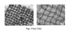
FIGS. 27( a)-27(b) show cell culture results after two days for the hydrogel scaffolds of FIGS. 26( a)-26(c).
DETAILED DESCRIPTION
Viscoelastic “inks” designed to have dynamic and mechanical properties suited for printing three-dimensional (3D) hydrogel architectures are described herein. Using direct ink writing, the viscoelastic inks may be applied to a substrate to create planar or 3D hydrogel scaffolds of predetermined dimensions, geometry, and microperiodicity. Direct ink writing is a layer-by-layer assembly technique that allows scaffolds to be formed with lateral feature sizes that are at least an order of magnitude smaller than those achieved by ink-jet printing and other rapid prototyping approaches and nearly comparable in size to those produced by two-photon polymerization and interference holography.
Central to the approach is the creation of concentrated inks that can be extruded through fine deposition nozzles in filamentary form and which undergo rapid solidification to maintain their shape even as they span gaps in the underlying layer(s). Unlike prior efforts on polyelectrolyte inks that required reservoir-induced coagulation to enable 3D printing, the inventive viscoelastic inks can be printed directly in air, where they undergo solidification via photopolymerization. The resulting hydrogel scaffolds may be tailored for use as tunable optical sensors, stimuli-responsive soft materials, and tissue engineering scaffolds. For tissue engineering applications, the hydrogel scaffolds may be dissolved in vivo or chemically cross-linked to provide permanent cellular support.
A direct ink writer that includes a 3-axis micropositioning stage and a syringe for housing the ink mounted on the micropositioning stage may be employed to form the hydrogel scaffolds. Referring to FIGS. 1( a) and 1(b), the ink is extruded through the tip of a tapered micro-capillary nozzle to form a hydrogel filament that is deposited onto a stationary substrate (e.g., a glass substrate). The extrusion occurs at a predetermined pressure and deposition speed. After patterning the initial layer, the nozzle is incrementally raised in the z-direction to generate the next layer. This process is repeated until the desired 3D structure is formed. 3D periodic scaffolds composed of a simple tetragonal geometry, for example, can be assembled by patterning an array of parallel filaments in the x-y plane such that their orientation is orthogonal to the layers immediately above and below a given layer. Photocuring with ultraviolet (UV) light may be carried out as the filament exits the nozzle or after deposition of the filament on the substrate.
The viscoelastic inks extruded through the micronozzle preferably include a long chain polymer and a photopolymerizable moiety, which may be a photopolymerizable monomer or a photopolymerizable group attached to the long chain polymer. The inks may also include a crosslinking agent, a photoinitiator, and water. The long chain polymer is present at a concentration in the ink sufficient to be physically entangled, that is, at a concentration well above the dilute-to-semidilute transition c* of the long chain polymeric species in the ink, where
c * = M w 4 / 3 π R g 3 N A ,
Mw=polymer molecular weight, Rg=radius of gyration of the polymer chains in solution, and NA=Avogadro's number. For example, the concentration of the long chain polymer may be at least about 5 times greater than the critical overlap concentration c*, or at least about 10 times greater than the critical overlap concentration c*. The concentration of the long chain polymer may also be at least about 100 times greater than the critical overlap concentration c*.
The long chain polymer may be, for example, polyacrylamide (pAM), poly(2-hydroxyethyl methacrylate) (pHEMA), poly(hyaluronic acid) (pHA), poly(N-isopropylacrylamide) (PNIPAAm), poly(ethylene oxide)/polyethylene glycol diacrylate, poly(vinyl alcohol), PLA/PGA/PLGA, block copolymers such as poloxamers (e.g., Pluronics®), polyphosphazene, alginate derivatives, or collagen derivatives. Generally, the concentration of the long chain polymer in the ink is about 5 wt. % or greater, about 10 wt. % or greater, or about 20 wt. % or greater. For example, the concentration may lie between about 5 wt. % and about 50 wt. % depending on the molecular weight of the long chain polymer.
The viscoelastic inks may include a photopolymerizable monomer, such as monomeric acrylamide or hydroxyethyl methacrylate in the case of inks based on pAM or pHEMA, respectively. During photocuring, the monomer forms a chemically crosslinked polymer network that penetrates the physically entangled polymer chains. The monomer may be present in the ink at a concentration in the range of from about 25 wt. % to about 55 wt. %. Other inks, such as those based on pHA, may include long chains of the polymer chemically modified with photopolymerizable groups (e.g., methacrylate groups) that allow the chains to participate in the crosslinking when photocured.
The long chain polymer generally comprises polymer chains having a molecular weight of at least about 300,000. The molecular weight may also be at least about 500,000. The long chain polymer may include a multimodal (e.g., bimodal) distribution of molecular weights. For example, the long chain polymer may include first polymer chains having a first molecular weight (e.g., in the range from about 300,000 to about 500,000) and second polymer chains having a second molecular weight (e.g., in the range of from about 1,000,000 to about 1,500,000). The concentration of the first polymer chains in the ink may be the same as or different from that of the second polymer chains. For example, as discussed further below in reference to an exemplary pHEMA ink system, the concentration of the first polymer chains in the ink, which have a molecular weight of 300,000, may be higher than the concentration of the second polymer chains, which have a molecular weight of 1,000,000. In this exemplary system, the concentrations are 25 wt. % and 10 wt. % for the first and second polymer chains, respectively.
By varying the pressure and deposition speed of the direct writing process, a given viscoelastic ink may be used with a variety of nozzle diameters. Typically, the ink is extruded through the micro-capillary nozzle under an applied pressure of between about 60 kPa and about 600 kPa at a deposition speed ranging from about 50 μm·s−1 to about 500 μm·s−1. For example, the applied pressure may be between about 100 kPa and about 500 kPa, or between about 200 kPa and about 400 kPa, and the deposition speed may range from about 100 μm·s−1 to about 400 μm·s−1, or from about 200 μm·s−1 to about 300 μm·s−1. The micro-capillary nozzle generally has a tip diameter ranging from about 1 micron to about 100 microns in size. For example, the nozzle (tip) diameter may be between about 1 micron and about 50 microns, or between about 5 microns and about 10 microns. Accordingly, the ink may be extruded through the micronozzle at a shear rate of at least about 10 s−1, or at least about 100 s−1. Due to the viscoelastic nature of the polymers, the ink exhibits a high viscosity at a low shear rate (e.g., about 0.1 s−1 or less) and a substantially reduced viscosity during the extrusion through the micronozzle. The viscosity may reduced by an order of magnitude or more during the extrusion, a phenomenon referred to as “shear-thinning” behavior. For example, the viscosity of the ink during extrusion may be about 20 Pa·s or less compared to about 1,000 Pa·s at a low shear rate.
The extruded filament(s) are patterned to form the hydrogel scaffold, which may have a single or multilayer structure made up of interconnected rods. The rods typically have a width (or diameter) in the range of from about 1 micron to about 10 microns and a spacing (or pitch) in the range of from about 5 microns to about 100 microns. For example, the pitch may be between about 1 micron and about 100 microns, between about 10 microns and about 80 microns, or between about 20 microns and about 60 microns. Generally, scaffolds formed by direct ink writing include from 1 to 20 or more layers. The scaffold may be periodic in one dimension, in two dimensions, or in three dimensions.
Due to the in-situ or post-deposition photocuring step, the extruded hydrogel filament has a pre-polymerized structure and a post-polymerized structure, each of which may have different elastic properties. The pre-polymerized structure of the hydrogel filament includes a physically entangled polymer network with no chemically crosslinked polymer chains. This physical gel structure exhibits elastic and viscous behavior that is well suited for extrusion through the micronozzle. In contrast, the post-polymerized structure of the hydrogel filament may include a physically entangled polymer network and a chemically crosslinked polymer network. For example, an ink including a long chain polymer as well as a photopolymerizable monomer may be transformed by photocuring to have an interpenetrating physical and chemical gel structure. Alternatively, the post-polymerized structure may include a chemically crosslinked polymer network with no physically entangled polymer chains. This structure may result from photocuring of an ink containing a physically entangled long chain polymer that has been chemically modified to include photopolymerizable groups along its backbone; as a result, the long chain polymer itself participates in the cross-linking and the physical gel structure is transformed to a chemical gel structure during photocuring. It is also possible for the post-polymerized structure of the hydrogel filament to include only a physically entangled polymer network with no chemical crosslinks. In this case, the elastic properties of the starting sol-gel ink and the extruded hydrogel filament may be similar, and relatively weak scaffolds may be prepared. Such scaffolds may be ideal for differentiation of primary stem cells into neuronal cells, for example.
For other scaffold applications, however, it may be advantageous for the post-polymerized structure of the hydrogel filament(s) to exhibit a shear elastic modulus G′2 that is at least two orders of magnitude greater than the shear elastic modulus G′1 of the pre-polymerized structure. The shear elastic modulus G′2 may also be at least three orders of magnitude greater than the shear elastic modulus G′1. Such an increase in the stiffness of the filaments prevents or minimizes deformation (e.g., sagging or collapse) of the resulting hydrogel scaffold. This enhanced stiffness may be obtained from polymerized hydrogel filaments that include either or both physically entangled and chemically cross-linked polymer chains, as supported by various elasticity data described below.
Typically, UV radiation having a wavelength in the range of from 250 nm to 400 nm is employed for photopolymerization, and the intensity of the radiation generally lies in the range of from about 50 mW/cm2 to about 400 mW/cm2. Alternatively, the ink may be polymerized by another means (e.g., chemicals, heat, etc.)
After polymerization, the hydrogel scaffold may be chemically treated (if needed) to render the scaffold compliant for tissue growth. For example, the hydrogel scaffold may be immersed in a polylysine solution. Then, cells such as 3T3 murine fibroblasts, primary rat hippocampal neurons and human embryonic stem cells may be plated onto one-, two- and four-layer hydrogel scaffolds, as described below, to demonstrate their biocompatibility and potential suitability for tissue engineering applications.
Polyacrylamide (pAM) Based Ink System
One approach to creating a viscoelastic pAM ink includes first mixing monomeric acrylamide, glycerol, and water. Upon ageing for several hours under ambient conditions, the monomeric species polymerize to yield a gel composed of 30 wt. % polyacrylamide. (Alternatively, high molecular weight polyacrylamide chains can be mixed directly with monomer to create the ink.) 1HNMR reveals that peaks associated with acrylamide, which are present initially, disappear after polymerization, followed by the emergence of two new peaks that correspond to alkyl chains (data not shown). Concomitantly, as the solution ages, sharp rises in both the shear elastic, G′, and loss, G″, moduli are observed, suggesting that the resulting gel is composed of physically entangled, polyacrylamide chains (see FIG. 2( a)). To determine their degree of polymerization, N, the intrinsic viscosity, [η]0, of diluted polymer solutions is measured by capillary viscometry and found to be [η]0≈270 ml gm−1 (see FIG. 2 b). Using the Mark-Houwink relation, [η]0=KMa, their molecular weight is determined to be 8.9×10⁵ gm mol−1, where K is 9.3×10⁻³ and a is taken to be 0.75 for polyacrylamide dissolved in an aqueous solution (0.5 M NaCl). Hence, this initial polymerization process yields polyacrylamide chains with an average degree of polymerization, N=1.3×10⁴, that is well above the entanglement value of Ne=128.
To further optimize the ink for direct-write assembly, this polymerized mixture is diluted by adding monomeric acrylamide, a crosslinking agent, N,N methylene bisacrylamide, a photoinitiator, diethoxyacetophenone, and deionized water at weight ratios (w/w) of 0.480, 0.036, 0.004, and 0.480, respectively. As noted above, the initial polymerization step could be eliminated simply by adding high molecular weight polyacrylamide chains (˜106 g/mol) directly to this photopolymerizable solution.
The final ink formulation exhibits pronounced shear thinning behavior, which facilitates its flow through fine deposition nozzles (see FIG. 2( c)). For example, when the ink is printed through a 5 μm nozzle at 0.5 mm s−1, which corresponds to an estimated shear rate of 100 s−1, its viscosity is approximately 10 Pa·s. Under these conditions, the ink viscosity is nearly three orders of magnitude smaller than that observed at low shear rates 0.1 s−1). Upon diluting the ink, its shear elastic modulus decreases by about an order of magnitude to ˜3×10³ Pa relative to its initial state (see FIG. 2( d)). Although this elasticity is sufficient for patterning 3D microperiodic scaffolds, the printed ink filament is advantageously further stiffened to prevent subsequent deformation, which occurs when the build times exceed several minutes. To obviate this, the direct writing process may be modified by mounting a fiber optic guide onto the printhead, which facilitates in-situ photopolymerization of the ink after it exits the gold-coated micronozzle (see FIG. 1( a)). Note, the metallic coating prevents the ink from prematurely cross-linking within the glass nozzle due to UV illumination, thereby avoiding clogging during the printing process.
Using this modified DIW process, hydrogel scaffolds with precisely defined filament diameter, spacing, number of layers, and geometry may be patterned. As a first example, hydrogel scaffolds composed of 5 μm filaments with a 20 μm spacing between filaments with 1-4 layers and a total area of 5 mm2 (see. FIG. 3( a) and FIG. 3( b)) are created. To further demonstrate the capability of this approach, hydrogel scaffolds are printed with nominally 1 μm filaments with 5 μm spacing between filaments and 6 layers with a total area of 1 mm2, as shown in FIG. 3( c). In this case, the hydrogel scaffolds are patterned in a face-centered tetragonal structure, in which the individual filaments are observed to span distances approximately five times their diameter with minimal deflection (see FIG. 3( c), inset).
To determine the suitability of the scaffolds for tissue engineering applications, 3T3 murine fibroblast cells are plated onto a flat glass substrate (control) as well as 1D and 3D microperiodic hydrogel scaffolds. Poly-d-lysine is absorbed into the hydrogel scaffold network prior to cell seeding to enhance their cytocompatibility. The fibroblasts plated on the control substrate display the typical flattened out morphology of cells typically seen in planar in vitro cultures, as shown in FIG. 4( a). By contrast, cell interactions with patterned features and the underlying glass substrate result in their alignment along the patterning direction of the 1D microperiodic hydrogel scaffolds, as shown in FIG. 4( b). This type of elongated morphology is similar to that observed by Zhang, et al. (S. Zhang et al., Biomaterials, 1999, 20, 1213) in which murine fibroblasts formed aligned cell arrays on 1D periodic patterned surfaces that were biofunctionalized by microcontact printing of a self-assembling oligopeptide monolayer. In the present investigation, atypical fibroblast morphology was observed in response to the 3D microperiodic hydrogel scaffolds (see FIGS. 4( c) and 4(d)), in which fibroblast cells integrate themselves into the regions between interconnecting hydrogel filaments. Typically one, or at most two, cell(s) reside in this space between filaments, essentially compartmentalizing themselves. It appears that the cells tend to sit in the square well created by interconnected filaments and then grow down into the scaffold towards the underlying glass substrate. Additionally, when the fibroblasts are in neighboring compartments, interactions between the filaments of adjacent fibroblast cells are observed (see FIG. 4( d)).
Material System:
The ink is initially formed by mixing 1 ml deionized water (Milli-Q, Millipore), 5 g of glycerol (Sigma Aldrich) and 3.5 g acrylamide (Acros). These constituents are magnetically stirred at 30° C. until the acrylamide fully dissolves. In the quiescent state, this solution undergoes spontaneous polymerization within hours to days. If the polymerization is slow, 0.1 M MgCl2 can be added as a catalyst. After this process is complete, 2 ml of deionized water (Milli-Q, Millipore) are added to this highly viscous solution. A separate solution is produced by mixing 5 ml deionized water (Milli-Q, Millipore), 5 g acrylamide (Acros), 0.3 g methylene bisacrylamide (MP Biomedicals), 0.04 ml diethoxyacetophenone (Acros), and 0.018 g Fluorescein O-acrylate (Sigma Aldrich). 2 ml of this second solution are added in 0.5 ml aliquots to polymerized solution until the desired rheological properties are attained. Note, the fluorescently-labeled monomor is incorporated to facilitate direct imaging of the patterned scaffolds after cell culture is complete.
NMR Analysis:
1HNMR measurements are carried out on a Varian Unity 400. The sample is prepared identically to the initial ink formulation; however D2O is substituted for deionized water to generate an improved signal with better alignment. Specifically, 1 ml D2O, 5 g of glycerol (Sigma Aldrich) and 3.5 g acrylamide (Acros) are mixed together in solution. These constituents are magnetically stirred at 30° C. until the acrylamide fully dissolves. Samples are analyzed prior to and post polymerization with NUTS (Acorn NMR) software package.
Ink Rheology:
Oscillatory rheometry is performed on the initial ink solution using a cup and bob geometry at a frequency of 1 Hz and shear stress of 1 Pa. Oscillatory rheometry is also performed on the final ink mixture at 1 Hz at a shear rate range from 0 to 200 s−1 to determine the elastic modulus (G′), loss modulus (G′), and yield stress (τy) of the printable ink. Viscometry is performed on the final ink mixture, from shear rates of 0 to 200 s−1. All data is taken using a cup and bob geometry (C15; Bohlin) with 3 cc of material on a Bohlin CVOR controlled-stress rheometer.
Capillary rheology is performed by first dissolving the initial ink solution after polymerization is completed in water and then precipitating the polyacrylamide by immersion in ethanol. The monomeric acrylamide and glycerol are soluble in ethanol, while poly(acrylamide) is not. This process is repeated several times while concomitantly ultrasonicating the solution to facilitate dissolution. The precipitated polymer is then dissolved at varying concentrations in an aqueous solution containing 0.50 M NaCl. The relative and specific viscosities of these diluted polymer solutions are then measured, as a function of flow time, in an Ubbelholde viscometer in a constant temperature bath held at 26.5±0.2° C. The intrinsic viscosity is determined by measuring the flow values at different concentrations and using both the Huggins (Eq. 1) and Kraemer (Eq. 2) relationships:
η - η s η s c = [ η ] + k H [ η ] 2 c ( 1 ) ln ( η / η s ) c = [ η ] + ( k H - 1 2 ) [ η ] 2 c ( 2 )
where ηs is the solvent viscosity, η is the apparent viscosity, c is the polymer concentration, and kH is the Huggins coefficient. By extrapolating these equations to c=0, the intrinsic viscosity is determined.
Direct-Write Asssembly of Hydrogel Scaffolds:
Micropipette tips (World Precision Instruments) with diameters ranging from 1 to 10 μm are coated with a thin gold film (200 nm thick) to prevent photopolymerization of the ink prior to exiting the deposition nozzle. The micropipettes are mounted onto a rotating holder to ensure an even coverage and coated inside a metal evaporator (Denton Vacuum DV-5024). Coverslip substrates are cleaned in piranha (sulfuric acid, hydrogen peroxide) solution for 1 h, rinsed with deionized water, and dried with nitrogen. Coverslips are placed in a 98% toluene (Fisher Scientific), 2% 3-(trimethoxysilyl)propyl methacrylate (Acros) solution for 18 hours at 60° C. The slides are removed just prior to drawing, rinsed with isopropanol, and dried. The ink is loaded into a syringe, with an attached gold-coated tip in place. Once the substrate is leveled, ink flow is initiated by applying a pressure of 70-80 psi. After the flow has begun, the pressure is reduced to 20-30 psi and the patterning is initiated. The printed scaffolds are defined by filament width, spacing between filaments, total patterned area, number of layers, and their geometry. We create both planar and 3D scaffolds with 1 to 5 μm filaments and a 5 to 20 μm spacing between filaments over 5 mm2 areas with 1-6 layers. A UV lamp (Omnicure S200; Exfo), with a λ=320 nm-400 nm, is used to expose the patterned structure to 5 mW/cm2 during the deposition process. Once patterning is complete, the scaffolds are exposed to a higher intensity UV light source, ˜400 mW/cm2, for 20 min to ensure a fully photo-cured structure. To drive off excess water and enhance scaffold rigidity, each scaffold is then heated to 100° C. for 18 hours.
Scaffold Imaging:
The printed hydrogel scaffolds are soaked in deionized water (Milli-Q, Millipore) for 3 days prior to cell culture to leach out glycerol and any unpolymerized acrylamide. Reflected light optical microscopy (IX71; Olympus) is performed prior to cell plating to ensure structural integrity of the scaffolds. SEM micrographs are obtained with a Philips XL30 ESEM-FEG; structures are dried and sputter-coated with gold prior to imaging.
3T3 Fibroblast Seeding and Imaging:
The interaction of murine NIH/3T3 fibroblast cells with the printed hydrogel scaffolds are investigated to assess their cytocompatibility. The initial cell stock (density of ˜1×10⁶ cells/ml) is divided between three T-75 cell culture flasks, to which 20 ml of cell media (Dulbecco's Modified Eagle Medium, DMEM) that consists of 4.5 g/L glucose, 4 mM glucose, 1 mM sodium pyruvate, 1.5 g/L sodium bicarbonate and supplemented with 10% fetal bovine serum (FBS, Colorado Serum Company) and 100 U/ml penicillin/100 μg/ml streptomycin (Sigma Aldrich) is added. The media is exchanged the next day to remove excess dimethyl sulfoxide (DMSO, Sigma Aldrich). Cells are grown in a humidified incubator at 37° C. with 5% CO2.
Hydrogel scaffolds are sterilized prior to cell plating, through UV light exposure in the laminar flow hood for 20 min. Scaffolds are immersed in 100 μg/ml poly-d-lysine (Sigma Aldrich) for 60 min prior to seeding. Flat glass coverslips are also evaluated as controls. Cells are plated onto the scaffolds at approximately 0.5×10⁶ cells/ml and allowed to proliferate for approximately 48 h. After 2 days in culture, the fibroblasts are rinsed 3 times with PBS, immersed in 4% paraformaldehyde at room temperature for 10 min and then rinsed again with PBS. A PBS solution containing 0.25% Triton X-100 is placed on the cells for 3 min to permeate their membranes and then the samples are rinsed again with PBS. The cells are then incubated in 1% bovine serum albumin (BSA, Sigma Aldrich) in PBS for 10 min. The cells are then incubated for an additional 20 min in a rhodamine-phalloidin (Invitrogen Molecular Probes) solution diluted 1:200 in 1% BSA solution, and again rinsed with PBS. Finally, the samples are incubated with 0.002% DAPI in PBS (4′,6-diamidino-2-phenylindole, Invitrogen Molecular Probes) for 1 min and rinsed with deionized water. The rhodamine-phalloidin stains actin filaments red, while the DAPI stains the DNA in the nucleus blue. All fluorescent microscopy is performed using the Zeiss Axiovert 200M inverted microscope. A Dapi/Hoechts/AMCA filter (Chroma Technology) is used for the DAPI imaging, a Special Yellow Rhodamine/Cy3/Texas Red filter (Chroma Technology) is used for the rhodamine imaging and the Piston GFP filter is used for imaging the autofluorescence in the hydrogel scaffold.
Poly(2-Hydroxyethyl Methacrylate) (pHEMA) Based Ink Systems
Poly(2-hydroxyethyl methacrylate) (pHEMA) scaffolds with varying 3D microperiodic architecture are created by direct-write assembly, and then rendered growth compliant for primary rat hippocampal neurons by absorption of polylysine. Neuronal cells thrive on these 3D scaffolds, forming differentiated, intricately branched networks. Confocal laser scanning microscopy reveals that both cell distribution and extent of neuronal process alignment depend upon scaffold architecture.
Mammalian tissues are composed of intricate matrices of individual cells that receive complex cues from their three-dimensional (3D) environment. Yet standard cell culture methods rely on two-dimensional (2D) substrates that are poor mimics of real tissue environments. This deficiency is especially relevant to brain tissue, where neurons exchange critical information across synapses and the 3D organization of neurons and their supporting cells is critical for function. It is well known that neuronal cells, among others, are strongly influenced by their surrounding microenvironment; for example, process orientation is guided by both topographical and chemical cues. Most prior studies of neuronal cell cultures have focused on planar or semi-planar environments, even though emerging evidence suggests that many cell types display important biological differences in 3D systems. Hence, new biocompatible scaffolds with precisely controlled features and interconnected porous networks are desired to understand how 3D environments affect the integration and behavior of neuronal cells and other cell types.
Three-dimensional scaffolds of varying microperiodicity are created using a pHEMA-based ink that contains high molecular weight pHEMA chains dissolved in a photocurable HEMA monomer solution. In this ink design, the pHEMA chains serve as a viscosifying agent to allow the printed features to retain their filamentary shape and span gaps in the underlying layer(s). After printing, the 3D hydrogel scaffolds are photocured to enhance their mechanical integrity ensuring survival upon immersion in aqueous culture solution.
pHEMA Ink Preparation:
Poly(2-hydroxyethyl methacrylate) (pHEMA), Mw=300,000 and 1,000,000), hydroxyethyl methacrylate (HEMA), ethylene glycol dimethacrylate (EGDMA), and 2,2-dimethoxy-2-phenylacetophenone (DMPA) are obtained from Sigma-Aldrich (St. Louis, Mo.). pHEMA inks are prepared by first combining the following constituents: deionized water, HEMA monomer, and the crosslinker, EGDMA. The photoinititor, DMPA, is then added to this solution and stirred until dissolved. Finally, pHEMA is added and the mixture is stirred for 24-72 h until the pHEMA completely dissolves and forms a homogenous solution. The pHEMA inks are stored in a dark location to prevent premature crosslinking. An optimal ink formulation is 25 wt % pHEMA (300,000 Mw), 10 wt % pHEMA (1,000,000 Mw), 40 wt % HEMA, 23.5 wt % H2O, 1 wt % EGDMA, and 0.5 wt % DMPA.
Scaffold Fabrication:
Glass substrates (12 mm diameter, 0.17 mm thickness, Warner Instruments) are piranha cleaned and soaked in a 5% 3-(Trimethoxysilyl)propyl methacrylate (Sigma) in toluene solution at 60° C. overnight and rinsed with isopropanol. 3D pHEMA scaffolds are fabricated using a 3-axis micropositioning stage (ABL9000, Aerotech Inc.) controlled by customized software (3D Inks). The ink is housed in a syringe (3 ml, EFD Inc.) mounted on the stage and extruded through a tapered micronozzle (10 μm, World Precision Instruments) onto the prepared substrates under an applied pressure of 100-200 kPa (800 Ultra dispensing system, EFD Inc.) at a speed of 200 μm s−1. After patterning the initial layer, the nozzle is incrementally raised in the z-direction to generate the next layer, and repeated until the desired 3D scaffold architecture is formed.
After printing, each scaffold is exposed to UV light (OmniCure S2000, Exfo) for ˜20 min and soaked in deionized water for at least 12 h to remove any unreacted species. The scaffolds are printed with 6 layers with overall dimensions ranging from 1×1 mm2 to 1.16×1.16 mm2. The center-to-center separation distance (or pitch) between pHEMA filaments ranges from 30-80 μm. SEM images of 3D unseeded pHEMA scaffolds are taken with a Hitachi S-4700 SEM after coating samples with gold/palladium for 45 s (Emitech K575 Sputter Coater).
Four scaffold architectures are produced, each of which contains orthogonal arrays of cylindrical hydrogel rods (ca. 10 μm in diameter) with a varying center-to-center spacing between adjacent rods of 30, 40, 60, and 80 μm (see FIGS. 5( a)-5(d)). Prior to cell culture, scaffolds were sterilized for 20 minutes in a laminar flow hood. To render the scaffolds growth compliant for primary rat hippocampal neurons, they are chemically modified by immersion in a polylysine solution, where rapid absorption of these polypeptide species occurs (see FIGS. 10( a)-10(c)).
Cell Culture Results:
After sterilization and subsequent treatment with unlabeled polylysine, the 3D hydrogel scaffolds are plated with post-natal day 1 primary rat hippocampal neurons. After seven days in vitro, the cultured neurons form extensive differentiated networks within the 3D scaffolds, as shown in the reconstructed CLSM images in FIGS. 6( a)-6(d) and in lower magnification images provided in FIGS. 11( a)-11(d). The cells are integrated throughout each scaffold, with neuron response being dependent upon the scaffold architecture. As the spacing between adjacent patterned rods increases, there is a decrease in the number of cell somata that are fully integrated throughout the 3D scaffold and an increase in the number of neuronal networks established on the underlying glass substrate. The cell survival in each scaffold is high and the cultures develop stably without evidence of cell division. At seven days in vitro, cells show elaborate processes that exhibit MAP2, a protein commonly present in dendrites. (see FIGS. 12( a)-12(b))
FIGS. 6( a)-6(d) show a top view of each 3D scaffold that highlights neuronal process organization, as well as a reconstructed side view, which illustrate cell distribution along the vertical direction. For scaffolds with a pitch of 30 μm, the majority of cell somata and their respective processes are confined to the top layers of the scaffold (FIG. 6( a)). The neuronal processes clearly follow along the scaffold rods, which is expected given that hippocampal neurons preferentially attach to and follow along planar surface topographies, such as those formed by patterned post arrays. As the scaffold pitch increases to 40 μm, the neurons create highly branched and aligned networks where the cell bodies are well distributed within the vertical dimension (FIG. 6( b)). On this scaffold, the neuronal processes are able to penetrate all layers, instead of being confined to those near the top. When the scaffold pitch is further increased to 60 μm, the open pore channels are large enough to facilitate the partitioning of cells to lower layers, where they attach to the underlying substrate (FIG. 6( c)). On these scaffolds, however, three-dimensionally supported neuronal networks do develop. As the pitch is increased further to 80 μm, the dominant somata response is the formation of intricate neuronal networks on the underlying substrate surface (FIG. 6( d)). Typically, these networks consisted of 1-2 neurons in each compartmentalized “pore” space with cellular processes that interact and densely follow the contours of the overlaying scaffold rods.
The cell soma distribution is quantitatively assessed as a function of lateral and vertical position (FIGS. 7( a)-7(b)) by 3D image analysis of confocal scans acquired in a representative volume of 250×250ט50 μm3 within each scaffold. While the cells are well distributed laterally (FIG. 7( a)), the pitch between filaments determines their vertical distribution in these scaffolds (FIG. 7( b)). At the smallest pitch of 30 μm, the distribution is somewhat skewed to the upper layers of the scaffold (FIG. 7( b)). In this architecture, the characteristic pore size is ˜20-22 μm, which may hinder the ˜10 μm somata from efficiently integrating deep within the scaffold. In scaffolds with a 40 μm pitch (˜30-32 μm pores), the cell soma are well integrated vertically, while they tended to segregate to the region near the substrate in scaffolds with a pitch of either 60 or 80 μm.
To probe specific cell morphologies and process outgrowth behavior, individual cells are isolated and reconstructed in 3D through image analysis. Confocal images and reconstructions of representative cells are shown in FIG. 8( a)-8(d). In the actual images, the scaffold and cell nuclei are stained red and the processes are green. In the reconstructions, the nuclei are colored blue, the actin in the cytoskeleton is green, and the cell nuclei are colored red. The neuronal soma in FIG. 8( a) displays a pyramidal morphology, which is commonly present in planar in vitro cultures of hippocampal neurons. This 3D reconstruction reveals that the neuronal process follows underneath the scaffold on one side, while navigating over the top of the scaffold rod on the other. In FIG. 8( b), a cell body is seen to attach horizontally to the scaffold while its processes wrap around the adjacent rod in a high symmetry that maximizes multi-rod surface contacts. The inset reveals the process wrapping more clearly in a cross-sectional view. This behavior is most commonly observed on the topmost layers of scaffolds with the three smallest pitch sizes, where the neuronal processes can more easily access and interact with the entire circumference of the printed hydrogel rods. Somata with a distorted cell shape are also observed as they fit themselves between scaffold layers (see FIG. 13), highlighting a strong preference for interaction with the scaffold surface.
While it appears that the majority of cell bodies prefer to interact with these 3D scaffolds, some somata are vertically suspended with only their neuronal processes providing the necessary anchorage to the scaffold (FIG. 8( c)). This suggests significant neuronal migration after plating onto the scaffold structures. An interesting morphology is revealed in this image where, instead of wrapping around an individual hydrogel rod, the process wraps around junctions formed at orthogonal intersections between printed rods in adjacent layers (a behavior most typically observed on scaffolds of the two smallest pitch sizes). Broader contact guidance along the two perpendicular scaffold orientations is observed on all scaffold architectures. An example of this is given in FIG. 8( d), where the neuronal processes of a soma in a 30 μm pitch scaffold are clearly guided by the patterned features.
To quantify the neuronal process alignment, separate fast Fourier transforms (FFT) are calculated for both the scaffolds and neuronal processes observed in the 3D reconstructed images. FFTs acquired from a 3D scaffold (40 μm pitch) and corresponding neuronal processes, shown in FIGS. 9( a)-9(b), reveal the strong periodicity of both the scaffold and the interacting neuronal processes. The inset in FIG. 9( a) denotes the scaffold orientation. These images are analyzed and plotted for the specific rod and process fluorescence intensities as a function of angle (FIGS. 9( c)-9(d)). The similarities between the two polar plots indicate that the neuronal processes have a similar degree of periodicity as the scaffolds, signifying that the processes closely follow along the topography of the scaffold. The anisotropy of this process alignment on the scaffolds can be approximated from the 3D reconstructions, as shown in FIG. 9( e). As expected, the correlation length of this induced anisotropy decreases as the pitch size increases. The intensity line scans taken across the primary angle in the neuronal process FFTs, shown in FIG. 9( f), indicates that the processes exhibit a higher degree of periodicity within 3D scaffolds of smaller pitch (i.e., 30-40 μm). Interestingly, scaffolds with 40 μm pitch present a better peak-to-noise ratio than those of 30 μm pitch. This may be due to the increased proclivity for processes to form bridges that span between rods in scaffolds of finer pitch, as illustrated in FIG. 6( a).
In summary, 3D microperiodic hydrogel scaffolds offer a robust, biocompatible culture system for primary hippocampal neurons. Using confocal microscopy coupled with image analysis, cell-scaffold interactions were observed and quantified in 3D allowing further insight to neuronal development in complex environments. This programmable 3D platform offers new opportunities for studying and controlling the distribution of hippocampal neurons in three dimensions, which may be extended to other sensitive cell types and tissues.
Ink Rheology:
To achieve greater control over the rheological properties, a bimodal molecular weight distribution of pHEMA may be used to form the ink. By blending two different molecular weights (300 k and 1M g/mol) of pHEMA, optimal rheological behavior can be obtained. The SEM images of FIGS. 14( a)-14(d) demonstrate the process flexibility of the hydrogel ink composed of 35 wt % pHEMA with a 5:2 ratio of 300 k and 1M g/mol polymers. The pHEMA ink can be printed through nozzles ranging from 1 to 10 μm into filaments without deformation. The vertical spacing can also be increased by printing adjacent layers aligned in the same direction, as demonstrated for the double layered scaffold in FIG. 14( b).
FIGS. 15( a)-15(b) illustrate the low shear viscosity and elastic modulus (G′) as a function of polymer concentration for 300 k and 1M g/mol pHEMA solutions and pHEMA-based inks comprised of a 5:2 300 k:1M polymer ratio blend. Although the curves look similar, the 1 g/mol pHEMA contributes significantly to increasing the viscosity of the solution. For example, there are three compositions that have a similar GL100 Pa: 25 wt % 1M g/mol, 35 wt % 5:2 300 k:1M weight ratio blend, and 40 wt % 300 k g/mol pHEMA. However, the viscosities for these solutions are 480 Pa·s, 110 Pa·s, and 60 Pa·s, respectively.
The high molecular weight chains impart important properties to the ink. The longer chains align under shear, decreasing the viscosity as the shear rate increases. The ratio of the high shear viscosity (100 1/s) to the low shear viscosity is presented as a function of polymer concentration. FIG. 16( b) shows an example of the shear thinning behavior for the 35 wt. % 5:2 300 k:1M weight ratio blend pHEMA ink. The polymer blends shear thin significantly, even at low concentrations, caused primarily by the higher molecular weight component. This behavior improves printability, as the ink must be able to easily flow out of the micronozzle under an applied shear. Additionally, the long chain polymers aid in forming a continuous filament during the printing process.
Instead of a photoinitiator, a thermal initiator can be used to probe the rheological properties during the curing of the ink as a function of temperature. In FIG. 17( a), the amount of monomer concentration of the ink is varied while maintaining the polymer concentration at 35 wt. % and the crosslinker concentration at 1 wt. %. Changing the monomer concentration has little effect on the rheological properties of the ink, but the corresponding cured hydrogels have elasticity values that are increased by over two orders of magnitude, from 3 to 190 kPa (FIG. 17( b)). Some drying does occur in the rheometer from EtOH, which is used to help dissolve the polymers when the monomer concentration<30%.
Referring to FIGS. 18( a)-18(b), the amount of crosslinker can also affect the cured hydrogel's elastic properties. Varying the amount of the crosslinker, EGDMA, from 0 to 7.5 wt % gives a range of G′ from 130 to 670 kPa. E′ has also been measured using AFM nanoindentation on printed scaffolds and similar values were found.
Additional Experimental Details
Hippocampal Neuron Culture:
Prior to use in culture, pHEMA scaffold samples were sterilized for 20 min with UV, treated with poly-D-lysine (MW: 30-70 kDa, Sigma) at 100 μg/ml for 1 h, and then allowed to sit for 1 h.
Hippocampal neurons are isolated from post-natal day one (P1) Long Evans/BluGill rats (University of Illinois-Urbana Champaign). The brains are removed, the hemispheres separated, and the hippocampi dissected. Dissected tissue is kept in a 35 mm petri dish, surrounded by ice and filled with cold Hibernate A base solution (Brain-Bits), supplemented with 2% B-27 (Invitrogen) and L-glutamine (0.5 mM, Sigma). Upon completion of dissection, the tissue is incubated with Papain enzyme (2 mg/ml, Worthington) at 37° C. for 15 min and then rinsed with 2 ml Hibernate A solution. The solution is removed, an additional 2 ml of Hibernate is added, and then the tissue is triturated approximately 10 times. After allowing the large pieces of tissue to settle, the cell solution is collected. This step is repeated at least once. The cell solution is centrifuged for 5 min at 3G and then reconstituted with 0.5 ml of Neurobasal base solution (Gibco), supplemented with 2% B-27 (Invitrogen), L-glutamine (0.5 mM), and 1% pen-strep (Sigma). The remaining large chunks of tissue are incubated again with papain enzyme (2 mg/ml) for 15 min and the above process is repeated. Once the incubation time is complete, the cell suspensions are combined and used to plate the scaffold substrates at an initial density of approximately 500 cells/mm2. The neurons are maintained in a humidified environment at 37° C. with 5% CO2 and supplemented with Neurobasal media twice weekly for one week.
Confocal Imaging:
Confocal images are acquired using a Zeiss LSM 710 multi-photon confocal microscope. Tiled images of the entire scaffold are obtained using the 25× objective, which are composed of either 3×3 tiles (927 μm×927 μm) or 4×4 tiles (1270 μm×1270 μm) depending on the scaffold architecture. In addition, 2×2 tiled images (250 μm×250 μm) are captured using a 40× objective for data analysis.
Image Analysis:
Confocal z-stacks were reconstructed using Imaris software (Bitplane, Inc.). The distribution of cells was determined using the Spots Analysis. At least two samples, from different culture dates, are analyzed for each scaffold architecture. Position data is imported into MATLAB (The MathWorks) and viewed in 3D from the x-z plane, in which cell size is varied to indicate its position along the y-axis.
Scaffold and neuronal process z-stacks are reconstructed into separate 3D arrays using MATLAB. A Multidimensional Fast Fourier Transform (FFT) package is used to analyze the 3D arrays. The function ‘fftn’ is used to determine the 3D FFT; ‘fftshift’ is then used to center the low frequency components of the transform. The power spectrum is taken as the log of the absolute value of the centered transform and scaled identically between samples to display in the grayscale color range 0 to 255. In order to determine the orientation of the neuronal processes, the ‘fanbeam’ function is used to integrate around the lateral (x-y) and vertical (x-z) orientations, in which the lateral orientation possesses the highest intensity. Only the center beam of the ‘fanbeam’ projection is used in a 360° rotation. A low pass filter is used on each FFT image to remove the lowest value, and then the data is normalized. Intensity linescans are taken across the primary angle in the process FFT images using ImageJ (U.S. NIH). Dilated scaffold 3D arrays are subtracted from the process 3D arrays to calculate the percent of the neuronal network on the scaffold.
Immunocytochemistry—Actin/Nucleus Staining:
After 7 days in culture, neurons are rinsed 3 times with PBS, immersed in 4% paraformaldehyde at room temperature for 30 min and then rinsed again with PBS, 2×. A PBS solution containing 0.1% Triton X-100 is placed on the samples for 15 min to permeablize cellular membranes, before rinsing again with PBS (0.1% Tween). The samples are then incubated in ITsignal FX (Invitrogen Molecular Probes) for 30 min and then rinsed briefly with PBS (0.1% Tween). Samples are incubated in a 1:100 solution (with PBS and 100 μl of ITsignal FX) of mouse anti-actin monoclonal antibody (MP Biomedicals, Solon, Ohio) for 2 h and then rinsed with PBS (0.1% Tween), 3× (5 min). Cells are incubated for 1 h with a secondary antibody, Goat Anti-Mouse Alexa 568 (Invitrogen Molecular Probes) in a 1:200 dilution (with PBS and 100 μl of ITsignal FX) in the dark. Samples are rinsed with PBS (0.1% Tween), 3× (5 min) and then exposed to To-Pro3 (Invitrogen Molecular Probes) at 5 μM in PBS, for 30 min in the dark. Once the exposure is complete, the samples are rinsed briefly with PBS (Tween 0.1%) and then mounted in Prolong Gold (Invitrogen). Samples are sealed after 24 h and kept covered, at 4° C. until imaged. Note, samples from 4 different in-vitro experiments are stained using this protocol and analyzed.
Immunocytochemistry—MAP2:
Samples are also stained for the cytoskeletal protein MAP2 in the following manner. After 7 days in vitro, samples are quickly rinsed 3× with warm PBS and then immersed in 4% paraformaldehyde (37° C.) for 30 min. Samples are rinsed 2× with PBS (0.1% Tween) and then exposed to 0.1% Triton X-100 PBS solution for 15 min. After another 2× rinse with PBS (0.1% Tween), the samples are incubated in a 5% goat serum PBS for 30 min. The samples are then exposed to primary MAP2 rabbit polyclonal antibody (Pierce) at a 1:100 dilution overnight at 4° C. and then rinsed 3× (5 min) with PBS (0.1% Tween). All of the following steps are completed in the dark. Samples are then exposed to a secondary goat-anti rabbit Alexa 568 antibody (Invitrogen Molecular Probes) for 1 h before again being rinsed 3× (5 min) in PBS (0.1% Tween). Finally, samples are exposed to TO-PRO3 (Invitrogen Molecular Probes) at 50 μM in PBS for 30 min. Samples are dried, mounted in Prolong Gold (Invitrogen Molecular Probes) and sealed after 24 h.
Protein Partitioning:
3D pHEMA scaffolds with a 40 μm pitch are exposed to 2 mg/ml solutions of FITC-Polylysine (MW: 30-70 kDa), FITC-Protein A, and FITC-IgG for 1 h. All proteins are purchased from Sigma. Samples are rinsed with deionized water and imaged using an Olympus Epifluorescent Microscope, AX-70 with a CCD camera (Optronic MagnaFire).
Poly(Hyaluronic Acid) (pHA) Based Ink Systems
Direct ink writing of poly(hyaluronic acid) (pHA) based ink systems also has been explored for the fabrication of tissue engineering scaffolds. Among the tested compositions are pure pHA and blended pHA-PEGDA systems, as indicated in Table 1 below. Excess water is initially added to aid in polymer dissolution; this excess water may be evaporated off under heating and stirring at a temperature of about 60° C.
TABLE 1
pHA-Based Ink Systems.
Component Pure pHA Blended 1 Blended 2
Poly(hyaluronic acid) 300 × 103 MW 300 × 103 MW  1.5 × 10⁶ MW - 3.5 wt. %
(pHA) or methacrylated  10 wt. %   10 wt. %  300 × 103 MW - 10 wt. %
hyaluronic acid blend
Polyethylene glycol  700 MW 700 MW - 10 wt.%
diacrylate (PEGDA)   8 wt. %
Photoinitiator Irgacure 2959 Irgacure Irgacure 2959 - 0.1 wt. %
0.1 wt. % or 2959
Darocur 1173  0.1 wt. %
  1 wt. %
Surfactant Tween 85 - 0.1 wt. %
Solvent 50% Glycerol 50% Glycerol Glycerol - 39.2 wt. %
50% Phosphate 50% PBS PBS - 39.2 wt. %
Buffered Saline
(PBS)
FIG. 19 shows printing of the 10 wt. % 300,000 Mw pHA system in 50% glycerol, 50% PBS with a 30 micron tip at a write speed of 750 microns/second, and FIG. 20 shows the oscillatory rheology for the pHA system, specifically G′ and G″ (elastic modulus and viscous modulus, respectively) as a function of shear stress. A smooth and well-printed 5-layer thick structure obtained at a write speed of 250 microns/sec and at a pressure of 30 psi using 10 wt. % pHA, 8 wt. % PEGDA in a 50% glycerol-50% PBS solution is shown in FIG. 21, and FIGS. 22 and 23 provide rheological data for the system.
Although the pure pHA system printed well, as indicated by robocasting tests, photocuring the printed scaffolds presented some challenges. It was determined that solubility issues were inhibiting proper photocuring. Irgacure was found to be better suited for the system. In order to improve the mechanical strength of the photocured scaffold, acrylated PHA was employed in addition to a greater concentration of PEGDA. However, there is a tradeoff; at concentrations higher than 10 wt. % PEGDA, the solution becomes oversaturated which may lead to inconsistent printing behavior.
In general, the pure pHA and Blended 1 ink systems are capable of multilayer 2D printing and print well from 100 μm tip dimensions to sub-10 micron tip dimensions. The systems may be cured using 1 minute of UV exposure at an intensity of approximately 100 mW/cm2 for 320 nm light and at an even lower intensity with 250 nm light. The structures can be cured while printing or after printing. Additionally, cured scaffolds have survived in cell media for greater than 2 weeks.
Process parameters for direct ink writing of the Blended 2 system (see Table 1) include the following: pressure of 10 psi, write speed of 100 mm/sec, tip size of 30 μm WPI (painted with nail polish), road width of 130 mm, Z spacing of 15 mm, dimensions of 1500 mm×1500 mm and 2000 mm×2000 mm, cure conditions of 5 W with the Exfo UV lamp for 20 minutes immediately following the completion of the structure, followed by post-curing/drying in the oven overnight (10-12 hours) at 65° C.
FIGS. 24( a)-24(b) show the rheology of the Blended 2 ink system, and FIG. 25 is an optical micrograph showing the as-printed structure prior to UV exposure. FIGS. 26( a)-26(c) are SEM images depicting the fabricated hydrogel scaffolds following UV exposure and drying. Cell culture studies carried out with human embryonic stem cells (hESC) indicate that the cells incorporate into scaffold compartments. FIGS. 27( a)-27(b) show the cell culture results after two days.
A generic design for formulating and depositing viscoelastic inks that have dynamic and mechanical properties ideally suited for printing 3D structures has been described. Three model inks systems have been shown to have excellent 3D-writing capabilities and also cytocompatibility with several types of human cells. The ability to create hydrogel scaffolds with microscale features in both planar and 3D forms may open a new avenue for tailoring scaffolds for tissue engineering as well as other applications, including coatings, absorbent materials, surface modifications, extrusion molding, biomaterials, flexible electronics, photonics, rapid prototyping, and photopolymerizable materials.
Although the present invention has been described in considerable detail with reference to certain embodiments thereof, other embodiments are possible without departing from the present invention. The spirit and scope of the appended claims should not be limited, therefore, to the description of the preferred embodiments contained herein. All embodiments that come within the meaning of the claims, either literally or by equivalence, are intended to be embraced therein. Furthermore, the advantages described above are not necessarily the only advantages of the invention, and it is not necessarily expected that all of the described advantages will be achieved with every embodiment of the invention.

Claims (19)

The invention claimed is:
1. A viscoelastic ink for direct writing of hydrogel structures, the ink comprising:
a polymer;
a photopolymerizable moiety;
a photoinitiator; and
water,
wherein the polymer comprises poly(hyaluronic acid) (pHA), methacrylated hyaluronic acid or a blend of the two and is present at a concentration of about 5 wt. % or greater in the ink.
2. The ink of claim 1, wherein the photopolymerizable moiety is selected from the group consisting of: a photopolymerizable monomer; and a photopolymerizable group attached to the polymer.
3. A method for forming a hydrogel scaffold, the method comprising:
forming an ink comprising a polymer and a photopolymerizable moiety, the polymer comprising poly(hyaluronic acid) (pHA), methacrylated hyaluronic acid or a blend of the two and being present at a concentration of about 5 wt. % or greater in the ink;
extruding the ink through a micronozzle to form an extruded filament;
photopolymerizing the extruded filament; and
depositing the extruded filament in a pattern on a substrate to form a hydrogel scaffold,
wherein the ink comprises a first viscosity at a low shear rate of about 0.1 s−1 and a second viscosity during the extrusion, the second viscosity being at least about an order of magnitude lower than the first viscosity.
4. The method of claim 3, wherein the second viscosity is about 20 Pa·s or less.
5. The method of claim 3, wherein the photopolymerization of the extruded filament occurs prior to depositing the extruded filament on the substrate.
6. The method of claim 3, wherein the photopolymerization of the extruded filament occurs after depositing the extruded filament on the substrate.
7. The method of claim 3, further comprising, after the photopolymerization, chemically treating the hydrogel scaffold to render the scaffold compliant for tissue growth.
8. The method of claim 7, wherein chemically treating the scaffold comprises immersing the scaffold in a polylysine solution.
9. The method of claim 3, wherein the concentration of the polymer is between about 10 wt. % and about 50 wt. %.
10. The method of claim 3, wherein the photopolymerizable moiety comprises a photopolymerizable monomer present at a concentration of between about 25 wt. % and 55 wt. %.
11. The method of claim 3, wherein the photopolymerizable moiety comprises a photopolymerizable group attached to the polymer.
12. The method of claim 3, wherein, after photopolymerization, the extruded filament comprises a physically entangled polymer network and a chemically crosslinked polymer network.
13. The method of claim 3, wherein, after photopolymerization, the extruded filament comprises a chemically crosslinked polymer network with no physically entangled polymer chains.
14. The ink of claim 1, wherein the ink further comprises polyethylene glycol diacrylate (PEGDA).
15. The ink of claim 14, wherein the PEGDA is present at a concentration in the ink of up to about 10 wt. %.
16. The ink of claim 15, wherein the concentration of the pHA, the methacrylated hyaluronic acid, or said blend of the two is 10 wt. % and the concentration of the PEGDA is 8 wt. %.
17. The method of claim 3, wherein the ink further comprises polyethylene glycol diacrylate (PEGDA).
18. The method of claim 16, wherein the PEGDA is present at a concentration in the ink of up to about 10 wt. %.
19. The method of claim 18, wherein the concentration of the pHA, the methacrylated hyaluronic acid, or said blend of the two is 10 wt. % and the concentration of the PEGDA is 8 wt. %.
US13/636,542 2010-03-24 2011-03-22 Viscoelastic ink for direct writing of hydrogel structures Active 2031-09-10 US9045657B2 (en)

Priority Applications (1)

Application Number Priority Date Filing Date Title
US13/636,542 US9045657B2 (en) 2010-03-24 2011-03-22 Viscoelastic ink for direct writing of hydrogel structures

Applications Claiming Priority (3)

Application Number Priority Date Filing Date Title
US31707610P 2010-03-24 2010-03-24
PCT/US2011/029429 WO2011119607A2 (en) 2010-03-24 2011-03-22 Viscoelastic ink for direct writing of hydrogel structures
US13/636,542 US9045657B2 (en) 2010-03-24 2011-03-22 Viscoelastic ink for direct writing of hydrogel structures

Publications (2)

Publication Number Publication Date
US20130084449A1 US20130084449A1 (en) 2013-04-04
US9045657B2 true US9045657B2 (en) 2015-06-02

Family

ID=44673836

Family Applications (1)

Application Number Title Priority Date Filing Date
US13/636,542 Active 2031-09-10 US9045657B2 (en) 2010-03-24 2011-03-22 Viscoelastic ink for direct writing of hydrogel structures

Country Status (2)

Country Link
US (1) US9045657B2 (en)
WO (1) WO2011119607A2 (en)

Cited By (5)

* Cited by examiner, † Cited by third party
Publication number Priority date Publication date Assignee Title
WO2019210428A1 (en) * 2018-05-03 2019-11-07 The University Of British Columbia Cell encapsulation compositions and methods for immunocytochemistry
US10889057B2 (en) 2016-05-12 2021-01-12 Hewlett-Packard Development Company, L.P. Material sets
US20220020972A1 (en) * 2020-07-20 2022-01-20 Universal Display Corporation Height Measurement and Control in Confined Spaces for Vapor Deposition System
US11305480B2 (en) * 2016-01-28 2022-04-19 3D Systems, Inc. Methods and apparatus for 3D printed hydrogel materials
US11364658B2 (en) * 2018-04-03 2022-06-21 Massachusetts Institute Of Technology Programmable soft materials containing ferromagnetic domains and methods of making

Families Citing this family (27)

* Cited by examiner, † Cited by third party
Publication number Priority date Publication date Assignee Title
AU2006270221B2 (en) 2005-07-15 2012-01-19 Micell Technologies, Inc. Polymer coatings containing drug powder of controlled morphology
BR112013009744A2 (en) 2010-10-21 2016-07-19 Organovo Inc fabric fabrication device, systems and methods
WO2013006399A2 (en) 2011-07-01 2013-01-10 The Board Of Trustees Of The University Of Illinois Multinozzle deposition system for direct write applications
WO2014165264A1 (en) * 2013-03-12 2014-10-09 Micell Technologies, Inc. Bioabsorbable biomedical implants
JP5819341B2 (en) * 2013-03-29 2015-11-24 富士フイルム株式会社 Curable composition, curable composition set, and image forming method
US9962905B2 (en) 2013-05-29 2018-05-08 Lawrence Livermore National Security, Llc Three-dimensionally patterned energy absorptive material and method of fabrication
BR112015032543A2 (en) 2013-06-24 2017-08-22 President and Fellows of Harvad College PRINTED THREE DIMENSIONAL (3D) FUNCTIONAL PART, PRINTING METHOD OF A THREE DIMENSIONAL (3D) FUNCTIONAL PART AND 3D PRINTER
JP6712220B2 (en) 2013-11-05 2020-06-17 プレジデント アンド フェローズ オブ ハーバード カレッジ Method for printing a tissue construct having an embedded vasculature
EP3071939B1 (en) 2013-11-18 2019-07-31 President and Fellows of Harvard College Printed stretchable strain sensor
WO2015100155A1 (en) * 2013-12-23 2015-07-02 Cornell University Printable elastomer materials
US20170072628A1 (en) * 2014-05-28 2017-03-16 Drexel University Nozzle for selectively generating either plasma or ultraviolet radiation
CN108398381A (en) * 2015-04-21 2018-08-14 上海交通大学医学院附属第九人民医院 The method of non-invasive dynamic monitoring material degradation rate and regeneration matching degree
WO2016176444A1 (en) 2015-04-29 2016-11-03 Northwestern University 3d printing of biomedical implants
AU2016257427A1 (en) 2015-05-05 2017-11-09 President And Fellows Of Harvard College Tubular tissue construct and a method of printing
KR20180008681A (en) 2015-05-18 2018-01-24 프레지던트 앤드 펠로우즈 오브 하바드 칼리지 Foam ink composition and 3D printed hierarchical porous structure
WO2016194011A1 (en) 2015-06-05 2016-12-08 Politecnico Di Torino Method for preparing cellularized constructs based on heat-sensitive hydro-gels
WO2017095773A1 (en) * 2015-11-30 2017-06-08 President And Fellows Of Harvard College Hydrogel composite ink formulation and method of 4d printing a hydrogel composite structure
US11124644B2 (en) * 2016-09-01 2021-09-21 University Of Florida Research Foundation, Inc. Organic microgel system for 3D printing of silicone structures
EP3306394B1 (en) * 2016-10-07 2019-12-04 Max-Planck-Gesellschaft zur Förderung der Wissenschaften e.V. Method for producing a structure with spatial encoded functionality
WO2018106705A1 (en) 2016-12-08 2018-06-14 President And Fellows Of Harvard College 3d printed core-shell filament and method of 3d printing a core-shell filament
WO2019183461A1 (en) * 2018-03-23 2019-09-26 Lawrence Livermore National Security, Llc Base-catalyzed sol-gel inks for direct ink writing of high resolution hierarchically porous carbon aerogels
US20200298466A1 (en) * 2019-03-22 2020-09-24 Lawrence Livermore National Security, Llc Additive manufacture of hierarchically porous materials with high resolution
US20210071018A1 (en) * 2019-09-11 2021-03-11 Board Of Regents, The University Of Texas System Compositions and methods for extrusion-based 3d printing of soft materials
CN112795235B (en) * 2020-12-31 2022-10-04 合肥工业大学 Preparation of nano composite hydrogel ink and application of nano composite hydrogel ink in 3D printing
CN113101420A (en) * 2021-03-29 2021-07-13 华南理工大学 Photo-crosslinking alginate-polyamide composite hydrogel stent and preparation method thereof
CN113248658B (en) * 2021-06-17 2022-04-19 韶关盛怡文具有限公司 High-viscoelasticity resin special for space pen ink, preparation method and ink using resin
CN115124756B (en) * 2022-07-14 2023-06-06 中国人民解放军国防科技大学 Preparation method of ultraviolet-assisted 3D printing polymer cross-linked silica aerogel

Citations (21)

* Cited by examiner, † Cited by third party
Publication number Priority date Publication date Assignee Title
US4321711A (en) 1978-10-18 1982-03-30 Sumitomo Electric Industries, Ltd. Vascular prosthesis
US4438253A (en) 1982-11-12 1984-03-20 American Cyanamid Company Poly(glycolic acid)/poly(alkylene glycol) block copolymers and method of manufacturing the same
US4704131A (en) 1982-04-19 1987-11-03 Koken Co., Ltd. Medical materials
US4826945A (en) 1987-06-09 1989-05-02 Yissum Research Development Company Biodegradable polymeric materials based on polyether glycols, processes for the preparation thereof and surgical articles made therefrom
US4842575A (en) 1984-01-30 1989-06-27 Meadox Medicals, Inc. Method for forming impregnated synthetic vascular grafts
US5034265A (en) 1983-08-01 1991-07-23 Washington Research Foundation Plasma gas discharge treatment for improving the compatibility of biomaterials
US5202413A (en) 1993-02-16 1993-04-13 E. I. Du Pont De Nemours And Company Alternating (ABA)N polylactide block copolymers
US5306311A (en) 1987-07-20 1994-04-26 Regen Corporation Prosthetic articular cartilage
US5410016A (en) 1990-10-15 1995-04-25 Board Of Regents, The University Of Texas System Photopolymerizable biodegradable hydrogels as tissue contacting materials and controlled-release carriers
US5415619A (en) 1989-12-13 1995-05-16 Korea Research Institute Of Chemical Tech. Method of manufacturing a vascular graft impregnated with polysaccharide derivatives
US5529914A (en) 1990-10-15 1996-06-25 The Board Of Regents The Univeristy Of Texas System Gels for encapsulation of biological materials
US5567440A (en) 1990-10-15 1996-10-22 Board Of Regents, The University Of Texas System Methods for modifying cell contact with a surface
US5573934A (en) 1992-04-20 1996-11-12 Board Of Regents, The University Of Texas System Gels for encapsulation of biological materials
US5584875A (en) 1991-12-20 1996-12-17 C. R. Bard, Inc. Method for making vascular grafts
US5843160A (en) 1996-04-01 1998-12-01 Rhodes; Valentine J. Prostheses for aneurysmal and/or occlusive disease at a bifurcation in a vessel, duct, or lumen
US5854382A (en) 1997-08-18 1998-12-29 Meadox Medicals, Inc. Bioresorbable compositions for implantable prostheses
US6514515B1 (en) 1999-03-04 2003-02-04 Tepha, Inc. Bioabsorbable, biocompatible polymers for tissue engineering
US20050008675A1 (en) 2001-07-03 2005-01-13 Bhatia Sangeeta N. Microfabricated biopolymer scaffolds and method of making same
US7141617B2 (en) * 2003-06-17 2006-11-28 The Board Of Trustees Of The University Of Illinois Directed assembly of three-dimensional structures with micron-scale features
WO2008069915A2 (en) 2006-11-20 2008-06-12 Poly-Med, Inc. Selectively absorbable/biodegradable, fibrous composite constructs and applications thereof
US20100158880A1 (en) * 2008-12-19 2010-06-24 Ethicon, Incorporated Regeneration and repair of neural tissue following injury

Family Cites Families (3)

* Cited by examiner, † Cited by third party
Publication number Priority date Publication date Assignee Title
US7291292B2 (en) * 2005-08-26 2007-11-06 E.I. Du Pont De Nemours And Company Preparation of silver particles using thermomorphic polymers
US20070059459A1 (en) * 2005-09-12 2007-03-15 Haixin Yang Ink jet printable hydrogel for sensor electrode applications
US7632546B2 (en) * 2005-11-30 2009-12-15 Xerox Corporation Radiation curable phase change inks containing gellants

Patent Citations (21)

* Cited by examiner, † Cited by third party
Publication number Priority date Publication date Assignee Title
US4321711A (en) 1978-10-18 1982-03-30 Sumitomo Electric Industries, Ltd. Vascular prosthesis
US4704131A (en) 1982-04-19 1987-11-03 Koken Co., Ltd. Medical materials
US4438253A (en) 1982-11-12 1984-03-20 American Cyanamid Company Poly(glycolic acid)/poly(alkylene glycol) block copolymers and method of manufacturing the same
US5034265A (en) 1983-08-01 1991-07-23 Washington Research Foundation Plasma gas discharge treatment for improving the compatibility of biomaterials
US4842575A (en) 1984-01-30 1989-06-27 Meadox Medicals, Inc. Method for forming impregnated synthetic vascular grafts
US4826945A (en) 1987-06-09 1989-05-02 Yissum Research Development Company Biodegradable polymeric materials based on polyether glycols, processes for the preparation thereof and surgical articles made therefrom
US5306311A (en) 1987-07-20 1994-04-26 Regen Corporation Prosthetic articular cartilage
US5415619A (en) 1989-12-13 1995-05-16 Korea Research Institute Of Chemical Tech. Method of manufacturing a vascular graft impregnated with polysaccharide derivatives
US5529914A (en) 1990-10-15 1996-06-25 The Board Of Regents The Univeristy Of Texas System Gels for encapsulation of biological materials
US5410016A (en) 1990-10-15 1995-04-25 Board Of Regents, The University Of Texas System Photopolymerizable biodegradable hydrogels as tissue contacting materials and controlled-release carriers
US5567440A (en) 1990-10-15 1996-10-22 Board Of Regents, The University Of Texas System Methods for modifying cell contact with a surface
US5584875A (en) 1991-12-20 1996-12-17 C. R. Bard, Inc. Method for making vascular grafts
US5573934A (en) 1992-04-20 1996-11-12 Board Of Regents, The University Of Texas System Gels for encapsulation of biological materials
US5202413A (en) 1993-02-16 1993-04-13 E. I. Du Pont De Nemours And Company Alternating (ABA)N polylactide block copolymers
US5843160A (en) 1996-04-01 1998-12-01 Rhodes; Valentine J. Prostheses for aneurysmal and/or occlusive disease at a bifurcation in a vessel, duct, or lumen
US5854382A (en) 1997-08-18 1998-12-29 Meadox Medicals, Inc. Bioresorbable compositions for implantable prostheses
US6514515B1 (en) 1999-03-04 2003-02-04 Tepha, Inc. Bioabsorbable, biocompatible polymers for tissue engineering
US20050008675A1 (en) 2001-07-03 2005-01-13 Bhatia Sangeeta N. Microfabricated biopolymer scaffolds and method of making same
US7141617B2 (en) * 2003-06-17 2006-11-28 The Board Of Trustees Of The University Of Illinois Directed assembly of three-dimensional structures with micron-scale features
WO2008069915A2 (en) 2006-11-20 2008-06-12 Poly-Med, Inc. Selectively absorbable/biodegradable, fibrous composite constructs and applications thereof
US20100158880A1 (en) * 2008-12-19 2010-06-24 Ethicon, Incorporated Regeneration and repair of neural tissue following injury

Non-Patent Citations (29)

* Cited by examiner, † Cited by third party
Title
Brewer, Gregory J., "Isolation and Culture of Adult Rat Hippocampal Neurons," Journal of Neuroscience Methods 71 (1997) pp. 143-155.
Clark, Peter et al., "Growth Cone Guidance and Neuron Morphology on Micropatterned Laminin Surfaces," Journal of Cell Science 105 (1993) pp. 203-212.
Cukierman, Edna et al., "Taking Cell-Matrix Adhesions to the Third Dimension," Science 294 (2001) pp. 1708-1712.
Duoss, et al., "Sol-Gel Inks for Direct-Write Assembly of Functional Oxides," Advanced Materials 19 (2007) pp. 3485-3489.
Friedl, Peter et al., "Cell Migration Strategies in 3-D Extracellular Matrix: Differences in Morphology, Cell Matrix Interactions, and Integrin Function," Microscopy Research and Technique 43 (1998) pp. 369-378.
Ghosh, Sourabh et al., "Direct-Write Assembly of Microperiodic Silk Fibroin Scaffolds for Tissue Engineering Applications," Advanced Functional Materials 18 (2008) pp. 1883-1889.
Gratson, Gregory M. et al., "Direct Writing of Three-Dimensional Webs," Nature 428 (2004) p. 386.
Gratson, Gregory M. et al., "Phase Behavior and Rheological Properties of Polyelectrolyte Inks for Direct-Write Assembly," Langmuir 21 (2005) pp. 457-464.
Hanson, Jennifer N. et al., "Textural Guidance Cues for Controlling Process Outgrowth of Mammalian Neurons," Lab on a Chip 9 (2009) pp. 122-131.
Hindié, M. et al., "Interactions of B16F10 Melanoma Cells Aggregated on a Cellulose Substrate," Journal of Cellular Biochemistry 99 (2006) pp. 96-104.
Irons, Hillary R. et al., "Three-Dimensional Neural Constructs: A Novel Platform for Neurophysiological Investigation," Journal of Neural Engineering 5 (2008) pp. 333-341.
Kam, L. et al., "Axonal Outgrowth of Hippocampal Neurons on Micro-Scale Networks of Polylysine-Conjugated Laminin," Biomaterials 22 (2001) pp. 1049-1054.
Langer, Robert et al., "Tissue Engineering," Science 260 (1993) pp. 920-926.
Lee, Jung Woo et al., "Three-Dimensional Cell Culture Matrices: State of the Art," Tissue Engineering: Part B 14, 1 (2008) pp. 61-87.
Luo, Ying et al., "A Photolabile Hydrogel for Guided Three-Dimensional Cell Growth and Migration," Nature Materials 3 (2004) pp. 249-253.
Mesfin-Dowell, N.M. et al., "Topographically Modified Surfaces Affect Orientation and Growth of Hippocampal Neurons," Journal of Neural Engineering 1 (2004) pp. 78-90.
Moore et al. Immobilized Concentration Gradients of Neurotrophic Factors Guide Neurite Outgrowth of Primary Neurons in Macroporous Scaffolds. Tissue Engineering. vol. 12, No. 2. 2006. pp. 267-278. *
Nguyen, Kytai T. et al. Photopolymerizable hydrogels for tissue engineering applications. 2002. Biomaterials. pp. 4307-4314. *
Offenhäusser, Andreas et al., "Microcontact Printing of Proteins for Neuronal Cell Guidance," Soft Matter 3 (2007) pp. 290-298.
Parker, Sara T. et al., "Direct-Write Assembly of 3D Microperiodic Hydrogel Scaffolds for Tissue Engineering Applications," Materials Research Society (MRS) Fall Meeting, Boston MA, Dec. 1, 2008.
Pedersen, John A. et al., "Mechanobiology in the Third Dimension," Annals of Biomedical Engineering 33, 11 (2005) pp. 1469-1490.
Rajnicek, Ann M. et al., "Contact Guidance of CNS Neurites on Grooved Quartz: Influence of Groove Dimensions, Neuronal Age and Cell Type," Journal of Cell Science 110 (1997) pp. 2905-2913.
Ray, Jasodhara et al., "Proliferation, Differentiation, and Long-Term Culture of Primary Hippocampal Neurons," Proc. Natl. Acad. Sci. USA 90 (1993) pp. 3602-3606.
Schindler, Melvin et al., "Living in Three Dimensions-3D Nanostructured Environments for Cell Culture and Regenerative Medicine," Cell Biochemistry and Biophysics 45 (2006) pp. 215-227.
Schmidt, Christine E. et al., "Neural Tissue Engineering: Strategies for Repair and Regeneration," Annual Review of Biomedical Engineering 5 (2003) pp. 293-347.
Seidlits, Stephanie K. et al., "High Resolution Patterning of Hydrogels in Three Dimensions Using Direct-Write Photofabrication for Cell Guidance," Advanced Functional Materials, 19 (2009) pp. 3543-3551.
Tayalia, Prakriti et al., "3D Cell-Migration Studies Using Two-Photon Engineered Polymer Scaffolds," Advanced Materials 20 (2008) pp. 4494-4498.
Vozzi, G. Ph.D. et al., "Microsyringe-Based Deposition of Two-Dimensional and Three-Dimensional Polymer Scaffolds with a Well-Defined Geometry for Application to Tissue Engineering" Tissue Engineering 8, 6 (2002) pp. 1089-1104.
Willerth, Stephanie M. et al., "Optimization of Fibrin Scaffolds for Differentiation of Murine Embryonic Stem Cells into Neural Lineage Cells" Biomaterials 27 (2006) pp. 5990-6003.

Cited By (6)

* Cited by examiner, † Cited by third party
Publication number Priority date Publication date Assignee Title
US11305480B2 (en) * 2016-01-28 2022-04-19 3D Systems, Inc. Methods and apparatus for 3D printed hydrogel materials
US10889057B2 (en) 2016-05-12 2021-01-12 Hewlett-Packard Development Company, L.P. Material sets
US11364658B2 (en) * 2018-04-03 2022-06-21 Massachusetts Institute Of Technology Programmable soft materials containing ferromagnetic domains and methods of making
WO2019210428A1 (en) * 2018-05-03 2019-11-07 The University Of British Columbia Cell encapsulation compositions and methods for immunocytochemistry
US20220020972A1 (en) * 2020-07-20 2022-01-20 Universal Display Corporation Height Measurement and Control in Confined Spaces for Vapor Deposition System
US11778889B2 (en) * 2020-07-20 2023-10-03 Universal Display Corporation Height measurement and control in confined spaces for vapor deposition system

Also Published As

Publication number Publication date
WO2011119607A3 (en) 2012-03-15
WO2011119607A2 (en) 2011-09-29
US20130084449A1 (en) 2013-04-04

Similar Documents

Publication Publication Date Title
US9045657B2 (en) Viscoelastic ink for direct writing of hydrogel structures
Chen et al. Functional polymer surfaces for controlling cell behaviors
Ouyang et al. Void‐free 3D bioprinting for in situ endothelialization and microfluidic perfusion
Barry III et al. Direct‐write assembly of 3D hydrogel scaffolds for guided cell growth
Hanson Shepherd et al. 3D microperiodic hydrogel scaffolds for robust neuronal cultures
Fedele et al. Azobenzene-based polymers: Emerging applications as cell culture platforms
Wei et al. Protein-based 3D microstructures with controllable morphology and pH-responsive properties
Ovsianikov et al. Three-dimensional laser micro-and nano-structuring of acrylated poly (ethylene glycol) materials and evaluation of their cytoxicity for tissue engineering applications
Turunen et al. Direct laser writing of tubular microtowers for 3D culture of human pluripotent stem cell-derived neuronal cells
Unal et al. Glioblastoma cell adhesion properties through bacterial cellulose nanocrystals in polycaprolactone/gelatin electrospun nanofibers
EP2621713B1 (en) Device and method for the production of 3d structures in layers, and use thereof
Ye et al. Permeability and micromechanical properties of silk ionomer microcapsules
US20080248569A1 (en) Self-assembling peptide amphiphiles for tissue engineering
Zheng et al. Fabrication of microvascular constructs using high resolution electrohydrodynamic inkjet printing
Zhang et al. Femtosecond laser nanofabrication of hydrogel biomaterial
Yang et al. Automated fabrication of hydrogel microfibers with tunable diameters for controlled cell alignment
Lüken et al. Biocompatible Micron‐Scale Silk Fibers Fabricated by Microfluidic Wet Spinning
Kwak et al. Microfabrication of custom collagen structures capable of guiding cell morphology and alignment
Baldacchini et al. Translation of laser-based three-dimensional printing technologies
Pennacchio et al. Controlling the orientation of a cell-synthesized extracellular matrix by using engineered gelatin-based building blocks
Tang et al. The effects of thermoresponsive microgel density on cell adhesion, proliferation, and detachment
Ho et al. Printing of woodpile scaffold using fresnel lens for tissue engineering
Najafi sani et al. A microfabrication method of PCL scaffolds for tissue engineering by simultaneous two PDMS molds replication
WO2022231521A1 (en) A multimodality method and system for printing a three-dimensional construct or part thereof
Buchroithner Multiphoton lithography for the mimicking of tissue environment/Author Dipl.-Ing. Boris Buchenroither

Legal Events

Date Code Title Description
AS Assignment

Owner name: THE BOARD OF TRUSTEES OF THE UNIVERSITY OF ILLINOI

Free format text: ASSIGNMENT OF ASSIGNORS INTEREST;ASSIGNORS:LEWIS, JENNIFER A.;SHEPHERD, ROBERT F.;BARRY, ROBERT A., III;AND OTHERS;SIGNING DATES FROM 20150302 TO 20150430;REEL/FRAME:035535/0474

STCF Information on status: patent grant

Free format text: PATENTED CASE

MAFP Maintenance fee payment

Free format text: PAYMENT OF MAINTENANCE FEE, 4TH YR, SMALL ENTITY (ORIGINAL EVENT CODE: M2551); ENTITY STATUS OF PATENT OWNER: SMALL ENTITY

Year of fee payment: 4

MAFP Maintenance fee payment

Free format text: PAYMENT OF MAINTENANCE FEE, 8TH YR, SMALL ENTITY (ORIGINAL EVENT CODE: M2552); ENTITY STATUS OF PATENT OWNER: SMALL ENTITY

Year of fee payment: 8