US9045086B2 - Exterior mirror for a motor vehicle - Google Patents
Exterior mirror for a motor vehicle Download PDFInfo
- Publication number
- US9045086B2 US9045086B2 US13/848,951 US201313848951A US9045086B2 US 9045086 B2 US9045086 B2 US 9045086B2 US 201313848951 A US201313848951 A US 201313848951A US 9045086 B2 US9045086 B2 US 9045086B2
- Authority
- US
- United States
- Prior art keywords
- mirror
- mirror foot
- leaf spring
- exterior
- bearings
- Prior art date
- Legal status (The legal status is an assumption and is not a legal conclusion. Google has not performed a legal analysis and makes no representation as to the accuracy of the status listed.)
- Expired - Fee Related, expires
Links
Images


Classifications
-
- B—PERFORMING OPERATIONS; TRANSPORTING
- B60—VEHICLES IN GENERAL
- B60R—VEHICLES, VEHICLE FITTINGS, OR VEHICLE PARTS, NOT OTHERWISE PROVIDED FOR
- B60R1/00—Optical viewing arrangements; Real-time viewing arrangements for drivers or passengers using optical image capturing systems, e.g. cameras or video systems specially adapted for use in or on vehicles
- B60R1/006—Side-view mirrors, e.g. V-shaped mirrors located at the front or rear part of the vehicle
-
- B—PERFORMING OPERATIONS; TRANSPORTING
- B60—VEHICLES IN GENERAL
- B60R—VEHICLES, VEHICLE FITTINGS, OR VEHICLE PARTS, NOT OTHERWISE PROVIDED FOR
- B60R1/00—Optical viewing arrangements; Real-time viewing arrangements for drivers or passengers using optical image capturing systems, e.g. cameras or video systems specially adapted for use in or on vehicles
- B60R1/02—Rear-view mirror arrangements
- B60R1/06—Rear-view mirror arrangements mounted on vehicle exterior
Definitions
- the invention relates to an exterior mirror for a motor vehicle that has a mirror foot lower part fastened to a vehicle door and to which a mirror foot upper part is releasably fastened by a mirror head.
- DE 1 266 653 discloses an exterior mirror for a motor vehicle.
- the exterior mirror has a foot connected fixedly to the bodywork of the vehicle and also to a mirror housing.
- the mirror housing is displaceable in the longitudinal direction of the vehicle counter to the resistance of a spring and is laterally rotatable and tiltable from any displaced position.
- DE 72 30 111 discloses an exterior mirror for a vehicle. The exterior mirror rebounds under the effect of an impact and has a head held on bolts of a mirror foot.
- the invention relates to an exterior mirror for a motor vehicle with a mirror foot that has upper and lower parts connected to one another so that the upper part can be separated from the lower part in the event of a pendulum impact or a collision with a person.
- the mirror foot upper and lower parts are held together via a multi-point mounting and are pressed together by a leaf spring fastened to the mirror foot upper part.
- the mirror foot upper part engages over a wall section of the mirror foot lower part.
- a separating plane for the mirror foot parts is formed by the mountings between the mirror foot upper and lower parts and is arranged within the door.
- the multi-point mounting preferably includes local mateable bearing points on the mirror foot upper and lower parts, such as wedge-shaped depressions on the mirror foot upper part that engage with wedge-shaped projections on the mirror foot lower part.
- the mirror foot parts can be separated from each other in a simple manner.
- the bearing points of the bearings with the wedge-shaped depressions preferably are arranged in a triangular manner on a bearing plate of the mirror foot upper part and the wedge-shaped projections preferably are arranged in a triangular manner on a holding plate of the mirror foot lower part.
- Two upper bearing points are arranged on each of the mirror foot upper part and the mirror foot lower part.
- the upper bearing points are spaced from one another in a common plane and are positioned in an obliquely running manner.
- the further bearing point is below the upper bearing points and is oriented to be upright in a vertical plane.
- the bearing points of the mirror foot lower part on the holding plate preferably are bordered laterally in each case by offset limbs of the holding plate and, in the connecting position with the mirror foot upper part on the bearing plate of the mirror foot upper part, for the limbs to hold the latter in a laterally supported manner.
- the mirror foot upper part is supported laterally on the mirror foot lower part to create a stable connection.
- the leaf spring on the mirror foot upper part preferably is arranged between the two upper bearing points and is connected to the bearing plate via screw bolts and extend with a free leaf spring end in the direction of the lower bearing point for engaging with the free end over the prepared wall section of the holding plate of the mirror foot lower part in a clamping manner.
- the ends of the prepared wall section preferably have a pocket-shaped receptacle in which the free end of the leaf spring is inserted and held.
- the engaged-over wall section of the holding plate preferably lies in the center of the three bearing points.
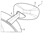
- FIG. 1 shows an exterior mirror, seen from behind, with a mirror head and a mirror foot upper part.
- FIG. 2 shows an exterior mirror, as seen from the front.
- FIG. 3 shows a view of the mirror foot upper part with the releasably connectable mirror foot lower part.
- FIG. 4 shows a view according to arrow A of the mirror foot parts.
- FIG. 5 shows a view of the mirror foot parts which are connected via a leaf spring.
- FIG. 6 shows a view of the mirror foot upper part with three bearing points and the leaf spring.
- FIG. 7 shows a view of the mirror foot upper part with the three bearing points and the inserted leaf spring.
- FIG. 8 shows a view of the mirror head lower part which is connected to the mirror head upper part.
- FIG. 9 shows a section according to the line IX-IX of FIG. 8 .
- FIG. 10 shows a section according to the line X-X of FIG. 8 .
- FIG. 11 shows a section according to the line XI-XI of FIG. 8 .
- FIG. 12 shows a section according to the line XII-XII of FIG. 8 .
- An exterior mirror 1 is mounted on a vehicle door 3 or on a door outer skin 3 b via a mirror foot upper part 4 and is connected separably to a mirror foot lower part 2 on which a mirror head 5 with a mirror surface 6 is held.
- the exterior mirror 1 legally is required to detach from the vehicle in the event of a “pendulum impact”.
- the mirror foot lower part 2 and the mirror foot upper part 4 are held together via a multi-point mounting 7 , 8 , 9 and are pressed together by a leaf spring 10 that is fastened to the mirror foot upper part 4 .
- the leaf spring 10 engages from above over a wall section 11 of the mirror foot lower part 2 .
- the mountings 7 , 8 and 9 between the mirror foot lower part 2 and the mirror foot upper part 4 form a longitudinally running connecting plane, that also defines a separating plane 12 along which the mirror foot parts 2 and 4 are separated from each in arrow direction P in the event of an impact.
- the separating plane 12 is arranged non-visibly within the door 3 in the door cavity 3 a , and no joints are visible on that section of the mirror foot upper part 4 from the outside, which is advantageous for optical reasons.
- the mirror foot lower part 2 is connected to an element 3 c of the door 3 and remains in the cavity 3 a of the door 3 after the mirror foot parts 2 and 4 are separated from each other.
- the multi-point mounting 7 , 8 , 9 on the mirror foot upper part 4 has local bearing points 13 , 14 and 15 each having a wedge-shaped depression 16 .
- Local bearing points 17 , 18 , 19 on the mirror foot lower part 2 have corresponding wedge-shaped projections 20 and engage the wedge-shaped depression 16 at the connecting position I.
- the bearing points 13 , 14 and 15 of the common bearings 7 , 8 and 9 with the wedge-shaped depression 16 are arranged on a bearing plate 21 of the mirror foot upper part 4 and the correspondingly arranged bearing points 17 , 18 , 19 with the wedge-shaped projections 20 are arranged on a holding plate 22 of the mirror foot lower part 2 .
- the bearing points are arranged at tips of an imaginary triangle.
- the two upper bearing points 13 , 15 of the bearing 7 on the mirror foot upper part 4 are spaced apart from one another in a common plane x-x and the two upper bearing points 17 , 18 of the bearing 8 on the mirror foot lower part 2 are spaced apart from one another in a common plane x-x.
- the upper bearing points 13 , 15 and 17 , 18 are oriented obliquely with respect to one another.
- the further bearing points 14 and 19 are located therebelow and are oriented upright in a vertical plane y-y.
- the bearing points 17 , 18 on the holding plate 22 of the mirror foot lower part 2 are bordered laterally in each case by offset limbs 24 , 25 of the holding plate 22 .
- the limbs 24 , 25 laterally support the bearing plate 21 of the mirror foot upper part 4 in the connecting position I of the mirror foot parts 2 and 4 .
- the leaf spring 10 on the mirror foot upper part 4 is arranged between the two upper bearing points 13 and 15 of the bearings 7 and 8 and is connected to the holding plate 22 via two screw bolts 26 .
- a free lower end 27 of the leaf spring 10 extends toward the lower bearing point 14 and engages over a prepared wall section 11 of the bearing plate 21 of the mirror foot lower part 2 in a clamping manner.
- the free end 27 of the leaf spring 10 is arranged and held in a pocket-shaped receptacle 30 .
- the wall section 11 of the holding plate 22 lies directly in the center of the three bearing points 17 , 18 and 19 of the holding plate of the mirror foot lower part 2 .
- the mirror foot upper part 4 is connected to the mirror foot lower part 2 via the mountings 7 , 8 , 9 within the cavity of the door 3 , and therefore the separating plane 12 is not visible from the outside and that part of the mirror foot upper part 4 which protrudes out of the door 3 via the door panel 3 b is joint-free.
Landscapes
- Engineering & Computer Science (AREA)
- Multimedia (AREA)
- Mechanical Engineering (AREA)
- Rear-View Mirror Devices That Are Mounted On The Exterior Of The Vehicle (AREA)
Abstract
Description
Claims (11)
Applications Claiming Priority (3)
| Application Number | Priority Date | Filing Date | Title |
|---|---|---|---|
| DE102012102440.5A DE102012102440B4 (en) | 2012-03-22 | 2012-03-22 | Outside mirror for a motor vehicle |
| DE102012102440 | 2012-03-22 | ||
| DE102012102440.5 | 2012-03-22 |
Publications (2)
| Publication Number | Publication Date |
|---|---|
| US20130250445A1 US20130250445A1 (en) | 2013-09-26 |
| US9045086B2 true US9045086B2 (en) | 2015-06-02 |
Family
ID=49112076
Family Applications (1)
| Application Number | Title | Priority Date | Filing Date |
|---|---|---|---|
| US13/848,951 Expired - Fee Related US9045086B2 (en) | 2012-03-22 | 2013-03-22 | Exterior mirror for a motor vehicle |
Country Status (3)
| Country | Link |
|---|---|
| US (1) | US9045086B2 (en) |
| DE (1) | DE102012102440B4 (en) |
| FR (1) | FR2988346B1 (en) |
Families Citing this family (4)
| Publication number | Priority date | Publication date | Assignee | Title |
|---|---|---|---|---|
| DE202014010293U1 (en) | 2014-03-28 | 2015-03-25 | Dr. Ing. H.C. F. Porsche Aktiengesellschaft | Exterior rearview mirror for a motor vehicle |
| DE202014010295U1 (en) | 2014-03-28 | 2015-04-01 | Dr. Ing. H.C. F. Porsche Aktiengesellschaft | Arrangement of a motor vehicle door and associated with this exterior rearview mirror |
| US11634079B2 (en) * | 2019-07-31 | 2023-04-25 | Tusimple, Inc. | Lidar mirror sensor assembly |
| DE102024122998A1 (en) * | 2024-08-12 | 2026-02-12 | Bayerische Motoren Werke Aktiengesellschaft | Motor vehicle with one exterior mirror |
Citations (3)
| Publication number | Priority date | Publication date | Assignee | Title |
|---|---|---|---|---|
| DE1266653B (en) | 1962-02-15 | 1968-04-18 | Yorck Talbot | Outside rearview mirror, especially for vehicles |
| DE7230111U (en) | 1972-11-02 | Hagus Metallwarenwerk Gmbh | Exterior mirrors for vehicles that spring off as a result of impact | |
| US20080088957A1 (en) * | 2005-05-04 | 2008-04-17 | Emmanuel Courbon | Mirror stabilizer arm connector assembly |
Family Cites Families (3)
| Publication number | Priority date | Publication date | Assignee | Title |
|---|---|---|---|---|
| DE10328657B4 (en) | 2003-04-17 | 2007-12-20 | Busch & Müller KG Fahrzeugteilefabrik | Rear-view mirror arrangement with rear-view mirror pivoting part |
| US7261272B2 (en) | 2005-05-18 | 2007-08-28 | Lang Mekra North America, Llc | Conical support arm joint for a vehicle mirror |
| DE102007032901A1 (en) | 2007-07-14 | 2009-01-15 | Dr. Ing. H.C. F. Porsche Aktiengesellschaft | Exterior rearview mirror for vehicles, in particular passenger cars |
-
2012
- 2012-03-22 DE DE102012102440.5A patent/DE102012102440B4/en not_active Expired - Fee Related
-
2013
- 2013-03-19 FR FR1352415A patent/FR2988346B1/en not_active Expired - Fee Related
- 2013-03-22 US US13/848,951 patent/US9045086B2/en not_active Expired - Fee Related
Patent Citations (3)
| Publication number | Priority date | Publication date | Assignee | Title |
|---|---|---|---|---|
| DE7230111U (en) | 1972-11-02 | Hagus Metallwarenwerk Gmbh | Exterior mirrors for vehicles that spring off as a result of impact | |
| DE1266653B (en) | 1962-02-15 | 1968-04-18 | Yorck Talbot | Outside rearview mirror, especially for vehicles |
| US20080088957A1 (en) * | 2005-05-04 | 2008-04-17 | Emmanuel Courbon | Mirror stabilizer arm connector assembly |
Also Published As
| Publication number | Publication date |
|---|---|
| US20130250445A1 (en) | 2013-09-26 |
| FR2988346B1 (en) | 2016-11-25 |
| DE102012102440B4 (en) | 2022-01-13 |
| DE102012102440A1 (en) | 2013-09-26 |
| FR2988346A1 (en) | 2013-09-27 |
Similar Documents
| Publication | Publication Date | Title |
|---|---|---|
| US9045086B2 (en) | Exterior mirror for a motor vehicle | |
| USD580313S1 (en) | Front portion of an automobile | |
| US9174577B2 (en) | Mount interface to slide on windscreen button | |
| USD621756S1 (en) | Truck rear fender panel | |
| USD594050S1 (en) | Adapter assembly for mounting a camera on a surgical microscope | |
| EP2045170A3 (en) | Front end structure for automobile | |
| WO2008093244A3 (en) | Vehicle end portion structure | |
| USD806623S1 (en) | Instrument panel for automobile | |
| CN103702868B (en) | The anchor fitting of the sensor element on self-propelled vehicle connecting element | |
| EP1806210A3 (en) | Travelling robot | |
| WO2008087346A3 (en) | Support mount for an impact-absorbing system intended to be mounted at the end of a motor vehicle side member | |
| DK2195195T3 (en) | Rearview mirror arrangement for vehicles | |
| USD547888S1 (en) | Headlamp housing | |
| JP2015525577A (en) | drawer | |
| USD602169S1 (en) | Door with frame | |
| USD595615S1 (en) | Motor vehicle and toy replica thereof | |
| USD590892S1 (en) | Sign support | |
| USD567155S1 (en) | Front portion of an automobile | |
| EP2017163A3 (en) | Vehicle body front part structure | |
| CN207758738U (en) | The mounting structure of bumper and wheel arch and the vehicle with it | |
| CN102862452B (en) | The cover plate of the functor stretched out at the body structure at the front side of motor vehicles or rear side | |
| EP2749828A3 (en) | Shelf assembly for refrigerator and refrigerator | |
| USD626887S1 (en) | Motor vehicle and toy replica thereof | |
| CN109398242A (en) | One kind is fixed to prevent abnormal sound clamping installation structure | |
| KR20140066118A (en) | Mirror head, in particular for an exterior vehicle mirror |
Legal Events
| Date | Code | Title | Description |
|---|---|---|---|
| AS | Assignment |
Owner name: DR. ING. H.C. F. PORSCHE AKTIENGESELLSCHAFT, GERMA Free format text: ASSIGNMENT OF ASSIGNORS INTEREST;ASSIGNOR:MUELLER, MARCUS;REEL/FRAME:030132/0715 Effective date: 20130328 |
|
| STCF | Information on status: patent grant |
Free format text: PATENTED CASE |
|
| FEPP | Fee payment procedure |
Free format text: PAYOR NUMBER ASSIGNED (ORIGINAL EVENT CODE: ASPN); ENTITY STATUS OF PATENT OWNER: LARGE ENTITY |
|
| MAFP | Maintenance fee payment |
Free format text: PAYMENT OF MAINTENANCE FEE, 4TH YEAR, LARGE ENTITY (ORIGINAL EVENT CODE: M1551); ENTITY STATUS OF PATENT OWNER: LARGE ENTITY Year of fee payment: 4 |
|
| FEPP | Fee payment procedure |
Free format text: MAINTENANCE FEE REMINDER MAILED (ORIGINAL EVENT CODE: REM.); ENTITY STATUS OF PATENT OWNER: LARGE ENTITY |
|
| LAPS | Lapse for failure to pay maintenance fees |
Free format text: PATENT EXPIRED FOR FAILURE TO PAY MAINTENANCE FEES (ORIGINAL EVENT CODE: EXP.); ENTITY STATUS OF PATENT OWNER: LARGE ENTITY |
|
| STCH | Information on status: patent discontinuation |
Free format text: PATENT EXPIRED DUE TO NONPAYMENT OF MAINTENANCE FEES UNDER 37 CFR 1.362 |
|
| FP | Lapsed due to failure to pay maintenance fee |
Effective date: 20230602 |