US9040143B2 - Low-E housewrap - Google Patents
Low-E housewrap Download PDFInfo
- Publication number
- US9040143B2 US9040143B2 US13/107,568 US201113107568A US9040143B2 US 9040143 B2 US9040143 B2 US 9040143B2 US 201113107568 A US201113107568 A US 201113107568A US 9040143 B2 US9040143 B2 US 9040143B2
- Authority
- US
- United States
- Prior art keywords
- flexible insulation
- base insulating
- low
- insulating material
- perforations
- Prior art date
- Legal status (The legal status is an assumption and is not a legal conclusion. Google has not performed a legal analysis and makes no representation as to the accuracy of the status listed.)
- Active
Links
- 239000000463 material Substances 0.000 claims abstract description 108
- XLYOFNOQVPJJNP-UHFFFAOYSA-N water Substances O XLYOFNOQVPJJNP-UHFFFAOYSA-N 0.000 claims abstract description 22
- 230000004888 barrier function Effects 0.000 claims abstract description 16
- 238000009413 insulation Methods 0.000 claims description 44
- 239000000853 adhesive Substances 0.000 claims description 13
- 230000001070 adhesive effect Effects 0.000 claims description 13
- 230000002787 reinforcement Effects 0.000 claims description 13
- 239000006260 foam Substances 0.000 claims description 12
- 229910052782 aluminium Inorganic materials 0.000 claims description 9
- XAGFODPZIPBFFR-UHFFFAOYSA-N aluminium Chemical compound [Al] XAGFODPZIPBFFR-UHFFFAOYSA-N 0.000 claims description 9
- -1 polyethylene Polymers 0.000 claims description 8
- 239000004698 Polyethylene Substances 0.000 claims description 7
- 229920000573 polyethylene Polymers 0.000 claims description 7
- 230000005540 biological transmission Effects 0.000 claims description 6
- 229920000098 polyolefin Polymers 0.000 claims description 6
- 230000001681 protective effect Effects 0.000 claims description 5
- 238000010998 test method Methods 0.000 claims description 4
- 239000011810 insulating material Substances 0.000 claims 18
- 239000012779 reinforcing material Substances 0.000 claims 4
- 230000008595 infiltration Effects 0.000 abstract description 12
- 238000001764 infiltration Methods 0.000 abstract description 12
- 238000009432 framing Methods 0.000 abstract description 11
- 239000012774 insulation material Substances 0.000 abstract description 2
- 239000011888 foil Substances 0.000 description 16
- 238000000034 method Methods 0.000 description 9
- 239000000047 product Substances 0.000 description 7
- 239000011449 brick Substances 0.000 description 6
- 238000009434 installation Methods 0.000 description 6
- 238000010276 construction Methods 0.000 description 5
- 239000002023 wood Substances 0.000 description 4
- 230000033228 biological regulation Effects 0.000 description 3
- 239000006261 foam material Substances 0.000 description 3
- 239000004575 stone Substances 0.000 description 3
- 229920000690 Tyvek Polymers 0.000 description 2
- 238000009435 building construction Methods 0.000 description 2
- 239000007795 chemical reaction product Substances 0.000 description 2
- 238000005336 cracking Methods 0.000 description 2
- 230000003014 reinforcing effect Effects 0.000 description 2
- 238000005728 strengthening Methods 0.000 description 2
- 125000000391 vinyl group Chemical group [H]C([*])=C([H])[H] 0.000 description 2
- 229920002554 vinyl polymer Polymers 0.000 description 2
- 239000004743 Polypropylene Substances 0.000 description 1
- 239000004775 Tyvek Substances 0.000 description 1
- 230000032683 aging Effects 0.000 description 1
- 230000000712 assembly Effects 0.000 description 1
- 238000000429 assembly Methods 0.000 description 1
- 239000004035 construction material Substances 0.000 description 1
- 238000004134 energy conservation Methods 0.000 description 1
- 230000007613 environmental effect Effects 0.000 description 1
- 238000011156 evaluation Methods 0.000 description 1
- 230000014759 maintenance of location Effects 0.000 description 1
- 229910052751 metal Inorganic materials 0.000 description 1
- 239000002184 metal Substances 0.000 description 1
- 230000035515 penetration Effects 0.000 description 1
- 239000004033 plastic Substances 0.000 description 1
- 229920003023 plastic Polymers 0.000 description 1
- 229920001155 polypropylene Polymers 0.000 description 1
- 239000000126 substance Substances 0.000 description 1
Images


Classifications
-
- E—FIXED CONSTRUCTIONS
- E04—BUILDING
- E04B—GENERAL BUILDING CONSTRUCTIONS; WALLS, e.g. PARTITIONS; ROOFS; FLOORS; CEILINGS; INSULATION OR OTHER PROTECTION OF BUILDINGS
- E04B1/00—Constructions in general; Structures which are not restricted either to walls, e.g. partitions, or floors or ceilings or roofs
- E04B1/62—Insulation or other protection; Elements or use of specified material therefor
- E04B1/625—Sheets or foils allowing passage of water vapor but impervious to liquid water; house wraps
-
- E—FIXED CONSTRUCTIONS
- E04—BUILDING
- E04B—GENERAL BUILDING CONSTRUCTIONS; WALLS, e.g. PARTITIONS; ROOFS; FLOORS; CEILINGS; INSULATION OR OTHER PROTECTION OF BUILDINGS
- E04B1/00—Constructions in general; Structures which are not restricted either to walls, e.g. partitions, or floors or ceilings or roofs
- E04B1/62—Insulation or other protection; Elements or use of specified material therefor
-
- B—PERFORMING OPERATIONS; TRANSPORTING
- B32—LAYERED PRODUCTS
- B32B—LAYERED PRODUCTS, i.e. PRODUCTS BUILT-UP OF STRATA OF FLAT OR NON-FLAT, e.g. CELLULAR OR HONEYCOMB, FORM
- B32B13/00—Layered products comprising a a layer of water-setting substance, e.g. concrete, plaster, asbestos cement, or like builders' material
-
- B—PERFORMING OPERATIONS; TRANSPORTING
- B32—LAYERED PRODUCTS
- B32B—LAYERED PRODUCTS, i.e. PRODUCTS BUILT-UP OF STRATA OF FLAT OR NON-FLAT, e.g. CELLULAR OR HONEYCOMB, FORM
- B32B15/00—Layered products comprising a layer of metal
- B32B15/04—Layered products comprising a layer of metal comprising metal as the main or only constituent of a layer, which is next to another layer of the same or of a different material
- B32B15/046—Layered products comprising a layer of metal comprising metal as the main or only constituent of a layer, which is next to another layer of the same or of a different material of foam
-
- B—PERFORMING OPERATIONS; TRANSPORTING
- B32—LAYERED PRODUCTS
- B32B—LAYERED PRODUCTS, i.e. PRODUCTS BUILT-UP OF STRATA OF FLAT OR NON-FLAT, e.g. CELLULAR OR HONEYCOMB, FORM
- B32B15/00—Layered products comprising a layer of metal
- B32B15/04—Layered products comprising a layer of metal comprising metal as the main or only constituent of a layer, which is next to another layer of the same or of a different material
- B32B15/08—Layered products comprising a layer of metal comprising metal as the main or only constituent of a layer, which is next to another layer of the same or of a different material of synthetic resin
- B32B15/085—Layered products comprising a layer of metal comprising metal as the main or only constituent of a layer, which is next to another layer of the same or of a different material of synthetic resin comprising polyolefins
-
- B—PERFORMING OPERATIONS; TRANSPORTING
- B32—LAYERED PRODUCTS
- B32B—LAYERED PRODUCTS, i.e. PRODUCTS BUILT-UP OF STRATA OF FLAT OR NON-FLAT, e.g. CELLULAR OR HONEYCOMB, FORM
- B32B15/00—Layered products comprising a layer of metal
- B32B15/14—Layered products comprising a layer of metal next to a fibrous or filamentary layer
-
- B—PERFORMING OPERATIONS; TRANSPORTING
- B32—LAYERED PRODUCTS
- B32B—LAYERED PRODUCTS, i.e. PRODUCTS BUILT-UP OF STRATA OF FLAT OR NON-FLAT, e.g. CELLULAR OR HONEYCOMB, FORM
- B32B15/00—Layered products comprising a layer of metal
- B32B15/20—Layered products comprising a layer of metal comprising aluminium or copper
-
- B—PERFORMING OPERATIONS; TRANSPORTING
- B32—LAYERED PRODUCTS
- B32B—LAYERED PRODUCTS, i.e. PRODUCTS BUILT-UP OF STRATA OF FLAT OR NON-FLAT, e.g. CELLULAR OR HONEYCOMB, FORM
- B32B27/00—Layered products comprising a layer of synthetic resin
- B32B27/06—Layered products comprising a layer of synthetic resin as the main or only constituent of a layer, which is next to another layer of the same or of a different material
- B32B27/08—Layered products comprising a layer of synthetic resin as the main or only constituent of a layer, which is next to another layer of the same or of a different material of synthetic resin
-
- B—PERFORMING OPERATIONS; TRANSPORTING
- B32—LAYERED PRODUCTS
- B32B—LAYERED PRODUCTS, i.e. PRODUCTS BUILT-UP OF STRATA OF FLAT OR NON-FLAT, e.g. CELLULAR OR HONEYCOMB, FORM
- B32B27/00—Layered products comprising a layer of synthetic resin
- B32B27/12—Layered products comprising a layer of synthetic resin next to a fibrous or filamentary layer
-
- B—PERFORMING OPERATIONS; TRANSPORTING
- B32—LAYERED PRODUCTS
- B32B—LAYERED PRODUCTS, i.e. PRODUCTS BUILT-UP OF STRATA OF FLAT OR NON-FLAT, e.g. CELLULAR OR HONEYCOMB, FORM
- B32B27/00—Layered products comprising a layer of synthetic resin
- B32B27/32—Layered products comprising a layer of synthetic resin comprising polyolefins
-
- B—PERFORMING OPERATIONS; TRANSPORTING
- B32—LAYERED PRODUCTS
- B32B—LAYERED PRODUCTS, i.e. PRODUCTS BUILT-UP OF STRATA OF FLAT OR NON-FLAT, e.g. CELLULAR OR HONEYCOMB, FORM
- B32B3/00—Layered products comprising a layer with external or internal discontinuities or unevennesses, or a layer of non-planar form; Layered products having particular features of form
- B32B3/02—Layered products comprising a layer with external or internal discontinuities or unevennesses, or a layer of non-planar form; Layered products having particular features of form characterised by features of form at particular places, e.g. in edge regions
-
- B—PERFORMING OPERATIONS; TRANSPORTING
- B32—LAYERED PRODUCTS
- B32B—LAYERED PRODUCTS, i.e. PRODUCTS BUILT-UP OF STRATA OF FLAT OR NON-FLAT, e.g. CELLULAR OR HONEYCOMB, FORM
- B32B3/00—Layered products comprising a layer with external or internal discontinuities or unevennesses, or a layer of non-planar form; Layered products having particular features of form
- B32B3/26—Layered products comprising a layer with external or internal discontinuities or unevennesses, or a layer of non-planar form; Layered products having particular features of form characterised by a particular shape of the outline of the cross-section of a continuous layer; characterised by a layer with cavities or internal voids ; characterised by an apertured layer
- B32B3/266—Layered products comprising a layer with external or internal discontinuities or unevennesses, or a layer of non-planar form; Layered products having particular features of form characterised by a particular shape of the outline of the cross-section of a continuous layer; characterised by a layer with cavities or internal voids ; characterised by an apertured layer characterised by an apertured layer, the apertures going through the whole thickness of the layer, e.g. expanded metal, perforated layer, slit layer regular cells B32B3/12
-
- B—PERFORMING OPERATIONS; TRANSPORTING
- B32—LAYERED PRODUCTS
- B32B—LAYERED PRODUCTS, i.e. PRODUCTS BUILT-UP OF STRATA OF FLAT OR NON-FLAT, e.g. CELLULAR OR HONEYCOMB, FORM
- B32B37/00—Methods or apparatus for laminating, e.g. by curing or by ultrasonic bonding
- B32B37/02—Methods or apparatus for laminating, e.g. by curing or by ultrasonic bonding characterised by a sequence of laminating steps, e.g. by adding new layers at consecutive laminating stations
-
- B—PERFORMING OPERATIONS; TRANSPORTING
- B32—LAYERED PRODUCTS
- B32B—LAYERED PRODUCTS, i.e. PRODUCTS BUILT-UP OF STRATA OF FLAT OR NON-FLAT, e.g. CELLULAR OR HONEYCOMB, FORM
- B32B38/00—Ancillary operations in connection with laminating processes
- B32B38/04—Punching, slitting or perforating
-
- B—PERFORMING OPERATIONS; TRANSPORTING
- B32—LAYERED PRODUCTS
- B32B—LAYERED PRODUCTS, i.e. PRODUCTS BUILT-UP OF STRATA OF FLAT OR NON-FLAT, e.g. CELLULAR OR HONEYCOMB, FORM
- B32B5/00—Layered products characterised by the non- homogeneity or physical structure, i.e. comprising a fibrous, filamentary, particulate or foam layer; Layered products characterised by having a layer differing constitutionally or physically in different parts
- B32B5/02—Layered products characterised by the non- homogeneity or physical structure, i.e. comprising a fibrous, filamentary, particulate or foam layer; Layered products characterised by having a layer differing constitutionally or physically in different parts characterised by structural features of a fibrous or filamentary layer
- B32B5/028—Net structure, e.g. spaced apart filaments bonded at the crossing points
-
- B—PERFORMING OPERATIONS; TRANSPORTING
- B32—LAYERED PRODUCTS
- B32B—LAYERED PRODUCTS, i.e. PRODUCTS BUILT-UP OF STRATA OF FLAT OR NON-FLAT, e.g. CELLULAR OR HONEYCOMB, FORM
- B32B5/00—Layered products characterised by the non- homogeneity or physical structure, i.e. comprising a fibrous, filamentary, particulate or foam layer; Layered products characterised by having a layer differing constitutionally or physically in different parts
- B32B5/18—Layered products characterised by the non- homogeneity or physical structure, i.e. comprising a fibrous, filamentary, particulate or foam layer; Layered products characterised by having a layer differing constitutionally or physically in different parts characterised by features of a layer of foamed material
-
- B—PERFORMING OPERATIONS; TRANSPORTING
- B32—LAYERED PRODUCTS
- B32B—LAYERED PRODUCTS, i.e. PRODUCTS BUILT-UP OF STRATA OF FLAT OR NON-FLAT, e.g. CELLULAR OR HONEYCOMB, FORM
- B32B7/00—Layered products characterised by the relation between layers; Layered products characterised by the relative orientation of features between layers, or by the relative values of a measurable parameter between layers, i.e. products comprising layers having different physical, chemical or physicochemical properties; Layered products characterised by the interconnection of layers
- B32B7/04—Interconnection of layers
- B32B7/12—Interconnection of layers using interposed adhesives or interposed materials with bonding properties
-
- E—FIXED CONSTRUCTIONS
- E04—BUILDING
- E04B—GENERAL BUILDING CONSTRUCTIONS; WALLS, e.g. PARTITIONS; ROOFS; FLOORS; CEILINGS; INSULATION OR OTHER PROTECTION OF BUILDINGS
- E04B1/00—Constructions in general; Structures which are not restricted either to walls, e.g. partitions, or floors or ceilings or roofs
- E04B1/62—Insulation or other protection; Elements or use of specified material therefor
- E04B1/74—Heat, sound or noise insulation, absorption, or reflection; Other building methods affording favourable thermal or acoustical conditions, e.g. accumulating of heat within walls
- E04B1/76—Heat, sound or noise insulation, absorption, or reflection; Other building methods affording favourable thermal or acoustical conditions, e.g. accumulating of heat within walls specifically with respect to heat only
-
- B—PERFORMING OPERATIONS; TRANSPORTING
- B32—LAYERED PRODUCTS
- B32B—LAYERED PRODUCTS, i.e. PRODUCTS BUILT-UP OF STRATA OF FLAT OR NON-FLAT, e.g. CELLULAR OR HONEYCOMB, FORM
- B32B38/00—Ancillary operations in connection with laminating processes
- B32B38/04—Punching, slitting or perforating
- B32B2038/047—Perforating
-
- B—PERFORMING OPERATIONS; TRANSPORTING
- B32—LAYERED PRODUCTS
- B32B—LAYERED PRODUCTS, i.e. PRODUCTS BUILT-UP OF STRATA OF FLAT OR NON-FLAT, e.g. CELLULAR OR HONEYCOMB, FORM
- B32B2266/00—Composition of foam
- B32B2266/02—Organic
- B32B2266/0214—Materials belonging to B32B27/00
- B32B2266/025—Polyolefin
-
- B—PERFORMING OPERATIONS; TRANSPORTING
- B32—LAYERED PRODUCTS
- B32B—LAYERED PRODUCTS, i.e. PRODUCTS BUILT-UP OF STRATA OF FLAT OR NON-FLAT, e.g. CELLULAR OR HONEYCOMB, FORM
- B32B2266/00—Composition of foam
- B32B2266/08—Closed cell foam
-
- B—PERFORMING OPERATIONS; TRANSPORTING
- B32—LAYERED PRODUCTS
- B32B—LAYERED PRODUCTS, i.e. PRODUCTS BUILT-UP OF STRATA OF FLAT OR NON-FLAT, e.g. CELLULAR OR HONEYCOMB, FORM
- B32B2305/00—Condition, form or state of the layers or laminate
- B32B2305/02—Cellular or porous
- B32B2305/022—Foam
-
- B—PERFORMING OPERATIONS; TRANSPORTING
- B32—LAYERED PRODUCTS
- B32B—LAYERED PRODUCTS, i.e. PRODUCTS BUILT-UP OF STRATA OF FLAT OR NON-FLAT, e.g. CELLULAR OR HONEYCOMB, FORM
- B32B2307/00—Properties of the layers or laminate
- B32B2307/30—Properties of the layers or laminate having particular thermal properties
- B32B2307/304—Insulating
-
- B—PERFORMING OPERATIONS; TRANSPORTING
- B32—LAYERED PRODUCTS
- B32B—LAYERED PRODUCTS, i.e. PRODUCTS BUILT-UP OF STRATA OF FLAT OR NON-FLAT, e.g. CELLULAR OR HONEYCOMB, FORM
- B32B2307/00—Properties of the layers or laminate
- B32B2307/40—Properties of the layers or laminate having particular optical properties
- B32B2307/416—Reflective
-
- B—PERFORMING OPERATIONS; TRANSPORTING
- B32—LAYERED PRODUCTS
- B32B—LAYERED PRODUCTS, i.e. PRODUCTS BUILT-UP OF STRATA OF FLAT OR NON-FLAT, e.g. CELLULAR OR HONEYCOMB, FORM
- B32B2307/00—Properties of the layers or laminate
- B32B2307/50—Properties of the layers or laminate having particular mechanical properties
- B32B2307/54—Yield strength; Tensile strength
-
- B—PERFORMING OPERATIONS; TRANSPORTING
- B32—LAYERED PRODUCTS
- B32B—LAYERED PRODUCTS, i.e. PRODUCTS BUILT-UP OF STRATA OF FLAT OR NON-FLAT, e.g. CELLULAR OR HONEYCOMB, FORM
- B32B2307/00—Properties of the layers or laminate
- B32B2307/50—Properties of the layers or laminate having particular mechanical properties
- B32B2307/582—Tearability
- B32B2307/5825—Tear resistant
-
- B—PERFORMING OPERATIONS; TRANSPORTING
- B32—LAYERED PRODUCTS
- B32B—LAYERED PRODUCTS, i.e. PRODUCTS BUILT-UP OF STRATA OF FLAT OR NON-FLAT, e.g. CELLULAR OR HONEYCOMB, FORM
- B32B2307/00—Properties of the layers or laminate
- B32B2307/70—Other properties
- B32B2307/724—Permeability to gases, adsorption
- B32B2307/7242—Non-permeable
- B32B2307/7246—Water vapor barrier
-
- B—PERFORMING OPERATIONS; TRANSPORTING
- B32—LAYERED PRODUCTS
- B32B—LAYERED PRODUCTS, i.e. PRODUCTS BUILT-UP OF STRATA OF FLAT OR NON-FLAT, e.g. CELLULAR OR HONEYCOMB, FORM
- B32B2311/00—Metals, their alloys or their compounds
- B32B2311/24—Aluminium
-
- B—PERFORMING OPERATIONS; TRANSPORTING
- B32—LAYERED PRODUCTS
- B32B—LAYERED PRODUCTS, i.e. PRODUCTS BUILT-UP OF STRATA OF FLAT OR NON-FLAT, e.g. CELLULAR OR HONEYCOMB, FORM
- B32B2355/00—Specific polymers obtained by polymerisation reactions only involving carbon-to-carbon unsaturated bonds, not provided for in a single one of index codes B32B2323/00 - B32B2333/00
-
- B—PERFORMING OPERATIONS; TRANSPORTING
- B32—LAYERED PRODUCTS
- B32B—LAYERED PRODUCTS, i.e. PRODUCTS BUILT-UP OF STRATA OF FLAT OR NON-FLAT, e.g. CELLULAR OR HONEYCOMB, FORM
- B32B2405/00—Adhesive articles, e.g. adhesive tapes
-
- B—PERFORMING OPERATIONS; TRANSPORTING
- B32—LAYERED PRODUCTS
- B32B—LAYERED PRODUCTS, i.e. PRODUCTS BUILT-UP OF STRATA OF FLAT OR NON-FLAT, e.g. CELLULAR OR HONEYCOMB, FORM
- B32B2419/00—Buildings or parts thereof
-
- B—PERFORMING OPERATIONS; TRANSPORTING
- B32—LAYERED PRODUCTS
- B32B—LAYERED PRODUCTS, i.e. PRODUCTS BUILT-UP OF STRATA OF FLAT OR NON-FLAT, e.g. CELLULAR OR HONEYCOMB, FORM
- B32B2607/00—Walls, panels
-
- E—FIXED CONSTRUCTIONS
- E04—BUILDING
- E04B—GENERAL BUILDING CONSTRUCTIONS; WALLS, e.g. PARTITIONS; ROOFS; FLOORS; CEILINGS; INSULATION OR OTHER PROTECTION OF BUILDINGS
- E04B1/00—Constructions in general; Structures which are not restricted either to walls, e.g. partitions, or floors or ceilings or roofs
- E04B1/62—Insulation or other protection; Elements or use of specified material therefor
- E04B1/74—Heat, sound or noise insulation, absorption, or reflection; Other building methods affording favourable thermal or acoustical conditions, e.g. accumulating of heat within walls
- E04B1/76—Heat, sound or noise insulation, absorption, or reflection; Other building methods affording favourable thermal or acoustical conditions, e.g. accumulating of heat within walls specifically with respect to heat only
- E04B2001/7691—Heat reflecting layers or coatings
-
- Y—GENERAL TAGGING OF NEW TECHNOLOGICAL DEVELOPMENTS; GENERAL TAGGING OF CROSS-SECTIONAL TECHNOLOGIES SPANNING OVER SEVERAL SECTIONS OF THE IPC; TECHNICAL SUBJECTS COVERED BY FORMER USPC CROSS-REFERENCE ART COLLECTIONS [XRACs] AND DIGESTS
- Y02—TECHNOLOGIES OR APPLICATIONS FOR MITIGATION OR ADAPTATION AGAINST CLIMATE CHANGE
- Y02A—TECHNOLOGIES FOR ADAPTATION TO CLIMATE CHANGE
- Y02A30/00—Adapting or protecting infrastructure or their operation
-
- Y—GENERAL TAGGING OF NEW TECHNOLOGICAL DEVELOPMENTS; GENERAL TAGGING OF CROSS-SECTIONAL TECHNOLOGIES SPANNING OVER SEVERAL SECTIONS OF THE IPC; TECHNICAL SUBJECTS COVERED BY FORMER USPC CROSS-REFERENCE ART COLLECTIONS [XRACs] AND DIGESTS
- Y02—TECHNOLOGIES OR APPLICATIONS FOR MITIGATION OR ADAPTATION AGAINST CLIMATE CHANGE
- Y02B—CLIMATE CHANGE MITIGATION TECHNOLOGIES RELATED TO BUILDINGS, e.g. HOUSING, HOUSE APPLIANCES OR RELATED END-USER APPLICATIONS
- Y02B30/00—Energy efficient heating, ventilation or air conditioning [HVAC]
- Y02B30/90—Passive houses; Double facade technology
-
- Y—GENERAL TAGGING OF NEW TECHNOLOGICAL DEVELOPMENTS; GENERAL TAGGING OF CROSS-SECTIONAL TECHNOLOGIES SPANNING OVER SEVERAL SECTIONS OF THE IPC; TECHNICAL SUBJECTS COVERED BY FORMER USPC CROSS-REFERENCE ART COLLECTIONS [XRACs] AND DIGESTS
- Y10—TECHNICAL SUBJECTS COVERED BY FORMER USPC
- Y10T—TECHNICAL SUBJECTS COVERED BY FORMER US CLASSIFICATION
- Y10T156/00—Adhesive bonding and miscellaneous chemical manufacture
- Y10T156/10—Methods of surface bonding and/or assembly therefor
- Y10T156/1052—Methods of surface bonding and/or assembly therefor with cutting, punching, tearing or severing
- Y10T156/1056—Perforating lamina
- Y10T156/1057—Subsequent to assembly of laminae
-
- Y—GENERAL TAGGING OF NEW TECHNOLOGICAL DEVELOPMENTS; GENERAL TAGGING OF CROSS-SECTIONAL TECHNOLOGIES SPANNING OVER SEVERAL SECTIONS OF THE IPC; TECHNICAL SUBJECTS COVERED BY FORMER USPC CROSS-REFERENCE ART COLLECTIONS [XRACs] AND DIGESTS
- Y10—TECHNICAL SUBJECTS COVERED BY FORMER USPC
- Y10T—TECHNICAL SUBJECTS COVERED BY FORMER US CLASSIFICATION
- Y10T428/00—Stock material or miscellaneous articles
- Y10T428/24—Structurally defined web or sheet [e.g., overall dimension, etc.]
- Y10T428/24273—Structurally defined web or sheet [e.g., overall dimension, etc.] including aperture
- Y10T428/24322—Composite web or sheet
- Y10T428/24331—Composite web or sheet including nonapertured component
Definitions
- the present invention relates generally to building structure materials, and more specifically to an infiltration barrier used in building construction to improve energy efficiency and to protect against air infiltration and moisture build-up in buildings.
- infiltration barrier In order to improve the energy efficiency of new and existing buildings, it has been common practice in building new structures, and in residing old structures, to cover the exterior wall sheathing with an infiltration barrier, for example, prior to installation of a covering material such as siding.
- an infiltration barrier is a high density polyethylene fiber sheeting. While infiltration barriers cut down on drafts and thereby convective heat loss, they provide little other contribution to the energy efficiency of the structure.
- a weather resistant barrier has for many years been applied to the wood studs of buildings and homes in order to resist the moisture or water generated by weather. Such material is typically flexible and in a film or sheet form. Typically, this weather resistant barrier or “house wrap” is applied to the wooden stud frame before the application of a final siding or veneer (e.g. brick, metal, painted wood). Many such “wrap” products are commercially available such as, for example: Dupont Tyvek®, Typar®. Housewrap (www.typarhousewrap.com), and Barricade®, building wrap (www.ludlowcp.com).
- the International Energy Conservation Code (IECC) and International Residential Code (IRC) increased the thermal performance requirements for residential walls. Both of these standards seek to improve thermal performance and reduce energy needs per dwelling.
- the U-value requirement for geographical area or zones 5-8 is 0.057; the reciprocal R-value for wall systems is R-20.
- the R-Value is the thermal resistance to heat flow.
- a larger R-Value means that the material has greater thermal resistance and more insulating ability as compared to a smaller R-Value.
- Such R-Values can be added together.
- the total R-Value of an insulation assembly is the sum of the R-Value of each layer of insulation. These layers may include sheathing and finishes, the insulation itself, air films and weatherproofing elements.
- builders In order to meet the new building requirements, builders have employed additional building techniques such as altering construction of framed openings. For example, typically, builders have constructed walls on 2 ⁇ 4 framing. However, due to the revised requirements, builders are altering building designs by constructing walls on 2 ⁇ 6 framing and inserting, for example, R-20 mass insulation within the respective wall cavity in order to meet the energy/code regulations mandated within the building industry. These techniques, however, increase construction costs because of the added and more expensive construction materials. In addition, the increased size of framing also produces a loss in living space. Nevertheless, many builders have simply accepted the added cost and loss of living space created by the newly implemented thermal code changes.
- a protective wrap which meets or exceeds the newly implemented code requirements on existing framing structures or openings and/or without increasing the wall profile of a building.
- the present invention provides a low-E housewrap material which may be implemented on traditional 2 ⁇ 4 framing having R-15 mass insulation material within existing or newly constructed framing cavities.
- the material of the present invention also meets requirements for serving as a water resistive barrier as defined by The International Code Council's (ICC) codes and standards used to construct residential and commercial buildings, including homes and schools (e.g., ICC AC38).
- ICC International Code Council's
- FIG. 1 provides a top view of a low-E housewrap material according to an exemplary disclosed embodiment
- FIG. 2 provides a cross-sectional view of a low-E housewrap material according to an exemplary disclosed embodiment
- FIG. 3 provides a cut-away perspective view of a low-E housewrap material according to an exemplary disclosed embodiment
- FIG. 4 provides a top view of a low-E housewrap materials during an assembly method according to an exemplary disclosed embodiment
- FIG. 5 provides a perspective view of the low-E housewrap materials during the assembly method of FIG. 4 ;
- FIG. 6 provides a top view of a low-E housewrap materials during a continued assembly method according to an exemplary disclosed embodiment
- FIG. 7 provides a perspective view of the low-E housewrap materials during the assembly method of FIG. 6 ;
- FIG. 8 provides a top view of low-E housewrap materials after assembly according to an exemplary disclosed embodiment
- FIG. 9 provides a bottom view of low-E housewrap materials prior to assembly according to an exemplary disclosed embodiment
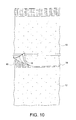
- FIG. 10 provides a top view of low-E housewrap materials during an assembly method according to an exemplary disclosed embodiment
- FIG. 11 provides a bottom view of low-E housewrap materials after assembly according to an exemplary disclosed embodiment
- FIG. 12 provides an exemplary exterior wall according to an exemplary disclosed embodiment
- FIG. 13 provides a low-E housewrap material application to the exemplary wall structure of FIG. 12 . according to an exemplary disclosed embodiment.
- FIG. 1 illustrates a top view of low-E housewrap materials according to one disclosed embodiment of the present invention.
- two pieces of the low-E housewrap materials 10 , 12 are shown.
- Each of the two pieces of low-E housewrap materials 10 , 12 may comprise flap portions 14 , 16 , respectively, at one end thereof.
- the low-E housewrap material may include an adhesive strip 18 such as that provided on low-E housewrap material 10 .
- the top surface 20 , 22 of the low-E housewrap materials 10 , 12 is a reflective material such as a layer of reinforced foil material.
- the low-E housewrap material 12 may comprise an assembly of product component parts including, for example, a reflective foil material 34 , foil reinforcement 26 , and a foam material 28 .
- the reflective material may comprise a facing of approximately 99.4% polished aluminum. It is noted that the reflective material may comprise a facing having any suitable amount of aluminum, for example, greater than about 90%, preferably between about 90% and about 99.9%, even more preferably between about 99.0% and about 99.9%.
- the reflective foil material 34 may be non reinforced on one side.
- the reflective foil material 34 may comprise a foil reinforcement 26 including, for example, a scrim foil reinforcing 30 (e.g., see FIG. 3 ).
- Scrim is a term known in the art to consist of crossed lines of plastics material which serve to strengthen the overall product and to prevent stretching damage to the layers.
- the reflective foil material 34 and foil reinforcement 26 may be applied over and bonded to the foam material 28 .
- the scrim foil reinforcing 30 is sufficient to provide a tensile strength of approximately 23 pounds per inch width in a machine direction and 25 pounds per inch width in a cross machine direction on a low-E housewrap material test specimen cut approximately 1′′ wide by 9′′ long in standard ambient lab conditions.
- the foam material 28 serves as a polyolefin thermal break such as one comprising a closed cell polyethylene foam.
- the nominal thickness of the polyolefin thermal break is approximately 1 ⁇ 4′′ (0.25′′). It is noted that the nominal thickness of the polyolefin thermal break may be any suitable thickness, for example, greater than about 1 ⁇ 8′′ (0.125′′) and less than about 3 ⁇ 8′′ (0.375′′). Thicknesses above about 1 ⁇ 4′′ are within the scope of the present invention. It is noted that a thickness greater than about 1 ⁇ 4′′ may require use of 2 ⁇ 6 framing instead of the more traditional 2 ⁇ 4 framing.
- the low-E housewrap 12 may also incorporate a self adhered drainage plane 24 feature as further described below.
- the invention includes a layer of polyethylene foam which serves as a support for the other added component layers.
- Polyethylene foam or equivalent polypropylene foam may be utilized, both being in the chemical family designated as polyolefins.
- a thin layer of aluminum foil is bonded indirectly to one or both sides of said foam layer. Thin polyethylene layers are placed between the aluminum foil and the foamed layer. The thin polyethylene is bonded to the aluminum foil layer to greatly improve its resistance to tearing.
- This strengthening feature means that the end product has a much wider use than has been known in the art.
- a layer of strengthening scrim may be added to further enhance the product integrity. In practice of the invention, the various layers adjoin one another after being flame or heat roller laminated together.
- both sides of the foam layer may be covered with layers as described above.
- the end product may thus appear identical on either side with the aluminum foil layers being externally located.
- use and installation is simplified since the product may be used with either side facing out since both external faces are identical.
- the resulting bonded layers are easily rolled, transported and installed without requiring special tools or environmental precautions which must be taken with many other prior art insulations.
- the low-E housewrap 12 comprises perforations 32 sufficiently spaced to ensure that the low-E housewrap material does not act as a vapor barrier.
- the perforations in the low-E housewrap are generated from perforation system consisting of 1/16′′ punchers placed in four holes per 1.25 square inch sequence on a collar mechanism.
- the collar mechanism is mounted to a drive roll assembly for perforation of the low-E housewrap wherein a 1.25 square inch perforation pattern is achieved on the finished product.
- a perforation pattern of 1.25 square inch allows low-E housewrap 12 to meet the criteria for perms, water vapor transmission and water resistance while maintaining an effective emissivity rating.
- the low-E housewrap material achieves a preferred permeance and water vapor transmission of approximately 7 perm or 40 g/day/m 2 . As such, the present low-E housewrap material performs within the optimal permeance and water vapor transmission range of about 5 to about 20 perm.
- the present low-E housewrap material meets the Standard Specification for Reflective Insulation, C 1224-03, Section 6, 6.1, which states that “Low emittance materials shall have a surface with an emittance of 0.10 or less, in accordance with test Method C 1371.” Specifically, the present low-E housewrap material achieves an emittance of 0.10 or less, more specifically within a range of about 0.03 to about 0.05, in accordance with test Method C 1371.
- the product low-E housewrap material of the present invention is constructed to include the following approximate performance characteristics:
- the use of 1/16′′ punchers at a rate of four holes per 1.25 square inch is described above and represents one of many preferred embodiments of the present invention, other size punchers may be used and other rates of holes per given area are within the scope of the present invention.
- the diameter of the puncher may be varied to any suitable size and the rate may be modified to achieve the particular permeance and emittance standards required by a particular building code, specification or other requirement.
- the system U-values described in The Evaluation of Thermal Resistance of a Building Envelope Assembly demonstrates the performance of wood framed walls (2 ⁇ 4 construction 16′′ on center).
- the U-value calculations are based on methods outlined by the ASHRAE Handbook of Fundamentals.
- the U-value performance of these systems achieve a U-value between 0.051 (brick), 0.056 (vinyl) and 0.063 (stone) satisfying or exceeding requirements for zones 1-7 established by 2010 IECC Code Table 402.1.3 or equivalent UA alternative values established by other code bodies.
- Flap portion 16 is illustrated in FIG. 3 .
- This overlapping flange serves as a self adhered drainage plane 24 .
- the flap portion 16 may be assembled to cover an edge of an abutting portion of another low-E housewrap material section in order to seal the edge.
- a first section 10 of low-E housewrap material is positioned near a second section 12 of low-E housewrap material.
- the flap portion 16 of the second section 12 of low-E housewrap material may be disposed over an edge portion 38 of the first section 10 of low-E housewrap material.
- the aforementioned edge portion 38 may include an adhesive strip 18 for retaining the flap portion 16 thereon.
- the adhesive strip 18 may be employed on the top surface 20 such as on the reflective foil material 34 . While the adhesive strip 18 has been described and shown in the drawings for illustrative purposes, any means may be employed which is suitable for retaining the flap portion 14 over the edge portion 38 in order to provide a water resistive barrier between the abutting sections of low-E housewrap materials.
- FIGS. 6 and 7 a protective film is removed to expose the adhesive strip 18 in preparation for securing the flap portion 16 over the edge portion 38 .
- the flap portion 16 is contacted to the adhesive strip 18 and secured over the edge portion as illustrated in FIG. 8 .
- This assembly serves to provide a water resistive barrier between two abutting sections of low-E housewrap materials of the present invention to effectively seal their respective edges and allow water runoff from one low-E housewrap material section to another low-E housewrap material section.
- FIGS. 9-10 A bottom view vantage point of abutting low-E housewrap materials is illustrated in FIGS. 9-10 .
- the first section 10 of low-E housewrap material is positioned near the second section 12 of low-E housewrap material.
- the flap portion 16 of the second section 12 of low-E housewrap material is disposed over an edge portion 38 of the first section 10 of low-E housewrap material.
- Edge portion 38 may include an adhesive strip 18 for retaining the flap portion 16 thereon. As a sufficient force is applied, for example, to flap portion 16 to contact the adhesive strip 18 , the flap portion 16 is held in retention over the edge portion 38 as shown, for example, in FIG. 11 . It is clear from FIG.
- the assembled sections serve to provide a water resistive barrier between two abutting sections of low-E housewrap materials of the present invention.
- low-E housewrap serves to cover the exterior wall sheathing with an infiltration barrier, for example, prior to installation of a covering material or exterior finish such as siding, brick, stone, masonry, stucco and concrete veneers, for examples.
- the herein described low-E housewrap also serves to protect against air infiltration and damaging moisture build-up. Air infiltration may occur in typical construction through, among other places, sheathing seams and cracks around windows and doors. Moisture build-up can occur externally in the wall cavity from, for example, leaking exterior finishes or coverings, and cracks around windows and doors.
- the low-E housewrap of the present invention does not trap the water, but rather allows it to flow downward so as to exit the wall system.
- FIG. 12 an exemplary exterior wall assembly 40 is constructed and prepared for receiving the low-E housewrap material of the present invention.
- a window opening 42 is shown.
- the low-E housewrap is employed after the walls have been construction and all sheathing and flashing details have been installed.
- the low-E housewrap material is preferably applied before doors and windows have been set inside framed openings and prior to the installation of the primary wall covering.
- a first low-E housewrap material is applied to the wall assembly 40 .
- the reflective side of the low-E housewrap material is installed facing outwardly.
- a roll of low-E housewrap material is unrolled horizontally starting at the corner of a preferred exterior wall 40 .
- the flange side or flap portion (e.g., 14 , 16 of FIG. 1 ) of the roll is installed facing downwardly.
- the low-E housewrap material is secured to the exterior wall with fasteners 48 such as staples or cap nails (or any other suitable fasteners) at preferably every 8-12′′.
- the flange 52 is installed to overlap the abutting foam edge by approximately 2′′.
- the low-E housewrap material is installed to extend over all of the sill plates by a minimum of approximately 1′′.
- the vertical and horizontal seam areas are sealed with suitable low-E foil tape.
- the low-E housewrap material may be trimmed around each framed opening with additional appropriate detailing applied as per window/door manufacturer and/or code standards.
- an appropriate exterior covering may be applied/installed over the low-E housewrap.
- Such covering may include, but not limited to, siding, brick, stone, masonry, stucco and concrete veneers.
- the utilization of the herein described low-E housewrap provides, inter alia, a protective wrap that not only improves energy efficiency in accordance with newly implemented industry-wide energy/code regulations, but enhances drainage of damaging moisture build-up while protecting against air infiltration.
Abstract
Description
| Test Description | Test Results | ||
| Perm Test | 7 perms | ||
| ASTM E-96 | |||
| Water | As Received 23 hrs | ||
| Resistance | Pass | ||
| ASTM D-779 | Weathered 23 hrs | ||
| Pass | |||
| Ultraviolet light | No Cracking | ||
| Accelerated Aging | No Cracking | ||
| Tensile Strength | 23 lbs/inch | ||
| (machine direction) | |||
| 25 lbs/inch | |||
| (cross direction) | |||
| U-value | .056 vinyl | ||
| Wall (zone 5-7) | |||
| 2010 IECC | |||
| U-value | .051 brick | ||
| Wall (zone 5-7) | |||
| 2010 IECC | |||
| U-value | .063 Stone | ||
| Wall (zone 5-7) | |||
| 2010 IECC | |||
Claims (25)
Priority Applications (11)
| Application Number | Priority Date | Filing Date | Title |
|---|---|---|---|
| PCT/US2011/036497 WO2011146342A1 (en) | 2010-05-21 | 2011-05-13 | Low-e housewrap |
| CA2799475A CA2799475C (en) | 2010-05-21 | 2011-05-13 | Low-e housewrap |
| EP11722668.8A EP2572054B1 (en) | 2010-05-21 | 2011-05-13 | Flexible insulation |
| CN2011800253264A CN103124820A (en) | 2010-05-21 | 2011-05-13 | Low-e housewrap |
| US13/107,568 US9040143B2 (en) | 2010-05-21 | 2011-05-13 | Low-E housewrap |
| AU2011256386A AU2011256386B2 (en) | 2010-05-21 | 2011-05-13 | Low-E housewrap |
| CR20120593A CR20120593A (en) | 2010-05-21 | 2012-11-22 | LOW-E MICROPOROUS MEMBRANE |
| US14/699,413 US9499971B2 (en) | 2010-05-21 | 2015-04-29 | High thermal resistance and permeance insulation material |
| US14/973,386 US9657474B2 (en) | 2010-05-21 | 2015-12-17 | High thermal resistance and permeance insulation material |
| US15/172,310 US20160279901A1 (en) | 2010-05-21 | 2016-06-03 | High thermal resistance and permeance insulation material |
| US17/013,620 US20210054616A1 (en) | 2010-05-21 | 2020-09-06 | High thermal resistance and permeance insulation material |
Applications Claiming Priority (2)
| Application Number | Priority Date | Filing Date | Title |
|---|---|---|---|
| US34691610P | 2010-05-21 | 2010-05-21 | |
| US13/107,568 US9040143B2 (en) | 2010-05-21 | 2011-05-13 | Low-E housewrap |
Related Child Applications (1)
| Application Number | Title | Priority Date | Filing Date |
|---|---|---|---|
| US14/699,413 Continuation US9499971B2 (en) | 2010-05-21 | 2015-04-29 | High thermal resistance and permeance insulation material |
Publications (2)
| Publication Number | Publication Date |
|---|---|
| US20110287216A1 US20110287216A1 (en) | 2011-11-24 |
| US9040143B2 true US9040143B2 (en) | 2015-05-26 |
Family
ID=44121252
Family Applications (5)
| Application Number | Title | Priority Date | Filing Date |
|---|---|---|---|
| US13/107,568 Active US9040143B2 (en) | 2010-05-21 | 2011-05-13 | Low-E housewrap |
| US14/699,413 Active US9499971B2 (en) | 2010-05-21 | 2015-04-29 | High thermal resistance and permeance insulation material |
| US14/973,386 Active US9657474B2 (en) | 2010-05-21 | 2015-12-17 | High thermal resistance and permeance insulation material |
| US15/172,310 Abandoned US20160279901A1 (en) | 2010-05-21 | 2016-06-03 | High thermal resistance and permeance insulation material |
| US17/013,620 Pending US20210054616A1 (en) | 2010-05-21 | 2020-09-06 | High thermal resistance and permeance insulation material |
Family Applications After (4)
| Application Number | Title | Priority Date | Filing Date |
|---|---|---|---|
| US14/699,413 Active US9499971B2 (en) | 2010-05-21 | 2015-04-29 | High thermal resistance and permeance insulation material |
| US14/973,386 Active US9657474B2 (en) | 2010-05-21 | 2015-12-17 | High thermal resistance and permeance insulation material |
| US15/172,310 Abandoned US20160279901A1 (en) | 2010-05-21 | 2016-06-03 | High thermal resistance and permeance insulation material |
| US17/013,620 Pending US20210054616A1 (en) | 2010-05-21 | 2020-09-06 | High thermal resistance and permeance insulation material |
Country Status (7)
| Country | Link |
|---|---|
| US (5) | US9040143B2 (en) |
| EP (1) | EP2572054B1 (en) |
| CN (1) | CN103124820A (en) |
| AU (1) | AU2011256386B2 (en) |
| CA (1) | CA2799475C (en) |
| CR (1) | CR20120593A (en) |
| WO (1) | WO2011146342A1 (en) |
Cited By (2)
| Publication number | Priority date | Publication date | Assignee | Title |
|---|---|---|---|---|
| US20170234008A1 (en) * | 2012-05-18 | 2017-08-17 | Nexgen Framing Solutions LLC | Structural insulated panel framing system |
| US20180313079A1 (en) * | 2017-04-26 | 2018-11-01 | Robert D. Russell | Multi-Layered Metalized Film For Use In Agriculture |
Families Citing this family (11)
| Publication number | Priority date | Publication date | Assignee | Title |
|---|---|---|---|---|
| KR102327955B1 (en) | 2011-09-30 | 2021-11-17 | 오웬스 코닝 인텔렉츄얼 캐피탈 엘엘씨 | Method of forming a web from fibrous materials |
| US9816264B2 (en) * | 2013-08-01 | 2017-11-14 | Ewald Doerken Ag | Adherent water vapour permeable air and moisture barrier sheet material |
| WO2017086917A1 (en) * | 2015-11-16 | 2017-05-26 | Environmentally Safe Products, Inc. | Underlayment with thermal insulation |
| US10570612B2 (en) | 2015-11-16 | 2020-02-25 | Environmentally Safe Products, Inc. | Underlayment with thermal insulation |
| US10294681B2 (en) | 2015-12-28 | 2019-05-21 | Garland Industries, Inc. | Fiberboard surface protection system |
| US10794072B2 (en) | 2015-12-28 | 2020-10-06 | Garland Industries, Inc. | Fiberboard surface protection system |
| US20170183883A1 (en) | 2015-12-28 | 2017-06-29 | Garland Industries, Inc. | Fiberboard Surface Protection System |
| USD831388S1 (en) | 2016-12-13 | 2018-10-23 | Garland Industries, Inc. | Surface protector |
| USD847539S1 (en) | 2017-01-09 | 2019-05-07 | Garland Industries, Inc. | Surface protector |
| GB2558619B (en) * | 2017-01-10 | 2022-10-05 | Garland Ind Inc | Improved fiberboard surface protection system |
| US11002028B2 (en) | 2017-06-01 | 2021-05-11 | Garland Industries, Inc. | Stair tread cover |
Citations (5)
| Publication number | Priority date | Publication date | Assignee | Title |
|---|---|---|---|---|
| US4726985A (en) | 1986-12-02 | 1988-02-23 | Manville Corporation | Reflective fibrous insulation |
| US5316835A (en) * | 1992-11-16 | 1994-05-31 | Groft Cory L | Low emissivity insulation |
| US6128879A (en) | 1995-10-24 | 2000-10-10 | Cpi Packaging, Inc. | Insulation barrier |
| WO2008002934A2 (en) | 2006-06-26 | 2008-01-03 | Crowley Shawn K | Flexible weather resistant building wrap |
| CN201031473Y (en) | 2007-03-30 | 2008-03-05 | 刘中国 | Anti pulling flexible asphalt felt |
Family Cites Families (4)
| Publication number | Priority date | Publication date | Assignee | Title |
|---|---|---|---|---|
| US5103706A (en) * | 1991-03-04 | 1992-04-14 | Richard Rosemann | Margin hole punch locking apparatus |
| US20020066344A1 (en) * | 1999-12-16 | 2002-06-06 | Ewing Harold A. | Film hole punching system, method and article of manufacture |
| US20040148889A1 (en) * | 2003-01-09 | 2004-08-05 | Bibee Douglas V. | Insulated building structures containing compressible CPI foam and a method for their fabrication |
| CN201305957Y (en) * | 2008-10-08 | 2009-09-09 | 邓祖鹏 | Waterproof roofing coiled material |
-
2011
- 2011-05-13 EP EP11722668.8A patent/EP2572054B1/en active Active
- 2011-05-13 WO PCT/US2011/036497 patent/WO2011146342A1/en active Application Filing
- 2011-05-13 AU AU2011256386A patent/AU2011256386B2/en active Active
- 2011-05-13 CN CN2011800253264A patent/CN103124820A/en active Pending
- 2011-05-13 US US13/107,568 patent/US9040143B2/en active Active
- 2011-05-13 CA CA2799475A patent/CA2799475C/en active Active
-
2012
- 2012-11-22 CR CR20120593A patent/CR20120593A/en unknown
-
2015
- 2015-04-29 US US14/699,413 patent/US9499971B2/en active Active
- 2015-12-17 US US14/973,386 patent/US9657474B2/en active Active
-
2016
- 2016-06-03 US US15/172,310 patent/US20160279901A1/en not_active Abandoned
-
2020
- 2020-09-06 US US17/013,620 patent/US20210054616A1/en active Pending
Patent Citations (5)
| Publication number | Priority date | Publication date | Assignee | Title |
|---|---|---|---|---|
| US4726985A (en) | 1986-12-02 | 1988-02-23 | Manville Corporation | Reflective fibrous insulation |
| US5316835A (en) * | 1992-11-16 | 1994-05-31 | Groft Cory L | Low emissivity insulation |
| US6128879A (en) | 1995-10-24 | 2000-10-10 | Cpi Packaging, Inc. | Insulation barrier |
| WO2008002934A2 (en) | 2006-06-26 | 2008-01-03 | Crowley Shawn K | Flexible weather resistant building wrap |
| CN201031473Y (en) | 2007-03-30 | 2008-03-05 | 刘中国 | Anti pulling flexible asphalt felt |
Non-Patent Citations (2)
| Title |
|---|
| International Search Report for PCT/US2011/036497 dated Oct. 26, 2011. |
| Written Opinion of the International Searching Authority for PCT/US2011/036497 dated Oct. 26, 2011. |
Cited By (3)
| Publication number | Priority date | Publication date | Assignee | Title |
|---|---|---|---|---|
| US20170234008A1 (en) * | 2012-05-18 | 2017-08-17 | Nexgen Framing Solutions LLC | Structural insulated panel framing system |
| US10760270B2 (en) * | 2012-05-18 | 2020-09-01 | Nexgen Framing Solutions LLC | Structural insulated panel framing system |
| US20180313079A1 (en) * | 2017-04-26 | 2018-11-01 | Robert D. Russell | Multi-Layered Metalized Film For Use In Agriculture |
Also Published As
| Publication number | Publication date |
|---|---|
| CR20120593A (en) | 2013-02-15 |
| EP2572054A1 (en) | 2013-03-27 |
| WO2011146342A1 (en) | 2011-11-24 |
| CN103124820A (en) | 2013-05-29 |
| EP2572054B1 (en) | 2018-08-01 |
| AU2011256386A1 (en) | 2012-12-13 |
| US9657474B2 (en) | 2017-05-23 |
| US20160279901A1 (en) | 2016-09-29 |
| CA2799475C (en) | 2019-01-08 |
| US20150233109A1 (en) | 2015-08-20 |
| US20110287216A1 (en) | 2011-11-24 |
| US20160101588A1 (en) | 2016-04-14 |
| US20210054616A1 (en) | 2021-02-25 |
| CA2799475A1 (en) | 2011-11-24 |
| US9499971B2 (en) | 2016-11-22 |
| AU2011256386B2 (en) | 2015-05-28 |
Similar Documents
| Publication | Publication Date | Title |
|---|---|---|
| US20210054616A1 (en) | High thermal resistance and permeance insulation material | |
| US20170030072A1 (en) | System and method for panelized, superinsulated building envelopes | |
| US20060277854A1 (en) | Exterior finish system | |
| CA3040478A1 (en) | Foam wall structures and methods for the manufacture thereof | |
| US9297164B2 (en) | VIP roofing insulation | |
| WO2011008465A2 (en) | Continuous insulation envelope for a building | |
| US10731341B2 (en) | Floor assemblies, methods for their manufacture, and the use of such assemblies in a building | |
| US10267033B2 (en) | Universal barrier system panels | |
| CA3017865C (en) | Structural insulated panel framing system with a radiant barrier | |
| US11851877B2 (en) | Structural insulated finished cladding assemblies | |
| Straube et al. | High Performing Precast Concrete Building Enclosures: Rain Control | |
| CA2547958C (en) | Exterior finish system | |
| JP2588809Y2 (en) | Multifunctional structural panel | |
| US20220282477A1 (en) | Apparatus and method for exposed insulated wallboard | |
| US20220127841A1 (en) | Universal Barrier System Panels | |
| Kochkin et al. | Construction Guide to Next-Generation High-Performance Walls in Climate Zones 3-5-Part 1: 2x6 Walls | |
| JPH0644816U (en) | Structural multifunction panel | |
| JP2606620Y2 (en) | Multifunctional structural panel | |
| Tromly | Wall Insulation; BTS Technology Fact Sheet | |
| INSULATION | Provide Moisture Control and Insulation in Wall Systems | |
| Derinoz | Wood frame house construction process and performance investigation | |
| JPH0618506U (en) | Insulation panel | |
| DERINOZ | ISTANBUL TECHNICAL UNIVERSITY★ INSTITUTE OF SCIENCE AND TECHNOLOGY |
Legal Events
| Date | Code | Title | Description |
|---|---|---|---|
| AS | Assignment |
Owner name: ENVIRONMENTALLY SAFE PRODUCTS, INC., PENNSYLVANIA Free format text: ASSIGNMENT OF ASSIGNORS INTEREST;ASSIGNORS:GROFT, CORY L.;DAUBER, THOMAS W.;REEL/FRAME:030297/0157 Effective date: 20130416 |
|
| STCF | Information on status: patent grant |
Free format text: PATENTED CASE |
|
| MAFP | Maintenance fee payment |
Free format text: PAYMENT OF MAINTENANCE FEE, 4TH YR, SMALL ENTITY (ORIGINAL EVENT CODE: M2551); ENTITY STATUS OF PATENT OWNER: SMALL ENTITY Year of fee payment: 4 |
|
| MAFP | Maintenance fee payment |
Free format text: PAYMENT OF MAINTENANCE FEE, 8TH YR, SMALL ENTITY (ORIGINAL EVENT CODE: M2552); ENTITY STATUS OF PATENT OWNER: SMALL ENTITY Year of fee payment: 8 |