US9036269B2 - Imaging lens and imaging apparatus - Google Patents
Imaging lens and imaging apparatus Download PDFInfo
- Publication number
- US9036269B2 US9036269B2 US14/109,110 US201314109110A US9036269B2 US 9036269 B2 US9036269 B2 US 9036269B2 US 201314109110 A US201314109110 A US 201314109110A US 9036269 B2 US9036269 B2 US 9036269B2
- Authority
- US
- United States
- Prior art keywords
- lens
- image
- optical axis
- imaging
- distance
- Prior art date
- Legal status (The legal status is an assumption and is not a legal conclusion. Google has not performed a legal analysis and makes no representation as to the accuracy of the status listed.)
- Expired - Fee Related
Links
Images


Classifications
-
- G—PHYSICS
- G02—OPTICS
- G02B—OPTICAL ELEMENTS, SYSTEMS OR APPARATUS
- G02B13/00—Optical objectives specially designed for the purposes specified below
- G02B13/18—Optical objectives specially designed for the purposes specified below with lenses having one or more non-spherical faces, e.g. for reducing geometrical aberration
-
- G—PHYSICS
- G02—OPTICS
- G02B—OPTICAL ELEMENTS, SYSTEMS OR APPARATUS
- G02B13/00—Optical objectives specially designed for the purposes specified below
- G02B13/001—Miniaturised objectives for electronic devices, e.g. portable telephones, webcams, PDAs, small digital cameras
- G02B13/0015—Miniaturised objectives for electronic devices, e.g. portable telephones, webcams, PDAs, small digital cameras characterised by the lens design
- G02B13/002—Miniaturised objectives for electronic devices, e.g. portable telephones, webcams, PDAs, small digital cameras characterised by the lens design having at least one aspherical surface
- G02B13/0045—Miniaturised objectives for electronic devices, e.g. portable telephones, webcams, PDAs, small digital cameras characterised by the lens design having at least one aspherical surface having five or more lenses
-
- G—PHYSICS
- G02—OPTICS
- G02B—OPTICAL ELEMENTS, SYSTEMS OR APPARATUS
- G02B13/00—Optical objectives specially designed for the purposes specified below
- G02B13/06—Panoramic objectives; So-called "sky lenses" including panoramic objectives having reflecting surfaces
-
- G—PHYSICS
- G02—OPTICS
- G02B—OPTICAL ELEMENTS, SYSTEMS OR APPARATUS
- G02B9/00—Optical objectives characterised both by the number of the components and their arrangements according to their sign, i.e. + or -
- G02B9/60—Optical objectives characterised both by the number of the components and their arrangements according to their sign, i.e. + or - having five components only
Definitions
- the present invention relates to an imaging lens and an imaging apparatus.
- the present invention relates to a wide-angle imaging lens appropriate for use in an in-vehicle camera, a surveillance camera, or the like using an imaging device, such as a CCD (Charge Coupled Device) and a CMOS (Complementary Metal Oxide Semiconductor).
- an imaging apparatus including the imaging lens.
- an imaging device such as a CCD and a CMOS
- the resolution of the imaging device became very high. Therefore, the size and the weight of the body of imaging equipment and an imaging lens mounted on the imaging equipment also need to be reduced.
- an imaging lens used in an in-vehicle camera, a surveillance camera or the like needs to have high weather-resistance characteristics and high optical performance with a wide angle of view so that an excellent view is secured for a wide range.
- Patent Document 1 discloses imaging lenses, each consisting of five lenses including an aspherical lens.
- Patent Document 2 discloses imaging lenses, each consisting of five lenses including an aspherical lens.
- Patent Document 3 disclose imaging lenses, each consisting of five lenses including an aspherical lens.
- the lens disclosed in Patent Document 1 has an F-number of 2.0, and the lens is a relatively fast lens. However, a full angle of view is less than 163 degrees. Therefore, the performance of the lens is insufficient when the lens is applied to an imaging lens with a full angle of view exceeding 180 degrees.
- Patent Documents 2 and 3 are wide-angle lenses with full angles of view of 190 degrees or greater.
- F-number is 2.8. Therefore, performance deteriorates if F-number is reduced to 2.0 to obtain a faster lens, or if a full angle of view is increased to exceed about 210 degrees.
- an object of the present invention to provide an imaging lens that can achieve a wider angle of view and high performance while making the imaging lens in small size and at low cost. Further, it is another object of the present invention to provide an imaging apparatus including the imaging lens.
- a first imaging lens of the present invention is an imaging lens substantially consisting of five lenses of:
- a first lens having a meniscus shape with its convex surface facing an object side and negative refractive power
- a second lens having negative refractive power and the image-side surface of which has a convex shape facing an image side in the vicinity of an optical axis
- conditional formula (2-1) 0.11 ⁇ d 1-4 /L (2-1), wherein the following conditional formula (2-1) is satisfied: 0.11 ⁇ d 1-4 /L (2-1), wherein the following conditional formula (2-1) is satisfied: 0.11 ⁇ d 1-4 /L (2-1), wherein the following conditional formula (2-1) is satisfied: 0.11 ⁇ d 1-4 /L (2-1), wherein the following conditional formula (2-1) is satisfied: 0.11 ⁇ d 1-4 /L (2-1), wherein the following conditional formula (2-1) is satisfied: 0.11 ⁇ d 1-4 /L (2-1), wherein the following conditional formula (2-1) is satisfied: 0.11 ⁇ d 1-4 /L (2-1), wherein the following conditional formula (2-1) is satisfied: 0.11 ⁇ d 1-4 /L (2-1), wherein the following conditional formula (2-1) is satisfied: 0.11 ⁇ d 1-4 /L (2-1), wherein the following conditional formula (2-1) is satisfied: 0.11 ⁇ d 1-4 /L (2-1), where
- L a distance on the optical axis from an object-side surface of the first lens to an image plane (a distance between the fifth lens and the image plane is a distance in air), and
- d 1 - 4 a distance on the optical axis from the object-side surface of the first lens to the image-side surface of the second lens.
- a second imaging according of the present invention is an imaging lens substantially consisting of five lenses of:
- a first lens having a meniscus shape with its convex surface facing an object side and negative refractive power
- conditional formula (2-2) 0.40 ⁇ d 1-4 /L (2-2), wherein the following conditional formula (2-2) is satisfied: 0.40 ⁇ d 1-4 /L (2-2), wherein the following conditional formula (2-2) is satisfied: 0.40 ⁇ d 1-4 /L (2-2), wherein the following conditional formula (2-2) is satisfied: 0.40 ⁇ d 1-4 /L (2-2), wherein the following conditional formula (2-2) is satisfied: 0.40 ⁇ d 1-4 /L (2-2), wherein the following conditional formula (2-2) is satisfied: 0.40 ⁇ d 1-4 /L (2-2), wherein the following conditional formula (2-2) is satisfied: 0.40 ⁇ d 1-4 /L (2-2), wherein the following conditional formula (2-2) is satisfied: 0.40 ⁇ d 1-4 /L (2-2), wherein the following conditional formula (2-2) is satisfied: 0.40 ⁇ d 1-4 /L (2-2), wherein the following conditional formula (2-2) is satisfied: 0.40 ⁇ d 1-4 /L (2-2), where
- L a distance on the optical axis from an object-side surface of the first lens to an image plane (a distance between the fifth lens and the image plane is a distance in air), and
- d 1 - 4 a distance on the optical axis from the object-side surface of the first lens to the image-side surface of the second lens.
- the expression about the first lens “having a meniscus shape with its convex surface facing an object side and negative refractive power” is considered in a paraxial region when the first lens includes an aspherical surface.
- substantially consisting of five lenses means that a lens substantially without power, an optical element, such as a stop and a cover glass, which is not a lens, a mechanism part, such as a lens flange, a lens barrel, an imaging device and a hand shake blur correction mechanism, and the like may be included besides the five lenses.
- the second lens when a lens includes an aspherical surface, whether refractive power is positive or negative is considered in a paraxial region unless particularly mentioned.
- the imaging lens of the present invention may include structure of one of the following conditional formulas (1) through (13).
- the imaging lens of the present invention may include structure of arbitrary two or more of them in combination: 0.10 ⁇ f 34 /L ⁇ 0.17 (1); 0.40 ⁇ d 1-4 /L ⁇ 0.50 (2); 0.45 ⁇ d 3-11 /L ⁇ 0.54 (3); 0.02 ⁇ d 4-5 /L ⁇ 0.05 (4); 0.012 ⁇ d 6-8 /L ⁇ 0.04 (5); L/r 3 ⁇ 6.0 (6); 0.08 ⁇ d 4-5 /f (7); 0.04 ⁇ d 10 /f (8); 0.48 ⁇ f 3 /f (9); 0.71 ⁇ Bf/f (10); r 10 /f ⁇ 0.25 (11); 1.2 ⁇ L/f (12); and ( r 8 +r 9)/( r 8 ⁇ r 9)
- f 34 a combined paraxial focal length of a third lens and a fourth lens
- L a distance on an optical axis from an object-side surface of a first lens to an image plane (a distance between a fifth lens and the image plane is a distance in air),
- d 1 - 4 a distance on an optical axis from an object-side surface of a first lens to an image-side surface of a second lens
- d 3 - 11 a distance on an optical axis from an object-side surface of a second lens to an image-side surface of a fifth lens
- d 4 - 5 a distance on an optical axis from an image-side surface of a second lens to an object-side surface of a third lens
- d 6 - 8 a distance on an optical axis from an image-side surface of a third lens to an object-side surface of a fourth lens
- r 3 a curvature radius of an object-side surface of a second lens in the vicinity of an optical axis
- d 10 the thickness of a fifth lens on an optical axis
- f 3 a focal length of a third lens
- r 10 a curvature radius of an object-side surface of a fifth lens in the vicinity of an optical axis
- r 8 a curvature radius of an object-side surface of a fourth lens in the vicinity of an optical axis
- r 9 a curvature radius of an image-side surface of a fourth lens in the vicinity of an optical axis.
- the imaging lens of the present invention may include structure of one of the following conditional formulas (7-1) through (13-1).
- the imaging lens of the present invention may include structure of arbitrary two or more of them in combination: 0.20 ⁇ d 4-5 /f ⁇ 0.60 (7-1); 0.20 ⁇ d 10 /f ⁇ 0.80 (8-1); 2.0 ⁇ f 3 /f ⁇ 20.0 (9-1); 1.5 ⁇ Bf/f ⁇ 3.0 (10-1); ⁇ 5.0 ⁇ r 10 /f ⁇ 0.50 (11-1); 5.0 ⁇ L/f ⁇ 20.0 (12-1); and ( r 8 +r 9)/( r 8 ⁇ r 9) ⁇ 2.0 (13-1).
- An imaging apparatus of the present invention includes the aforementioned imaging lens of the present invention.
- the shape and the refractive power of each lens is appropriately set in a lens system of at least five lenses. Further, the first and second imaging lenses satisfy conditional formula (2-1) and conditional formula (2-2), respectively. Therefore, it is possible to achieve a sufficiently wide angle of view, a sufficiently large maximum aperture and high optical performance while structuring the lens system at low cost and in small size.
- the imaging apparatus of the present invention includes the first or second imaging lens of the present invention. Therefore, the imaging apparatus is structurable at low cost and in small size. Further, imaging at a wide angle of view is possible, and high quality images are obtainable.
- FIG. 1 is a cross section illustrating a lens structure and optical paths of an imaging lens in Example 1 of the present invention
- FIG. 2 is a cross section illustrating a lens structure and optical paths of an imaging lens in Example 2 of the present invention
- FIG. 3 is a cross section illustrating a lens structure and optical paths of an imaging lens in Example 3 of the present invention
- FIG. 4 is a cross section illustrating a lens structure and optical paths of an imaging lens in Example 4 of the present invention
- FIG. 5 is a cross section illustrating a lens structure and optical paths of an imaging lens in Example 5 of the present invention
- FIG. 6 is a cross section illustrating a lens structure and optical paths of an imaging lens in Example 6 of the present invention.
- FIG. 7 is a cross section illustrating a lens structure and optical paths of an imaging lens in Example 7 of the present invention.
- FIG. 8 is a cross section illustrating a lens structure and optical paths of an imaging lens in Example 8 of the present invention.
- FIG. 9 Sections A through G illustrate aberration diagrams of the imaging lens in Example 1 of the present invention.
- FIG. 10 Sections A through G illustrate aberration diagrams of the imaging lens in Example 2 of the present invention.
- FIG. 11 Sections A through G illustrate aberration diagrams of the imaging lens in Example 3 of the present invention.
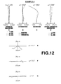
- FIG. 12 Sections A through G illustrate aberration diagrams of the imaging lens in Example 4 of the present invention.
- FIG. 13 Sections A through G illustrate aberration diagrams of the imaging lens in Example 5 of the present invention.
- FIG. 14 Sections A through G illustrate aberration diagrams of the imaging lens in Example 6 of the present invention.
- FIG. 15 Sections A through G illustrate aberration diagrams of the imaging lens in Example 7 of the present invention.
- FIG. 16 Sections A through G illustrate aberration diagrams of the imaging lens in Example 8 of the present invention.
- FIG. 17 is a diagram for explaining arrangement of an imaging apparatus for in-vehicle use according to an embodiment of the present invention.
- FIG. 1 through FIG. 8 are cross sections illustrating structural examples of imaging lenses according to embodiments of the present invention.
- FIG. 1 through FIG. 8 correspond to imaging lenses in Examples 1 through 8, which will be described later, respectively.
- the basic structure is similar to each other in the examples illustrated in FIG. 1 through FIG. 8 , and similar illustration methods are used. Therefore, the imaging lenses according to the first and second embodiments of the present invention will be described mainly with reference to FIG. 1 .
- the imaging lens according to the first embodiment of the present invention is a lens system composed of five lenses, in which first lens L 1 , second lens L 2 , third lens L 3 , fourth lens L 4 and fifth lens L 5 are arranged along optical axis Z in this order from an object side.
- Aperture stop St is arranged between third lens L 3 and fourth lens L 4 . Since aperture stop St is arranged between third lens L 3 and fourth lens L 4 , it is possible reduce the size of the imaging lens in the diameter direction.
- Illustrated aperture stop St does not necessarily represent the size nor the shape of aperture stop St, but represents the position of aperture stop St on the optical axis.
- FIG. 1 illustrates axial rays 2 from an object point at infinity, and off-axial rays 3 at maximum angle of view.
- FIG. 1 a case of applying the imaging lens to an imaging apparatus is taken into consideration, and an imaging device 5 arranged at image plane Sim of the imaging lens is also illustrated.
- the imaging lens When the imaging lens is applied to an imaging apparatus, it is desirable to set a cover glass, and a low-pass filter or an infrared ray cut filter, or the like based on the structure of a camera on which the lens is mounted.
- FIG. 1 illustrates an example in which parallel-flat-plate-shaped optical member PP, which is assumed to be such elements, is arranged between fifth lens L 5 and the imaging device 5 (image plane Sim).
- First lens L 1 is a meniscus lens having negative refractive power, and the object-side surface of which is convex.
- Such structure in which first lens L 1 is a meniscus lens having negative refractive power, and the object-side surface of which is convex, is advantageous to widening an angle of view and correcting distortion.
- First lens L 1 which is arranged on the most object side, is likely be exposed to wind and rain or solvent for cleaning. Therefore, there is a risk that dirt, dust, droplets of water or the like remains on first lens L 1 .
- the convex shape of the object-side surface of first lens L 1 is advantageous to reducing such a risk.
- first lens L 1 is a spherical lens.
- first lens L 1 may be an aspherical lens.
- glass is more desirable than resin, as will be described later. Therefore, when first lens L 1 is a spherical lens, first lens L 1 is producible at lower cost, compared with a case in which first lens L 1 is an aspherical lens.
- At least one of the surfaces of each of second lens L 2 , third lens L 3 , fourth lens L 4 and fifth lens L 5 is aspherical.
- various aberrations such as a spherical aberration, a coma aberration, curvature of field and distortion, while structuring the system using a small number of lenses.
- both surfaces of each of second lens L 2 , third lens L 3 , fourth lens L 4 and fifth lens L 5 are aspherical to more excellently correct aberrations.
- the image-side surface of second lens L 2 has a convex shape facing the image side in the vicinity of the optical axis, and second lens L 2 has negative refractive power.
- point Q 1 and point Q 2 are two effective diameter outermost edge points on the image-side surface of second lens L 2
- point Q 3 is a point on the optical axis on the image-side surface of second lens L 2
- arc C 2 is an arc that passes through the three points of point Q 1 , point Q 2 and point Q 3 . Arc C 2 will be described later.
- a point on the image-side surface of second lens L 2 in the vicinity of point Q 3 is point X 4
- an intersection of a normal at point X 4 and the optical axis is point P 4 .
- the shape of second lens L 2 at point X 4 is defined based on whether point P 4 is located on the object side of point Q 3 or on the image side of point Q 3 .
- the shape of the image-side surface is defined as a convex shape facing the image side when point P 4 is located on the object side of point Q 3 .
- the shape of the image-side surface is defined as a concave shape facing the image side when point P 4 is located on the image side of point Q 3 .
- the image-side surface has a convex shape facing the image side in the vicinity of the optical axis means a shape in which point P 4 is located on the object side of point Q 3 in the vicinity of the optical axis.
- second lens L 2 When the image-side surface of second lens L 2 has a convex shape facing the image side in the vicinity of the optical axis, and second lens L 2 has negative refractive power, it is possible to suppress an angle of incidence of axial rays passing through the image-side surface of second lens L 2 so that the angle is small. Therefore, it is possible to excellently correct a spherical aberration.
- Third lens L 3 , fourth lens L 4 and fifth lens L 5 have positive refractive power, positive refractive power and negative refractive power, respectively.
- the imaging lens according to the first embodiment satisfies the following conditional formula (2-1): 0.11 ⁇ d 1-4 /L (2-1), where
- d 1 - 4 a distance on the optical axis from the object-side surface of first lens L 1 to the image-side surface of second lens L 2 .
- first lens L 1 and second lens L 2 are located close to each other at their peripheral portions, and it becomes impossible to arrange them in an appropriate manner.
- the refractive power and the shape of each of first lens L 1 through fifth lens L 5 are appropriate set, as described above, in a five-group five-element lens structure.
- aperture stop St is arranged between third lens L 3 and fourth lens L 4 . Therefore, a sufficiently wide angle of view and a sufficiently large maximum aperture are achieved while the imaging lens consists of a small number of lenses, and the total length of the imaging lens is short, and the size of the imaging lens is small, and the cost of the imaging lens is low. Further, it is possible to correct various aberrations including a spherical aberration, a coma aberration, curvature of field and distortion in an excellent manner. Further, according to the imaging lens in the first embodiment of the present invention, it is possible to achieve high resolution in a wide range of image formation area. Therefore, it is possible to cope with an imaging device the resolution of which became higher in recent years.
- the imaging lens according to the second embodiment of the present invention is a lens system composed of five lenses, in which first lens L 1 , second lens L 2 , third lens L 3 , fourth lens L 4 and fifth lens L 5 are arranged along optical axis Z in this order from an object side.
- Aperture stop St is arranged between third lens L 3 and fourth lens L 4 . Since aperture stop St is arranged between third lens L 3 and fourth lens L 4 , it is possible reduce the size of the imaging lens in the diameter direction.
- First lens L 1 is a meniscus lens having negative refractive power, and the object-side surface of which is convex.
- Such structure in which first lens L 1 is a meniscus lens having negative refractive power, and the object-side surface of which is convex, is advantageous to widening an angle of view and correcting distortion.
- First lens L 1 which is arranged on the most object side, is likely be exposed to wind and rain or solvent for cleaning. Therefore, there is a risk that dirt, dust, droplets of water or the like remains on first lens L 1 .
- the convex shape of the object-side surface of first lens L 1 is advantageous to reducing such a risk.
- At least one of the surfaces of each of second lens L 2 , third lens L 3 , fourth lens L 4 and fifth lens L 5 is aspherical.
- various aberrations such as a spherical aberration, a coma aberration, curvature of field and distortion, while structuring the system using a small number of lenses.
- both surfaces of each of second lens L 2 , third lens L 3 , fourth lens L 4 and fifth lens L 5 are aspherical to more excellently correct aberrations.
- Second lens L 2 , third lens L 3 , fourth lens L 4 and fifth lens L 5 have negative refractive power, positive refractive power, positive refractive power and negative refractive power, respectively.
- the imaging lens according to the second embodiment satisfies the following conditional formula (2-2): 0.40 ⁇ d 1-4 /L (2-2), where
- d 1 - 4 a distance on the optical axis from the object-side surface of first lens L 1 to the image-side surface of second lens L 2 .
- first lens L 1 and second lens L 2 are located close to each other at their peripheral portions, and it becomes impossible to arrange them in an appropriate manner.
- the refractive power and the shape of each of first lens L 1 through fifth lens L 5 are appropriate set, as described above, in a five-group five-element lens structure.
- aperture stop St is arranged between third lens L 3 and fourth lens L 4 . Therefore, a sufficiently wide angle of view and a sufficiently large maximum aperture are achieved while the imaging lens consists of a small number of lenses, and the total length of the imaging lens is short, and the size of the imaging lens is small, and the cost of the imaging lens is low. Further, it is possible to correct various aberrations including a spherical aberration, a coma aberration, curvature of field and distortion in an excellent manner. Further, according to the imaging lens in the second embodiment of the present invention, it is possible to achieve high resolution in a wide range of image formation area. Therefore, it is possible to cope with an imaging device the resolution of which became higher in recent years.
- the Abbe number of the material of first lens L 1 for d-line is greater than or equal to 40. It is desirable that the Abbe number of the material of second lens L 2 for d-line is greater than or equal to 50. It is desirable that the Abbe number of the material of third lens L 3 for d-line is less than or equal to 30. It is desirable that the Abbe number of the material of fourth lens L 4 for d-line is greater than or equal to 50. It is desirable that the Abbe number of the material of fifth lens L 5 for d-line is less than or equal to 30.
- first lens L 1 , second lens L 2 , third lens L 3 , fourth lens and fifth lens L 5 have negative refractive power, negative refractive power, positive refractive power, positive refractive power and negative refractive power, respectively, in the vicinity of the optical axis, and materials with appropriate Abbe numbers are selected for the lenses, it is possible to excellently correct a lateral chromatic aberration while achieving a wide angle lens exceeding 200 degrees.
- a distance between fourth lens L 4 and fifth lens L 5 is short, and does not substantially change from a central portion through a peripheral portion of the lenses. Further, it is desirable that the thickness of fifth lens L 5 at its central portion and the thickness of fifth lens L 5 at its peripheral portion do not substantially differ from each other. Then, rays pass through the image-side surface of fourth lens L 4 , the object-side surface of fifth lens L 5 and the image-side surface of fifth lens L 5 at substantially the same angle for any angle of view. Therefore, it is possible to prevent sudden generation of aberrations by production error or the like.
- the imaging lens according to the embodiment of the present invention further includes the following structure or structures.
- a desirable mode may include one of the following structures, or arbitrary two or more of them in combination.
- d 4 - 5 a distance on the optical axis from the image-side surface of second lens L 2 to the object-side surface of third lens L 3 , and
- f a focal length of an entire system.
- second lens L 2 and third lens L 3 are too close to each other, and a risk of touching each other increases. Further, it becomes difficult to remove ghost light caused by the two surfaces of the image-side surface of second lens L 2 and the object-side surface of third lens L 3 .
- d 10 the thickness of fifth lens L 5 on the optical axis.
- f 3 a focal length of third lens L 3 .
- conditional formula (10) If the value is lower than the lower limit of conditional formula (10), the image-side surface of fifth lens L 5 and the image plane become too close to each other, and a defect, such as a scratch on a lens, greatly affects an image. Further, it becomes difficult to arrange the lens in an appropriate manner.
- r 10 a curvature radius of an object-side surface of fifth lens L 5 in the vicinity of the optical axis.
- the value exceeds the upper limit of conditional formula (11) If the value exceeds the upper limit of conditional formula (11), the absolute value of the curvature radius of the object-side surface of fifth lens L 5 in the vicinity of the optical axis becomes too small. Therefore, it becomes difficult to excellently correct a spherical aberration.
- the curvature radius of the object-side surface of fifth lens L 5 is set at an appropriate value so that desirable optical performance is achievable, if the value exceeds the upper limit of conditional formula (11), a focal length becomes long. Hence, it becomes impossible to secure a necessary angle of view.
- r 8 a curvature radius of an object-side surface of fourth lens L 4 in the vicinity of the optical axis
- r 9 a curvature radius of an image-side surface of fourth lens L 4 in the vicinity of the optical axis.
- conditional formulas (7-1) through (13-1) are satisfied.
- conditional formulas (7-1) and (13-1) are satisfied, it is possible to achieve effects similar to those achievable by satisfying conditional formulas (7) through 13), or to further enhance the effects: 0.20 ⁇ d 4-5 /f ⁇ 0.60 (7-1); 0.20 ⁇ d 10 /f ⁇ 0.80 (8-1); 2.0 ⁇ f 3 /f ⁇ 20.0 (9-1); 1.5 ⁇ Bf/f ⁇ 3.0 (10-1); ⁇ 5.0 ⁇ r 10 /f ⁇ 0.50 (11-1); 5.0 ⁇ L/f ⁇ 20.0 (12-1); and ( r 8 +r 9)/( r 8 ⁇ r 9) ⁇ 2.0 (13-1).
- conditional formula (7-1) If the value exceeds the upper limit of conditional formula (7-1), the structure is disadvantageous to minimizing the total lens length.
- conditional formula (8-1) If the value exceeds the upper limit of conditional formula (8-1), the structure is disadvantage to reducing the total lens length. Further, it becomes difficult to provide a sufficient back focus.
- conditional formula (10-1) If the value exceeds the upper limit of conditional formula (10-1), it is possible to provide a sufficient distance between fifth lens L 5 and an image plane. However, a distance from the object-side surface of first lens L 1 to the image plane becomes long. Therefore, the size of the imaging lens according to the embodiment of the present invention and the size of an imaging apparatus, such as a camera, to which the imaging lens according to the embodiment of the present invention has been applied become large.
- the size of the imaging lens according to the embodiment of the present invention and the size of an imaging apparatus, such as a camera, to which the imaging lens according to the embodiment of the present invention has been applied become large.
- arcs each of which passes through three points of two effective diameter outermost edge points and a point on an optical axis, are defined for an object-side surface and an image-side surface in a cross section including the optical axis.
- each of the lenses has a whole shape in which the object-side surface and the image-side surface have curvature radii of the arcs, respectively, if the image-side surface of second lens L 2 has a concave shape facing the image side, and second lens L 2 has negative refractive power, and the object-side surface of third lens L 3 has a convex shape facing the object side, and third lens has positive refractive power, and the image-side surface of fourth lens L 4 has a convex shape facing the image side, and fourth lens L 4 has positive refractive power, and fifth lens L 5 has a meniscus shape with its convex surface facing the image side and negative refractive power, it is desirable that the following conditional formulas (1) through (6) are satisfied: 0.10 ⁇ f 34 /L ⁇ 0.17 (1); 0.40 ⁇ d 1-4 /L ⁇ 0.50 (2); 0.45 ⁇ d 3-11 /L ⁇ 0.54 (3); 0.02 ⁇ d 4-5 /L ⁇ 0.05 (4); 0.012
- f 34 a combined paraxial focal length of third lens L 3 and fourth lens L 4 ,
- d 1 - 4 a distance on an optical axis from an object-side surface of first lens L 1 to an image-side surface of second lens L 2 ,
- d 3 - 11 a distance on an optical axis from an object-side surface of second lens L 2 to an image-side surface of fifth lens L 5 ,
- d 4 - 5 a distance on an optical axis from an image-side surface of second lens L 2 to an object-side surface of third lens L 3 ,
- d 6 - 8 a distance on an optical axis from an image-side surface of third lens L 3 to an object-side surface of fourth lens L 4 , and
- r 3 a curvature radius of an object-side surface of second lens L 2 in the vicinity of an optical axis.
- arc C 2 is an arc that passes through three points Q 1 , Q 2 and Q 3 .
- the expression “the image-side surface has a concave shape facing the image side” means that arc C 2 , which passes through the three points of point Q 1 , point Q 2 and point Q 3 , has a concave shape facing the image side when it is assumed that the image-side surface of second lens L 2 has a lens surface defined by arc C 2 .
- the image-side surface of second lens L 2 has a shape in which point Q 3 is located at a more object-side position, compared with point Q 1 and point Q 2 .
- the expression “has negative refractive power” means that the refractive power of a lens having a whole shape assumed with respect to the object side and the image side is negative.
- the shape of the object-side surface of third lens L 3 may be considered in a similar manner to second lens L 2 , which has been described already.
- the expression “the object-side surface has a convex shape facing the object side” means that arc C 3 , which passes through three points of two effective diameter outermost edge points Q 11 and Q 12 on the object-side surface of third lens L 3 and point Q 13 on an optical axis on the object-side surface of third lens L 3 , has a convex shape facing the object side when it is assumed that the object-side surface of third lens L 3 has a lens surface defined by arc C 3 .
- the object-side surface of third lens L 3 has a shape in which point Q 13 is located at a more object-side position, compared with point Q 11 and point Q 12 .
- the expression “has positive refractive power” means that the refractive power of a lens having a whole shape assumed with respect to the object side and the image side is positive.
- the shape of the image-side surface of fourth lens L 4 may be considered in a similar manner to second lens L 2 , which has been described already.
- the expression “the image-side surface has a convex shape facing the image side” means that arc C 4 , which passes through three points of two effective diameter outermost edge points Q 21 and Q 22 on the image-side surface of fourth lens L 4 and point Q 23 on an optical axis on the image-side surface of fourth lens L 4 , has a convex shape facing the image side when it is assumed that the image-side surface of fourth lens L 4 has a lens surface defined by arc C 4 .
- the image-side surface of fourth lens L 4 has a shape in which point Q 23 is located at a more image-side position, compared with point Q 21 and point Q 22 .
- the expression “has positive refractive power” means that the refractive power of a lens having a whole shape assumed with respect to the object side and the image side is positive.
- a meniscus shape with its convex surface facing the image side means a meniscus shape in which arc C 5 , which passes through three points of two effective diameter outermost edge points Q 31 and Q 32 on the image-side surface of fifth lens L 5 and point Q 33 on an optical axis on the image-side surface of fifth lens L 5 , is convex toward the image side when it is assumed that the image-side surface of fifth lens L 5 has a lens surface defined by arc C 5 .
- fifth lens L 5 has a meniscus shape in which point Q 33 is located at a more image-side position, compared with point Q 31 and point Q 32 .
- the expression “has negative refractive power” means that the refractive power of a lens having a whole shape assumed with respect to the object side and the image side is negative.
- the value is lower than the lower limit of conditional formula (1), the absolute value of the refractive power of third lens L 3 and fourth lens L 4 becomes too large, and requirement regarding production error of each lens and accurate registration becomes high. Therefore, the production characteristics become lower, and that causes an increase in cost. If the value exceeds the upper limit of conditional formula (1), the refractive power of the entire lens system becomes insufficient, and a necessary angle of view is not obtainable.
- first lens L 1 and second lens L 2 are located close to each other at their peripheral portions, and it becomes impossible to arrange them in an appropriate manner. If the value exceeds the upper limit of conditional formula (2), the effective diameter of first lens L 1 becomes large, and the total length and the outer diameter of the entire lens system become large.
- the thicknesses of second lens L 2 through fifth lens L 5 and distances between lenses of second lens L 2 through fifth lens L 5 need to be reduced. Therefore, the production characteristics of each lens deteriorate, and it becomes impossible to appropriately set the refractive power of each lens. Further, it becomes difficult to correct chromatic aberrations in an excellent manner. If the value exceeds the upper limit of conditional formula (3), it becomes impossible to achieve reduction in the size of the lens, and the size of the lens becomes large.
- second lens L 2 and third lens L 3 are too close to each other, and a risk of touching each other increases. Further, it becomes difficult to remove ghost light caused by the two surfaces of the image-side surface of second lens L 2 and the object-side surface of third lens L 3 . If the value exceeds the upper limit of conditional formula (4), it becomes difficult to reduce the total length of the lens.
- third lens L 3 and fourth lens L 4 are too close to each other, and it becomes difficult to form aperture stop St between them. If the value exceeds the upper limit of conditional formula (5), it becomes difficult to reduce the total length of the lens.
- conditional formula (6) If the value exceeds the upper limit of conditional formula (6), it becomes difficult to correct a spherical aberration in an excellent manner.
- the thickness of fifth lens L 5 becomes too small, and production becomes difficult. If the value exceeds the upper limit of conditional formula (8-2), the thickness of fifth lens L 5 becomes too large, and the size of a lens becomes large. If a distance from the object-side surface of first lens L 1 to the image plane is tried to be suppressed, it becomes difficult to secure a sufficient back focus.
- conditional formulas (7-3) and (8-3) are satisfied.
- conditional formulas (7-3) and (8-3) it is possible to enhance the effect achievable by satisfying conditional formulas (7-2) and (8-2). 0.15 ⁇ d 4-5 /f ⁇ 0.66 (7-3) 0.46 ⁇ d 10 /f ⁇ 0.54 (8-3)
- second lens L 2 and third lens L 3 are too close to each other, and a risk of touching each other increases. Further, it becomes difficult to remove ghost light caused by the two surfaces of the image-side surface of second lens L 2 and the object-side surface of third lens L 3 .
- conditional formula (10-2) If the value is lower than the lower limit of conditional formula (10-2), the image-side surface of fifth lens L 5 and the image plane become too close to each other, and a defect, such as a scratch on a lens, greatly affects an image. Further, it becomes difficult to arrange the lens in an appropriate manner.
- conditional formulas (9-3) and (10-3) are satisfied.
- conditional formulas (9-3) and (10-3) it is possible to enhance the effect achievable by satisfying conditional formulas (9-2) and (10-2).
- 4.7 ⁇ f 3 /f ⁇ 20.0 (9-3) 1.77 ⁇ Bf/f ⁇ 2.3 (10-3)
- the refractive power of third lens L 3 becomes too weak, and correction of a lateral chromatic aberration becomes insufficient. If the value exceeds the upper limit of conditional formula (10-3), it is possible to make a distance from fifth lens L 5 to the image plane sufficient, but a distance from the object-side surface of first lens L 1 to the image plane becomes long. Therefore, the size of the imaging lens according to the embodiment of the present invention and the size of an imaging apparatus, such as a camera, to which the imaging lens according to the embodiment of the present invention has been applied become large.
- conditional formulas (11-2) and (12-2) are satisfied: ⁇ 1.33 ⁇ r 10 /f ⁇ 0.64 (11-2); and 11.9 ⁇ L/f (12-2).
- the value is lower than the lower limit of conditional formula (11-2), when a focal length required for the angle of view is appropriately set, the curvature radius of the object-side surface of fifth lens L 5 in the vicinity of the optical axis becomes large. Therefore, the effect of correcting a spherical aberration becomes low. If the value exceeds the upper limit of conditional formula (11-2), the absolute value of the curvature radius of the object-side surface of fifth lens L 5 in the vicinity of the optical axis becomes too small. Therefore, it becomes difficult to excellently correct a spherical aberration.
- the size of the imaging lens according to the embodiment of the present invention becomes large. Further, the size of an imaging apparatus, such as a camera, to which the imaging lens according to the embodiment of the present invention has been applied becomes large.
- second lens L 2 When the object-side surface of second lens L 2 has a concave shape facing the object side in the vicinity of the optical axis, and second lens L 2 has negative refractive power, it is desirable that the following conditional formulas (13-2) and (12-4) are satisfied: 0.75 ⁇ ( r 8 +r 9)/( r 8 ⁇ r 9) ⁇ 2.96 (13-2); and 1.6 ⁇ L/f ⁇ 15.7 (12-4).
- the shape of the object-side surface of second lens L 2 may be considered in a similar manner to the shape of the image-side surface of second lens L 2 .
- an intersection of the object-side surface of second lens L 2 and the optical axis is point Q 13
- a point on the object-side surface of second lens L 2 in the vicinity of point Q 13 is point X 3 .
- an intersection of a normal at point X 3 and the optical axis is point P 3 .
- the shape of second lens L 2 at point X 3 is defined based on whether point P 3 is located on the object side of point Q 13 or on the image side of point Q 13 .
- the shape of an object-side surface is defined as a concave shape facing the object side when point P 3 is located on the object side of point Q 13 .
- the shape of the object-side surface is defined as a convex shape facing the object side when point P 3 is located on the image side of point Q 13 .
- the object-side surface has a concave shape facing the object side in the vicinity of the optical axis means a shape in which point P 3 is located on the object side of point Q 13 in the vicinity of the optical axis.
- second lens L 2 When the object-side surface of second lens L 2 has a concave shape facing the object side in the vicinity of the optical axis, and second lens L 2 has negative refractive power, it is possible to suppress an angle of incidence of axial rays passing through the image-side surface of second lens L 2 so that the angle is small. Therefore, it is possible to excellently correct a spherical aberration.
- the value is lower than the lower limit of conditional formula (12-4), when a distance on the optical axis from the object-side surface of first lens L 1 to the image plane is set at an appropriate length, the focal length becomes long. Therefore, it becomes impossible to obtain a large angle of view. If the value exceeds the upper limit of conditional formula (12-4), when a necessary angle of view is secured, a distance from the object-side surface of first lens L 1 to the image plane becomes too long. Therefore, the size of the imaging lens according to the embodiment of the present invention and the size of an imaging apparatus, such as a camera, to which the imaging lens according to the embodiment of the present invention has been applied become large.
- conditional formulas (13-3) and (12-5) When the object-side surface of second lens L 2 has a concave shape facing the object side in the vicinity of the optical axis, and second lens L 2 has negative refractive power, it is more desirable that the following conditional formulas (13-3) and (12-5) are satisfied. When conditional formulas (13-3) and (12-5) are satisfied, it is possible to further enhance the effect achievable by satisfying conditional formulas (13-2) and (12-4). 0.75 ⁇ ( r 8 +r 9)/( r 8 ⁇ r 9) ⁇ 2.0 (13-3) 5.0 ⁇ L/f ⁇ 20.0 (12-5)
- the full angle of view of the imaging lens according to the embodiment of the present invention is greater than 200 degrees.
- the full angle of view is twice an angle formed by a principal ray of off-axial rays 3 at the maximum angle of view and optical axis Z.
- the lens system can cope with a need for a wider angle in recent years.
- each of all of first lens L 1 through fifth lens L 5 is a single lens, which is not a cemented lens, for example, as illustrated in the example of FIG. 1 .
- the imaging lens does not include any cemented lens.
- the imaging lens does not include any cemented lens, it is possible to produce the imaging lens at low cost.
- first lens L 1 which is arranged on the most object side, needs to use a material resistant to a deterioration of a surface by wind and rain and a change in temperature by direct sun light. Further, the material needs to be resistant to chemicals, such as oils and fats and detergents. In other words, the material needs to be highly water-resistant, weather-resistant, acid-resistant, chemical-resistant, and the like. For example, it is desirable to use a material with water durability of 1 by the powder method regulated by Japan Optical Glass Manufacturers' Association. Further, in some cases, first lens L 1 needs to use a material that is hard and not easily breakable. If the material of first lens L 1 is glass, it is possible to satisfy such needs. Alternatively, transparent ceramic may be used as the material of first lens L 1 .
- a protection means may be applied to the object-side surface of first lens L 1 to increase the strength, scratch-resistance, and chemical-resistance of the surface.
- the material of first lens L 1 may be plastic.
- the protection means may be a hard coating or a water-repellent coating.
- plastic is used as the material of second lens L 2 , third lens L 3 , fourth lens L 4 and fifth lens L 5 . In such a case, it is possible to accurately produce an aspherical shape and to reduce the weight and the cost.
- plastic When plastic is used as the material, it is desirable to select a material having low water absorption characteristics to minimize a change in performance by absorption of water. Further, it is desirable that the double refraction characteristics of the material, which cause a drop in resolution, are low. As material satisfying these conditions, it is desirable to select cycloolefin-based plastic for second lens L 2 and fourth lens L 4 , and to select polycarbonate-based plastic or polyester-based plastic for third lens L 3 and fifth lens L 5 .
- nano composite material in which particles smaller than the wavelength of light are mixed into plastic, may be used, as the material.
- an anti-reflection coating may be applied to each lens to reduce ghost light, or the like.
- angles formed by tangent lines on a peripheral portion of the image-side surface of first lens L 1 and an optical axis, angles formed by tangent lines on a peripheral portion of the image-side surface of second lens L 2 and the optical axis, and angles formed by tangent lines on a peripheral portion of the object-side surface of third lens L 3 and the optical axis are small. Therefore, the thickness of the anti-reflection coating in the peripheral portion is less than the thickness of the anti-reflection coating in a central portion.
- the wavelength at which reflectance in the vicinity of the center is the lowest is shorter than 600 nm, a wavelength at which reflectance in the peripheral portion is the lowest becomes too short. Therefore, reflectance on a long wavelength side becomes high. Hence, reddish ghost tends to be generated. If the wavelength at which reflectance in the vicinity of the center is the lowest is longer than 900 nm, a wavelength at which reflectance in the central portion is the lowest becomes too long. Therefore, reflectance on a short wavelength side becomes high. Hence, the tone of an image becomes quite reddish, and bluish ghost tends to be generated.
- rays of light passing through the outside of the effective diameter between lenses may become stray light, and reach the image plane. Further, the stray light may become ghost. Therefore, it is desirable that a light shield means for blocking the stray light is provided, if necessary.
- the light shield means may be provided, for example, by applying an opaque paint to a portion outside the effective diameter on the image side of a lens, or by providing there an opaque plate member.
- an opaque plate member, as a light shield means may be provided in the optical path of rays that will become stray light.
- a filter that cuts ultraviolet light through blue light or an IR (InfraRed) cut filter, which cuts infrared light, may be inserted between the lens system and the imaging device 5 based on the purpose of use of the imaging lens.
- a coating having properties similar to those of the filter may be applied to a lens surface.
- FIG. 1 illustrates a case in which optical member PP, which is assumed to be various filters, is arranged between a lens system and the imaging device 5 .
- the various filters may be arranged between lenses.
- a coating having an action similar to that of the various filters may be applied to a lens surface of one of the lenses included in the imaging lens.
- Imaging lenses of the present invention will be described.
- Lens cross sections of imaging lenses of Example 1 through Example 8 are illustrated in FIG. 1 through FIG. 8 , respectively.
- Table 1 shows lens data and aspherical surface data of the imaging lens of Example 1.
- Tables 2 through 8 show lens data and aspherical surface data of the imaging lenses of Examples 2 through 8, respectively.
- the most object-side surface of composition elements is the first surface, and surface numbers sequentially increase toward the image side.
- the column of ri shows the curvature radius of the i-th surface
- the column of di shows a distance on optical axis Z between the i-th surface and the (i+1)th surface.
- the sign of a curvature radius is positive when a surface is convex toward the object side, and the sign of a curvature radius is negative when a surface is convex toward the image side.
- the most-object side lens is the first lens, and the number j sequentially increases toward the image side.
- the column of ⁇ dj shows the Abbe number of the j-th optical element for d-line (wavelength is 587.6 nm).
- the lens data include aperture stop St.
- the sign “ ⁇ ” is written for a surface corresponding to aperture stop St.
- optical member PP arranged between fifth lens L 5 and image plane Sim is assumed to be a cover glass, a filter or the like.
- optical member PP uses a glass material with a refractive index of 1.52, and the thickness of optical member PP is 0.3 mm.
- the lens data of Table 1 show, as the curvature radius of an aspherical surface, the numerical value of a curvature radius in the vicinity of an optical axis (a paraxial curvature radius).
- the aspherical surface data show the surface numbers of aspherical surfaces and aspherical surface coefficients related to the respective aspherical surfaces.
- “E ⁇ n” (n: integer) means “ ⁇ 10 ⁇ n ”
- “E+n” means “ ⁇ 10 n ”.
- Zd the depth of an aspherical surface (the length of a perpendicular from a point on the aspherical surface at height h to a plane that contacts with the vertex of the aspherical surface and is perpendicular to the optical axis),
- h height (a length from the optical axis to the lens surface),
- first lens L 1 is optical glass, and both surfaces of first lens L 1 are spherical. Therefore, first lens L 1 has excellent weather resistance characteristics, and first lens L 1 is not easily damaged by earth and sand, or the like. Further, it is possible to produce first lens L 1 relatively at low cost.
- cycloolefin-based plastic is selected as the material of second lens L 2 and fourth lens L 4 .
- polycarbonate-based plastic is selected as the material of third lens L 3 and fifth lens L 5 . Accordingly, materials having low water absorption characteristics are selected to minimize a change in performance by absorption of water.
- Table 9 shows various data and values corresponding to conditional formulas (1) through (13) in the imaging lenses of Examples 1 through 8.
- e-line is a reference wavelength
- Table 9 shows values for the reference wavelength.
- f is a focal length of an entire system
- Bf is a distance (corresponding to back focus) on an optical axis from the image-side surface of the most-image-side lens to an image plane
- L is a distance on the optical axis from the object-side surface of first lens L 1 to image plane Sim
- 2 ⁇ is a full angle of view.
- Bf is a distance in air. Specifically, Bf shows a value calculated by using an equivalent length in air, as the thickness of optical member PP. Similarly, a distance in air is used for a back focus portion of L.
- Table 9 shows, all of Examples 1 through 8 satisfy conditional formulas (1) through (13).
- EXAMPLE 1 EXAMPLE 2
- EXAMPLE 3 EXAMPLE 4
- EXAMPLE 5 EXAMPLE 6
- EXAMPLE 7 EXAMPLE 8 Fno. 2.0 2.0 2.0 2.0 2.0 2.0 2.0 2.0 f 0.910 0.899 0.887 0.890 0.863 0.886 0.950 0.969 Bf 1.982 1.987 1.995 1.987 1.991 2.005 2.095 2.145 L 11.960 12.020 12.018 11.787 11.953 11.825 11.689 11.636 2 ⁇ 220.8* 223.8* 224.2* 219.2* 219.0* 217.6* 218.6* 220.4* f 34 /L 0.133 0.129 0.132 0.136 0.138 0.133 0.131 0.130 d 1-4 /L 0.434 0.444 0.444 0.423 0.417 0.419 0.423 0.422 d 3-11 /L 0.490 0.481 0.480 0.500 0.507 0.503 0.490 0.487 d 4-5 /L 0.036
- FIG. 9 Sections A through G illustrate aberration diagrams of the imaging lens of Example 1.
- FIG. 9 Sections A through D illustrate a spherical aberration, astigmatism, distortion (distortion aberration), and a lateral chromatic aberration (a chromatic aberration of magnification), respectively.
- FIG. 9 Sections E through G illustrate lateral aberrations in a tangential direction for each half angle of view.
- Each aberration diagram illustrates aberrations when e-line is a reference wavelength.
- the diagram of a spherical aberration and the diagram of a lateral chromatic aberration illustrate aberrations also for g-line (wavelength is 436 nm) and C-line (wavelength is 656.27 nm).
- Fno. represents F-number
- ⁇ represents a half angle of view.
- Sections A through G illustrate aberration diagrams of a spherical aberration, astigmatism, distortion (a distortion aberration), a lateral chromatic aberration, and lateral aberrations of the imaging lenses of Examples 2 through 8, respectively.
- the aberration diagram of distortion illustrates a shift amount from an ideal image height 2 ⁇ f ⁇ tan( ⁇ /2) by using focal length f of the entire system and half angle ⁇ of view (variable, 0 ⁇ ). Therefore, the value is minus in a peripheral portion.
- the distortion of the imaging lenses in Examples 1 through 8 is large positive values when the distortion is calculated by using, as reference, an image height based on equidistant projection. That is because the imaging lenses of Examples 1 through 8 are designed so that images in peripheral portions are large, compared with a lens designed in such a manner to suppress distortion at an image height based on equidistant projection.
- each of the imaging lenses of Examples 1 through 8 consists of five lenses, which are a small number of lenses, and the size is small, and the cost is low. Further, it is possible to achieve an extremely wide full angle of view of about 220 degrees. Further, F-number is 2.0, which is small. Further, the imaging lens has excellent optical performance in which each aberration has been corrected in an excellent manner and resolution is high. These imaging lenses are appropriate for use in a surveillance camera, an in-vehicle camera for imaging an image on the front side, the lateral sides, the rear side or the like of a car, or the like.
- FIG. 17 illustrates, as an example of usage, a manner of mounting an imaging apparatus including the imaging lens of the embodiment of the present invention in a car 100 .
- the car 100 includes an exterior camera 101 for imaging a driver's blind spot on a side of a seat next to the driver, an exterior camera 102 for imaging a driver's blind spot on a rear side of the car 100 , and an interior camera 103 for imaging the same range as the driver's visual field.
- the interior camera 103 is attached to the back side of a rearview mirror.
- the exterior camera 101 , the exterior camera 102 , and the interior camera 103 are imaging apparatuses according to an embodiment of the present invention, and they include an imaging lens according to an example of the present invention and an imaging device for converting an optical image formed by the imaging lens into electrical signals.
- the imaging lenses according to the examples of the present invention have the aforementioned advantages. Therefore, the exterior cameras 101 and 102 , and the interior camera 103 can be structured in small size and at low cost, and have wide angles of view. Further, they can obtain excellent images with high resolution.
- values of a curvature radius, a distance between surfaces, a refractive index, an Abbe number and aspherical surface coefficients of each lens element are not limited to the values in the aforementioned examples of numerical values, but may be other values.
- the material of the lens is not limited to the material used in each example of numerical values, but may be other materials.
- the present invention is applied to an in-vehicle camera was described with reference to the drawing.
- the use of the present invention is not limited to this purpose.
- the present invention may be applied to a camera for a mobile terminal, a surveillance camera, and the like.
Abstract
Description
0.11<d1-4/L (2-1), where
0.40<d1-4/L (2-2), where
0.10<f34/L<0.17 (1);
0.40<d1-4/L<0.50 (2);
0.45<d3-11/L<0.54 (3);
0.02<d4-5/L<0.05 (4);
0.012<d6-8/L<0.04 (5);
L/r3<−6.0 (6);
0.08<d4-5/f (7);
0.04<d10/f (8);
0.48<f3/f (9);
0.71<Bf/f (10);
r10/f<−0.25 (11);
1.2<L/f (12); and
(r8+r9)/(r8−r9)<2.9 (13), where
0.20<d4-5/f<0.60 (7-1);
0.20<d10/f<0.80 (8-1);
2.0<f3/f<20.0 (9-1);
1.5<Bf/f<3.0 (10-1);
−5.0<r10/f<−0.50 (11-1);
5.0<L/f<20.0 (12-1); and
(r8+r9)/(r8−r9)<2.0 (13-1).
0.11<d1-4/L (2-1), where
0.40<d1-4/L (2-2), where
0.08<d4-5/f (7), where
0.04<d10/f (8), where
0.48<f3/f (9), where
0.71<Bf/f (10), where
r10/f<−0.25 (11), where
1.2<L/f (12).
(r8+r9)/(r8−r9)<2.9 (13), where
0.20<d4-5/f<0.60 (7-1);
0.20<d10/f<0.80 (8-1);
2.0<f3/f<20.0 (9-1);
1.5<Bf/f<3.0 (10-1);
−5.0<r10/f<−0.50 (11-1);
5.0<L/f<20.0 (12-1); and
(r8+r9)/(r8−r9)<2.0 (13-1).
0.10<f34/L<0.17 (1);
0.40<d1-4/L<0.50 (2);
0.45<d3-11/L<0.54 (3);
0.02<d4-5/L<0.05 (4);
0.012<d6-8/L<0.04 (5); and
L/r3<−6.0 (6), where
0.40<d1-4/L<0.60 (2-3).
d4-5/f<1.76 (7-2); and
0.08<d10/f<0.54 (8-2).
0.15<d4-5/f<0.66 (7-3)
0.46<d10/f<0.54 (8-3)
4.7<f3/f (9-2); and
1.84<Bf/f (10-2).
4.7<f3/f<20.0 (9-3)
1.77<Bf/f<2.3 (10-3)
−1.33<r10/f<−0.64 (11-2); and
11.9<L/f (12-2).
11.9<L/f<20.0 (12-3).
0.75<(r8+r9)/(r8−r9)<2.96 (13-2); and
1.6<L/f<15.7 (12-4).
0.75<(r8+r9)/(r8−r9)<2.0 (13-3)
5.0<L/f<20.0 (12-5)
Zd=C·h 2/{1+(1−K·C 2 ·h 2)1/2 }+Σam·h m, where
| TABLE 1 |
| EXAMPLE 1 |
| LENS DATA |
| SURFACE | ri | di | Nej | νdj |
| 1 | 13.985 | 1.373 | 1.77250 | 49.6 |
| 2 | 3.926 | 2.741 | ||
| *3 | −1.141 | 1.079 | 1.53391 | 55.9 |
| *4 | −4.611 | 0.435 | ||
| *5 | 3.518 | 1.907 | 1.61399 | 25.5 |
| *6 | −26.288 | 0.342 | ||
| 7 | ∞ | 0.049 | ||
| *8 | 7.402 | 1.532 | 1.53391 | 55.9 |
| *9 | −0.659 | 0.078 | ||
| *10 | −0.641 | 0.441 | 1.61399 | 25.5 |
| *11 | −1.078 | |||
| ASPHERICAL SURFACE DATA |
| SURFACE NUMBER |
| S3 | S4 | S5 | S6 | |
| K | 0 | 0 | 0 | 0 |
| a3 | 3.576464E−01 | 7.706201E−01 | 3.515082E−01 | −7.947400E−02 |
| a4 | −1.016111E−01 | −6.044794E−01 | −4.246929E−01 | 3.505654E−01 |
| a5 | 8.479838E−03 | 2.856369E−01 | 3.918567E−01 | −3.154111E−01 |
| a6 | −4.623276E−04 | 4.358390E−01 | 7.984634E−02 | −1.394462E−01 |
| a7 | −3.409172E−03 | −9.495146E−02 | −4.286800E−01 | 6.793783E−01 |
| a8 | 1.625375E−03 | −3.510710E−01 | 3.279487E−01 | −4.308856E−01 |
| a9 | 1.534663E−04 | −7.505533E−02 | −1.131106E−01 | −9.795827E−02 |
| a10 | −5.995773E−05 | 9.423859E−02 | 3.871380E−02 | −2.133580E−01 |
| a11 | −1.411097E−05 | 7.736418E−02 | −3.450454E−02 | 3.899051E−01 |
| a12 | −3.829580E−06 | −1.422350E−02 | 1.047480E−02 | 1.022302E+00 |
| a13 | −1.805495E−06 | 1.923155E−02 | −6.770055E−03 | −1.881608E+00 |
| a14 | 1.156699E−06 | −1.060713E−02 | 6.295750E−03 | 8.744934E−01 |
| a15 | −5.925829E−08 | −4.498603E−03 | 4.715367E−03 | −3.435509E−01 |
| a16 | 4.734991E−08 | −8.998241E−03 | 1.533831E−03 | 6.730979E−01 |
| a17 | 4.849819E−09 | 1.707355E−03 | −3.396328E−03 | −1.036047E+00 |
| a18 | −6.436196E−09 | 1.433295E−03 | −2.127777E−04 | 3.160080E−01 |
| a19 | −9.040534E−10 | 2.016128E−03 | −7.678793E−04 | 7.705161E−01 |
| a20 | 3.473144E−10 | −9.504585E−04 | 6.405319E−04 | −4.699698E−01 |
| SURFACE NUMBER |
| S8 | S9 | S10 | S11 | |
| K | 0 | 0 | 0 | 0 |
| a3 | −1.396500E−01 | 7.025409E−02 | 1.078557E−01 | 4.663454E−02 |
| a4 | 1.352860E+00 | −1.527332E−01 | −7.438782E−01 | −7.122033E−01 |
| a5 | −7.713490E+00 | 1.910193E+00 | 2.833043E+00 | 2.475412E+00 |
| a6 | 2.783909E+01 | −4.052031E+00 | −4.603685E+00 | −4.172161E+00 |
| a7 | −6.159921E+01 | 2.020579E+00 | 2.150063E+00 | 2.085344E+00 |
| a8 | 1.205453E+02 | 1.294629E+00 | 9.379704E−01 | 1.113230E+00 |
| a9 | −3.909677E+02 | 1.255004E+00 | 1.346708E+00 | 1.276477E+00 |
| a10 | 7.844087E+02 | −2.094913E+00 | −1.532997E+00 | −1.782637E+00 |
| a11 | 1.161999E+03 | −5.908116E+00 | −6.106926E+00 | −5.795929E+00 |
| a12 | −8.651383E+03 | 8.044380E+00 | 8.112672E+00 | 7.829564E+00 |
| a13 | 1.412214E+04 | −1.729469E+00 | −1.750387E+00 | −1.789756E+00 |
| a14 | −5.230743E+03 | −7.030856E−02 | 1.419159E−01 | −1.259836E−02 |
| a15 | 5.891316E+03 | −6.305335E−01 | −8.208504E−01 | −7.646552E−01 |
| a16 | −3.904402E+04 | 1.108659E−01 | −6.985194E−02 | 6.854295E−02 |
| a17 | 1.845009E+04 | −8.579107E−01 | −5.781271E−01 | −4.924041E−01 |
| a18 | 1.008726E+05 | 1.224937E+00 | 1.032975E+00 | 9.225144E−01 |
| a19 | −1.476223E+05 | −3.756974E−01 | −4.717136E−01 | −3.442198E−01 |
| a20 | 5.987350E+04 | −2.590228E−02 | 9.186641E−02 | 1.025721E−02 |
| TABLE 2 |
| EXAMPLE 2 |
| LENS DATA |
| SURFACE | ri | di | Nej | νdj |
| 1 | 13.797 | 1.373 | 1.77250 | 49.6 |
| 2 | 3.926 | 2.881 | ||
| *3 | −1.170 | 1.079 | 1.53391 | 55.9 |
| *4 | −5.492 | 0.435 | ||
| *5 | 3.631 | 1.932 | 1.61399 | 25.5 |
| *6 | −20.410 | 0.300 | ||
| 7 | ∞ | 0.049 | ||
| *8 | 8.977 | 1.463 | 1.53391 | 55.9 |
| *9 | −0.661 | 0.078 | ||
| *10 | −0.748 | 0.441 | 1.61399 | 25.5 |
| *11 | −1.349 | |||
| ASPHERICAL SURFACE DATA |
| SURFACE NUMBER |
| S3 | S4 | S5 | S6 | |
| K | 0 | 0 | 0 | 0 |
| a3 | 3.539595E−01 | 7.808703E−01 | 3.654480E−01 | −7.591526E−02 |
| a4 | −1.021603E−01 | −5.988237E−01 | −4.428854E−01 | 4.182345E−01 |
| a5 | 8.449642E−03 | 2.696675E−01 | 4.008681E−01 | −4.420593E−01 |
| a6 | −4.445336E−04 | 4.303864E−01 | 8.175390E−02 | −2.159074E−02 |
| a7 | −3.400541E−03 | −8.697305E−02 | −4.260987E−01 | 7.077475E−01 |
| a8 | 1.630302E−03 | −3.514382E−01 | 3.273276E−01 | −4.434090E−01 |
| a9 | 1.548438E−04 | −7.537073E−02 | −1.137188E−01 | −8.739877E−02 |
| a10 | −5.970371E−05 | 9.491822E−02 | 3.862484E−02 | −2.348962E−01 |
| a11 | −1.408423E−05 | 7.665647E−02 | −3.490593E−02 | 3.673860E−01 |
| a12 | −3.899113E−06 | −1.411874E−02 | 1.050747E−02 | 9.820261E−01 |
| a13 | −1.840153E−06 | 1.911943E−02 | −6.664320E−03 | −1.939137E+00 |
| a14 | 1.135292E−06 | −1.050423E−02 | 6.329345E−03 | 1.034345E+00 |
| a15 | −7.052008E−08 | −4.898382E−03 | 4.760936E−03 | −4.396754E−01 |
| a16 | 5.808032E−08 | −8.712266E−03 | 1.546386E−03 | 5.903603E−01 |
| a17 | 4.311106E−09 | 1.688484E−03 | −3.390084E−03 | −1.058621E+00 |
| a18 | −6.579684E−09 | 1.439408E−03 | −2.093136E−04 | 4.583074E−01 |
| a19 | −9.301822E−10 | 2.011399E−03 | −7.712580E−04 | 8.622714E−01 |
| a20 | 3.443170E−10 | −9.533207E−04 | 6.331388E−04 | −5.745744E−01 |
| SURFACE NUMBER |
| S8 | S9 | S10 | S11 | |
| K | 0 | 0 | 0 | 0 |
| a3 | −1.455975E−01 | 5.034487E−02 | 9.931259E−02 | 4.663454E−02 |
| a4 | 1.401127E+00 | −7.834891E−02 | −6.751775E−01 | −6.880257E−01 |
| a5 | −7.739998E+00 | 1.886268E+00 | 2.886397E+00 | 2.455138E+00 |
| a6 | 2.767881E+01 | −3.992784E+00 | −4.562947E+00 | −4.160256E+00 |
| a7 | −6.141640E+01 | 1.887307E+00 | 2.101811E+00 | 2.136864E+00 |
| a8 | 1.204464E+02 | 1.077434E+00 | 7.686593E−01 | 1.074442E+00 |
| a9 | −3.917929E+02 | 1.673703E+00 | 1.012838E+00 | 1.267042E+00 |
| a10 | 7.857260E+02 | −2.156610E+00 | −9.260374E−01 | −1.786298E+00 |
| a11 | 1.163933E+03 | −5.726527E+00 | −5.980687E+00 | −5.796457E+00 |
| a12 | −8.649674E+03 | 7.945970E+00 | 8.013340E+00 | 7.825704E+00 |
| a13 | 1.410989E+04 | −2.139901E+00 | −1.880021E+00 | −1.792560E+00 |
| a14 | −5.242394E+03 | −9.506382E−02 | −1.218706E−02 | −7.919194E−03 |
| a15 | 5.944578E+03 | −1.259505E−01 | −7.611840E−01 | −7.641308E−01 |
| a16 | −3.908654E+04 | 1.329437E−01 | −8.087464E−02 | 8.185696E−02 |
| a17 | 1.837677E+04 | −1.169882E+00 | −6.050233E−01 | −4.754929E−01 |
| a18 | 1.012467E+05 | 1.271018E+00 | 1.071267E+00 | 8.913210E−01 |
| a19 | −1.481055E+05 | −3.571733E−01 | −3.787190E−01 | −3.411988E−01 |
| a20 | 6.005159E+04 | −9.483955E−03 | 3.026210E−02 | 1.415507E−02 |
| TABLE 3 |
| EXAMPLE 3 |
| LENS DATA |
| SURFACE | ri | di | Nej | νdj |
| 1 | 13.751 | 1.373 | 1.77250 | 49.6 |
| 2 | 3.926 | 2.881 | ||
| *3 | −1.193 | 1.079 | 1.53391 | 55.9 |
| *4 | −6.700 | 0.435 | ||
| *5 | 3.373 | 1.952 | 1.61399 | 25.5 |
| *6 | −26.519 | 0.300 | ||
| 7 | ∞ | 0.049 | ||
| *8 | 9.686 | 1.434 | 1.53391 | 55.9 |
| *9 | −0.665 | 0.078 | ||
| *10 | −0.736 | 0.441 | 1.61399 | 25.5 |
| *11 | −1.271 | |||
| ASPHERICAL SURFACE DATA |
| SURFACE NUMBER |
| S3 | S4 | S5 | S6 | |
| K | 0 | 0 | 0 | 0 |
| a3 | 3.528750E−01 | 7.858190E−01 | 3.624675E−01 | −7.577756E−02 |
| a4 | −1.027724E−01 | −5.977613E−01 | −4.462824E−01 | 4.075845E−01 |
| a5 | 8.525890E−03 | 2.644539E−01 | 4.044869E−01 | −4.194860E−01 |
| a6 | −4.291818E−04 | 4.285901E−01 | 8.187106E−02 | −3.787963E−02 |
| a7 | −3.400936E−03 | −8.755624E−02 | −4.255482E−01 | 6.991522E−01 |
| a8 | 1.629023E−03 | −3.518754E−01 | 3.264400E−01 | −4.382556E−01 |
| a9 | 1.543706E−04 | −7.407803E−02 | −1.138905E−01 | −6.431617E−02 |
| a10 | −5.975998E−05 | 9.448077E−02 | 3.792990E−02 | −2.200397E−01 |
| a11 | −1.407886E−05 | 7.671916E−02 | −3.467486E−02 | 3.757396E−01 |
| a12 | −3.866936E−06 | −1.406532E−02 | 1.060082E−02 | 9.848795E−01 |
| a13 | −1.835094E−06 | 1.902902E−02 | −6.623064E−03 | −1.963793E+00 |
| a14 | 1.131884E−06 | −1.043651E−02 | 6.322980E−03 | 1.010611E+00 |
| a15 | −6.939696E−08 | −4.890632E−03 | 4.793065E−03 | −4.590771E−01 |
| a16 | 5.808784E−08 | −8.696599E−03 | 1.562045E−03 | 5.269904E−01 |
| a17 | 4.279327E−09 | 1.672175E−03 | −3.363745E−03 | −1.114633E+00 |
| a18 | −6.605801E−09 | 1.439893E−03 | −2.253217E−04 | 3.013455E−01 |
| a19 | −9.244114E−10 | 2.015326E−03 | −7.604448E−04 | 1.500243E+00 |
| a20 | 3.436345E−10 | −9.555031E−04 | 6.223962E−04 | −9.165478E−01 |
| SURFACE NUMBER |
| S8 | S9 | S10 | S11 | |
| K | 0 | 0 | 0 | 0 |
| a3 | −1.519224E−01 | 3.387135E−02 | 8.350297E−02 | 4.663454E−02 |
| a4 | 1.415819E+00 | −5.282771E−02 | −6.337962E−01 | −6.769970E−01 |
| a5 | −7.739690E+00 | 1.909825E+00 | 2.902839E+00 | 2.445728E+00 |
| a6 | 2.767716E+01 | −4.023987E+00 | −4.563562E+00 | −4.164501E+00 |
| a7 | −6.157586E+01 | 1.880916E+00 | 2.089935E+00 | 2.189921E+00 |
| a8 | 1.203542E+02 | 1.080773E+00 | 7.648836E−01 | 1.028038E+00 |
| a9 | −3.919358E+02 | 1.690765E+00 | 9.986478E−01 | 1.270538E+00 |
| a10 | 7.865038E+02 | −2.159752E+00 | −9.238030E−01 | −1.789935E+00 |
| a11 | 1.164389E+03 | −5.737750E+00 | −5.998119E+00 | −5.796278E+00 |
| a12 | −8.645452E+03 | 7.939014E+00 | 8.026614E+00 | 7.825187E+00 |
| a13 | 1.410403E+04 | −2.149209E+00 | −1.893462E+00 | −1.792557E+00 |
| a14 | −5.240310E+03 | −9.249844E−02 | −1.817119E−02 | −5.863436E−03 |
| a15 | 5.941697E+03 | −1.144137E−01 | −7.704640E−01 | −7.573736E−01 |
| a16 | −3.909321E+04 | 9.036724E−02 | −5.816305E−02 | 8.208472E−02 |
| a17 | 1.836772E+04 | −1.148644E+00 | −6.025709E−01 | −4.762212E−01 |
| a18 | 1.012382E+05 | 1.281340E+00 | 1.075507E+00 | 8.865069E−01 |
| a19 | −1.481062E+05 | −3.542013E−01 | −3.701229E−01 | −3.421460E−01 |
| a20 | 6.010184E+04 | −1.377516E−02 | 1.927957E−02 | 1.626847E−02 |
| TABLE 4 |
| EXAMPLE 4 |
| LENS DATA |
| SURFACE | ri | di | Nej | νdj |
| 1 | 13.820 | 1.373 | 1.77250 | 49.6 |
| 2 | 3.926 | 2.532 | ||
| *3 | −1.203 | 1.079 | 1.53391 | 55.9 |
| *4 | −5.840 | 0.435 | ||
| *5 | 3.610 | 2.004 | 1.61399 | 25.5 |
| *6 | −549.752 | 0.246 | ||
| 7 | ∞ | 0.049 | ||
| *8 | 8.749 | 1.559 | 1.53391 | 55.9 |
| *9 | −0.685 | 0.080 | ||
| *10 | −0.767 | 0.441 | 1.61399 | 25.5 |
| *11 | −1.240 | |||
| ASPHERICAL SURFACE DATA |
| SURFACE NUMBER |
| S3 | S4 | S5 | S6 | |
| K | 0 | 0 | 0 | 0 |
| a3 | 3.528239E−01 | 7.871707E−01 | 3.709377E−01 | −6.747215E−02 |
| a4 | −1.027089E−01 | −5.866915E−01 | −4.476078E−01 | 4.248430E−01 |
| a5 | 8.443777E−03 | 2.548925E−01 | 4.058227E−01 | −4.089012E−01 |
| a6 | −4.443869E−04 | 4.285302E−01 | 7.981317E−02 | −3.170450E−02 |
| a7 | −3.405141E−03 | −8.673852E−02 | −4.209582E−01 | 7.159112E−01 |
| a8 | 1.629517E−03 | −3.505121E−01 | 3.246846E−01 | −4.241142E−01 |
| a9 | 1.572621E−04 | −7.434330E−02 | −1.139138E−01 | −1.038036E−02 |
| a10 | −5.995026E−05 | 9.432114E−02 | 3.763748E−02 | −1.645824E−01 |
| a11 | −1.407746E−05 | 7.668187E−02 | −3.477317E−02 | 2.609583E−01 |
| a12 | −3.858858E−06 | −1.385195E−02 | 1.099434E−02 | 9.574234E−01 |
| a13 | −1.839226E−06 | 1.898585E−02 | −6.515933E−03 | −2.013487E+00 |
| a14 | 1.128370E−06 | −1.044912E−02 | 6.260058E−03 | 9.565004E−01 |
| a15 | −7.074088E−08 | −4.906149E−03 | 4.735694E−03 | −4.454686E−01 |
| a16 | 5.737447E−08 | −8.712883E−03 | 1.551375E−03 | 5.201021E−01 |
| a17 | 4.316429E−09 | 1.711487E−03 | −3.379790E−03 | −1.077566E+00 |
| a18 | −6.365026E−09 | 1.412073E−03 | −2.027941E−04 | 3.101408E−01 |
| a19 | −9.592938E−10 | 2.011982E−03 | −7.575931E−04 | 1.485990E+00 |
| a20 | 3.399841E−10 | −9.504919E−04 | 6.210215E−04 | −9.317541E−01 |
| SURFACE NUMBER |
| S8 | S9 | S10 | S11 | |
| K | 0 | 0 | 0 | 0 |
| a3 | −1.451242E−01 | 4.567079E−02 | 1.030004E−01 | 4.663454E−02 |
| a4 | 1.380315E+00 | −3.232278E−02 | −6.241143E−01 | −6.798062E−01 |
| a5 | −7.587330E+00 | 1.966645E+00 | 2.878062E+00 | 2.434198E+00 |
| a6 | 2.788068E+01 | −4.142655E+00 | −4.582913E+00 | −4.169406E+00 |
| a7 | −6.145819E+01 | 1.901703E+00 | 2.089935E+00 | 2.188735E+00 |
| a8 | 1.185564E+02 | 1.080371E+00 | 7.301002E−01 | 1.036921E+00 |
| a9 | −3.917860E+02 | 1.740564E+00 | 9.836524E−01 | 1.259764E+00 |
| a10 | 7.887811E+02 | −2.164846E+00 | −9.961103E−01 | −1.806298E+00 |
| a11 | 1.160670E+03 | −5.695600E+00 | −5.930647E+00 | −5.804193E+00 |
| a12 | −8.637423E+03 | 7.967917E+00 | 8.021326E+00 | 7.832240E+00 |
| a13 | 1.411073E+04 | −2.214012E+00 | −1.879911E+00 | −1.791759E+00 |
| a14 | −5.261047E+03 | −1.647241E−01 | −1.543738E−02 | −1.107038E−03 |
| a15 | 6.000001E+03 | −2.072213E−01 | −8.197889E−01 | −7.514075E−01 |
| a16 | −3.918723E+04 | 2.979513E−01 | −4.723724E−02 | 8.973097E−02 |
| a17 | 1.837965E+04 | −1.251498E+00 | −5.454829E−01 | −4.832081E−01 |
| a18 | 1.012366E+05 | 1.311809E+00 | 1.068657E+00 | 8.830409E−01 |
| a19 | −1.481151E+05 | −3.247293E−01 | −3.638416E−01 | −3.436322E−01 |
| a20 | 6.016779E+04 | −3.928186E−02 | 1.291888E−03 | 1.853297E−02 |
| TABLE 5 |
| EXAMPLE 5 |
| LENS DATA |
| SURFACE | ri | di | Nej | νdj |
| 1 | 14.044 | 1.373 | 1.77250 | 49.6 |
| 2 | 4.000 | 2.531 | ||
| *3 | −1.262 | 1.079 | 1.53391 | 55.9 |
| *4 | −5.428 | 0.435 | ||
| *5 | 4.799 | 2.051 | 1.61399 | 25.5 |
| *6 | 405.687 | 0.290 | ||
| 7 | ∞ | 0.049 | ||
| *8 | 6.867 | 1.631 | 1.53391 | 55.9 |
| *9 | −0.762 | 0.080 | ||
| *10 | −0.887 | 0.441 | 1.61399 | 25.5 |
| *11 | −1.279 | |||
| ASPHERICAL SURFACE DATA |
| SURFACE NUMBER |
| S3 | S4 | S5 | S6 | |
| K | 0 | 0 | 0 | 0 |
| a3 | 3.517460E−01 | 7.998652E−01 | 3.752971E−01 | −6.554253E−02 |
| a4 | −1.043551E−01 | −5.747079E−01 | −4.221723E−01 | 3.762600E−01 |
| a5 | 8.075871E−03 | 2.505510E−01 | 3.933647E−01 | −4.031976E−01 |
| a6 | −3.246340E−04 | 4.316264E−01 | 7.343820E−02 | 3.447437E−03 |
| a7 | −3.391957E−03 | −8.629798E−02 | −4.226439E−01 | 7.732548E−01 |
| a8 | 1.636731E−03 | −3.534020E−01 | 3.288067E−01 | −5.754362E−01 |
| a9 | 1.566353E−04 | −7.423862E−02 | −1.113689E−01 | −6.684742E−02 |
| a10 | −6.025618E−05 | 9.502495E−02 | 3.835654E−02 | −2.103687E−01 |
| a11 | −1.393241E−05 | 7.670111E−02 | −3.581056E−02 | 1.981708E−01 |
| a12 | −3.946482E−06 | −1.372719E−02 | 1.060292E−02 | 8.791662E−01 |
| a13 | −1.803564E−06 | 1.917962E−02 | −6.622284E−03 | −1.577738E+00 |
| a14 | 1.119655E−06 | −1.044754E−02 | 6.143874E−03 | 8.027891E−01 |
| a15 | −6.934616E−08 | −4.831869E−03 | 4.714941E−03 | −3.173624E−01 |
| a16 | 5.712386E−08 | −8.745329E−03 | 1.527680E−03 | 7.169571E−01 |
| a17 | 4.175144E−09 | 1.630074E−03 | −3.388350E−03 | −1.069141E+00 |
| a18 | −6.417671E−09 | 1.379726E−03 | −1.806104E−04 | 2.621830E−01 |
| a19 | −9.133102E−10 | 2.021259E−03 | −6.985975E−04 | 1.184311E+00 |
| a20 | 3.339660E−10 | −9.379156E−04 | 5.920708E−04 | −7.895090E−01 |
| SURFACE NUMBER |
| S8 | S9 | S10 | S11 | |
| K | 0 | 0 | 0 | 0 |
| a3 | −1.569576E−01 | −5.785700E−02 | 2.199658E−02 | 4.663454E−02 |
| a4 | 1.445080E+00 | 7.307219E−02 | −5.522280E−01 | −6.283695E−01 |
| a5 | −7.973389E+00 | 1.938968E+00 | 2.890316E+00 | 2.370031E+00 |
| a6 | 2.822992E+01 | −4.242168E+00 | −4.650883E+00 | −4.179706E+00 |
| a7 | −6.078376E+01 | 1.885186E+00 | 1.986147E+00 | 2.223874E+00 |
| a8 | 1.189684E+02 | 1.099570E+00 | 7.016923E−01 | 1.051424E+00 |
| a9 | −3.967461E+02 | 1.789500E+00 | 1.174900E+00 | 1.271725E+00 |
| a10 | 7.884569E+02 | −2.135554E+00 | −1.028083E+00 | −1.825452E+00 |
| a11 | 1.169903E+03 | −5.663039E+00 | −5.814384E+00 | −5.829268E+00 |
| a12 | −8.621938E+03 | 8.123190E+00 | 8.030797E+00 | 7.821014E+00 |
| a13 | 1.405177E+04 | −2.312655E+00 | −1.868411E+00 | −1.794051E+00 |
| a14 | −5.228863E+03 | −2.235316E−01 | −1.698062E−01 | 4.448708E−03 |
| a15 | 6.095878E+03 | −2.785967E−01 | −8.828839E−01 | −7.104149E−01 |
| a16 | −3.928297E+04 | 2.686292E−01 | −7.518570E−02 | 8.802676E−02 |
| a17 | 1.828881E+04 | −1.281496E+00 | −5.265268E−01 | −4.916333E−01 |
| a18 | 1.014150E+05 | 1.424467E+00 | 1.128666E+00 | 8.717200E−01 |
| a19 | −1.483395E+05 | −2.884570E−01 | −2.628355E−01 | −3.514156E−01 |
| a20 | 6.032913E+04 | −8.769461E−02 | −7.904207E−02 | 2.708975E−02 |
| TABLE 6 |
| EXAMPLE 6 |
| LENS DATA |
| SURFACE | ri | di | Nej | νdj |
| 1 | 14.408 | 1.400 | 1.77250 | 49.6 |
| 2 | 4.000 | 2.475 | ||
| *3 | −1.278 | 1.079 | 1.53391 | 55.9 |
| *4 | −4.751 | 0.435 | ||
| *5 | 5.334 | 1.916 | 1.63350 | 23.6 |
| *6 | 45.812 | 0.356 | ||
| 7 | ∞ | 0.049 | ||
| *8 | 6.161 | 1.589 | 1.53391 | 55.9 |
| *9 | −0.740 | 0.080 | ||
| *10 | −0.900 | 0.441 | 1.63350 | 23.6 |
| *11 | −1.361 | |||
| ASPHERICAL SURFACE DATA |
| SURFACE NUMBER |
| S3 | S4 | S5 | S6 | |
| K | 0 | 0 | 0 | 0 |
| a3 | 3.524498E−01 | 7.989919E−01 | 3.651150E−01 | −4.655623E−02 |
| a4 | −1.044993E−01 | −5.663033E−01 | −4.130300E−01 | 3.429548E−01 |
| a5 | 8.048027E−03 | 2.382772E−01 | 3.849733E−01 | −4.530138E−01 |
| a6 | −3.174982E−04 | 4.323168E−01 | 7.163680E−02 | 3.098542E−02 |
| a7 | −3.391149E−03 | −8.412983E−02 | −4.238448E−01 | 8.003525E−01 |
| a8 | 1.635585E−03 | −3.533945E−01 | 3.310835E−01 | −5.792977E−01 |
| a9 | 1.552534E−04 | −7.439558E−02 | −1.108394E−01 | −6.312032E−02 |
| a10 | −6.014004E−05 | 9.539393E−02 | 3.830496E−02 | −2.349675E−01 |
| a11 | −1.387944E−05 | 7.700832E−02 | −3.550636E−02 | 1.912835E−01 |
| a12 | −4.003721E−06 | −1.350166E−02 | 1.008123E−02 | 9.258604E−01 |
| a13 | −1.737582E−06 | 1.908142E−02 | −6.452826E−03 | −1.532484E+00 |
| a14 | 1.118464E−06 | −1.050076E−02 | 6.189673E−03 | 9.534326E−01 |
| a15 | −7.032009E−08 | −4.835253E−03 | 4.621763E−03 | −5.898509E−01 |
| a16 | 5.981000E−08 | −8.781092E−03 | 1.551225E−03 | 6.925632E−01 |
| a17 | 1.546138E−09 | 1.622368E−03 | −3.391123E−03 | −1.022029E+00 |
| a18 | −6.107714E−09 | 1.372453E−03 | −1.935510E−04 | 2.165629E−01 |
| a19 | −8.779158E−10 | 2.029179E−03 | −6.763937E−04 | 1.206105E+00 |
| a20 | 3.396878E−10 | −9.366952E−04 | 5.831153E−04 | −7.387666E−01 |
| SURFACE NUMBER |
| S8 | S9 | S10 | S11 | |
| K | 0 | 0 | 0 | 0 |
| a3 | −1.623173E−01 | −9.111810E−02 | −4.879146E−03 | 4.663454E−02 |
| a4 | 1.512853E+00 | 7.762031E−02 | −5.097085E−01 | −6.308846E−01 |
| a5 | −8.157718E+00 | 1.976173E+00 | 2.813067E+00 | 2.349505E+00 |
| a6 | 2.806116E+01 | −4.237071E+00 | −4.679813E+00 | −4.187304E+00 |
| a7 | −6.061270E+01 | 1.846252E+00 | 1.983409E+00 | 2.228751E+00 |
| a8 | 1.196912E+02 | 1.131017E+00 | 7.826555E−01 | 1.040340E+00 |
| a9 | −4.003859E+02 | 1.722891E+00 | 1.218952E+00 | 1.295411E+00 |
| a10 | 7.954933E+02 | −2.135716E+00 | −1.020532E+00 | −1.816854E+00 |
| a11 | 1.175057E+03 | −5.591724E+00 | −5.820776E+00 | −5.828777E+00 |
| a12 | −8.629280E+03 | 8.177616E+00 | 8.005213E+00 | 7.809661E+00 |
| a13 | 1.404758E+04 | −2.360695E+00 | −1.893193E+00 | −1.798908E+00 |
| a14 | −5.284112E+03 | −2.254872E−01 | −1.963544E−01 | 1.920924E−03 |
| a15 | 6.189004E+03 | −3.138562E−01 | −8.770561E−01 | −7.094354E−01 |
| a16 | −3.938952E+04 | 2.629516E−01 | −7.417069E−02 | 9.144957E−02 |
| a17 | 1.832155E+04 | −1.269368E+00 | −5.162215E−01 | −4.901532E−01 |
| a18 | 1.017780E+05 | 1.417278E+00 | 1.142494E+00 | 8.734231E−01 |
| a19 | −1.487501E+05 | −2.698764E−01 | −2.575360E−01 | −3.563668E−01 |
| a20 | 6.038908E+04 | −9.408334E−02 | −8.922199E−02 | 2.907484E−02 |
| TABLE 7 |
| EXAMPLE 7 |
| LENS DATA |
| SURFACE | ri | di | Nej | νdj |
| 1 | 14.193 | 1.400 | 1.77250 | 49.6 |
| 2 | 4.000 | 2.464 | ||
| *3 | −1.263 | 1.079 | 1.53391 | 55.9 |
| *4 | −4.310 | 0.435 | ||
| *5 | 5.482 | 1.826 | 1.63350 | 23.6 |
| *6 | −34.903 | 0.338 | ||
| 7 | ∞ | 0.049 | ||
| *8 | 13.493 | 1.482 | 1.53391 | 55.9 |
| *9 | −0.727 | 0.080 | ||
| *10 | −0.946 | 0.441 | 1.63350 | 23.6 |
| *11 | −1.541 | |||
| ASPHERICAL SURFACE DATA |
| SURFACE NUMBER |
| S3 | S4 | S5 | S6 | |
| K | 0 | 0 | 0 | 0 |
| a3 | 3.536316E−01 | 7.880292E−01 | 3.636482E−01 | −5.450196E−02 |
| a4 | −1.043745E−01 | −5.517757E−01 | −4.138785E−01 | 3.517165E−01 |
| a5 | 8.086207E−03 | 2.398230E−01 | 3.818633E−01 | −4.796000E−01 |
| a6 | −2.994103E−04 | 4.323625E−01 | 7.144213E−02 | 3.960320E−02 |
| a7 | −3.388562E−03 | −8.420763E−02 | −4.238731E−01 | 8.223170E−01 |
| a8 | 1.634511E−03 | −3.546101E−01 | 3.312432E−01 | −6.193223E−01 |
| a9 | 1.556796E−04 | −7.463500E−02 | −1.106446E−01 | −1.075655E−01 |
| a10 | −6.044533E−05 | 9.537100E−02 | 3.828044E−02 | −2.890252E−01 |
| a11 | −1.396756E−05 | 7.702696E−02 | −3.584384E−02 | 2.628614E−01 |
| a12 | −4.027163E−06 | −1.354858E−02 | 1.000754E−02 | 1.006265E+00 |
| a13 | −1.754572E−06 | 1.908346E−02 | −6.363856E−03 | −1.490531E+00 |
| a14 | 1.128860E−06 | −1.051568E−02 | 6.127168E−03 | 9.900953E−01 |
| a15 | −6.998458E−08 | −4.830924E−03 | 4.606509E−03 | −5.221199E−01 |
| a16 | 6.003370E−08 | −8.793153E−03 | 1.539101E−03 | 6.256196E−01 |
| a17 | 1.538872E−09 | 1.612821E−03 | −3.392311E−03 | −1.123885E+00 |
| a18 | −6.176671E−09 | 1.373416E−03 | −1.903847E−04 | 7.472199E−02 |
| a19 | −8.764735E−10 | 2.031628E−03 | −6.727749E−04 | 1.187511E+00 |
| a20 | 3.414674E−10 | −9.350254E−04 | 5.836051E−04 | −6.048059E−01 |
| SURFACE NUMBER |
| S8 | S9 | S10 | S11 | |
| K | 0 | 0 | 0 | 0 |
| a3 | −1.986025E−01 | −1.132695E−01 | −3.514693E−02 | 4.663454E−02 |
| a4 | 1.641797E+00 | 5.135863E−02 | −4.792778E−01 | −6.440957E−01 |
| a5 | −8.266542E+00 | 2.054769E+00 | 2.763917E+00 | 2.319567E+00 |
| a6 | 2.777359E+01 | −4.239523E+00 | −4.751269E+00 | −4.192740E+00 |
| a7 | −6.062212E+01 | 1.768389E+00 | 2.019805E+00 | 2.238442E+00 |
| a8 | 1.205466E+02 | 1.066157E+00 | 7.727097E−01 | 1.040022E+00 |
| a9 | −4.016043E+02 | 1.730008E+00 | 1.243217E+00 | 1.301277E+00 |
| a10 | 7.982730E+02 | −2.107178E+00 | −9.996106E−01 | −1.811002E+00 |
| a11 | 1.177784E+03 | −5.518539E+00 | −5.804124E+00 | −5.828996E+00 |
| a12 | −8.627874E+03 | 8.331675E+00 | 8.051564E+00 | 7.806956E+00 |
| a13 | 1.401829E+04 | −2.436742E+00 | −1.893387E+00 | −1.810157E+00 |
| a14 | −5.285169E+03 | −2.776904E−01 | −2.602873E−01 | 3.764943E−03 |
| a15 | 6.222585E+03 | −4.294121E−01 | −8.897787E−01 | −7.062445E−01 |
| a16 | −3.942633E+04 | 2.175910E−01 | −6.209887E−02 | 9.343433E−02 |
| a17 | 1.833709E+04 | −1.225244E+00 | −5.158942E−01 | −4.893234E−01 |
| a18 | 1.019349E+05 | 1.504704E+00 | 1.147729E+00 | 8.732742E−01 |
| a19 | −1.488307E+05 | −2.400129E−01 | −2.469541E−01 | −3.584106E−01 |
| a20 | 6.029847E+04 | −1.425801E−01 | −9.647233E−02 | 2.993228E−02 |
| TABLE 8 |
| EXAMPLE 8 |
| LENS DATA |
| SURFACE | ri | di | Nej | νdj |
| 1 | 13.743 | 1.400 | 1.77250 | 49.6 |
| 2 | 4.000 | 2.429 | ||
| *3 | −1.287 | 1.079 | 1.53391 | 55.9 |
| *4 | −4.814 | 0.435 | ||
| *5 | 5.404 | 1.838 | 1.63350 | 23.6 |
| *6 | −26.456 | 0.284 | ||
| 7 | ∞ | 0.049 | ||
| *8 | 22.755 | 1.455 | 1.53391 | 55.9 |
| *9 | −0.715 | 0.080 | ||
| *10 | −0.940 | 0.441 | 1.63350 | 23.6 |
| *11 | −1.566 | |||
| ASPHERICAL SURFACE DATA |
| SURFACE NUMBER |
| S3 | S4 | S5 | S6 | |
| K | 0 | 0 | 0 | 0 |
| a3 | 3.506778E−01 | 7.772335E−01 | 3.582847E−01 | −4.414017E−02 |
| a4 | −1.042539E−01 | −5.575118E−01 | −4.154740E−01 | 3.508350E−01 |
| a5 | 8.140741E−03 | 2.409301E−01 | 3.818183E−01 | −4.688635E−01 |
| a6 | −2.844764E−04 | 4.322594E−01 | 7.063641E−02 | 4.316327E−02 |
| a7 | −3.385726E−03 | −8.380970E−02 | −4.236176E−01 | 8.090826E−01 |
| a8 | 1.634681E−03 | −3.554378E−01 | 3.307002E−01 | −6.351442E−01 |
| a9 | 1.556112E−04 | −7.448361E−02 | −1.107577E−01 | −1.171813E−01 |
| a10 | −6.041497E−05 | 9.545300E−02 | 3.831190E−02 | −3.012934E−01 |
| a11 | −1.400335E−05 | 7.711454E−02 | −3.607236E−02 | 2.433253E−01 |
| a12 | −4.049491E−06 | −1.361338E−02 | 1.008879E−02 | 1.019471E+00 |
| a13 | −1.751262E−06 | 1.908552E−02 | −6.373578E−03 | −1.474077E+00 |
| a14 | 1.124692E−06 | −1.052616E−02 | 6.130714E−03 | 1.003956E+00 |
| a15 | −6.941398E−08 | −4.828610E−03 | 4.616366E−03 | −5.076498E−01 |
| a16 | 6.024756E−08 | −8.792558E−03 | 1.541588E−03 | 6.215624E−01 |
| a17 | 1.628210E−09 | 1.610212E−03 | −3.389529E−03 | −1.111912E+00 |
| a18 | −6.154272E−09 | 1.372216E−03 | −1.916274E−04 | 6.300090E−02 |
| a19 | −8.811687E−10 | 2.031670E−03 | −6.737538E−04 | 1.163022E+00 |
| a20 | 3.367721E−10 | −9.343571E−04 | 5.821869E−04 | −5.894363E−01 |
| SURFACE NUMBER |
| S8 | S9 | S10 | S11 | |
| K | 0 | 0 | 0 | 0 |
| a3 | −1.888038E−01 | −1.127371E−01 | −2.847947E−02 | 4.663454E−02 |
| a4 | 1.630949E+00 | 7.311934E−02 | −4.164898E−01 | −6.237245E−01 |
| a5 | −8.260487E+00 | 2.059160E+00 | 2.769265E+00 | 2.307714E+00 |
| a6 | 2.784732E+01 | −4.245308E+00 | −4.770518E+00 | −4.225150E+00 |
| a7 | −6.111454E+01 | 1.713799E+00 | 1.837298E+00 | 2.246912E+00 |
| a8 | 1.208860E+02 | 1.007759E+00 | 7.590351E−01 | 1.044298E+00 |
| a9 | −4.015334E+02 | 1.756595E+00 | 1.221748E+00 | 1.309595E+00 |
| a10 | 7.985542E+02 | −2.067003E+00 | −9.949671E−01 | −1.834193E+00 |
| a11 | 1.178196E+03 | −5.456405E+00 | −5.814775E+00 | −5.829078E+00 |
| a12 | −8.630859E+03 | 8.346115E+00 | 8.151069E+00 | 7.803273E+00 |
| a13 | 1.401975E+04 | −2.460936E+00 | −1.883252E+00 | −1.811998E+00 |
| a14 | −5.282007E+03 | −3.114714E−01 | −1.926864E−01 | 3.335478E−03 |
| a15 | 6.234216E+03 | −4.853828E−01 | −8.971702E−01 | −6.973534E−01 |
| a16 | −3.944046E+04 | 1.936234E−01 | −8.255051E−02 | 9.582838E−02 |
| a17 | 1.830284E+04 | −1.305738E+00 | −5.513875E−01 | −4.865091E−01 |
| a18 | 1.019791E+05 | 1.668648E+00 | 1.138204E+00 | 8.683002E−01 |
| a19 | −1.488147E+05 | −1.922452E−01 | −2.421398E−01 | −3.587166E−01 |
| a20 | 6.026590E+04 | −2.124734E−01 | −9.083226E−02 | 3.042821E−02 |
| TABLE 9 | |||||||||
| EXAMPLE 1 | EXAMPLE 2 | EXAMPLE 3 | EXAMPLE 4 | EXAMPLE 5 | EXAMPLE 6 | EXAMPLE 7 | EXAMPLE 8 | ||
| Fno. | 2.0 | 2.0 | 2.0 | 2.0 | 2.0 | 2.0 | 2.0 | 2.0 |
| f | 0.910 | 0.899 | 0.887 | 0.890 | 0.863 | 0.886 | 0.950 | 0.969 |
| Bf | 1.982 | 1.987 | 1.995 | 1.987 | 1.991 | 2.005 | 2.095 | 2.145 |
| L | 11.960 | 12.020 | 12.018 | 11.787 | 11.953 | 11.825 | 11.689 | 11.636 |
| 2ω | 220.8* | 223.8* | 224.2* | 219.2* | 219.0* | 217.6* | 218.6* | 220.4* |
| f34/L | 0.133 | 0.129 | 0.132 | 0.136 | 0.138 | 0.133 | 0.131 | 0.130 |
| d1-4/L | 0.434 | 0.444 | 0.444 | 0.423 | 0.417 | 0.419 | 0.423 | 0.422 |
| d3-11/L | 0.490 | 0.481 | 0.480 | 0.500 | 0.507 | 0.503 | 0.490 | 0.487 |
| d4-5/L | 0.036 | 0.036 | 0.036 | 0.037 | 0.036 | 0.037 | 0.037 | 0.037 |
| d6-8/L | 0.033 | 0.029 | 0.029 | 0.025 | 0.028 | 0.034 | 0.033 | 0.029 |
| L/r3 | −10.479 | −10.272 | −10.078 | −9.797 | −9.474 | −9.254 | −9.257 | −9.040 |
| d4-5/f | 0.479 | 0.484 | 0.491 | 0.489 | 0.504 | 0.491 | 0.458 | 0.449 |
| d10/f | 0.485 | 0.491 | 0.497 | 0.496 | 0.511 | 0.498 | 0.464 | 0.455 |
| f3/f | 5.640 | 5.711 | 5.582 | 6.514 | 9.060 | 10.450 | 7.930 | 7.402 |
| Bf/f | 2.178 | 2.211 | 2.249 | 2.234 | 2.306 | 2.262 | 2.204 | 2.213 |
| r10/f | −0.704 | −0.832 | −0.830 | −0.862 | −1.027 | −1.016 | −0.996 | −0.970 |
| L/f | 13.145 | 13.374 | 13.546 | 13.249 | 13.843 | 13.339 | 12.298 | 12.004 |
| (r8 + r9)/ | 0.837 | 0.863 | 0.871 | 0.855 | 0.800 | 0.786 | 0.898 | 0.939 |
| (r8 − r9) | ||||||||
Claims (19)
0.40<d1-4/L (2-1), where
0.40<d1-4/L<0.60 (2-3), where
0.08<d4-5/f (7), where
0.20<d4-5/f<0.60 (7-1), where
0.04<d10/f (8), where
0.20<d10/f<0.80 (8-1), where
0.48<f3/f (9), where
2.0<f3/f<20.0 (9-1), where
0.71<Bf/f (10), where
1.5<Bf/f<3.0 (10-1), where
r10/f<−0.25 (11), where
−5.0<r10/f<−0.50 (11-1), where
1.2<L/f (12).
5.0<L/f<20.0 (12-1).
(r8+r9)/(r8−r9)<2.9 (13), where
(r8+r9)/(r8−r9)<2.0 (13-1), where
0.40<d1-4/L (2-2), where
0.40<d1-4/L<0.60 (2-3), where
Priority Applications (1)
| Application Number | Priority Date | Filing Date | Title |
|---|---|---|---|
| US14/684,457 US20150212299A1 (en) | 2011-06-22 | 2015-04-13 | Imaging lens |
Applications Claiming Priority (3)
| Application Number | Priority Date | Filing Date | Title |
|---|---|---|---|
| JP2011137937 | 2011-06-22 | ||
| JP2011-137937 | 2011-06-22 | ||
| PCT/JP2012/003983 WO2012176433A1 (en) | 2011-06-22 | 2012-06-19 | Imaging lens and imaging device |
Related Parent Applications (1)
| Application Number | Title | Priority Date | Filing Date |
|---|---|---|---|
| PCT/JP2012/003983 Continuation WO2012176433A1 (en) | 2011-06-22 | 2012-06-19 | Imaging lens and imaging device |
Related Child Applications (1)
| Application Number | Title | Priority Date | Filing Date |
|---|---|---|---|
| US14/684,457 Continuation US20150212299A1 (en) | 2011-06-22 | 2015-04-13 | Imaging lens |
Publications (2)
| Publication Number | Publication Date |
|---|---|
| US20140104702A1 US20140104702A1 (en) | 2014-04-17 |
| US9036269B2 true US9036269B2 (en) | 2015-05-19 |
Family
ID=47422291
Family Applications (2)
| Application Number | Title | Priority Date | Filing Date |
|---|---|---|---|
| US14/109,110 Expired - Fee Related US9036269B2 (en) | 2011-06-22 | 2013-12-17 | Imaging lens and imaging apparatus |
| US14/684,457 Abandoned US20150212299A1 (en) | 2011-06-22 | 2015-04-13 | Imaging lens |
Family Applications After (1)
| Application Number | Title | Priority Date | Filing Date |
|---|---|---|---|
| US14/684,457 Abandoned US20150212299A1 (en) | 2011-06-22 | 2015-04-13 | Imaging lens |
Country Status (5)
| Country | Link |
|---|---|
| US (2) | US9036269B2 (en) |
| EP (1) | EP2725405B1 (en) |
| JP (2) | JP5834080B2 (en) |
| CN (1) | CN203773130U (en) |
| WO (1) | WO2012176433A1 (en) |
Cited By (4)
| Publication number | Priority date | Publication date | Assignee | Title |
|---|---|---|---|---|
| US20150212299A1 (en) * | 2011-06-22 | 2015-07-30 | Fujifilm Corporation | Imaging lens |
| US9696522B2 (en) | 2015-10-12 | 2017-07-04 | Largan Precision Co., Ltd. | Photographing optical lens assembly, image capturing device and electronic device |
| US10197772B2 (en) | 2016-11-24 | 2019-02-05 | Largan Precision Co., Ltd. | Optical photographing lens system, image capturing unit and electronic device |
| TWI811987B (en) * | 2022-01-28 | 2023-08-11 | 揚明光學股份有限公司 | Optical lens |
Families Citing this family (6)
| Publication number | Priority date | Publication date | Assignee | Title |
|---|---|---|---|---|
| JP2014149481A (en) | 2013-02-04 | 2014-08-21 | Fujifilm Corp | Object lens for endoscope, and endoscope |
| TWI582480B (en) * | 2015-06-18 | 2017-05-11 | Quick dew dissipation of the lens module | |
| JP2017068164A (en) * | 2015-10-01 | 2017-04-06 | オリンパス株式会社 | Wide angle optical system and image capturing device having the same |
| JP6664853B2 (en) | 2017-06-15 | 2020-03-13 | カンタツ株式会社 | Imaging lens |
| CN107167898B (en) * | 2017-06-29 | 2023-05-02 | 江西联创电子有限公司 | Fish-eye lens |
| DE102020115494B3 (en) | 2020-05-19 | 2021-04-22 | Jenoptik Optical Systems Gmbh | Lens, use of a lens, measuring system with a lens and use of a biaspheric plastic lens in a lens |
Citations (12)
| Publication number | Priority date | Publication date | Assignee | Title |
|---|---|---|---|---|
| JPH07253540A (en) | 1994-03-15 | 1995-10-03 | Hinode:Kk | Zoom lens |
| US20090009888A1 (en) | 2007-07-05 | 2009-01-08 | Taro Asami | Imaging lens and imaging device |
| JP2009031762A (en) | 2007-07-05 | 2009-02-12 | Fujinon Corp | Imaging lens and imaging device |
| JP2009063877A (en) | 2007-09-07 | 2009-03-26 | Nidec Nissin Corp | Super-wide angle lens |
| JP2009145809A (en) | 2007-12-18 | 2009-07-02 | Fujinon Corp | Image pickup lens and image pickup apparatus |
| JP2009216956A (en) | 2008-03-11 | 2009-09-24 | Fujinon Corp | Imaging lens and imaging device using imaging lens thereof |
| WO2010001713A1 (en) | 2008-06-30 | 2010-01-07 | コニカミノルタオプト株式会社 | Wide-angle optical system, and imaging device |
| JP2010014855A (en) | 2008-07-02 | 2010-01-21 | Fujinon Corp | Imaging lens and imaging apparatus |
| WO2010024214A1 (en) | 2008-08-29 | 2010-03-04 | コニカミノルタオプト株式会社 | Imaging optical system and imaging device |
| US20100254025A1 (en) | 2009-04-03 | 2010-10-07 | Hayato Yoshida | Wide-angle lens and image pickup apparatus |
| US20110122512A1 (en) | 2009-11-20 | 2011-05-26 | Fujifilm Corporation | Imaging lens and imaging apparatus |
| US20120099211A1 (en) | 2010-10-20 | 2012-04-26 | Hon Hai Precision Industry Co., Ltd. | Super-wide-angle lens system and imaging module having same |
Family Cites Families (5)
| Publication number | Priority date | Publication date | Assignee | Title |
|---|---|---|---|---|
| JPH09297264A (en) * | 1996-05-08 | 1997-11-18 | Konica Corp | Retro-focus type lens |
| JP4556382B2 (en) * | 2002-08-26 | 2010-10-06 | コニカミノルタオプト株式会社 | Wide angle lens |
| JP4695662B2 (en) * | 2008-03-18 | 2011-06-08 | オリンパスメディカルシステムズ株式会社 | Endoscope objective lens |
| JP5101406B2 (en) | 2008-06-23 | 2012-12-19 | 住友建機株式会社 | Construction machinery |
| WO2012176433A1 (en) * | 2011-06-22 | 2012-12-27 | 富士フイルム株式会社 | Imaging lens and imaging device |
-
2012
- 2012-06-19 WO PCT/JP2012/003983 patent/WO2012176433A1/en active Application Filing
- 2012-06-19 EP EP12802293.6A patent/EP2725405B1/en not_active Not-in-force
- 2012-06-19 CN CN201290000625.2U patent/CN203773130U/en not_active Expired - Lifetime
- 2012-06-19 JP JP2013521448A patent/JP5834080B2/en not_active Expired - Fee Related
-
2013
- 2013-12-17 US US14/109,110 patent/US9036269B2/en not_active Expired - Fee Related
-
2015
- 2015-04-13 US US14/684,457 patent/US20150212299A1/en not_active Abandoned
- 2015-10-30 JP JP2015213819A patent/JP2016029501A/en not_active Abandoned
Patent Citations (20)
| Publication number | Priority date | Publication date | Assignee | Title |
|---|---|---|---|---|
| JPH07253540A (en) | 1994-03-15 | 1995-10-03 | Hinode:Kk | Zoom lens |
| US7684127B2 (en) | 2007-07-05 | 2010-03-23 | Fujinon Corporation | Imaging lens and imaging device |
| US20090009888A1 (en) | 2007-07-05 | 2009-01-08 | Taro Asami | Imaging lens and imaging device |
| JP2009031762A (en) | 2007-07-05 | 2009-02-12 | Fujinon Corp | Imaging lens and imaging device |
| JP2009063877A (en) | 2007-09-07 | 2009-03-26 | Nidec Nissin Corp | Super-wide angle lens |
| US20100188757A1 (en) | 2007-09-07 | 2010-07-29 | Nidec Nissin Corporation | Super-wide angle lens |
| JP2009145809A (en) | 2007-12-18 | 2009-07-02 | Fujinon Corp | Image pickup lens and image pickup apparatus |
| JP2009216956A (en) | 2008-03-11 | 2009-09-24 | Fujinon Corp | Imaging lens and imaging device using imaging lens thereof |
| WO2010001713A1 (en) | 2008-06-30 | 2010-01-07 | コニカミノルタオプト株式会社 | Wide-angle optical system, and imaging device |
| US20110102541A1 (en) | 2008-06-30 | 2011-05-05 | Makoto Jin | Wide-Angle Optical System, and Imaging Device |
| JP2010014855A (en) | 2008-07-02 | 2010-01-21 | Fujinon Corp | Imaging lens and imaging apparatus |
| WO2010024214A1 (en) | 2008-08-29 | 2010-03-04 | コニカミノルタオプト株式会社 | Imaging optical system and imaging device |
| US20100254025A1 (en) | 2009-04-03 | 2010-10-07 | Hayato Yoshida | Wide-angle lens and image pickup apparatus |
| JP2010243711A (en) | 2009-04-03 | 2010-10-28 | Ricoh Co Ltd | Wide-angle lens and imaging apparatus |
| US8116013B2 (en) | 2009-04-03 | 2012-02-14 | Ricoh Company, Ltd. | Wide-angle lens and image pickup apparatus |
| US20110122512A1 (en) | 2009-11-20 | 2011-05-26 | Fujifilm Corporation | Imaging lens and imaging apparatus |
| JP2011107593A (en) | 2009-11-20 | 2011-06-02 | Fujifilm Corp | Imaging lens and imaging device |
| US20120099211A1 (en) | 2010-10-20 | 2012-04-26 | Hon Hai Precision Industry Co., Ltd. | Super-wide-angle lens system and imaging module having same |
| JP2012088702A (en) | 2010-10-20 | 2012-05-10 | Kofukin Seimitsu Kogyo (Shenzhen) Yugenkoshi | Super-wide-angle lens system |
| US8254040B2 (en) | 2010-10-20 | 2012-08-28 | Hong Fu Jin Precision Industry (Shenzhen) Co., Ltd. | Super-wide-angle lens system and imaging module having same |
Non-Patent Citations (3)
| Title |
|---|
| Extended European search report, dated Oct. 13, 2014, in corresponding European Patent Application No. 12802293.6. |
| International Search Report, PCT/JP2012/003983, Oct. 16, 2012. |
| NPL English Translation of International Preliminary Report on Patentability (CH I) prepared for PCT/JP2012/003983 on Dec. 23, 2013. * |
Cited By (4)
| Publication number | Priority date | Publication date | Assignee | Title |
|---|---|---|---|---|
| US20150212299A1 (en) * | 2011-06-22 | 2015-07-30 | Fujifilm Corporation | Imaging lens |
| US9696522B2 (en) | 2015-10-12 | 2017-07-04 | Largan Precision Co., Ltd. | Photographing optical lens assembly, image capturing device and electronic device |
| US10197772B2 (en) | 2016-11-24 | 2019-02-05 | Largan Precision Co., Ltd. | Optical photographing lens system, image capturing unit and electronic device |
| TWI811987B (en) * | 2022-01-28 | 2023-08-11 | 揚明光學股份有限公司 | Optical lens |
Also Published As
| Publication number | Publication date |
|---|---|
| CN203773130U (en) | 2014-08-13 |
| EP2725405A1 (en) | 2014-04-30 |
| JPWO2012176433A1 (en) | 2015-02-23 |
| EP2725405A4 (en) | 2014-11-12 |
| WO2012176433A1 (en) | 2012-12-27 |
| US20140104702A1 (en) | 2014-04-17 |
| JP2016029501A (en) | 2016-03-03 |
| JP5834080B2 (en) | 2015-12-16 |
| EP2725405B1 (en) | 2016-07-27 |
| US20150212299A1 (en) | 2015-07-30 |
Similar Documents
| Publication | Publication Date | Title |
|---|---|---|
| US9036269B2 (en) | Imaging lens and imaging apparatus | |
| US8922910B2 (en) | Imaging lens and imaging apparatus | |
| US8194330B2 (en) | Imaging lens and imaging apparatus | |
| US8189271B2 (en) | Imaging lens and imaging apparatus | |
| US8270097B2 (en) | Imaging lens and imaging apparatus | |
| US9519121B2 (en) | Imaging lens and imaging apparatus | |
| US8379326B2 (en) | Imaging lens and imaging apparatus | |
| JP6066424B2 (en) | Imaging lens and imaging apparatus | |
| JP5647569B2 (en) | Imaging lens and imaging apparatus | |
| JP2011215443A (en) | Image pickup lens and image pickup apparatus | |
| US9417437B2 (en) | Imaging lens and imaging apparatus | |
| JP5654954B2 (en) | Imaging lens and imaging apparatus | |
| JP5474668B2 (en) | Imaging lens and imaging apparatus | |
| JP2009282484A (en) | Wide angle imaging lens and imaging apparatus | |
| JP2013003547A (en) | Imaging lens and imaging apparatus | |
| JP2013003546A (en) | Imaging lens and imaging apparatus |
Legal Events
| Date | Code | Title | Description |
|---|---|---|---|
| AS | Assignment |
Owner name: FUJIFILM CORPORATION, JAPAN Free format text: ASSIGNMENT OF ASSIGNORS INTEREST;ASSIGNORS:YAMAKAWA, HIROMITSU;ITO, TORU;KATSUMA, TOSHIAKO;SIGNING DATES FROM 20131023 TO 20131108;REEL/FRAME:031801/0161 |
|
| STCF | Information on status: patent grant |
Free format text: PATENTED CASE |
|
| MAFP | Maintenance fee payment |
Free format text: PAYMENT OF MAINTENANCE FEE, 4TH YEAR, LARGE ENTITY (ORIGINAL EVENT CODE: M1551); ENTITY STATUS OF PATENT OWNER: LARGE ENTITY Year of fee payment: 4 |
|
| AS | Assignment |
Owner name: NANCHANG O-FILM OPTICAL-ELECTRONIC TECH CO., LTD., CHINA Free format text: ASSIGNMENT OF ASSIGNORS INTEREST;ASSIGNOR:FUJIFILM CORPORATION;REEL/FRAME:048045/0443 Effective date: 20181227 Owner name: NANCHANG O-FILM OPTICAL-ELECTRONIC TECH CO., LTD., Free format text: ASSIGNMENT OF ASSIGNORS INTEREST;ASSIGNOR:FUJIFILM CORPORATION;REEL/FRAME:048045/0443 Effective date: 20181227 |
|
| AS | Assignment |
Owner name: TIANJIN OFILM OPTO ELECTRONICS CO., LTD., CHINA Free format text: ASSIGNMENT OF ASSIGNORS INTEREST;ASSIGNOR:NANCHANG O-FILM OPTICAL-ELECTRONIC TECH CO., LTD.;REEL/FRAME:052431/0700 Effective date: 20200413 |
|
| FEPP | Fee payment procedure |
Free format text: MAINTENANCE FEE REMINDER MAILED (ORIGINAL EVENT CODE: REM.); ENTITY STATUS OF PATENT OWNER: LARGE ENTITY |
|
| LAPS | Lapse for failure to pay maintenance fees |
Free format text: PATENT EXPIRED FOR FAILURE TO PAY MAINTENANCE FEES (ORIGINAL EVENT CODE: EXP.); ENTITY STATUS OF PATENT OWNER: LARGE ENTITY |
|
| STCH | Information on status: patent discontinuation |
Free format text: PATENT EXPIRED DUE TO NONPAYMENT OF MAINTENANCE FEES UNDER 37 CFR 1.362 |
|
| FP | Lapsed due to failure to pay maintenance fee |
Effective date: 20230519 |