US9031265B2 - Piezoelectric speaker, piezoelectric audio device employing piezoelectric speaker, and sensor with alert device attached - Google Patents
Piezoelectric speaker, piezoelectric audio device employing piezoelectric speaker, and sensor with alert device attached Download PDFInfo
- Publication number
- US9031265B2 US9031265B2 US13/142,003 US200913142003A US9031265B2 US 9031265 B2 US9031265 B2 US 9031265B2 US 200913142003 A US200913142003 A US 200913142003A US 9031265 B2 US9031265 B2 US 9031265B2
- Authority
- US
- United States
- Prior art keywords
- piezoelectric
- shaped body
- film
- piezoelectric speaker
- piezoelectric vibrator
- Prior art date
- Legal status (The legal status is an assumption and is not a legal conclusion. Google has not performed a legal analysis and makes no representation as to the accuracy of the status listed.)
- Expired - Fee Related, expires
Links
Images


Classifications
-
- H—ELECTRICITY
- H04—ELECTRIC COMMUNICATION TECHNIQUE
- H04R—LOUDSPEAKERS, MICROPHONES, GRAMOPHONE PICK-UPS OR LIKE ACOUSTIC ELECTROMECHANICAL TRANSDUCERS; DEAF-AID SETS; PUBLIC ADDRESS SYSTEMS
- H04R17/00—Piezoelectric transducers; Electrostrictive transducers
-
- H—ELECTRICITY
- H04—ELECTRIC COMMUNICATION TECHNIQUE
- H04R—LOUDSPEAKERS, MICROPHONES, GRAMOPHONE PICK-UPS OR LIKE ACOUSTIC ELECTROMECHANICAL TRANSDUCERS; DEAF-AID SETS; PUBLIC ADDRESS SYSTEMS
- H04R17/00—Piezoelectric transducers; Electrostrictive transducers
- H04R17/10—Resonant transducers, i.e. adapted to produce maximum output at a predetermined frequency
-
- H—ELECTRICITY
- H04—ELECTRIC COMMUNICATION TECHNIQUE
- H04R—LOUDSPEAKERS, MICROPHONES, GRAMOPHONE PICK-UPS OR LIKE ACOUSTIC ELECTROMECHANICAL TRANSDUCERS; DEAF-AID SETS; PUBLIC ADDRESS SYSTEMS
- H04R1/00—Details of transducers, loudspeakers or microphones
- H04R1/20—Arrangements for obtaining desired frequency or directional characteristics
- H04R1/32—Arrangements for obtaining desired frequency or directional characteristics for obtaining desired directional characteristic only
- H04R1/34—Arrangements for obtaining desired frequency or directional characteristics for obtaining desired directional characteristic only by using a single transducer with sound reflecting, diffracting, directing or guiding means
- H04R1/345—Arrangements for obtaining desired frequency or directional characteristics for obtaining desired directional characteristic only by using a single transducer with sound reflecting, diffracting, directing or guiding means for loudspeakers
-
- H—ELECTRICITY
- H04—ELECTRIC COMMUNICATION TECHNIQUE
- H04R—LOUDSPEAKERS, MICROPHONES, GRAMOPHONE PICK-UPS OR LIKE ACOUSTIC ELECTROMECHANICAL TRANSDUCERS; DEAF-AID SETS; PUBLIC ADDRESS SYSTEMS
- H04R2231/00—Details of apparatus or processes specially adapted for the manufacture of transducers or diaphragms therefor covered by H04R31/00, not provided for in its subgroups
- H04R2231/003—Manufacturing aspects of the outer suspension of loudspeaker or microphone diaphragms or of their connecting aspects to said diaphragms
-
- H—ELECTRICITY
- H04—ELECTRIC COMMUNICATION TECHNIQUE
- H04R—LOUDSPEAKERS, MICROPHONES, GRAMOPHONE PICK-UPS OR LIKE ACOUSTIC ELECTROMECHANICAL TRANSDUCERS; DEAF-AID SETS; PUBLIC ADDRESS SYSTEMS
- H04R2307/00—Details of diaphragms or cones for electromechanical transducers, their suspension or their manufacture covered by H04R7/00 or H04R31/003, not provided for in any of its subgroups
- H04R2307/207—Shape aspects of the outer suspension of loudspeaker diaphragms
-
- H—ELECTRICITY
- H04—ELECTRIC COMMUNICATION TECHNIQUE
- H04R—LOUDSPEAKERS, MICROPHONES, GRAMOPHONE PICK-UPS OR LIKE ACOUSTIC ELECTROMECHANICAL TRANSDUCERS; DEAF-AID SETS; PUBLIC ADDRESS SYSTEMS
- H04R7/00—Diaphragms for electromechanical transducers; Cones
- H04R7/02—Diaphragms for electromechanical transducers; Cones characterised by the construction
- H04R7/04—Plane diaphragms
-
- H—ELECTRICITY
- H04—ELECTRIC COMMUNICATION TECHNIQUE
- H04R—LOUDSPEAKERS, MICROPHONES, GRAMOPHONE PICK-UPS OR LIKE ACOUSTIC ELECTROMECHANICAL TRANSDUCERS; DEAF-AID SETS; PUBLIC ADDRESS SYSTEMS
- H04R7/00—Diaphragms for electromechanical transducers; Cones
- H04R7/16—Mounting or tensioning of diaphragms or cones
- H04R7/18—Mounting or tensioning of diaphragms or cones at the periphery
- H04R7/20—Securing diaphragm or cone resiliently to support by flexible material, springs, cords, or strands
Definitions
- the present invention relates to a piezoelectric speaker, a piezoelectric audio device employing piezoelectric speaker, and a sensor with an alert device attached, and more particularly, to the improvement of the sound pressure of a piezoelectric speaker using a piezoelectric element.
- piezoelectric speakers using a piezoelectric vibrator in which a piezoelectric element is attached to a metal plate are known. Since piezoelectric speakers are thin and simple in structure as compared to dynamic speakers, piezoelectric speakers have advantages in that they can be miniaturized and are less expensive. However, piezoelectric speakers have disadvantages in that although they have a high sound pressure level near the resonance frequency thereof, the sound pressure level at other frequencies, particularly in a low-frequency domain, is low.
- a low-frequency domain (hereinafter referred to as a low-frequency band) indicates frequencies of about 1 kHz or less
- a high-frequency domain hereinafter referred to as a high-frequency band) indicates frequencies over about 1 kHz.
- a low-frequency band indicates frequencies of about 1 kHz or less
- a high-frequency domain hereinafter referred to as a high-frequency band
- a piezoelectric speaker in which a piezoelectric vibrator is held by a film-shaped body formed of a resin to thereby increase a sound pressure level at a low-frequency band is known (for example, see Patent Document 1).
- a piezoelectric audio device in which a metal plate for adjusting a resonance frequency is attached to a piezoelectric vibrator to thereby increase a sound pressure level at any frequency is known (for example, see Patent Document 2).
- the sound pressure level at the low-frequency band is still low, and it is not possible to obtain a sufficient sound pressure level.
- Patent Document 1 JP-A-9-271096
- Patent Document 2 JP-A-10-126885
- the invention has been made in view of the above-described circumstance, and an object of the invention is to provide a piezoelectric speaker having a high sound pressure level in a low-frequency domain and a high-frequency domain, and a piezoelectric audio device and a sensor with an alert device attached, employing the piezoelectric speaker.
- the invention provides a piezoelectric speaker including: a piezoelectric vibrator including a piezoelectric body formed of a piezoelectric element and a plate-shaped body which has a larger diameter than the piezoelectric body and which is attached to a surface of the piezoelectric body in a concentric form; and a film-shaped body that is provided around the piezoelectric vibrator so as to elastically hold the piezoelectric vibrator, wherein the film-shaped body includes a coarse and dense portion in a circumferential direction thereof, which has a physically coarse portion which can become a mountain portion or a valley portion or both, and which is disposed so as to correspond to a natural frequency of an in-phase mode in which antinodes and nodes are formed in a concentric form, and wherein the piezoelectric vibrator and the film-shaped body form a sound producing body.
- the film-shaped body has a coarse and dense portion in a circumferential direction thereof, which has a physically coarse portion which can become a mountain portion or a valley portion, or both, and which is disposed so as to correspond to the natural frequency of the in-phase mode in which antinodes and nodes are formed in a concentric form. Therefore, it is possible to increase the displacement of the film-shaped body constituting the vibrating portion of the piezoelectric speaker at the frequency forming the in-phase mode to thereby improve the sound pressure level.
- the amplitude can be further increased by alternately forming the coarse and dense portion or a region having a large elastic modulus and a region having a small elastic modulus in a concentric form with a planar shape so that the mountain portion or the valley portion, or both can be easily formed in the circumferential direction.
- the film-shaped body may have a bellows structure which is provided around the piezoelectric vibrator so as to hold the piezoelectric vibrator, which has a mountain portion or a valley portion or both in the circumferential direction thereof, and which elastically holds the piezoelectric vibrator.
- the film-shaped body has the mountain portion or the valley portion, or both in the circumferential direction thereof. Therefore, it is possible to increase the displacement of the film-shaped body constituting the vibrating portion of the piezoelectric speaker at the frequency forming the in-phase mode to thereby improve the sound pressure level.
- the bellows structure of the film-shaped body may be configured such that an antinode of the bellows is identical to an apex of the antinode of a vibration mode (the in-phase mode of the natural frequency).
- no bellows (a mountain portion and a valley portion) may be present at a position of the node of the vibration mode.
- the bellows structure of the film-shaped body may be configured such that the bellows and the antinodes of the vibration mode correspond to each other in a one-to-one correspondence, and the apex of the antinode of the bellows is identical to the apex of the antinode of the vibration mode.
- the apex of the antinode of the bellows is identical to the apex of the antinode of the vibration mode. Therefore, it is possible to further increase the displacement in the vibration mode.
- the natural frequency may be a resonance point between 2 kHz and 4 kHz.
- an edge of the film-shaped body may be held by an elastic body.
- the film-shaped body can be attached without using an adhesive agent, productivity is improved. Moreover, the acoustic impedance increases, and a driving current can be decreased.
- the elastic body may be polyurethane foam or thermoplastic elastomer.
- the plate-shaped body may be a metal plate.
- the plate-shaped body can be adhesively attached to a piezoelectric body, it is possible to form a uni-morph structure and to form a high-efficiency piezoelectric speaker.
- the metal plate and the piezoelectric body may have an approximately disc shape, and a ratio of a radius of the metal plate to that of the piezoelectric body may be approximately 10:4.
- the film-shaped body may be a resin film.
- the invention also provides a sensor with an alert device attached, including a piezoelectric speaker, a sensor element configured to detect an event, and a driver configured to drive the piezoelectric speaker in accordance with an output of the sensor element.
- a sensor which includes a sound producing body capable of emitting an alarm sound in the high-frequency band and an alarm voice in the low-frequency band, and which is less expensive and highly reliable.
- the invention also provides a piezoelectric audio device including: a piezoelectric vibrator including a piezoelectric body formed of a piezoelectric element and a plate-shaped body which has a larger diameter than the piezoelectric body and which is attached to a surface of the piezoelectric body in a concentric form; a film-shaped body that is provided around the piezoelectric vibrator so as to elastically hold the piezoelectric vibrator; a frame that supports the outer periphery of the film-shaped body; and a resonator configured to resonate with a radiation sound emitted by the piezoelectric vibrator, wherein the film-shaped body includes a coarse and dense portion in a circumferential direction thereof, which has a physically coarse portion which can become a mountain portion or a valley portion or both, and which is disposed so as to correspond to a natural frequency of an in-phase mode in which antinodes and nodes are formed in a concentric form, wherein the frame is formed of a bottomed cylindrical body
- the bellows structure may be provided in a vicinity of the frame of the film-shaped body.
- the piezoelectric audio device of the invention may include a reflection plate provided around the opening of the frame and configured to reflect the radiation sound toward a front side, wherein an outer circumference of the reflection plate may have a shape extending toward the front side with an approximately exponential curve.
- the outer circumference of the reflection plate has an approximately exponential curve, the radiation sound is not likely to resonate at the outer circumference.
- the resonator may have a sound hole through which the radiation sound passes, and the sound hole may be provided between an opening position of the frame and an upper end position of the outer circumference of the reflection plate in a front and rear direction.
- the piezoelectric audio device of the invention may include a plate-shaped horn cap provided on the front side of the resonator and configured to adjust a directivity of the radiation sound.
- the piezoelectric audio device of the invention may include a duct that connects a space defined on the front side of the reflection plate and the posterior air chamber such that the resonance frequency is adjusted by the duct.
- the film-shaped body that forms the sound producing body of the piezoelectric speaker has a coarse and dense portion in a circumferential direction thereof, which has a physically coarse portion, and which can become a mountain portion or a valley portion, or both, and is disposed so as to correspond to a natural frequency of an in-phase mode wherein antinodes and nodes are formed in a concentric form, and the piezoelectric vibrator and the film-shaped body form a sound producing body. Therefore, it is possible to increase the displacement of the piezoelectric speaker at the frequency forming the in-phase mode using the bellows structure of the film-shaped body to thereby improve the sound pressure level. Accordingly, the sound pressure level in the low-frequency band and the high-frequency band increases.
- FIG. 1 is a configuration view of a piezoelectric speaker according to a first embodiment of the invention.
- FIG. 2 is a cross-sectional view of the piezoelectric speaker.
- FIG. 3 is a configuration view of a piezoelectric vibrator of the piezoelectric speaker.
- FIG. 4( a ) is an exploded perspective view of the piezoelectric vibrator and film-shaped body of the piezoelectric speaker
- FIG. 4( b ) is a perspective view of the piezoelectric vibrator and the film-shaped body.
- FIG. 5 is a simplified cross-sectional view of a main part of the film-shaped body of the piezoelectric speaker.
- FIGS. 6( a ) to 6 ( d ) are views showing examples of the shape of the film-shaped body of the piezoelectric speaker.
- FIGS. 7( a ) to 7 ( c ) are views showing the process of manufacturing the film-shaped body of the piezoelectric speaker.
- FIG. 8( a ) is a view showing the vibration state of a piezoelectric vibrating body of the piezoelectric speaker
- FIG. 8( b ) is a view showing the configuration of the piezoelectric vibrating body
- FIG. 8( c ) is a graph showing the displacement of a sound pressure level when the film-shaped body has a bellows structure and when the film-shaped body does not have a bellows structure.
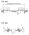
- FIG. 9( a ) is a view showing the cross section of the piezoelectric speaker
- FIG. 9( b ) is a view showing the vibration model of the piezoelectric speaker.
- FIG. 10( a ) is a view showing the displacement of a piezoelectric vibrating body in a vibration mode at its resonance frequency
- FIGS. 10( b ) and 10 ( c ) are views showing the displacement of a piezoelectric vibrating body in vibration modes at frequencies other than its resonance frequency.
- FIG. 11 is a graph showing the relationship between a change in the diameter of a piezoelectric body and the resonance frequency thereof.
- FIG. 12 is a graph showing the relationship between a sound pressure level and a frequency when the diameter of a piezoelectric body is changed.
- FIG. 13( a ) is a view showing the vibration state of a piezoelectric speaker according to a second embodiment
- FIG. 13( b ) is a view showing the vibration waveform of the piezoelectric speaker
- FIG. 13( c ) is a cross-sectional view of the main part of the piezoelectric speaker.
- FIG. 14 is a graph showing a change in the sound pressure level with respect to a frequency in a third embodiment of the invention, when no film-shaped body is attached, when a film-shaped body is attached, and when a film-shaped body having an in-phase mode bellows structure is attached.
- FIG. 15 is a graph showing the main part of the above graph in an enlarged scale.
- FIG. 16 is a cross-sectional view showing the main part of a piezoelectric speaker according to a fourth embodiment of the invention.
- FIG. 17 is an exploded perspective view showing a fire alarm using a piezoelectric speaker according to a fifth embodiment of the invention.
- FIG. 18 is an enlarged cross-sectional view of the main part of the above drawing.
- FIGS. 19( a ) to 19 ( c ) are views showing a piezoelectric audio device according to a sixth embodiment of the invention, in which FIG. 19( a ) is a configuration view, FIG. 19( b ) is a cross-sectional view of the piezoelectric audio device, and FIG. 19( c ) is an exploded perspective view of the piezoelectric audio device.
- FIG. 20 is a configuration view of a piezoelectric speaker of the piezoelectric audio device.
- FIG. 21 is a graph showing a variation in a sound pressure level when a film-shaped body of the piezoelectric speaker has a bellows structure and when the film-shaped body does not have a bellows structure.
- FIG. 22 is a graph showing a variation in a sound pressure level when the piezoelectric audio device has a resonator and when the piezoelectric audio device does not have a resonator.
- FIG. 23 is a view showing the structure of a resonator of the piezoelectric audio device and a calculation expression of the resonance frequency thereof.
- FIGS. 24( a ) and 24 ( b ) are cross-sectional views of a film-shaped body according to a first modification.
- FIG. 25 is a cross-sectional view of a film-shaped body and a frame according to a second modification.
- FIGS. 26( a ) to 26 ( c ) are views showing a third modification, in which FIG. 26( a ) is a partial cross-sectional view of a frame of the modification, FIG. 26( b ) is a cross-sectional view when an adhesive agent is being filled in the frame, and FIG. 26( c ) is a plan view when an adhesive agent has been filled in the frame.
- FIGS. 27( a ) and 27 ( b ) are views showing a fourth modification, in which FIG. 27( a ) is a configuration view of a piezoelectric vibrator according to the modification, and FIG. 27( b ) is a graph showing a variation in the resonance frequency when the diameter of a piezoelectric body is changed.
- FIG. 28 is a cross-sectional view of a piezoelectric speaker according to a fifth modification.
- FIGS. 29( a ) and 29 ( b ) are views showing a sixth modification, in which FIG. 29( a ) is a configuration view of a piezoelectric audio device according to the modification, and FIG. 29( b ) is a cross-sectional view of the piezoelectric audio device.
- FIGS. 30( a ) and 30 ( b ) are views showing a seventh modification, in which FIG. 30( a ) is a configuration view of a piezoelectric audio device according to the modification, and FIG. 30( b ) is a cross-sectional view of the piezoelectric audio device.
- FIG. 31 is a graph showing directivity of a radiation sound in the piezoelectric audio device.
- FIG. 32 is a cross-sectional view of a piezoelectric audio device according to an eighth modification.
- FIG. 33 is a graph showing a variation in a sound pressure level when the piezoelectric audio device has a duct, and when the piezoelectric audio device does not have a duct.
- FIG. 34 is a cross-sectional view of a piezoelectric audio device according to a ninth modification.
- FIG. 35 is a perspective view of a duct of a piezoelectric audio device according to the ninth modification.
- FIG. 36 is a graph showing a variation in a sound pressure level when the piezoelectric audio device has a duct, and when the piezoelectric audio device does not have a duct.
- a piezoelectric speaker 1 includes a piezoelectric vibrator 2 , a film-shaped body 3 provided around the piezoelectric vibrator 2 so as to hold the piezoelectric vibrator 2 , and a frame 4 supporting the outer periphery of the film-shaped body 3 .
- the film-shaped body 3 is configured by a bellows structure which has a mountain portion and a valley portion in a circumferential direction so as to correspond to a natural frequency of an in-phase mode wherein antinodes and nodes are formed in a concentric form.
- the piezoelectric vibrator and the film-shaped body form a sound producing body.
- the piezoelectric vibrator 2 includes a piezoelectric body 21 formed of a piezoelectric element and a metal plate used as a plate-shaped body 22 which has a larger diameter than the piezoelectric body 21 and which is concentrically attached to a surface of the piezoelectric body 21 .
- the piezoelectric body 21 is a lead zirconium titanate having a thickness of 0.05 to 0.1 mm and a density of 8.0 (1E+3 kg/m 3 ), for example.
- the plate-shaped body 22 is a 42-nickel alloy (an iron-nickel alloy containing 42% of nickel) having a thickness of 0.05 to 0.1 mm and a density of 8.15 (1E+3 kg/m 3 ), for example.
- the piezoelectric body 21 and the plate-shaped body 22 have the same thickness.
- the piezoelectric body 21 and the plate-shaped body 22 have their entire surface adhesively attached by an adhesive agent made of an epoxy resin, for example.
- a silver electrode is formed on the surface of the piezoelectric body 21 and is connected to a lead wire (not shown) through a lead-free solder. When a signal voltage is applied to the electrode, the piezoelectric body 21 is deformed, and the vibration thereof is emitted as sound (vibration of air).
- the film-shaped body 3 is a thin member that elastically holds the piezoelectric vibrator 2 , and is a resin film such as PEI (polyetherimide), PEN (polyether naphthalate), or PC (polycarbonate), having a thickness of 50 to 188 ⁇ m, for example.
- the film-shaped body 3 forms a bellows structure which has a doughnut shape, in which the piezoelectric vibrator 2 is attached at the center by an adhesive agent, and which has a mountain portion and a valley portion corresponding to the natural frequency in the circumferential direction as described above.
- a resonance frequency is used for the purpose of receiving signals of the frequencies 2 kHz to 4 kHz, and the distance ⁇ between the mountain portion 3 M and the valley portion 3 V is set to about 0.7 mm.
- the bellows structure of the film-shaped body 3 is elastically supported by the frame 4 used as a supporting portion through an elastic body (elastomer) 50 , and is configured such that the antinodes of the bellows are identical to the apexes of the antinodes of a vibration mode (the in-phase mode of the natural frequency). Thus, it is possible to further increase a displacement in the vibration mode.
- the natural frequency is set to be a resonance point between the frequencies of 2 kHz to 4 kHz.
- the frequency range is set to its maximum loudness, it is possible to emit a sensation of loud sound.
- the bellows structure may have a configuration in which the valley portion 3 V and the mountain portion 3 M are alternately formed in that order from the side of the frame 4 as shown in FIG. 6( a ) and may have a configuration in which the mountain portion 3 M and the valley portion 3 V are alternately formed in that order from the side of the frame 4 as shown in FIG. 6( b ). Moreover, the bellows structure may include only the valley portion 3 V as shown in FIG. 6( c ), and may include only the mountain portion 3 M as shown in FIG. 6( d ).
- the film-shaped body 3 is a resin film and is molded by a heated mold as an example of a molding method.
- the film-shaped body 3 is placed between a mold A and a rubber member B, and the mold A is heated to a predetermined temperature.
- the mold A is processed to have the shape of the bellows.
- the mold A is pressed against the rubber member B with the film-shaped body 3 disposed therebetween.
- the mold A is opened so as to remove the film-shaped body 3 .
- the film-shaped body 3 is shaped into the bellows structure in accordance with the shape of the mold.
- the frame 4 is formed of a resin, for example and provided around the film-shaped body 3 , and has a flat surface where the film-shaped body 3 is placed. On this flat surface, the film-shaped body 3 is elastically held by the elastic body 50 as described above.
- FIGS. 8( a ) to 8 ( c ) show a vibration mode ( FIG. 8( a )), the configuration of the film-shaped body ( FIG. 8( b )), and the sound pressure output of the piezoelectric speaker 1 ( FIG. 8( c )) when the mountain portion 3 M and the valley portion 3 V of the bellows structure of the film-shaped body 3 are formed at positions corresponding to the antinodes of the resonance frequency of the in-phase mode.
- the piezoelectric body 21 is contracted and expanded when a signal voltage of a radiation sound is applied to the piezoelectric body 21 , since the plate-shaped body 22 formed of a metal plate, to which the piezoelectric body 21 is attached, is not contracted and expanded, the piezoelectric vibrator 2 recurves.
- the piezoelectric vibrator 2 vibrates by repeating this recurving operation and emits a radiation sound.
- the film-shaped body 3 having the bellows structure the film-shaped body 3 is likely to recurve at the position of the bellows structure, and is likely to be expanded and contracted in the circumferential direction when the bellows structure recurves.
- the amplitude of the piezoelectric vibrator 2 at a target natural frequency increases as depicted by curve ‘a’ in FIG. 8( c ), and the sound pressure level of the radiation sound emitted by the piezoelectric speaker 1 increases.
- FIG. 9( a ) shows the cross section of the piezoelectric speaker 1
- FIG. 9( b ) is a modeling diagram of the piezoelectric speaker 1
- the bellows structure of the film-shaped body 3 is not illustrated.
- the piezoelectric speaker 1 without the bellows structure, of which the measurement results are depicted by curve ‘b’ in FIG. 8( c ) has a configuration in which the outer diameter of the film-shaped body 3 is 53 mm, the radial length L 1 of the film-shaped body 3 is 7 mm, and the resonance frequency f 1 is 180 Hz.
- the piezoelectric speaker 1 having the bellows structure depicted by curve ‘a’ has a configuration in which the outer diameter of the film-shaped body 3 is 50 mm, and the radial length L 2 of the film-shaped body 3 is 6 mm.
- the resonance frequency f 2 is about 1.2 times the resonance frequency f 1 , peaks having high sound pressure levels appear near 210 Hz and 100 Hz.
- the sound pressure level can be increased by increasing the outer diameter of the film-shaped body 3 .
- the sound pressure level at any frequency domain can be increased by changing the Young's modulus, thickness, and radial length of the film-shaped body 3 to thereby change the resonance frequency.
- the bellows structure of the film-shaped body 3 has a configuration in which the antinodes of the bellows are identical to the apexes of the antinodes of the vibration mode (the in-phase mode of the natural frequency).
- the antinodes and nodes of the vibration are formed in a concentric form.
- the displacement is dispersed as shown in FIGS. 10( b ) and 10 ( c ).
- the displacement in the vibration mode can be further increased when the vibration mode becomes the in-phase mode.
- the plate-shaped body 22 and the piezoelectric body 21 formed of a metal plate have an approximately disc shape, and the ratio R:r of the radius of the plate-shaped body 22 to that of the piezoelectric body 21 is set to 10:4.
- FIG. 11 shows a change in the resonance frequency when the diameter of the piezoelectric body 21 is changed with the diameter of the plate-shaped body 22 maintained to be constant.
- the piezoelectric body 21 and the plate-shaped body 22 are circular, and the diameter of the plate-shaped body 22 is 50 mm.
- the resonance frequency is the lowest when the diameter of the piezoelectric body 21 is near 23 mm, and in this case, the ratio of the radius of the plate-shaped body 22 to that of the piezoelectric body 21 is about 10:4.
- the ratio of the radius of the plate-shaped body 22 to that of the piezoelectric body 21 is preferably about 10:4. Therefore, since the resonance frequency of the piezoelectric speaker 1 decreases when the configuration of the present embodiment is used, it is possible to increase the sound pressure level at a low-frequency band.
- the plate-shaped body is not limited to the metal plate but may be a material (for example, a uni-morph type material) in which a flexed state is created when a piezoelectric element is expanded and contracted within a plane.
- the bellows structure of the film-shaped body 3 has a configuration in which the bellows and the antinodes of the vibration mode correspond to each other in a one-to-one correspondence, and no bellows (the mountain portion and the valley portion) is present at the positions of the nodes of the vibration mode.
- the piezoelectric speaker has the same structure as the first embodiment except for the shape of the bellows.
- FIGS. 13( a ) to 13 ( c ) show a vibration mode ( FIG. 13( a )), the displacement of the vibrating portion of the piezoelectric speaker ( FIG. 13( b )), and the configuration of the film-shaped body ( FIG. 13( c )) when the mountain portion 3 M and the valley portion 3 V of the bellows structure of the film-shaped body 3 are formed so as to correspond to the antinodes of the resonance frequency of the in-phase mode in a one-to-one correspondence.
- the piezoelectric body 21 is contracted and expanded when a signal voltage of a radiation sound is applied to the piezoelectric body 21 , since the plate-shaped body 22 to which the piezoelectric body 21 is attached is not contracted and expanded, the piezoelectric vibrator 2 recurves.
- the piezoelectric vibrator 2 vibrates by repeating this recurving operation and emits a radiation sound.
- the film-shaped body 3 having the bellows structure the film-shaped body 3 is likely to recurve at the position of the bellows structure, and is likely to be expanded and contracted in the circumferential direction when the bellows structure recurves.
- vibration occurs in a concentric form as shown in FIG. 13( a ), and thus, antinodes and nodes of the vibration can be made to occur alternately. Therefore, as shown in FIG. 13( b ), the displacement of the film-shaped body 3 is large at the position of the piezoelectric element, and the vibration displacement propagates in a one-to-one correspondence to the bellows structure in which the bellows is formed around the piezoelectric element to form the mountain portion 3 M and the valley portion 3 V.
- the amplitude of the piezoelectric vibrator 2 at a target natural frequency increases as depicted by a curve in FIG. 13( b ), and it is possible to further increase the sound pressure level of the radiation sound emitted by the piezoelectric speaker 1 .
- FIG. 14 The measurement results of the relationship between the sound pressure level and the resonance frequency are shown in FIG. 14 .
- the same piezoelectric vibrator 2 as the first embodiment shown in FIGS. 1 to 4 is formed to a size of 35 ⁇ .
- curve ‘a’ shows a case of only the 35 ⁇ piezoelectric vibrator 2
- curve ‘b’ shows a case when a 50 ⁇ film-shaped body 3 is connected to the 354 piezoelectric vibrator 2
- curve ‘c’ shows a case when a 50 ⁇ film-shaped body 3 having a bellows is connected to the 35 ⁇ piezoelectric vibrator 2 .
- FIG. 15 is an enlarged view near the 3rd-order resonance point.
- paper made of wood pulp and paper made of non-wood plant such as paper mulberry, paper bush, or bamboo may be used as the film-shaped body in addition to a resin film.
- a nonwoven fabric a material in which an adhesive agent is impregnated into a nonwoven fabric so as to enhance rigidity, a material in which urethane is coated on polyester, titanium, aluminum, and the like may be used.
- a piezoelectric speaker 1 S of the present embodiment doping is performed on a flat film-shaped body 3 as shown in FIG. 16 , which does not have a bellows structure, so as to form doping regions 3 D.
- doping is performed on a flat film-shaped body 3 as shown in FIG. 16 , which does not have a bellows structure, so as to form doping regions 3 D.
- regions having a high elastic modulus it is possible to form a piezoelectric speaker in which the doping regions 3 D become nodes so as to correspond to the resonance frequency.
- paper made of wood pulp and paper made of non-wood plant such as paper mulberry, paper bush, or bamboo may be used as the film-shaped body in addition to a resin film.
- a nonwoven fabric a material in which an adhesive agent is impregnated into a nonwoven fabric in a concentric form at predetermined intervals corresponding to the resonance frequency so as to enhance rigidity to thereby form regions having a high Young's modulus, a material in which urethane is selectively coated on polyether in a concentric form at predetermined intervals corresponding to the resonance frequency, a material in which impurities are selectively doped into titanium, aluminum, or the like in a concentric form at predetermined intervals corresponding to the resonance frequency so as to change the properties thereof, and the like may be used.
- regions serving as antinodes may be configured by thin regions so that the elastic modulus thereof is lower than other regions.
- a laser beam may be selectively emitted to titanium, aluminum, or the like in a concentric form at predetermined intervals corresponding to the resonance frequency so as to evaporate a part thereof and form thin regions.
- the piezoelectric speaker is likely to resonate, and it is possible to increase the displacement and obtain a higher sound pressure level.
- the fire alarm is configured such that when a fire breaks out, a smoke detector detects smoke and informs residents about the fire by outputting sound (a warning sound such as “Beep, Beep, Beep” or an alarm voice such as “Fire has broken out” or “Battery has been exhausted”).
- a piezoelectric speaker 1 is inserted between a body 103 and an optical smoke detector 102 , and is attached to a base 105 together with a rear cover 104 and a battery 106 .
- Reference numeral 101 is a cover having a hole H.
- the smoke detector is configured by the optical smoke detector 102 and has a configuration in which a change in the voltage from a smoke detection sensor is captured into one of the terminals of a device chip having an ADC (analog/digital conversion) function.
- the captured signal is internally processed, and a buzzer outputs sound when the signal level reaches a predetermined level or higher.
- the buzzer output is amplified by the piezoelectric speaker 1 . That is, a through hole having a predetermined size is drilled through the center of the optical smoke detector 102 along its longitudinal direction.
- a high-brightness LED transmission element
- a phototransistor rejection element
- These two transmission and reception elements are spaced by about 70 mm in terms of a tip-to-tip distance.
- a hole having the same size of 4.2 mm is drilled through the central portion of the square-shaped member in a direction orthogonal to the longitudinal through hole.
- Smoke passes through this hole to block light from the LED, which decreases the amount of light reaching the phototransistor and increases the voltage value input to the terminal.
- a VR (10K) of a light source LED is adjusted to about 6.8 KW to supply current of 0.37 mA to the LED.
- the voltage value input to the device chip is around 0.6 V when there is no smoke and increases up to about 3 V (maximum) when smoke enters. That is, the presence of smoke is detected by a difference in the voltage values.
- a counter measures duration of this state.
- sound a warning sound such as “Beep, Beep, Beep”
- the warning sound is continuously output.
- the piezoelectric speaker has the film-shaped body 3 having the same bellows structure as described in the first embodiment.
- the elastic body 50 which is molded at the same time as a cover or a body formed of a thermoplastic elastomeric ABS resin
- a ring-shaped elastomer is attached to the cover or the body 103 (formed of an ABS resin), and the film-shaped body 3 is inserted.
- the piezoelectric speaker has weak binding force and high acoustic impedance as compared to the fixing method using an adhesive agent.
- the residential fire alarm includes a module or the like for detecting smoke in an optical method as the optical smoke detector 102 in addition to the speaker.
- the elastic body for supporting the film-shaped body with respect to the frame is not limited to the thermoplastic elastomer, but an elastic body such as polyurethane foam may be used.
- the invention is not limited to the fire alarm, but can be applied to an alert device that outputs a warning sound in accordance with detection results of various sensors such as an alert device attached to the door of a refrigerator or an abnormality alarm of a washing machine.
- the film-shaped body 3 is provided on the entire periphery of the piezoelectric vibrator 2 so as to hold the piezoelectric vibrator 2 , the film-shaped body 3 may be provided on a part of the periphery of the piezoelectric vibrator 2 .
- the way in which the piezoelectric speaker configured by the piezoelectric vibrator is mounted is not limited to the embodiments described above but may be changed appropriately.
- a piezoelectric audio device 10 according to a sixth embodiment of the invention will be described with reference to FIGS. 19 to 21 .
- a piezoelectric audio device 10 according to the present embodiment includes a piezoelectric speaker 1 , a resonator 30 that resonates with a radiation sound emitted by the piezoelectric speaker 1 , a reflection plate 40 that reflects the radiation sound toward the front side, and a housing 5 that holds these elements.
- the piezoelectric speaker 1 includes a piezoelectric vibrator 2 , a film-shaped body 3 that is provided around the piezoelectric vibrator 2 so as to hold the piezoelectric vibrator 2 , and a frame 23 that supports the outer periphery of the film-shaped body 3 .
- the piezoelectric vibrator 2 includes a piezoelectric body 21 formed of a piezoelectric element and a metal plate used as a plate-shaped body 22 which has a larger diameter than the piezoelectric body 21 and which is concentrically attached to a surface of the piezoelectric body 21 .
- the piezoelectric body 21 is a lead zirconium titanate having a thickness of 0.05 to 0.1 mm, for example.
- the plate-shaped body 22 is a 42-nickel alloy (an iron-nickel alloy containing 42% of nickel) having a thickness of 0.05 to 0.1 mm, for example.
- the piezoelectric body 21 and the plate-shaped body 22 have the same thickness.
- the piezoelectric body 21 and the plate-shaped body 22 are attached to each other by an adhesive agent made of an epoxy resin, for example.
- a silver electrode is formed on the surface of the piezoelectric body 21 and is connected to a lead wire (not shown). When a signal voltage is applied to the electrode, the piezoelectric body 21 is deformed, and the vibration thereof is emitted as sound (vibration of air).
- the film-shaped body 3 is a thin member that elastically holds the piezoelectric vibrator 2 , and is a resin film such as PEI (polyetherimide) or PEN (polyether naphthalate), having a thickness of 75 to 188 ⁇ m, for example.
- the film-shaped body 3 has a bellows structure which has a doughnut shape, in which the piezoelectric vibrator 2 is attached at the center by an adhesive agent, and which is formed in the circumferential direction.
- the bellows structure may have a configuration in which a valley portion and a mountain portion are alternately formed as shown in FIGS. 6( a ) and 6 ( b ) of the first embodiment, and the bellows structure may include only the valley portion as shown in FIG. 21C , and may include only the mountain portion as shown in FIG. 21D .
- the frame 23 is a bottomed cylindrical body which is formed of a resin, for example, and of which one opening is open.
- the frame 23 adhesively supports the periphery of the film-shaped body 3 in the flat surface of a step formed on the inner wall of the cylindrical body, and a posterior air chamber 61 is formed between the film-shaped body 3 and the bottom surface.
- the resonator 30 is cap shaped and has a sound hole 31 at the center.
- the resonator 30 is provided so as to cover the opening of the frame 23 , and an anterior air chamber 62 is formed between the film-shaped body 3 and the resonator 30 .
- the posterior air chamber 61 and the anterior air chamber 62 reflect the radiation sound emitted by the piezoelectric vibrator 2 so as to increase the sound pressure level.
- the reflection plate 40 has an outer circumference 41 which is erected toward the front side.
- FIG. 14 shows the sound pressure level of the piezoelectric speaker 1 when the film-shaped body 3 has the bellows structure and when the film-shaped body 3 does not have the bellows structure.
- the piezoelectric body 21 is contracted and expanded when a signal voltage of a radiation sound is applied to the piezoelectric body 21 , since the plate-shaped body 22 to which the piezoelectric body 21 is attached is not contracted and expanded, the piezoelectric vibrator 2 recurves.
- the piezoelectric vibrator 2 vibrates by repeating this recurving operation and emits a radiation sound.
- the film-shaped body 3 having the bellows structure the film-shaped body 3 is likely to recurve at the position of the bellows structure, and is likely to be expanded and contracted in the circumferential direction when the bellows structure recurves.
- the amplitude of the piezoelectric vibrator 2 increases, and the sound pressure level of the radiation sound emitted by the piezoelectric speaker 1 increases over a low-frequency domain (hereinafter referred to as a low-frequency band) and a high-frequency domain (hereinafter referred to as a high-frequency band).
- FIG. 9( a ) shows the cross section of the piezoelectric speaker 1
- FIG. 9( b ) is a modeling diagram of the piezoelectric speaker 1
- the bellows structure of the film-shaped body 3 is not illustrated.
- FIG. 22 shows the sound pressure level at the respective frequencies of the piezoelectric audio device 10 with and without the resonator 30
- FIG. 23 shows the structure of the resonator 30 and a calculation expression of the resonance frequency thereof.
- the data regarding the case of ‘With Resonator 30 ’ in FIG. 22 are data when the resonator 30 is configured so that the resonance frequency f cav of the anterior air chamber 62 becomes 3000 Hz.
- the resonance frequency f cav of the anterior air chamber 62 is expressed by the following expression.
- the resonator 30 By changing the configuration of the resonator 30 , it is possible to adjust the resonance frequency of the resonator 30 .
- the sound pressure level is increased in the range of about 1000 to 4000 Hz as compared to the case of ‘Without Resonator 30 ’. Since the piezoelectric speaker 1 is incorporated into the piezoelectric audio device 10 of the present embodiment, it is possible to obtain a high sound pressure level in the low-frequency band and the high-frequency band.
- the resonator 30 enables the sound pressure level to be increased at any frequency.
- FIGS. 24( a ) and 24 ( b ) show a first modification.
- the film-shaped body 3 has a step-shaped portion 3 a which is disposed at a position where the piezoelectric vibrator 2 is held.
- the inner diameter of the step-shaped portion 3 a has a size such that it engages with the piezoelectric vibrator 2 from the periphery, and the film-shaped body 3 is adhesively attached to the piezoelectric vibrator 2 in a state where the piezoelectric vibrator 2 is engaged.
- the piezoelectric vibrator 2 is reliably attached to the film-shaped body 3 , and the attachment position becomes constant.
- the sound pressure level and the resonance frequency of the radiation sound emitted by the piezoelectric speaker 1 are stabilized.
- FIG. 25 shows a second modification.
- the frame 23 has an L-shaped portion 23 a in a cross-sectional view thereof which is disposed at a position where the film-shaped body 3 is supported.
- the L-shaped portion 23 a has an L-shape on the vertical cross section, and the film-shaped body 3 is placed on that portion so as to be engaged and supported.
- the inner diameter of the vertical portion of the L-shape has a size such that it engages with the film-shaped body 3 from the periphery, and the frame 23 is adhesively attached to the film-shaped body 3 in a state where the film-shaped body 3 is engaged.
- the film-shaped body 3 is reliably attached to the frame 23 , and the attachment position becomes constant.
- the sound pressure level and the resonance frequency of the radiation sound emitted by the piezoelectric speaker 1 are stabilized.
- FIGS. 26( a ) to 26 ( c ) show a third modification.
- the frame 23 further includes a notch 23 b that is formed on a surface on which the L-shaped film-shaped body 3 is placed, and an adhesive agent C is filled into the notch 23 b using a dispenser D.
- the applied adhesive agent C is deposited into the notch 23 b , and the film-shaped body 3 can be adhesively attached without floating.
- the film-shaped body 3 is reliably attached to the frame 23 , and the sound pressure level and the resonance frequency of the radiation sound emitted by the piezoelectric speaker 1 are stabilized.
- FIG. 27( a ) shows a fourth modification.
- the plate-shaped body 22 and the piezoelectric body 21 have an approximately disc shape, and the ratio of the radius of the plate-shaped body 22 to that of the piezoelectric body 21 is set to approximately 10:7.
- FIG. 27( b ) shows a change in the resonance frequency when the diameter of the piezoelectric body 21 is changed with the diameter of the plate-shaped body 22 maintained to be constant.
- the piezoelectric body 21 and the plate-shaped body 22 are circular, and the diameter of the plate-shaped body 22 is 50 mm.
- the resonance frequency is the lowest when the diameter of the piezoelectric body 21 is near 35 mm, and in this case, the ratio of the radius of the plate-shaped body 22 to that of the piezoelectric body 21 is about 10:7.
- the ratio of the radius of the plate-shaped body 22 to that of the piezoelectric body 21 is preferably between 10:6 and 10:8. Therefore, since the resonance frequency of the piezoelectric speaker 1 decreases when the configuration of this modification is used, it is possible to increase the sound pressure level at a low-frequency band.
- FIG. 28 shows a fifth modification.
- the film-shaped body 3 covers the piezoelectric vibrator 2 , and an air layer E is provided between the film-shaped body 3 and the piezoelectric vibrator 2 .
- the acoustic impedance of air is far lower than the acoustic impedance of the plate-shaped body 22 .
- the film-shaped body 3 so as to form the air layer E on the entire surface of the piezoelectric vibrator 2 , it is possible to decrease the acoustic impedance of the plate-shaped body 22 .
- the radiation sound emitted by the piezoelectric vibrator 2 can be transmitted toward the front side without attenuation, it is possible to increase the sound pressure level.
- FIGS. 29( a ) and 29 ( b ) show a sixth modification.
- the outer circumference 41 of the reflection plate 40 has a shape such that it is erected toward the front side with an approximately exponential curve. In the exponential curve portion, the radiation sound is not likely to resonate.
- the reflection plate 40 has an approximately rectangular shape or an approximately elliptical shape, the directivity of the radiation sound is different in the longitudinal direction and the lateral direction of the reflection plate 40 .
- the outer circumference 41 of the reflection plate 40 has an approximately exponential curve, the radiation sound is not likely to resonate in the outer circumference.
- the difference in the directivity of the radiation sound can be further decreased when the air hole 31 of the resonator 30 is formed between the opening position of the frame 23 and the upper end position of the outer circumference of the reflection plate 40 in the front-to-rear direction of the piezoelectric audio device 10 .
- FIGS. 30( a ) and 30 ( b ) show a seventh modification.
- the piezoelectric audio device 10 includes a plate-shaped horn cap 7 that is provided on the front side of the resonator 30 so as to adjust the directivity of the radiation sound.
- the horn cap 7 is bent toward the resonator 30 and is supported by columnar supports 71 that are formed on the reflection plate 40 .
- FIG. 31 shows the directivity of the radiation sound when the horn cap 7 is attached.
- the sound pressure levels in directions of 15°, 45°, and 90° are shown wherein the front direction of the piezoelectric audio device 10 is 90°, and the direction vertical to the front direction is 0°.
- the directivity can be changed by changing the length of the columnar supports 71 .
- the directivity is flattened when the length is decreased, and the directivity is sharpened when the length is increased.
- FIG. 32 shows an eighth modification.
- the piezoelectric audio device 10 includes a duct 8 that connects the front space of the reflection plate 40 and the posterior air chamber 61 , and the resonance frequency of the piezoelectric audio device 10 is adjusted by the duct 8 .
- the duct 8 is provided so as to extend from a side surface of the cylindrical body of the frame 23 to the bottom surface of the reflection plate 40 , and a plurality of ducts 8 may be formed.
- the duct 8 releases the radiation sound reflected by the posterior air chamber 61 toward the front side of the reflection plate 40 .
- By changing the cross-sectional area and the length of the duct 8 it is possible to change the resonance frequency of the duct 8 .
- FIG. 33 shows examples of the sound pressure level of the piezoelectric audio device 10 with and without the duct 8 , and a part of the graph is shown in an enlarged view.
- Three data in which the duct 8 has different cross-sectional areas are shown for the case of ‘With Duct 8 ’. Since the shape of the duct 8 is limited by the shape of the piezoelectric audio device 10 , and an overall shape thereof is determined, the resonance frequency of the duct 8 is mainly in the low-frequency band. In the example of FIG. 33 , the sound pressure level in the low-frequency band increases. Moreover, the peak frequency of the sound pressure level is different depending on the size of the cross-sectional area of the duct 8 .
- the peak frequency moves toward the high-frequency band as the cross-sectional area increases.
- FIGS. 34 and 35 show a ninth modification.
- the piezoelectric audio device 10 has the horn cap 7 similarly to the piezoelectric audio device of the seventh modification, and the propagation direction of the sound from the piezoelectric audio device 10 is adjusted by the horn cap.
- a partition formed of a flat plate 72 is disposed on the rear side of the horn cap. The presence of the flat plate 72 suppresses the propagation in the vertical direction, namely in the ceiling-to-floor direction so as to be converted into a propagation in the horizontal direction.
- Reference numeral 5 is the housing, and reference numeral 2 is the piezoelectric vibrator.
- FIG. 36 shows examples of the sound pressure level of the piezoelectric audio device 10 when the horn cap 7 has the flat plate 72 and when the horn cap 7 does not have the flat plate 72 .
- the sound pressure level in directions having an angle is decreased as compared to curve ‘b’ for the case when the horn cap does not have the flat plate. That is, the propagation rate in the horizontal direction is increased by that amount. Accordingly, this modification is ideal for products which are installed on a wall.
- the film-shaped body 3 is provided on the entire periphery of the piezoelectric vibrator 2 so as to hold the piezoelectric vibrator 2 , the film-shaped body 3 may be provided on a part of the periphery of the piezoelectric vibrator 2 .
- a resin film paper made of wood pulp, paper made of non-wood plant such as paper mulberry, paper bush, or bamboo, a nonwoven fabric, a material in which an adhesive agent is impregnated into a nonwoven fabric so as to enhance rigidity, a material in which urethane is coated on polyester, titanium, aluminum, and the like may be used as the film-shaped body.
- the thickness of the film-shaped body is not particularly limited, and the thickness and the material thereof are preferably selected from the perspective of using a membrane that is easy to vibrate.
Landscapes
- Physics & Mathematics (AREA)
- Engineering & Computer Science (AREA)
- Acoustics & Sound (AREA)
- Signal Processing (AREA)
- Piezo-Electric Transducers For Audible Bands (AREA)
Abstract
Description
f=1/(2π)·(k/m)1/2
f 0=1/(2π)·(k 0 /m 0)1/2
k 0 =E·h 3 /L 2/4
f 2 /f 1 =L 1 /L 2=7/6
f=1/(2π)·(k/m)1/2
f 0=1/(2π)·(k 0 /m 0)1/2
k 0 =E·h 3 /L 2/4
f d=160(D/V c/(L+r)1/2
-
- 1: Piezoelectric Speaker
- 2: Piezoelectric Vibrator
- 3: Film-Shaped Body (Resonator)
- 3M: Mountain Portion
- 3V: Valley Portion
- 3F: Antinodes
- 3D: Doping Region
- 4: Frame
- 5: Housing
- 7: Horn Cap
- 8: Duct
- 10: Piezoelectric Audio Device
- 21: Piezoelectric Body
- 22: Plate-Shaped Body
- 23: Frame
- 31: Sound Hole
- 40: Reflection Plate
- 41: Outer Circumference
- 50: Elastic Body
- 61: Posterior Air Chamber
- 62: Anterior Air Chamber
- 72: Flat Plate
- 103: Body
- 102: Optical Smoke Detector
- 104: Rear Cover
- 105: Base
- 106: Battery
- 101: Cover
- H: Hole
Claims (10)
Applications Claiming Priority (7)
| Application Number | Priority Date | Filing Date | Title |
|---|---|---|---|
| JP2008-334854 | 2008-12-26 | ||
| JP2008334854A JP5796169B2 (en) | 2008-12-26 | 2008-12-26 | Piezoelectric speaker |
| JP2008-334872 | 2008-12-26 | ||
| JP2008334872A JP5796170B2 (en) | 2008-12-26 | 2008-12-26 | Piezoelectric sound device |
| JP2009246392A JP5669078B2 (en) | 2009-10-27 | 2009-10-27 | Piezoelectric speaker and sensor with alarm using the same |
| JP2009-246392 | 2009-10-27 | ||
| PCT/JP2009/071550 WO2010074206A1 (en) | 2008-12-26 | 2009-12-25 | Piezoelectric speaker, piezoelectric audio device employing piezoelectric speaker, and sensor with alert device attached |
Publications (2)
| Publication Number | Publication Date |
|---|---|
| US20110255718A1 US20110255718A1 (en) | 2011-10-20 |
| US9031265B2 true US9031265B2 (en) | 2015-05-12 |
Family
ID=42287811
Family Applications (1)
| Application Number | Title | Priority Date | Filing Date |
|---|---|---|---|
| US13/142,003 Expired - Fee Related US9031265B2 (en) | 2008-12-26 | 2009-12-25 | Piezoelectric speaker, piezoelectric audio device employing piezoelectric speaker, and sensor with alert device attached |
Country Status (5)
| Country | Link |
|---|---|
| US (1) | US9031265B2 (en) |
| EP (1) | EP2373057B1 (en) |
| CN (1) | CN102265646B (en) |
| CA (1) | CA2748252C (en) |
| WO (1) | WO2010074206A1 (en) |
Cited By (3)
| Publication number | Priority date | Publication date | Assignee | Title |
|---|---|---|---|---|
| US20150028721A1 (en) * | 2012-03-30 | 2015-01-29 | Kyocera Corporation | Vibration device and portable terminal employing the same |
| US10123128B2 (en) | 2016-09-07 | 2018-11-06 | Microsoft Technology Licensing, Llc | Speaker arrangement |
| US11598979B1 (en) * | 2020-03-30 | 2023-03-07 | Snap Inc. | Dual port constrained acoustic volume |
Families Citing this family (20)
| Publication number | Priority date | Publication date | Assignee | Title |
|---|---|---|---|---|
| CN102668598B (en) * | 2009-12-15 | 2015-03-04 | 日本电气株式会社 | Actuator, piezoelectric actuator, electronic device, and method for damping and reversing vibration |
| CN103814586B (en) | 2011-09-22 | 2016-10-26 | 松下知识产权经营株式会社 | Directional loudspeaker |
| JP6010762B2 (en) * | 2011-12-27 | 2016-10-19 | パナソニックIpマネジメント株式会社 | Hermetic compressor and refrigerator including the same |
| GB201207045D0 (en) | 2012-04-23 | 2012-06-06 | Hiwave Technologies Uk Ltd | Transducers with improved impedance matching |
| US10034049B1 (en) | 2012-07-18 | 2018-07-24 | Google Llc | Audience attendance monitoring through facial recognition |
| US9106994B2 (en) * | 2013-03-14 | 2015-08-11 | Abatech Electronics Co., Ltd. | Ultra-slim speaker structure |
| US8810426B1 (en) * | 2013-04-28 | 2014-08-19 | Gary Jay Morris | Life safety device with compact circumferential acoustic resonator |
| CN103347237A (en) * | 2013-07-05 | 2013-10-09 | 西安康弘新材料科技有限公司 | Piezoelectric ceramic flat loudspeaker vibrator and installation structure thereof |
| CN103796120A (en) * | 2013-10-28 | 2014-05-14 | 广州市番禺奥迪威电子有限公司 | Piezoelectric receiver |
| TWI533714B (en) | 2014-04-18 | 2016-05-11 | 財團法人工業技術研究院 | Piezoelectric electroacoustic transducer |
| GB201409547D0 (en) * | 2014-05-29 | 2014-07-16 | Gill Instr Ltd | An electroacoustic transducer |
| TWM508177U (en) * | 2015-04-24 | 2015-09-01 | Ibase Technology Inc | Electronic device with transparent speaker |
| CN104936085A (en) * | 2015-05-28 | 2015-09-23 | 常州泰勒维克今创电子有限公司 | High-speed rail broadcast noise reduction apparatus |
| WO2016194683A1 (en) * | 2015-05-30 | 2016-12-08 | 第一精工株式会社 | Speaker |
| JP6493929B2 (en) * | 2017-03-01 | 2019-04-03 | 株式会社今仙電機製作所 | Electronic horn |
| US11252510B2 (en) * | 2017-11-21 | 2022-02-15 | Nitto Denko Corporation | Piezoelectric speaker-forming laminate |
| CN111770421A (en) * | 2020-06-30 | 2020-10-13 | 美特科技(苏州)有限公司 | Piezoelectric vibrating diaphragm and piezoelectric loudspeaker |
| CN112738688B (en) * | 2020-07-30 | 2025-07-01 | 赵淼 | Horn unit, horn array device and sound-generating device |
| CN112951977A (en) * | 2021-02-01 | 2021-06-11 | 苏州森斯微电子技术有限公司 | Piezoelectric element and automobile integrated electronic device |
| JP7628872B2 (en) | 2021-04-07 | 2025-02-12 | フォスター電機株式会社 | Electroacoustic transducer and unit for electroacoustic transducer |
Citations (26)
| Publication number | Priority date | Publication date | Assignee | Title |
|---|---|---|---|---|
| US1891566A (en) | 1932-01-07 | 1932-12-20 | Philadelphia Storage Battery | Flexible hinge ring |
| JPS5710196A (en) | 1980-06-20 | 1982-01-19 | Tokyo Shibaura Electric Co | Voice signal detector |
| JPS5783998A (en) | 1980-11-12 | 1982-05-26 | Sharp Corp | Piezoelectric speaker |
| JPS5854200A (en) | 1981-09-28 | 1983-03-31 | 日本基礎技術株式会社 | Drilling equipment for lining material propulsion |
| US4386241A (en) * | 1979-08-16 | 1983-05-31 | Seikosha Co., Ltd. | Piezoelectric loudspeaker |
| JPS5965000A (en) | 1982-10-06 | 1984-04-13 | Matsushita Electric Ind Co Ltd | piezoelectric speaker |
| US4449019A (en) * | 1980-11-10 | 1984-05-15 | Murata Manufacturing Co., Ltd. | Piezoelectric loudspeaker |
| JPS6160594A (en) | 1984-08-29 | 1986-03-28 | 日立建機株式会社 | Vibration-damping device for crane |
| US4654554A (en) * | 1984-09-05 | 1987-03-31 | Sawafuji Dynameca Co., Ltd. | Piezoelectric vibrating elements and piezoelectric electroacoustic transducers |
| JPS62125095A (en) | 1985-11-20 | 1987-06-06 | サンノプコ株式会社 | Paper coating lubricant and its production |
| CN85108268A (en) | 1985-11-12 | 1987-06-24 | 泰成电机有限公司 | Piezo-electric loudspeaker |
| JPS63102599A (en) | 1986-10-20 | 1988-05-07 | Matsushita Electric Ind Co Ltd | piezoelectric buzzer |
| JPH0322796A (en) | 1989-06-20 | 1991-01-31 | Sharp Corp | Cabinet structure of loudspeaker |
| JPH0570094A (en) | 1991-09-05 | 1993-03-23 | Komatsu Forklift Co Ltd | Picking device for industrial vehicle |
| JPH05122793A (en) | 1991-10-25 | 1993-05-18 | Murata Mfg Co Ltd | Piezo-electric speaker |
| JPH0638400A (en) | 1992-07-17 | 1994-02-10 | Hitachi Ltd | Battery device for small-sized information processor |
| JPH08331690A (en) | 1995-05-31 | 1996-12-13 | Sony Corp | Speaker, speaker device, and method for manufacturing speaker device |
| JPH09271096A (en) | 1996-03-28 | 1997-10-14 | Whitaker Corp:The | Piezo speaker |
| JPH10126885A (en) | 1996-10-22 | 1998-05-15 | Hokuriku Electric Ind Co Ltd | Piezoelectric sound generator |
| JPH11196494A (en) | 1997-12-26 | 1999-07-21 | Murata Mfg Co Ltd | Speaker |
| JP2001339791A (en) | 2000-05-26 | 2001-12-07 | Taiyo Yuden Co Ltd | Piezoelectric acoustic device |
| US20020186860A1 (en) * | 1998-11-05 | 2002-12-12 | Takashi Ogura | Piezoelectric speaker, method for producing the same, and speaker system including the same |
| US20030165249A1 (en) | 2002-03-01 | 2003-09-04 | Alps Electric Co., Ltd. | Acoustic apparatus for preventing howling |
| JP2004088733A (en) | 2002-06-25 | 2004-03-18 | Shinsei Kk | Speaker system using piezoelectric diaphragm |
| JP2005277616A (en) | 2004-03-24 | 2005-10-06 | Pioneer Electronic Corp | Equalizer and speaker device having the same |
| JP2007264996A (en) | 2006-03-28 | 2007-10-11 | Nohmi Bosai Ltd | Fire alarm |
Family Cites Families (5)
| Publication number | Priority date | Publication date | Assignee | Title |
|---|---|---|---|---|
| JPS577296U (en) * | 1980-06-11 | 1982-01-14 | ||
| JPS5710196U (en) * | 1980-06-19 | 1982-01-19 | ||
| JPH0570094U (en) * | 1992-02-26 | 1993-09-21 | 株式会社ケンウッド | Omnidirectional speaker system |
| CN1038635C (en) * | 1994-02-19 | 1998-06-03 | 曹月明 | Double-brake water wave type resonant plate |
| GB0408464D0 (en) * | 2004-04-16 | 2004-05-19 | New Transducers Ltd | Loudspeakers |
-
2009
- 2009-12-25 WO PCT/JP2009/071550 patent/WO2010074206A1/en not_active Ceased
- 2009-12-25 US US13/142,003 patent/US9031265B2/en not_active Expired - Fee Related
- 2009-12-25 CN CN200980152807.4A patent/CN102265646B/en not_active Expired - Fee Related
- 2009-12-25 CA CA2748252A patent/CA2748252C/en not_active Expired - Fee Related
- 2009-12-25 EP EP09835002.8A patent/EP2373057B1/en active Active
Patent Citations (28)
| Publication number | Priority date | Publication date | Assignee | Title |
|---|---|---|---|---|
| US1891566A (en) | 1932-01-07 | 1932-12-20 | Philadelphia Storage Battery | Flexible hinge ring |
| US4386241A (en) * | 1979-08-16 | 1983-05-31 | Seikosha Co., Ltd. | Piezoelectric loudspeaker |
| JPS5710196A (en) | 1980-06-20 | 1982-01-19 | Tokyo Shibaura Electric Co | Voice signal detector |
| US4449019A (en) * | 1980-11-10 | 1984-05-15 | Murata Manufacturing Co., Ltd. | Piezoelectric loudspeaker |
| JPS5783998A (en) | 1980-11-12 | 1982-05-26 | Sharp Corp | Piezoelectric speaker |
| JPS5854200A (en) | 1981-09-28 | 1983-03-31 | 日本基礎技術株式会社 | Drilling equipment for lining material propulsion |
| JPS5965000A (en) | 1982-10-06 | 1984-04-13 | Matsushita Electric Ind Co Ltd | piezoelectric speaker |
| JPS6160594A (en) | 1984-08-29 | 1986-03-28 | 日立建機株式会社 | Vibration-damping device for crane |
| US4654554A (en) * | 1984-09-05 | 1987-03-31 | Sawafuji Dynameca Co., Ltd. | Piezoelectric vibrating elements and piezoelectric electroacoustic transducers |
| CN85108268A (en) | 1985-11-12 | 1987-06-24 | 泰成电机有限公司 | Piezo-electric loudspeaker |
| JPS62125095A (en) | 1985-11-20 | 1987-06-06 | サンノプコ株式会社 | Paper coating lubricant and its production |
| JPS63102599A (en) | 1986-10-20 | 1988-05-07 | Matsushita Electric Ind Co Ltd | piezoelectric buzzer |
| JPH0322796A (en) | 1989-06-20 | 1991-01-31 | Sharp Corp | Cabinet structure of loudspeaker |
| JPH0570094A (en) | 1991-09-05 | 1993-03-23 | Komatsu Forklift Co Ltd | Picking device for industrial vehicle |
| JPH05122793A (en) | 1991-10-25 | 1993-05-18 | Murata Mfg Co Ltd | Piezo-electric speaker |
| JPH0638400A (en) | 1992-07-17 | 1994-02-10 | Hitachi Ltd | Battery device for small-sized information processor |
| JPH08331690A (en) | 1995-05-31 | 1996-12-13 | Sony Corp | Speaker, speaker device, and method for manufacturing speaker device |
| JPH09271096A (en) | 1996-03-28 | 1997-10-14 | Whitaker Corp:The | Piezo speaker |
| JPH10126885A (en) | 1996-10-22 | 1998-05-15 | Hokuriku Electric Ind Co Ltd | Piezoelectric sound generator |
| JPH11196494A (en) | 1997-12-26 | 1999-07-21 | Murata Mfg Co Ltd | Speaker |
| US6522759B1 (en) | 1997-12-26 | 2003-02-18 | Murata Manufacturing Co., Ltd. | Speaker |
| US20020186860A1 (en) * | 1998-11-05 | 2002-12-12 | Takashi Ogura | Piezoelectric speaker, method for producing the same, and speaker system including the same |
| JP2001339791A (en) | 2000-05-26 | 2001-12-07 | Taiyo Yuden Co Ltd | Piezoelectric acoustic device |
| US20030165249A1 (en) | 2002-03-01 | 2003-09-04 | Alps Electric Co., Ltd. | Acoustic apparatus for preventing howling |
| CN1443021A (en) | 2002-03-01 | 2003-09-17 | 阿尔卑斯电气株式会社 | Audio equipment |
| JP2004088733A (en) | 2002-06-25 | 2004-03-18 | Shinsei Kk | Speaker system using piezoelectric diaphragm |
| JP2005277616A (en) | 2004-03-24 | 2005-10-06 | Pioneer Electronic Corp | Equalizer and speaker device having the same |
| JP2007264996A (en) | 2006-03-28 | 2007-10-11 | Nohmi Bosai Ltd | Fire alarm |
Non-Patent Citations (2)
| Title |
|---|
| K. Tani, "Piezoelectric Ceramic Buzzers Achieve High Sound Levels", Matsushita Electronic Components Co., Ltd., 2209 Journal of Electronic Engineering (JEE), Dempa Publications Inc., vol. 17, No. 157, (Jan. 1, 1980), Tokyo, JP, XP-000795324. |
| Search report from E.P.O., mail date is Jul. 29, 2013. |
Cited By (6)
| Publication number | Priority date | Publication date | Assignee | Title |
|---|---|---|---|---|
| US20150028721A1 (en) * | 2012-03-30 | 2015-01-29 | Kyocera Corporation | Vibration device and portable terminal employing the same |
| US9219222B2 (en) * | 2012-03-30 | 2015-12-22 | Kyocera Corporation | Vibration device and portable terminal employing the same |
| US10123128B2 (en) | 2016-09-07 | 2018-11-06 | Microsoft Technology Licensing, Llc | Speaker arrangement |
| US11598979B1 (en) * | 2020-03-30 | 2023-03-07 | Snap Inc. | Dual port constrained acoustic volume |
| US12061379B2 (en) | 2020-03-30 | 2024-08-13 | Snap Inc. | Dual port constrained acoustic volume |
| US12422698B2 (en) | 2020-03-30 | 2025-09-23 | Snap Inc. | Dual port constrained acoustic volume |
Also Published As
| Publication number | Publication date |
|---|---|
| WO2010074206A1 (en) | 2010-07-01 |
| CN102265646A (en) | 2011-11-30 |
| EP2373057B1 (en) | 2020-02-26 |
| EP2373057A1 (en) | 2011-10-05 |
| CA2748252C (en) | 2014-05-27 |
| CN102265646B (en) | 2014-04-23 |
| EP2373057A4 (en) | 2013-08-28 |
| US20110255718A1 (en) | 2011-10-20 |
| CA2748252A1 (en) | 2010-07-01 |
Similar Documents
| Publication | Publication Date | Title |
|---|---|---|
| US9031265B2 (en) | Piezoelectric speaker, piezoelectric audio device employing piezoelectric speaker, and sensor with alert device attached | |
| US5751827A (en) | Piezoelectric speaker | |
| JP4490629B2 (en) | Condenser microphone assembly | |
| JP5576776B2 (en) | Piezoelectric speaker and alarm device using the piezoelectric speaker | |
| JP5222217B2 (en) | smoke detector | |
| CN112399313B (en) | Sounding device | |
| US20180007471A1 (en) | Electrodynamic Transducer in Ultrasonic Mode | |
| JP5669078B2 (en) | Piezoelectric speaker and sensor with alarm using the same | |
| JP6107138B2 (en) | Oscillator and electronic device | |
| JP5796170B2 (en) | Piezoelectric sound device | |
| WO2012060042A1 (en) | Electronic equipment | |
| EP3355287B1 (en) | Acoustic device and acoustic system | |
| JP5119105B2 (en) | Protective housing and ultrasonic sensor for open-type ultrasonic transmission / reception unit | |
| US9338556B2 (en) | Electroacoustic transducer, manufacturing method thereof, and electronic device utilizing same | |
| JP5796169B2 (en) | Piezoelectric speaker | |
| US6906807B2 (en) | Membrane type optical transducers particularly useful as optical microphones | |
| JP3999181B2 (en) | Piezo Speaker | |
| JP7105116B2 (en) | ultrasonic sensor | |
| JP2025170575A (en) | Ultrasonic transducer and ultrasonic sensor | |
| JPH1132394A (en) | Piezoelectric electroacoustic transducer | |
| JPH03231600A (en) | Piezoelectric sounder | |
| JPS60134600A (en) | Piezoelectric sounding device | |
| KR20160111096A (en) | Speaker | |
| KR20160079286A (en) | Microphone |
Legal Events
| Date | Code | Title | Description |
|---|---|---|---|
| AS | Assignment |
Owner name: PANASONIC ELECTRIC WORKS CO., LTD., JAPAN Free format text: ASSIGNMENT OF ASSIGNORS INTEREST;ASSIGNORS:FUKUSHIMA, MINORU;KITADA, KOSAKU;AKASAKA, OSAMU;AND OTHERS;REEL/FRAME:026493/0585 Effective date: 20110608 |
|
| AS | Assignment |
Owner name: PANASONIC CORPORATION, JAPAN Free format text: MERGER;ASSIGNOR:PANASONIC ELECTRIC WORKS CO.,LTD.,;REEL/FRAME:027697/0525 Effective date: 20120101 |
|
| AS | Assignment |
Owner name: PANASONIC INTELLECTUAL PROPERTY MANAGEMENT CO., LTD., JAPAN Free format text: ASSIGNMENT OF ASSIGNORS INTEREST;ASSIGNOR:PANASONIC CORPORATION;REEL/FRAME:034194/0143 Effective date: 20141110 Owner name: PANASONIC INTELLECTUAL PROPERTY MANAGEMENT CO., LT Free format text: ASSIGNMENT OF ASSIGNORS INTEREST;ASSIGNOR:PANASONIC CORPORATION;REEL/FRAME:034194/0143 Effective date: 20141110 |
|
| STCF | Information on status: patent grant |
Free format text: PATENTED CASE |
|
| MAFP | Maintenance fee payment |
Free format text: PAYMENT OF MAINTENANCE FEE, 4TH YEAR, LARGE ENTITY (ORIGINAL EVENT CODE: M1551); ENTITY STATUS OF PATENT OWNER: LARGE ENTITY Year of fee payment: 4 |
|
| AS | Assignment |
Owner name: PANASONIC INTELLECTUAL PROPERTY MANAGEMENT CO., LTD., JAPAN Free format text: CORRECTIVE ASSIGNMENT TO CORRECT THE ERRONEOUSLY FILED APPLICATION NUMBERS 13/384239, 13/498734, 14/116681 AND 14/301144 PREVIOUSLY RECORDED ON REEL 034194 FRAME 0143. ASSIGNOR(S) HEREBY CONFIRMS THE ASSIGNMENT;ASSIGNOR:PANASONIC CORPORATION;REEL/FRAME:056788/0362 Effective date: 20141110 |
|
| FEPP | Fee payment procedure |
Free format text: MAINTENANCE FEE REMINDER MAILED (ORIGINAL EVENT CODE: REM.); ENTITY STATUS OF PATENT OWNER: LARGE ENTITY |
|
| LAPS | Lapse for failure to pay maintenance fees |
Free format text: PATENT EXPIRED FOR FAILURE TO PAY MAINTENANCE FEES (ORIGINAL EVENT CODE: EXP.); ENTITY STATUS OF PATENT OWNER: LARGE ENTITY |
|
| STCH | Information on status: patent discontinuation |
Free format text: PATENT EXPIRED DUE TO NONPAYMENT OF MAINTENANCE FEES UNDER 37 CFR 1.362 |
|
| FP | Lapsed due to failure to pay maintenance fee |
Effective date: 20230512 |