US9031038B2 - System and method for offloading data in a communication system - Google Patents

System and method for offloading data in a communication system Download PDF

Info

Publication number
US9031038B2
US9031038B2 US13/179,538 US201113179538A US9031038B2 US 9031038 B2 US9031038 B2 US 9031038B2 US 201113179538 A US201113179538 A US 201113179538A US 9031038 B2 US9031038 B2 US 9031038B2
Authority
US
United States
Prior art keywords
mer
link
network element
traffic
packet
Prior art date
Legal status (The legal status is an assumption and is not a legal conclusion. Google has not performed a legal analysis and makes no representation as to the accuracy of the status listed.)
Active
Application number
US13/179,538
Other versions
US20120082132A1 (en
Inventor
Flemming S. Andreasen
Kent K. Leung
Michel Khouderchah
Jayaraman R. Iyer
Timothy P. Stammers
Current Assignee (The listed assignees may be inaccurate. Google has not performed a legal analysis and makes no representation or warranty as to the accuracy of the list.)
Cisco Technology Inc
Original Assignee
Cisco Technology Inc
Priority date (The priority date is an assumption and is not a legal conclusion. Google has not performed a legal analysis and makes no representation as to the accuracy of the date listed.)
Filing date
Publication date
Application filed by Cisco Technology Inc filed Critical Cisco Technology Inc
Priority to US13/179,538 priority Critical patent/US9031038B2/en
Assigned to CISCO TECHNOLOGY, INC. reassignment CISCO TECHNOLOGY, INC. ASSIGNMENT OF ASSIGNORS INTEREST (SEE DOCUMENT FOR DETAILS). Assignors: ANDREASEN, FLEMMING S., IYER, JAYARAMAN R., KHOUDERCHAH, MICHEL, LEUNG, KENT K., STAMMERS, TIMOTHY P.
Publication of US20120082132A1 publication Critical patent/US20120082132A1/en
Application granted granted Critical
Publication of US9031038B2 publication Critical patent/US9031038B2/en
Active legal-status Critical Current
Anticipated expiration legal-status Critical

Links

Images

Classifications

    • HELECTRICITY
    • H04ELECTRIC COMMUNICATION TECHNIQUE
    • H04WWIRELESS COMMUNICATION NETWORKS
    • H04W28/00Network traffic management; Network resource management
    • H04W28/02Traffic management, e.g. flow control or congestion control
    • H04W28/0226Traffic management, e.g. flow control or congestion control based on location or mobility
    • HELECTRICITY
    • H04ELECTRIC COMMUNICATION TECHNIQUE
    • H04LTRANSMISSION OF DIGITAL INFORMATION, e.g. TELEGRAPHIC COMMUNICATION
    • H04L12/00Data switching networks
    • H04L12/28Data switching networks characterised by path configuration, e.g. LAN [Local Area Networks] or WAN [Wide Area Networks]
    • H04L12/46Interconnection of networks
    • H04L12/4633Interconnection of networks using encapsulation techniques, e.g. tunneling
    • HELECTRICITY
    • H04ELECTRIC COMMUNICATION TECHNIQUE
    • H04LTRANSMISSION OF DIGITAL INFORMATION, e.g. TELEGRAPHIC COMMUNICATION
    • H04L45/00Routing or path finding of packets in data switching networks
    • H04L45/22Alternate routing
    • HELECTRICITY
    • H04ELECTRIC COMMUNICATION TECHNIQUE
    • H04LTRANSMISSION OF DIGITAL INFORMATION, e.g. TELEGRAPHIC COMMUNICATION
    • H04L45/00Routing or path finding of packets in data switching networks
    • H04L45/26Route discovery packet
    • HELECTRICITY
    • H04ELECTRIC COMMUNICATION TECHNIQUE
    • H04WWIRELESS COMMUNICATION NETWORKS
    • H04W48/00Access restriction; Network selection; Access point selection
    • H04W48/16Discovering, processing access restriction or access information
    • H04L29/12367
    • HELECTRICITY
    • H04ELECTRIC COMMUNICATION TECHNIQUE
    • H04LTRANSMISSION OF DIGITAL INFORMATION, e.g. TELEGRAPHIC COMMUNICATION
    • H04L45/00Routing or path finding of packets in data switching networks
    • H04L45/24Multipath
    • H04L45/243Multipath using M+N parallel active paths
    • HELECTRICITY
    • H04ELECTRIC COMMUNICATION TECHNIQUE
    • H04LTRANSMISSION OF DIGITAL INFORMATION, e.g. TELEGRAPHIC COMMUNICATION
    • H04L61/00Network arrangements, protocols or services for addressing or naming
    • H04L61/09Mapping addresses
    • H04L61/25Mapping addresses of the same type
    • H04L61/2503Translation of Internet protocol [IP] addresses
    • H04L61/2514Translation of Internet protocol [IP] addresses between local and global IP addresses
    • HELECTRICITY
    • H04ELECTRIC COMMUNICATION TECHNIQUE
    • H04WWIRELESS COMMUNICATION NETWORKS
    • H04W40/00Communication routing or communication path finding
    • H04W40/24Connectivity information management, e.g. connectivity discovery or connectivity update

Definitions

  • This disclosure relates in general to the field of communications and, more particularly, to offloading data in a communication system.
  • Wireless communication technologies have grown increasingly complex in communications environments: particularly so in mobile wireless environments.
  • Wireless communication technologies can be used in connection with many applications, including satellite communications systems, portable digital assistants (PDAs), laptop computers, mobile devices (e.g., cellular telephones, user equipment), etc.
  • Wireless communication technologies are handling increasing amounts of data traffic volume, and the types of data being transported through mobile wireless networks have changed dramatically. This is in part because mobile devices have become more sophisticated and, further, such devices are able to engage in more data-intensive activities such as streaming content, playing video games, videoconferencing, etc.
  • Video, file-sharing, and other types of data-intensive traffic have gradually displaced voice as the dominant traffic in mobile wireless networks.
  • FIG. 1 is a simplified illustrative block diagram of a communication system in accordance with one embodiment of the present disclosure
  • FIG. 2A is a simplified block diagram illustrating possible example details associated with the communication system in accordance with one embodiment of the present disclosure
  • FIG. 2B is a simplified flow diagram illustrating potential operations associated with one embodiment of the present disclosure
  • FIG. 3A is a simplified block diagram illustrating possible example details associated with one embodiment of the present disclosure
  • FIG. 3B is another simplified flow diagram illustrating potential operations associated with one embodiment of the present disclosure
  • FIG. 4A is another simplified block diagram illustrating one potential operation associated with one embodiment of the present disclosure
  • FIG. 4B is another simplified flow diagram illustrating potential operations associated with one embodiment of the present disclosure.
  • FIG. 5A is another simplified block diagram illustrating one potential operation associated with one embodiment of the present disclosure
  • FIG. 5B is another simplified flow diagram illustrating potential operations associated with one embodiment of the present disclosure.
  • FIG. 6A is another simplified block diagram illustrating one potential operation associated with one embodiment of the present disclosure.
  • FIG. 6B is another simplified flow diagram illustrating potential operations associated with one embodiment of the present disclosure.
  • FIG. 7A is another simplified block diagram illustrating one potential operation associated with one embodiment of the present disclosure.
  • FIG. 7B is another simplified flow diagram illustrating potential operations associated with one embodiment of the present disclosure.
  • FIG. 7C-1 is another simplified flow diagram illustrating potential operations associated with one embodiment of the present disclosure.
  • FIG. 7C-2 is a continuation of the simplified flow diagram 7 C- 1 illustrating potential operations associated with one embodiment of the present disclosure
  • FIG. 8A is another simplified block diagram illustrating one potential operation associated with one embodiment of the present disclosure.
  • FIG. 8B is another simplified flow diagram illustrating potential operations associated with one embodiment of the present disclosure.
  • FIG. 8C is another simplified block diagram illustrating one potential operation associated with one embodiment of the present disclosure.
  • FIG. 8D is another simplified flow diagram illustrating potential operations associated with one embodiment of the present disclosure.
  • FIG. 9A is another simplified block diagram illustrating one potential operation associated with one embodiment of the present disclosure.
  • FIG. 9B is another simplified flow diagram illustrating potential operations associated with one embodiment of the present disclosure.
  • FIG. 9C is another simplified block diagram illustrating one potential operation associated with one embodiment of the present disclosure.
  • FIG. 10A is another simplified block diagram illustrating one potential operation associated with one embodiment of the present disclosure.
  • FIG. 10B is another simplified block diagram illustrating one potential operation associated with one embodiment of the present disclosure.
  • FIG. 10C is another simplified block diagram illustrating one potential operation associated with one embodiment of the present disclosure.
  • FIG. 10D is another simplified block diagram illustrating one potential operation associated with one embodiment of the present disclosure.
  • FIG. 10E is another simplified block diagram illustrating one potential operation associated with one embodiment of the present disclosure.
  • FIG. 10F is another simplified block diagram illustrating one potential operation associated with one embodiment of the present disclosure.
  • FIG. 11 is a simplified block diagram illustrating a data packet associated with one embodiment of the present disclosure.
  • a method includes receiving a data packet over a first link at a first network element; establishing an out-of-band channel over a second link between the first network element and a second network element; and receiving instructions at the first network element to offload the data packet from the first link.
  • the first network element can be a mobile enabled router and the second network element can be a gateway general packet radio service support node or a packet data network gateway.
  • the method includes receiving a discovery message from the second network element, the discovery message triggers establishment of the out-of-band channel. Additionally, the data packet can be offloaded based on the type of data in the data packet. In other implementations, predefined classes of traffic are provisioned such that the first network element is configured to map certain classes of traffic to available backhaul links. Additionally, the method may include establishing a generic routing encapsulation (GRE) tunnel between the first network element and the second network element using the out-of-band channel. In other examples, the GRE tunnel is used to loopback traffic to the first network element during handover activities involving a user equipment. Using the out-of-band channel, the first network element can be configured to identify itself, confirm receipt of a discovery request, and obtain session control instructions.
  • GRE generic routing encapsulation
  • a method includes communicating an in-band message packet from a first network element; receiving a response to the in-band message from a second network element, where the response may include tunnel identification binding data that identifies a tunnel on a backhaul link on which traffic from a user equipment can flow; and receiving instructions from the second network element to offload a received data packet from the backhaul link.
  • the in-band message can be set to loopback when the in-band message is sent from the first network element.
  • the tunnel identification binding data is provided in the payload of the in-band message when the in-band message is sent from the first network element.
  • the method may include receiving an assigned IP address of the user equipment in the response to the in-band message.
  • the method may include changing an endpoint of the in-band message at a servicing general packet radio service support node or serving gateway and communicating the in-band message to a different network element.
  • the second network element can be a gateway general packet radio service support node or a packet data network gateway and the first network element is a mobile enabled router.
  • the method may include receiving identification data of the gateway general packet radio service support node in the response to the in-band message.
  • a method in one example embodiment and includes receiving a downstream data packet transported on a backhaul link at a first network element, where the downstream data packet is associated with a user equipment; identifying whether a downstream tunnel used to communicate the data packet to the user equipment has become dormant; and communicating an in-band message to a second network element that the downstream tunnel is dormant.
  • the method further includes dropping the data packet when a network address port translation binding has expired or does not exist.
  • the method may include identifying the downstream tunnel as dormant when an activity timer has expired. Additionally, the method may include identifying the downstream tunnel as dormant based on a stale state setting. In other implementations, the method may include buffering the data packet after identifying that the downstream tunnel used to communicate the data packet to the user equipment is dormant. In other examples, the method may include receiving a tunnel identification binding that identifies a second tunnel used to communicate the data packet to the user equipment. Additionally, the method may include identifying that an upstream tunnel used to communicate the data packet from the user equipment is dormant and communicating an in-band message to the first network element that the upstream tunnel is dormant.
  • a method includes receiving a data packet transported on a backhaul link at a first network element; de-capsulating the data packet; identifying whether the data packet is an upstream data packet; identifying whether the data packet matches an internet protocol (IP) access control list (ACL) or a tunnel endpoint identifier; and offloading the data packet from the backhaul link.
  • IP internet protocol
  • ACL internet protocol access control list
  • the method includes identifying that the data packet does not match the internet IP ACL or the tunnel endpoint identifier and communicating the data packet to a second network element.
  • the method includes identifying that the data packet is a downstream data packet, identifying a service to be performed for the data packet that cannot be performed at the first network element, and communicating the data packet to a second network element. Additionally, the method may include assigning an IP address to the data packet and performing a network address translation on the data packet at a gateway general packet radio service support node. In other implementations, the method may include identifying that the data packet is a downstream data packet and restoring tunnel header and tunnel identification based on the IP address of the data packet. Additionally, the method may include performing a general packet radio service tunneling protocol sequencing. In other examples, the method may include identifying that the data packet is a downstream data packet, and communicating the data packet to a radio network controller or an eNode B.
  • a method includes receiving a data packet transported on a backhaul link at a first network element; identifying whether the data packet is an upstream data packet; identifying whether the data packet matches an IP ACL or a tunnel endpoint identifier; performing a network address translation on the data packet; and offloading the data packet from the backhaul link.
  • the method may include identifying that the data packet does not match the IP ACL or the tunnel endpoint identifier and communicating the data packet to a second network element.
  • the method may include identifying that the data packet is a downstream data packet and restoring a tunnel header and tunnel identification based on an IP address of the data packet. Additionally, the method may include performing a general packet radio service tunneling protocol sequencing. In other implementations, the method may include identifying that the data packet is a downstream data packet, identifying that a service is to be performed for the data packet that cannot be performed at the first network element, and performing the network address translation on the data packet such that the data packet returns to a second network element. Additionally, the method may include identifying a change to the first network element and performing a network address translation on the data packet such that the data packet returns to a third network element. In other examples, the method may include identifying a carrier grade NAT to operate as an anchor point for particular user equipment traffic, and establishing a tunnel associated with the first network element for the particular user equipment traffic.
  • FIG. 1 is a simplified block diagram of an example embodiment of a communication system 10 , which can be associated with a mobile wireless network in a particular implementation.
  • the example architecture of FIG. 1 includes multiple instances of user equipment (UE) 12 a - c : each of which may connect wirelessly to a respective eNode B (eNB) 14 a - c .
  • UE user equipment
  • eNB eNode B
  • Each eNB 14 a - c may be coupled to a mobility enabled router (MER) 50 a - c , which can be tasked with providing offload functionalities for the architecture, as discussed herein.
  • MER mobility enabled router
  • offload as used herein in this Specification is used to characterize any suitable change in routing, path management, traffic management, or any other adjustment that would affect packet propagation. This can further involve any type of re-routing, directing, managing, hop designation, adjustment, modification, or changes to a given routing path (at any appropriate time).
  • MERs 50 a - c can be connected to an Ethernet backhaul 18 in certain non-limiting implementations.
  • Communication system 10 can also include various network elements 22 a - f , which can be used to exchange packets in a network environment. As illustrated in this example implementation, the architecture of communication system 10 can be logically broken into a cell site segment, a mobile telephone switching office (MTSO) segment, a regional sites segment, and a mobile data center (DC) segment.
  • a default path 60 generally indicates the default routing path for traffic propagating in communication system 10 .
  • a packet data network gateway/serving gateway (PGW/SGW) 20 may be connected to Ethernet backhaul 18 (and/or a data center) through one or more intermediate network elements.
  • the mobile data center may include a Multimedia Messaging Service (MMS) 24 and an Internet protocol (IP) Multimedia Subsystem (IMS) 26 .
  • MMS Multimedia Messaging Service
  • IMS Internet protocol Multimedia Subsystem
  • MME Mobility Management Entity
  • Other networks including an instantiation of an Internet 58 , may be connected to the mobile wireless network at various suitable locations, including at various network elements and Ethernet backhaul 18 .
  • Communication system 10 may facilitate transmission control protocol/Internet protocol (TCP/IP) communications for the transmission or reception of packets in a network, and may operate in conjunction with a user datagram protocol/IP (UDP/IP), or any other suitable protocol where appropriate and based on particular needs.
  • TCP/IP transmission control protocol/Internet protocol
  • UDP/IP user datagram protocol/IP
  • Communication system 10 may be tied to the 3rd Generation Partnership Project (3GPP) Evolved Packet System architecture, but alternatively this depicted architecture may be equally applicable to other environments.
  • 3GPP defines the Evolved Packet System (EPS) as specified in TS 23.401, TS.23.402, TS 23.203, etc.
  • the EPS consists of IP access networks and an Evolved Packet Core (EPC).
  • Access networks may be 3GPP access networks, such a GERAN, UTRAN, and E-UTRAN, or they may be non-3GPP IP access networks such as digital subscriber line (DSL), Cable, WiMAX, code division multiple access (CDMA) 2000, WiFi, or the Internet.
  • DSL digital subscriber line
  • CDMA code division multiple access
  • Non-3GPP IP access networks can be divided into trusted and untrusted segments. Trusted IP access networks support mobility, policy, and AAA interfaces to the EPC, whereas untrusted networks do not. Instead, access from untrusted networks can be performed via the evolved PDG (ePDG), which provides for IPsec security associations to the user equipment over the untrusted IP access network.
  • ePDG evolved PDG
  • the ePDG supports mobility, policy, and AAA interfaces to the EPC, similar to the trusted IP access networks.
  • user equipment 12 a - c can be associated with clients, customers, or end users wishing to initiate a communication in system 10 via some network.
  • user equipment 12 a - c reflects devices configured to generate wireless network traffic.
  • endpoint’ and ‘end-station’ are included within the broad term user equipment, as used herein.
  • User equipment 12 a - c can include devices used to initiate a communication, such as a computer, a personal digital assistant (PDA), a laptop or electronic notebook, a cellular telephone, an iPhone, a Blackberry, an Android, a smartphone, a tablet, an iPad, an IP phone, or any other device, component, element, equipment, or object capable of initiating voice, audio, video, media, or data exchanges within communication system 10 .
  • PDA personal digital assistant
  • User equipment 12 a - c may also include a suitable interface to the human user, such as a microphone, a display, or a keyboard or other terminal equipment.
  • User equipment 12 a - c may also be any device that seeks to initiate a communication on behalf of another entity or element, such as a program, a database, or any other component, device, element, or object capable of initiating an exchange within communication system 10 .
  • Data refers to any type of numeric, voice, video, media, or script data, or any type of source or object code, or any other suitable information in any appropriate format that may be communicated from one point to another.
  • IP networks may provide users with connectivity to networked resources such as corporate servers, extranet partners, multimedia content, the Internet, and any other application envisioned within IP networks. While these networks generally function to carry data plane (user-generated) packets, they may also implicate control plane and management plane packets.
  • the term packet is used to refer to data plane packets, control plane packets, and management plane packets.
  • the data plane also known as the forwarding plane, or the user plane
  • the control plane provides the ability to route data correctly
  • the management plane provides the ability to manage network elements.
  • an IP router typically has a data plane, a control plane, and a management plane.
  • the IP packets themselves support all of the planes for any IP-based protocol, and the IP router has no inherent knowledge about whether each IP packet is a data, control, or management plane packet.
  • Data plane packets typically consist of end-station, user-generated packets, which are forwarded by network devices to other end-station devices.
  • Data plane packets may have a transit destination IP address, and they can be handled by normal, destination IP address-based forwarding processes.
  • Service plane packets can be a special type of data plane packets.
  • Service plane packets are also user-generated packets, which may be forwarded by network elements to other end-station devices; however, they may require high-touch handling by a network element (above and beyond normal, destination IP address-based forwarding) to properly forward the packet.
  • high-touch handling examples include such functions as generic routing encapsulation (GRE), quality of service (QoS), virtual private networks (VPNs), and secure socket layer/IP security (SSL/IPsec) encryption/decryption.
  • GRE generic routing encapsulation
  • QoS quality of service
  • VPNs virtual private networks
  • SSL/IPsec secure socket layer/IP security
  • the data plane may be responsible for packet processing at a session/flow level, multiple flows/session per active user, access control list (ACL)/traffic flow template (TFT) filters per user/flow, tunneling, rate limiting, subscriber scalability, security, and Layers 4-7 (L4-L7) inspection. These activities are typically intensive in terms of memory and packet processing.
  • ACL access control list
  • TFT traffic flow template
  • Control plane packets commonly include packets that are generated by a network element (e.g., a router or a switch), as well as packets received by the network that may be used for the creation and operation of the network itself. Control plane packets may have a receive destination IP address. Protocols that “glue” a network together, such as address resolution protocol (ARP), border gateway protocol (BGP), and open shortest path first (OSPF), often use control plane packets.
  • ARP address resolution protocol
  • BGP border gateway protocol
  • OSPF open shortest path first
  • the control plane may be responsible for session management, call setup support requirements, interfacing with external servers (e.g., querying for per-user policy and control information), managing high availability for a gateway, and configuring and managing the data plane. Packet overloads on an IP router's control plane can inhibit the routing processes and, as a result, degrade network service levels and user productivity, as well as deny specific users or groups of users' service entirely.
  • Management plane packets also typically include packets that are generated or received by a network element. This may also include packets generated or received by a management station that are used to manage a network. Management plane packets may also have a receive destination IP address. Examples of protocols that manage a device and/or a network, which may use management plane packets, include Telnet, Secure Shell (SSH), Trivial File Transfer Protocol (TFTP), Simple Network Management Protocol (SNMP), file transfer protocol (FTP), and Network Time Protocol (NTP).
  • SSH Secure Shell
  • TFTP Trivial File Transfer Protocol
  • SNMP Simple Network Management Protocol
  • FTP file transfer protocol
  • NTP Network Time Protocol
  • mobile wireless service providers have selected and deployed gateway products that combine mobile wireless specific control plane functionality (and protocol usage) with data plane functions.
  • the data plane functions may be used for classification, tunneling, feature enforcement, and accounting.
  • Such a combined functionality may be viable for subscriber traffic models exhibiting low-data throughput and, further, having an active device population that supports data services in the few million range.
  • this strategy can limit the ability of service providers to scale their systems accordingly.
  • eNBs 14 a - c In typical cellular networks, mobile traffic is sent over the Radio Access Network to eNBs 14 a - c (or a Node B (UMTS)). From there, mobile traffic is further processed by mobile packet network elements, (e.g., RNC/SGSN/gateway GPRS support node (GGSN) (UMTS) or MME/SGW/packet data network gateway (PGW) (LTE/EPC).) Throughout the cellular network, there are many more eNBs than mobile packet elements and, hence, cellular traffic should be backhauled from the cell site to the mobile packet core elements. There are different backhaul network technologies available; however, backhaul network technologies differ in terms of speeds, feeds, costs, and quality. RAN Backhaul (from the cell site) is relatively expensive but relatively cheaper connections from the cell site will often not come with the necessary Service Level Agreements (SLAs), etc.
  • SLAs Service Level Agreements
  • synchronization signals for cellular network timing are often needed to cell sites. Synchronization is commonly present in legacy backhaul technologies (e.g., TDM) due to their synchronous nature. For newer non-synchronous backhaul network technologies, synchronization can be provided via different mechanisms on top of IP-based backhaul network technologies (however, some operators may not be comfortable with that situation).
  • legacy backhaul technologies e.g., TDM
  • IP-based backhaul network technologies For newer non-synchronous backhaul network technologies, synchronization can be provided via different mechanisms on top of IP-based backhaul network technologies (however, some operators may not be comfortable with that situation).
  • a basic problem with typical cellular networks is that mobile traffic is sent over “high quality” and expensive backhaul links. For example, voice traffic (high value per bit) needs a high-quality backhaul link, while best-effort Internet bound traffic (low value per bit) does not need a high quality backhaul link.
  • An approach is needed that allows for different types of traffic to be sent over different types of backhaul links with different characteristics (and associated costs).
  • One option would be to deploy more intelligence in the cell site (e.g., by use of deep packet inspection (DPI)), where the cell site (router) could discover the types of traffic being sent through it, and use the corresponding appropriate backhaul link. For example, voice traffic (high-value per bit) could be sent over an expensive high quality backhaul link, while best-effort Internet bound traffic (low-value per bit) could be sent over a less expensive lower quality backhaul link.
  • DPI deep packet inspection
  • voice traffic high-value per bit
  • best-effort Internet bound traffic low-value per bit
  • There are multiple problems with such an approach For example, given the large number of cell sites, capex at the cell site is a significant concern, and a DPI-based solution is likely to increase overall cell site capex.
  • opex issues argue against deploying DPI-based solutions in the cell site. From a technical point of view, it may be difficult for a DPI-based solution to actually determine which traffic should be sent on which backhaul link. Encryption and encapsulation of the traffic could complicate a DPI-based solution, which in turn could also increase capex and opex issues. Furthermore, a cell site router-based approach would address traffic in the upstream direction only. A solution is needed for the downstream direction as well, especially considering that downstream traffic volumes generally far exceed upstream traffic volumes.
  • the architecture discussed herein can offer a method and apparatus for routing traffic to and from a mobile device without propagating though a default path (e.g., SGSN/SGW, GGSN/PGW, etc.).
  • the routers in the network can be configured to perform mobile user-plane functions under the control of one or more GGSNs/PGWs (3G/4G).
  • some GGSNs/PGWs and routers in the mobile network can include additional functional enhancements.
  • RNCs, SGSNs/SGWs, Node Bs, eNode Bs, etc. can be assumed to be standards-based and, hence, would require no enhancements in certain implementations of the present disclosure.
  • MER enhancements and MER control agent enhancements e.g., GGSN with 3G or the equivalent PGW control agent with 4G.
  • MERs in the network can be controlled by one or more MER-CAs (e.g., GGSN/PGW) to intercept and process mobile subscriber's traffic before such traffic reaches the GGSNs/PGWs. For instance, specific subscriber's traffic could be diverted to the Internet, transported over specific routes with different QoS parameters, diverted to local content servers/caches, etc.
  • a cell site has at least two paths available to it: a low-cost low-quality path (e.g., DSL), and a high-cost high-quality path (e.g., TDM, ATM, or a Carrier-Ethernet).
  • a low-cost low-quality path e.g., DSL
  • a high-cost high-quality path e.g., TDM, ATM, or a Carrier-Ethernet
  • the cell site router is enhanced/provisioned to be a MER cell site router and the pre-aggregation and/or aggregation routers are enhanced to be MER pre-agg/agg routers, as disclosed herein.
  • the mobile anchor gateway e.g., GGSN/PGW
  • the cell site router MER is instructed which upstream traffic to backhaul over which path/link (e.g., for an extra fee, Skype/Facetime traffic can be routed on a high-quality path, whereas other Internet-bound traffic can be routed on a low-quality path).
  • the pre-aggregation or aggregation MER that manages a particular backhaul link can be instructed which downstream traffic should be sent over which path/link.
  • the level of routing granularity can be determined by MER-CA intelligence, for example, session-level (e.g., looking at inner IP address or collection of bearers/PDP contexts), bearer-level (EPS bearer, PDP context), flow or application-level, DSCP/QoS settings, etc.
  • session-level e.g., looking at inner IP address or collection of bearers/PDP contexts
  • bearer-level e.g., EPS bearer, PDP context
  • flow or application-level e.g., DSCP/QoS settings, etc.
  • the flow or application-level approach may require additional processing resources in the MER-CA and, hence, may not be the most desirable.
  • Traffic could be routed on a certain path that is mapped to a given bearer/PDP context, for ease of MER handling (i.e., both the MER and the MER-CA can analyze EPS bearers/PDP context).
  • different levels of granularity are possible. The MER (whether residing in the cell site or pre-aggregation/aggregation) should be instructed on how to handle particular traffic.
  • the cell site router and pre-agg/agg router serving a given flow of traffic may change.
  • the cell site routers and pre-aggregation/aggregation routers can be configured as MERs in accordance with the teachings of the present disclosure. This allows the MERs to process MER messages, as defined in the overall MER scheme and as disclosed herein (e.g., discovery requests, which are discussed below).
  • the MER-CA can identify the upstream and downstream MERs.
  • the downstream MER discovery procedure can be used to accomplish this, whereby the MER-CA is configured to send an in-band “discover” message from the MER-CA toward the user equipment (UE). This message will be forwarded inside GTP-U through the downstream MER (pre-agg/agg router), as well as the upstream MER (cell site router), provided there is one cell site router per cell site (which is normally the case).
  • UE user equipment
  • Both the downstream and upstream MER can identify themselves to the MER-CA, thereby establishing an out-of-band signaling association with the MER-CA.
  • Out-of-band signaling can include separate signaling channels established between MERs and associated MER-CAs.
  • the signaling association can be M:N, meaning that any MER-CA may control several MERs, and any MER may be controlled by several MER-CAs.
  • In-band signaling can include sending control information in the same GTP-U channels used for sending subscriber's data (e.g., default path 60 ).
  • In-band messages embedded in GTP-U channels may be used to avoid the need for MERs to interpret existing mobile signaling protocols (RANAP/GTP-C with 3G, and GTP-C v2 with 4G). Further, in-band messages may enable the MER-CA to perform MER discovery such that the MER-CA can dynamically discover which routers in the network are capable of being a MER or, more importantly, to dynamically discover which MER (currently) is forwarding a specific subscriber's traffic to be controlled. In addition, in-band messages may enable the MER-CA to discover when a specific subscriber's traffic has moved from one MER to another MER (as in a handover scenario).
  • in-band messages may enable MERs to perform tunnel endpoint identifier (TEID) discovery to dynamically discover upstream/downstream TEIDs pair for a specific subscriber's traffic, and to discover the mapping of two different upstream/downstream TEIDs pairs (i.e., those used between GGSN/SGSN, and the corresponding pair used between RNC/SGSN).
  • TEID tunnel endpoint identifier
  • the TEID is a 32-bit field used to multiplex different connections in the same GTP tunnel.
  • In-band messages may enable MERs to discover new TEIDs associated with the subscriber when existing TEIDs become dormant.
  • in-band messages may allow the MER-CA to control the discovered MERs through the establishment of direct out-of-band channels, and through sending appropriate control messages through such out-of-band (OOB) channels (reliable/redundant and secure).
  • OOB out-of-band
  • in-band messages may enable the MER-CA and MERs to exchange configuration and other parameters without manual associations/configurations.
  • In-band messages are initiated/terminated on the MER-CA and MERs ((e.g., MERs are transparent to other mobile nodes in the network). In-band messages can be transported by existing mobile nodes without requiring additional enhancements (with the exception of a GGSN being enhanced to perform certain functions associated with a MER-CA).
  • the outer tunnel's differentiated services code point (DSCP) field of in-band packets is set such that other routers at the edge of the network may be configured to block these messages from passing to the end users; even in the case of MER double failure (i.e., both active and redundant MER fail).
  • the MER to be controlled can be discovered dynamically, along with the downstream/upstream tunnel TEID associated with a specific subscriber. This, in turn, allows the MER-CA to instruct the MER (via the out-of-band signaling channel) which downstream traffic should be sent over particular backhaul links. This can be performed in various ways, for example, the MER can inform the MER-CA about specific backhaul links available, and the MER-CA can then specify the backhaul links to use for particular types of traffic.
  • the MER-CA can simply operate with predefined classes of traffic, and the MER may be configured to map those classes of traffic to suitable backhaul links available to it (e.g., “low quality Internet”, “high quality TDM”, best effort, class of service (CoS) distinctions, quality of service (QoS) levels, etc.).
  • suitable backhaul links available to it (e.g., “low quality Internet”, “high quality TDM”, best effort, class of service (CoS) distinctions, quality of service (QoS) levels, etc.).
  • the cell site router MER is configured to establish backhaul link selections for the upstream data. To do this, the cell site router MER is configured to perform upstream TEID discovery, as described below, with certain changes. Since end user traffic is not actually broken out, but rather just backhauled differently, there is no new IP address (and associated network address translation (NAT) bindings) being established. Note that this makes the overall scheme somewhat simpler than the general MER and TEID discovery procedure discussed herein because routing (backhaul) paths can be changed on the fly without affecting an established session.
  • NAT network address translation
  • the MER-CA can inform the upstream MER which traffic should be sent on which upstream links. Again, this can be accomplished in different manners, as described above. In addition, it can be signaled as part of the in-band discovery message, or through the out-of-band signaling channel established with the MER-CA. Once the above signaling has been completed, downstream traffic for a particular session can then be sent over different paths by the pre-agg/agg MER router, in accordance with the instructions provided by the MER-CA. Similarly, upstream traffic can be sent over different upstream paths by the MER cell site router, in accordance with instructions from the MER-CA.
  • the GTP-U tunnel associated with the endpoint may disappear, and subsequently be reestablished with a different TEID.
  • TEIDs may be reused after some time interval. Therefore, the MERs (upstream and downstream) may maintain an inactivity timer used to detect potentially stale TEIDs.
  • the inactivity timer may be preset based on the time it would take for an endpoint (and thus a GTP-U tunnel) to be deemed dormant.
  • the MERs may check for TEIDs being assigned to another endpoint prior to expiration of the inactivity timer. If the inactivity timer has expired, or if a TEID has been assigned to another endpoint, then the discovery procedure can be triggered again to determine the new TEID.
  • the upstream MER (cell site router) will often change on a handover, due to mobility. When that happens, the downstream TEID can change as well.
  • the downstream MER pre-agg/agg router
  • the downstream MER may or may not change on handover. However if it does, the new router would not know of any special backhaul link selection for the downstream TEID. If the MER-CA is aware of the handover, it can simply perform the discovery procedures as described above.
  • the MER-CA will not know that a handover has been completed (e.g., because the RNC, SGSN or SGW did not change as well). [It should be noted that when such a case is undetected, it does not interfere with normal system operation; rather, there is just not any backhaul link selection in place for the traffic (e.g., default routing is used instead).]
  • the other mobile packet core elements may be enhanced with the MER functionality, whereby they either inform the MER-CA, or trigger a “stale” TEID and a “discovery” TEID procedure when handovers happen (and/or endpoints go dormant).
  • the MER-CA may perform periodic discovery for the targeted GTP-U tunnels. Periodic discovery may work reasonably well for users that experience occasional handovers during an active session. Further, the MERs may be configured with a targeted set of IP addresses, which are candidates for selective backhaul routing. The MER can then look inside the GTP-U tunnels, and when the MER identifies a targeted inner IP address for which the GTP-U tunnel is currently not setup for backhaul link selection, the discovery procedure is initiated with the MER-CA to determine whether this particular GTP-U tunnel should be routed differently over the backhaul network.
  • Routing changes may also lead to traffic going through a different downstream MER router than was previously being used.
  • the MER-CA can periodically initiate the downstream discovery procedure.
  • routing updates received by the MER may enable the MER to determine that one or more sessions no longer pass through the MER and, as a result, pass information about those sessions to the MER-CA, which can trigger a new discovery procedure.
  • MER-CA is enhanced to discover different MER routers for the upstream and downstream direction, and the optimizations performed by the MER are that of link selection, rather than local anchoring and breakout. This allows operators to use lower cost backhaul links for traffic that can tolerate the low quality of the backhaul link, without degrading quality or service for traffic, which cannot tolerate the low quality of the backhaul link, or for traffic targeted by the operator for offering the high quality backhaul link.
  • the protocol can be deployed in a manner that does not require extensive provisioning or static configuration of the network infrastructure, but, rather, relies on central subscriber and traffic processing intelligence in the MER-CA (e.g., GGSN/PGW) coupled with dynamic signaling with the network infrastructure. Similarly, the protocol does not require DPI processing capabilities in the network infrastructure, and instead defines mechanisms that can be implemented on router platforms themselves.
  • the architecture of FIG. 1 can effectively reduce and eliminate the constraints of previous architectures by intelligently sending different types of traffic on different types of backhaul links according to cost and quality tradeoffs.
  • this data plane generalization further allows more user data to be offloaded at network elements much closer to the network edge.
  • the functions disclosed herein can be distributed across the network in order to alleviate processing that would otherwise occur at a single network element. This would directly reduce the downstream processing requirements (e.g., at PGW/SGW 20 ).
  • FIG. 2A is a simplified block diagram illustrating one possible set of details associated with communication system 10 .
  • FIG. 2A includes handset 12 a and MER 50 a .
  • FIG. 2A further includes cell sites 30 a - c , a radio network controller (RNC) 32 , a serving general packet radio service (GPRS) support node/serving gateway (SGSN/S-GW) 34 , routers 52 , and GGSN/PGW 54 .
  • RNC radio network controller
  • GPRS general packet radio service
  • SGSN/S-GW serving general packet radio service
  • routers 52 and GGSN/PGW 54 .
  • GGSN/PGW 54 is a MER-CA, which includes the control agent functions being discussed herein.
  • cell sites 30 a - c are a site where antennas and electronic communications equipment are used (e.g., provisioned on a radio mast or tower) to create a cell in communication system 10 .
  • Routers 52 may be enhanced and converted to MERs.
  • MER 50 a and MER 50 b are an enhanced version of a router 52 deployed in communication system 10 .
  • the elements shown in FIG. 2A may couple to one another through simple interfaces (as illustrated) or through any other suitable connection (wired or wireless), which provides a viable pathway for network communications. Additionally, any one or more of these elements may be combined or removed from the architecture based on particular configuration needs.
  • handset 12 a communicates data to one or more cell sites 30 a - c . From cell sites 30 a - c , the data propagates to either RNC 32 , which communicates the data to MER 50 a , or directly to MER 50 a .
  • the data is communicated from MER 50 a to a core network 56 (e.g., an IP or a multiprotocol label switching (MPLS) network) through SGSN/SGW 34 , routers 52 and 52 b , and GGSN/PGW 54 on default path 60 .
  • MER 50 a may be configured to breakout the data (or a packet of data) and communicate the data to a destination that is not on default path 60 .
  • MER 50 a may communicate the data to Internet 58 using a breakout path 106 .
  • communication system 10 may include a GPRS core network.
  • the GPRS core network transmits IP packets to external networks such as core network 56 and, further, provides mobility management, session management, and transport for Internet Protocol packet services in GSM and WCDMA networks.
  • the GPRS core network may also provide support for other additional functions such as billing and lawful interception.
  • the GPRS core network may use tunneling to allow UE 12 a to be moved from place to place, while continuing to be connected to communication system 10 .
  • the tunneling is created using a GPRS tunneling protocol.
  • the protocol allows end users (or users of UE 12 a ) to move, while continuing to connect as if from one location (e.g., at GGSN/PGW 54 ) by carrying the end user's data from the SGSN to the GGSN/PGW tasked with handling the subscriber's session.
  • a first upstream tunnel and second downstream tunnel are created from RNC 32 , through MER 50 a , to SGSN 34 .
  • a second upstream tunnel and a first downstream tunnel are created from SGSN 34 to GGSN 54 .
  • Each tunnel can have a unique TEID/source IP address.
  • RNC 32 may be configured as a governing element in a universal mobile telecommunications system (UMTS) (one of the third-generation (3G) mobile telecommunications technologies, also being developed into a 4G technology) or in a radio access network universal terrestrial radio access network (UTRAN), and can be responsible for controlling any node B (e.g., eNBs 14 a - c that are connected to RNC 32 ).
  • UMTS universal mobile telecommunications system
  • UTRAN radio access network universal terrestrial radio access network
  • RNC 32 can carry out radio resource management, mobility management functions, and may be the point where encryption (if any) is performed before data is sent to (and from) UE 12 a .
  • RNC 32 communicates the data to MER 50 a .
  • MER 50 a may route some or all of the data to SGSN/SGW 34 along default path 60 and, further, may route some or all of the data to a destination other than SGSN/SGW 34 on breakout path 106 .
  • breakout path 106 to allow MER 50 a to directly communicate with GGSN/PGW (e.g., using a GRE tunnel) as is described below.
  • GGSN/PGW e.g., using a GRE tunnel
  • SGSN/SGW 34 is configured for the delivery of data to (and from) mobile stations within its geographical service area. SGSN/SGW 34 tasks may include packet routing and transfer, logical link management, and authentication and charging functions. In a particular embodiment, SGSN/SGW 34 stores location information (e.g., current cell, current VLR) and user profiles (e.g., international mobile subscriber identity (IMSI), address(es) used in the packet data network) of GPRS users that are registered with the SGSN/SGW 34 .
  • location information e.g., current cell, current VLR
  • user profiles e.g., international mobile subscriber identity (IMSI), address(es) used in the packet data network
  • SGSN/SGW 34 may also be configured to de-tunnel GTP packets from GGSN/PGW 54 for downstream traffic, tunnel IP packets toward GGSN/PGW 54 for upstream traffic, and perform mobility management (e.g., in standby mode) as a mobile moves from one routing area to another routing area.
  • GGSN/PGW 54 may be a component of a GPRS network and reflects the anchor point, which affords mobility to UE 12 a in communication system 10 (e.g., the GPRS/UMTS networks.) GGSN/PGW 54 maintains the routing used to tunnel protocol data units (PDUs) to the SGSN/PGW (e.g., SGSN/SGW 34 ), which services UE 12 a . GGSN/PGW 54 is the tunnel endpoint for a GGSN/PGW specific GTP-tunnel. GGSN/PGW 54 can be (indirectly) selected by the end user at setup of a packet data protocol (PDP) context.
  • PDP packet data protocol
  • GGSN/PGW 54 represents the point of presence for ‘logged on’ end users (i.e., end users with an established PDP-context). Addresses can be dynamically assigned (fetched from an external server or a pool of owned addresses) or statically assigned. GGSN/PGW 54 may be configured to perform functions such as tunnel management, IP address management, charging data collection/output, security management, packet filtering, packet routing/tunneling, QoS management, and element management (particularly MER 50 a management).
  • GGSN/PGW 54 may be configured for the interworking between elements of communication system 10 and external packet switched networks (e.g., like core network 56 ). From a network external to communication system 10 , GGSN/PGW 54 can appear as a router to a sub-network, because GGSN/PGW 54 may “hide” the infrastructure of communication system 10 from the external network. In a particular embodiment, GGSN/PGW 54 can determine if a specific user (UE 12 a ) is active when GGSN/PGW 54 receives data addressed to the specific user. If the specific user is active, GGSN/PGW 54 can forward the received data to SGSN/SGW 34 serving the specific user. However, if the specific user is inactive, then the data may be discarded. In a particular embodiment, mobile-originated packets are routed to the correct network by GGSN/PGW 54 .
  • GGSN/PGW 54 can convert the GPRS packets (propagating from SGSN/SGW 34 ) into the appropriate packet data protocol (PDP) format (e.g., IP or X.25), and then communicate the packets on a corresponding packet data network.
  • PDP packet data protocol
  • PDP addresses of incoming data packets can be mapped to a particular GTP tunnel and then sent on that GTP tunnel (towards SGSN/SGW 34 , or, if a direct tunnel is used in 3G, the data packets may be sent to RNC 32 .
  • the readdressed packets are sent to the responsible SGSN/SGW 34 .
  • GGSN/PGW 54 may store the current SGSN/SGW 34 address and profile of the user in a location register.
  • GGSN/PGW 54 can be responsible for IP address assignment and may be the default router for the connected specific user (UE 12 a ).
  • GGSN/PGW 54 may also perform authentication and billing/charging functions. Other functions include subscriber screening, IP Pool management and address mapping, QoS, and PDP context enforcement.
  • An out-of-band channel 73 can be used by GGSN/PGW 54 and MER 50 a to communicate data without having to send the data on default path 60 .
  • the data may be on a path with different attributes (e.g., a more reliable and redundant path or a less expensive, lower quality path, etc.) than default path 60 .
  • the data being communicated between GGSN/PGW 54 and MER 50 a does not add to the traffic already on default path 60 .
  • GGSN/PGW 54 can control MER 50 a and can communicate offload instructions and other information (such as configuration parameters) to MER 50 a.
  • FIG. 2B is a simplified flowchart 200 illustrating one potential operation associated with the present disclosure.
  • a data packet is communicated to a MER from a UE.
  • UE 12 a may communicate a data packet to MER 50 a .
  • the MER determines if the data packet should be offloaded from a default path. If the MER determines that the data packet should not be offloaded, then the data packet can continue along a default path, as illustrated in 206 . For example, the data packet may continue along default path 60 .
  • the MER determines that the data packet should be offloaded, then the data packet can be offloaded from the default path, as illustrated in 208 .
  • MER 50 may offload the data packet from default path 60 using breakout path 106 and, subsequently, communicate the data packet to Internet 58 .
  • FIG. 3A is a simplified block diagram illustrating one possible set of details associated with communication system 10 .
  • FIG. 3A includes handset 12 a , (e)NB 14 a , RNC 32 , MER 50 a , SGSN/SGW 34 , and GGSN/PGW 54 .
  • MER 50 a includes a respective processor 64 a , a traffic offload module 66 , and a respective memory element 68 a .
  • GGSN/PGW 54 includes a respective processor 64 b , a MER control module 74 , and a respective memory element 68 b .
  • a first upstream tunnel 76 connects RNC 32 to SGSN/SGW 34 through MER 50 .
  • a second upstream tunnel 78 connects SGSN/SGW 34 to GGSN/PGW 54 .
  • Second upstream tunnel 78 may propagate through a router (e.g., router 52 shown in FIG. 2A ) or a MER similar to MER 50 a but located further upstream (for example, if router 52 was configured to be MER 50 b ).
  • MER 50 a is located at the borders between networks/network segments. While MER 50 a may be almost any enhanced network element in communication system 10 , the closer that MER 50 a is to UE 12 a , the earlier MER 50 a can offload traffic from default path 60 .
  • a first downstream tunnel 80 can connect GGSN/PGW 54 to SGSN/SGW 34 .
  • a second downstream tunnel 82 can connect SGSN/SGW 34 to RNC 32 through MER 50 a .
  • Second upstream tunnel 78 and first downstream tunnel 80 may couple through a router (e.g., router 52 shown in FIG. 2A ) or a MER similar to MER 50 b shown in FIG. 2A .
  • GGSN/PGW 54 can use MER control module 74 to control MER 50 a and enable MER 50 a to perform user-plane functions for both packet and circuit mode communication, particularly offloading traffic from the core network (e.g., default path 60 ).
  • MER 50 a uses traffic offload module to perform the user-plane functions and, further, offload traffic as instructed by GGSN/PGW 54 .
  • MER 50 a may also be configured to handle media processing (e.g., speech coding. conference call bridging etc), media generation of tones etc., setup and release of user data bearers, provision of traffic/charging info for packet mode communication, security management, routing and switching QoS management, and element management.
  • Out-of-band channel 73 is a separate signaling channel established between MER 50 a and GGSN/PGW 54 .
  • Out-of-band signaling 72 references communication between MER 50 a and GGSN/PGW 54 that does not occur over default path 60 .
  • In-band signaling 70 references communication between MER 50 a and GGSN/PGW 54 (and other elements) using default path 60 .
  • the out-of-band signaling 72 association is M:N meaning that any GGSN/PGW 54 may control several MERs, and any MER may be controlled by several GGSNs/PGWs 54 .
  • Out-of-band channel 73 is used to establish a GRE tunnel 84 between MER 50 a and GGSN/PGW 54 .
  • GRE tunnel 84 is used to loopback traffic to MER 50 a during handovers and discovery procedures and, further, may be used to communicate data to GGSN/PGW 54 that cannot be processed or serviced by MER 50 a . Buffering of user traffic during these procedures can be performed on either GGSN/PGW 54 or MER 50 a or both (implementation dependent).
  • First upstream tunnel 76 , second upstream tunnel 78 , first downstream tunnel 80 , and second downstream tunnel 82 can be part of default path 60 .
  • first upstream tunnel 76 , second upstream tunnel 78 , first downstream tunnel 80 , and second downstream tunnel 82 may be GTP-U tunnels and each may have a unique TEID/source IP address.
  • MER 50 a does not know the TEID for first upstream tunnel 76 , second upstream tunnel 78 , first downstream tunnel 80 , and second downstream tunnel 82 and, therefore, cannot control UE 12 a 's traffic without knowing the TEIDs for first upstream tunnel 76 and second downstream tunnel 82 .
  • GGSN/PGW 54 uses out-of-band channel 73 and TEID discovery procedure to communicate the TEID for first upstream tunnel 76 and second downstream tunnel 82 such that MER 50 a knows which UE's traffic is to be controlled and how the UE's traffic should be controlled (e.g., if any traffic from UE 12 a should be offloaded).
  • GGSN/PGW 54 does not actually know the TEIDs (unless a direct tunnel has been created). Hence, GGSN/PGW 54 relies on MER 50 a to perform TEID discovery and communicate the TEIDs to GGSN/PGW 54 (this may be indirectly through a GTP-U tunneled path). GGSN/PGW 54 in turn, sends a packet back towards MER 50 a thereby enabling download TEID discovery, as well as determining if the upstream TEID (GTP-U tunnel) really was to be off-loaded in the first place (e.g. overlapping IP-addresses could cause a false trigger in the MER). Once TEID discovery is done, GGSN/PGW 54 and MER 50 a can communicate directly (e.g. through GRE tunnel 84 ) and exchange information about what traffic needs to be off-loaded based on the TEID information exchanged.
  • GTP-U tunnel upstream TEID
  • MER 50 a knows the TEID of first upstream tunnel 76 and second downstream tunnel 82 , traffic can be offloaded from default path 60 , and when the traffic for UE 12 a is returned, MER 50 a can communicate the data in the returned traffic to UE 12 a . In a particular embodiment, if data is returned to MER 50 a and the returned data needs to propagate through GGSN/PGW 54 , then MER 50 a can communicate that data to GGSN/PGW 54 using GRE tunnel 84 . GGSN/PGW 54 may similarly return the data to MER 50 a using GRE tunnel 84 or using first downstream tunnel 80 .
  • FIG. 3B is a simplified flowchart 300 illustrating one potential operation associated with the present disclosure.
  • a data packet can be sent from user equipment requesting a connection to the mobile network.
  • a data packet may be sent from UE 12 a to RNC 32 .
  • GTP-U tunnels are established.
  • first upstream tunnel 76 , second upstream tunnel 78 , first downstream tunnel 80 , and second downstream tunnel 82 may be established.
  • an out-of-band channel is established between a MER and a GGSN.
  • out-of-band channel 73 may be established between MER 50 a and GGSN/PGW 54 .
  • the MER can receive data packet offload information from the GGSN.
  • GGSN/PGW 54 may communicate data packet offload information (including TEIDs) to MER 50 a using out of channel band 73 .
  • FIG. 4A is a simplified block diagram of communication system 10 , which (in this particular implementation) may include UE 12 a , cell site 30 a - d , RNCs 32 a - g , MER 50 a - c , SGSN/SGW 34 a - c , and GGSN/PGW 54 a - c .
  • UE 12 a attaches to the mobile network and requests connection through control plane messages, several GTP-U (user plane) tunnels may be established, (for example, first upstream tunnel 76 , second upstream tunnel 78 , first downstream tunnel 80 , and second downstream tunnel 82 may be established on default path 60 ).
  • GTP-U user plane
  • the user plane data packet may propagate through one of cell sites 30 a - d (e.g., cell site 30 d ) and through one of RNC 32 a - g (e.g., RNC 32 e ).
  • the data packet can travel through first upstream tunnel 76 to MER 50 b .
  • a MER identifier is added to a new data packet (in-band message) using the same tunnel identifier as the received user data and the new data packet is communicated to SGSN/SGW 34 b and on to GGSN/PGW 54 a via second upstream tunnel 78 .
  • the MER identifier may be an identifier that identifies MER 50 b and informs GGSN/PGW 54 a that MER 50 b is not just a router, but has been enhanced and configured to behave as a MER.
  • GGSN/PGW 54 a sends a MER discovery message (which can be triggered by the first upstream packet arriving at GGSN/PGW 54 a or immediately after first upstream tunnel 76 , second upstream tunnel 78 , first downstream tunnel 80 , and second downstream tunnel 82 are established) to SGSN/SGW 34 b via first downstream tunnel 80 .
  • the MER discovery message travels from SGSN/SGW 34 b to MER 50 b via second downstream tunnel 82 .
  • the message would pass through MER 50 b and onto RNC 32 e ; however, MER 50 b intercepts the MER discovery message and establishes out-of-band channel 73 with GGSN/PGW 54 a .
  • GGSN/PGW 54 a can control MER 50 b and, further, can communicate offload instructions and other information (such as configuration parameters) for MER 50 b.
  • each GGSN/PGW 54 a in communication system 10 may be configured to discover which MER in the network is currently forwarding the traffic from/to a specific UE (e.g., UE 12 a ), send session control instructions to the discovered MER related to the required treatment of the specific UE's traffic, discover when the specific UE moves from one MER to another (e.g., in a handover scenario), and send control information to the new MER.
  • a specific UE e.g., UE 12 a
  • send session control instructions to the discovered MER related to the required treatment of the specific UE's traffic discover when the specific UE moves from one MER to another (e.g., in a handover scenario), and send control information to the new MER.
  • a MER identifier is not added to the data packet by MER 50 b .
  • Usage of in-band signaling can allow GGSN/PGW 54 a to embed discovery messages in the GTP-U tunnels that were already established for a specific UE. For example, after GGSN/PGW 54 a first receives the data from UE 12 a , GGSN/PGW 54 a can send the discovery message to MER 50 b using first downstream tunnel 80 and second downstream tunnel 82 .
  • the MER can always be discovered without prior configurations. No special procedures would be required on other network nodes to pass through such traffic. Interception and interpretation of the embedded messages within these discovery messages can be performed at the MER. Note that such messages are not forwarded to end users (end points) in particular implementations of the present disclosure. Because of the establishment of direct/secure signaling channels between MERs and because control of GGSN/PGWs occurs without prior configurations, the MER discovery procedure is dynamic in nature, does not require manual associations, and operates in a multitude of deployment scenarios.
  • Dynamic discovery of MER 50 b is enabled by passing IP addresses/ports and protocols, supported by GGSN/PGW 54 a within the in-band discovery message. Further, when UE's 12 a traffic moves from one MER to another MER (e.g., traffic is moved from MER 50 b to MER 50 a ), the new MER (MER 50 a ) initially forwards such traffic to GGSN/PGW 54 a since it does not yet have instructions from GGSN/PGW 54 a regarding UE's 12 a traffic.
  • the GGSN/PGW 54 a Upon receiving the traffic from the new MER (MER 50 a ), the GGSN/PGW 54 a is triggered to initiate another MER discovery procedure in which GGSN/PGW 54 a discovers the new MER (MER 50 a ) and instructs the new MER to perform the appropriate handling.
  • UE's 12 a traffic in the upstream direction if any, can be buffered at either the new MER or GGSN/PGW 54 a or both (i.e., it can be implementation dependent).
  • the MER discovery procedure can be used in both direct tunnel (DT) and non-DT cases.
  • FIG. 4B is a simplified flowchart 400 illustrating one potential operation associated with the present disclosure.
  • a subscriber attaches to a network and requests a connection.
  • a subscriber may use UE 12 a to attach to communication system 10 and request a connection with cell site 30 d .
  • GPRS-U tunnels are established for the subscriber's traffic.
  • first upstream tunnel 76 , second upstream tunnel 78 , first downstream tunnel 80 , and second downstream tunnel 82 may be established on default path 60 for UE's 12 a traffic.
  • GGSN sends (to a MER) a discovery message via the GPRS tunnels.
  • GGSN/PGW 54 a may send MER 50 b a discovery message using first downstream tunnel 80 , and second downstream tunnel 82 .
  • the mobile enabled router intercepts the discovery message.
  • MER 50 b may intercept the MER discovery message sent from GGSN/PGW 54 a .
  • the MER can establish a direct communication channel (out-of-band channel) with the GGSN.
  • MER 50 b may establish out-of-band channel 73 with GGSN/PGW 54 a .
  • the MER identifies itself to the GGSN, confirms receipt of the discovery request, and obtains session control instructions and other configuration parameters.
  • MER 50 b may be configured to identify itself to GGSN/PGW 54 a , confirm receipt of the discovery request, and obtain session control instructions and other configuration parameters from GGSN/PGW 54 a.
  • FIG. 5A is a simplified block diagram of communication system 10 , which (in this particular implementation) may include UE 12 a , cell sites 30 a - d , RNCs 32 a - g , MER 50 a - c , SGSN/SGW 34 a - c , and GGSN/PGW 54 a - c .
  • UE 12 a may include UE 12 a , cell sites 30 a - d , RNCs 32 a - g , MER 50 a - c , SGSN/SGW 34 a - c , and GGSN/PGW 54 a - c .
  • RNCs 32 a - g the Radio Network
  • MER 50 a - c the Home GPRS Support Node
  • SGSN/SGW 34 a - c
  • GGSN/PGW 54 a - c
  • first upstream tunnel 76 (UL-TEID- 1 ) and second downstream tunnel 82 (DL-TEID- 2 ) can be established between SGSN/SGW 34 b and RNC 32 e
  • second upstream tunnel 78 (UL-TEID- 3 ) and first downstream tunnel 80 (DL-TEID- 4 ) can be established between SGSN/SGW 34 b and GGSN/PGW 54 a.
  • GGSN/PGW 54 a can identify the TEID for second upstream tunnel 78 (UL-TEID- 3 ) and first downstream tunnel 80 (DL-TEID- 4 ).
  • MER 50 b may know only the TEID for first upstream tunnel 76 (UL-TEID- 1 ) and second downstream tunnel 82 (DL-TEID- 2 ), or MER 50 b may not know any TEIDs.
  • GGSN/PGW 54 a attempts to instruct MER 50 b about the treatment of UE's 12 a traffic, there is no simple common reference.
  • the inner IP address assigned to UE 12 a is not unique either (i.e., it cannot be used as a common reference), because overlapping IP address support is commonly required.
  • a TEID discovery procedure needs to be employed to discover the TEID of first upstream tunnel 76 (UL-TEID- 1 ), second downstream tunnel 82 (DL-TEID- 2 ), second upstream tunnel 78 (UL-TEID- 3 ), and first downstream tunnel 80 (DL-TEID- 4 ) and the bindings of these tunnels to UE 12 a.
  • first upstream tunnel 76 when a data packet is first sent from UE 12 a through communication system 10 , first upstream tunnel 76 , second upstream tunnel 78 , first downstream tunnel 80 , and second downstream tunnel 82 may be established (e.g., on default path 60 ).
  • the data packet can be communicated to cell site 30 d and to RNC 32 e .
  • first upstream tunnel 76 from RNC 32 e , the packet can be communicated to SGSN/SGW 34 b , through MER 50 b .
  • second upstream tunnel 78 from SGSN/SGW 34 b , the data packet can also be communicated to GGSN/PGW 54 a.
  • GGSN/PGW 54 a can receive the data packet and, in response, communicate a MER discovery message to SGSN/SGW 34 b using first downstream tunnel 80 .
  • SGSN/SGW 34 b uses the second download link tunnel 82 to communicate the MER discovery message to MER 50 b .
  • the message would pass through MER 50 b and onto RNC 32 e ; however, MER 50 b can intercept the MER discovery message and establish out-of-band channel 73 with GGSN/PGW 54 a , if one does not yet exist.
  • GGSN/PGW 54 a can control MER 50 b and, further, communicate offload instructions and other information (such as configuration parameters) to MER 50 b.
  • each GGSN/PGW 54 a in communication system 10 can be configured to discover which MER in the network is currently forwarding the traffic from/to that UE (e.g., because GGSN/PGW 54 a received traffic from UE 12 a , and GGSN/PGW 54 a has the intelligence to discover the particular MER that is handling the traffic for UE 12 a ).
  • each GGSN/PGW 54 a in communication system 10 can be configured to send session control instructions to the discovered MER related to the required treatment of the UE's traffic and, further, discover when the UE moves from one MER to another (as in a handover scenario) and subsequently send control information to the new MER.
  • MER 50 b sends an in-band message (GTP-U packet) in first upstream tunnel 76 in an attempt to discover the associated TEIDs of first upstream tunnel 76 (TEIDs- 1 - 4 bindings in this example).
  • UL-TEID- 1 is embedded in the payload and the type of message is set to loopback.
  • SGSN/SGW 34 b can treat the packet as any other user packet and change the TEID to match the TEID of the second upstream tunnel 78 (TEID- 3 , in this example), and pass the packet to the appropriate GGSN/PGW 54 a .
  • the contents of the embedded payload are not necessarily modified by SGSN/SGW 34 b , just the outer tunnel could be modified.
  • GGSN/PGW 54 a can intercept (i.e., receive) the in-band message and form the requested loopback function based on the embedded message type. If the MER did not include such information in the message, as is applicable to certain deployment cases, GGSN/PGW 54 a may add TEID- 3 / 4 mapping to the payload of an in-band loopback packet (the loopback response to the in-band message) before performing the loopback.
  • GGSN/PGW 54 a can communicate the in-band loopback packet to SGSN/SGW 34 b on first downstream tunnel 80 . Using second downstream tunnel 82 , SGSN/SGW 34 b can communicate the in-band loopback packet to RNC 32 e.
  • MER 50 b intercepts and interprets the embedded message, which may include the TEIDs bindings (as well as other parameters, such as the assigned IP address to UE 12 a and GGSN/PGW 54 a ).
  • MER 50 b understands which UE's 12 a traffic is to be controlled and is ready to implement whatever policies the GGSN/PGW 54 a may dictate related to traffic from UE 12 a .
  • MER 50 b may also establish out-of-band channel 73 with GGSN/PGW 54 a.
  • FIG. 5B is a simplified flowchart 500 illustrating one potential operation associated with the present disclosure.
  • a MER sends an in-band message packet in a tunnel that the MER is attempting to discover.
  • a TEID can be embedded in the payload of the packet, where the message is set to loopback.
  • MER 50 b may send an in-band message packet on first upstream tunnel 76 , and the TEID (UL-TEID- 1 ) can be embedded in the payload of the packet.
  • the message can be embedded in the payload such that a GGSN/PGW would be able to determine the TEID of first upstream tunnel 76 .
  • the SGSN treats the packet as any other UE packet by changing the TEID and communicating the packet to an appropriate GGSN. (Note that the contents of the embedded payload are not modified by the SGSN, simply the outer tunnel is modified.) For example, SGSN/SGW 34 b may change the outer tunnel TEID from UL-TEID- 1 to UL-TEID- 3 and communicate the packet to GGSN/PGW 54 a .
  • the GGSN intercepts and interprets the in-band message packet. For example, when the packet arrives at GGSN/PGW 54 a , GGSN/PGW 54 a intercepts and interprets the in-band message packet.
  • the GGSN can add TEID bindings (as well as other parameters such as the assigned IP address of the UE) and perform the requested loopback function.
  • the GGSN may add TEID- 3 / 4 mapping to the payload of the message (if the MER did not include such information in the message) before performing the loopback.
  • the GGSN can communicate the loopback packet to the appropriate SGSN, which forwards it to an appropriate RNC. For example, using first downstream tunnel 80 , GGSN/PGW 54 a may communicate the in-band loopback packet to SGSN/SGW 34 b and SGSN/SGW 34 b may communicate the in-band loopback packet to RNC 32 e .
  • the MER intercepts and interprets the embedded message, which may include the TEIDs bindings (as well as other parameters, such as the assigned IP address to the subscriber).
  • the MER 50 b understands which UE's 12 a traffic is to be controlled, and is ready to enforce policies being dictated (e.g., by GGSN/PGW 54 a ) for UE's 12 a traffic.
  • the TEID discovery procedure described above may be repeated when the TEIDs at MER 50 b become stale due to inactivity/timeout, or when TEID conflicts are detected (such as the same TEID is reused by another subscriber after UE 12 a has become dormant).
  • the TEID discovery procedure may not be needed in the case of DT deployments in which just one pair of TEIDs can be used, where both the GGSN/PGW 54 a and MER 50 b identify the same pair.
  • the TEID discovery procedure can be used with non-DT deployments.
  • FIG. 6A is a simplified block diagram of communication system 10 , which (in this particular implementation) includes UE 12 a , cell site 30 a , MER 50 a , MER 50 b , RNC 32 , SGSN/SGW 34 a , GGSN/PGW 54 a , and a data transmission network 62 .
  • MER 50 a can be in communication with GGSN/PGW 54 a through out-of-band signaling channel 73 a .
  • MER 50 b can be in communication with GGSN/PGW 54 a through out-of-band signaling channel 73 b .
  • data transmission network 62 may include service provider digital subscriber line (DSL) network 114 , fiber to the x (FTTx) network 116 (which is a generic term for any broadband network architecture that uses optical fiber in last-mile), Ethernet network 118 , and a synchronous optical networking/synchronous digital hierarchy (SONET/SDM) network 120 .
  • DSL service provider digital subscriber line
  • FTTx fiber to the x
  • SONET/SDM synchronous optical networking/synchronous digital hierarchy
  • Data transmission network 62 represents a series of points or nodes of interconnected communication paths for receiving and transmitting packets of information that propagate through communication system 10 .
  • Data transmission network 62 offers a communicative interface between sources and/or hosts, and may be any local area network (LAN), wireless local area network (WLAN), metropolitan area network (MAN), Intranet, Extranet, WAN, virtual LAN (VLAN), virtual private network (VPN), or any other appropriate architecture or system that facilitates communications in a network environment.
  • Data transmission network 62 may implement a UDP/IP connection and use a TCP/IP communication language protocol in particular embodiments of the present disclosure.
  • a network can comprise any number of hardware or software elements coupled to (and in communication with) each other through a suitable communications medium.
  • Data transmission network 62 may include the network elements to facilitate data transmission on communication system 10 .
  • DSL network 114 may each contain network elements in a particular embodiment of the present disclosure.
  • Each network element may include any suitable hardware, software, components, modules, interfaces, or objects operable to exchange information in a network environment.
  • certain classes of traffic are defined such that low quality traffic propagates over one network (for example, data may be sent over a low quality network such as DSL network 114 ) while high quality traffic propagates over another network (for example, a voice call may be sent over a high quality network such as SONET/SDM network 120 ). Traffic may be sent over a path based on a variety of factors such as a type or level of service purchased by a user, the type of data, the current amount of traffic on a specific network, etc.
  • GGSN/PGW 54 a should send a discovery message to MER 50 a and MER 50 b in order to establish communications with MER 50 a and MER 50 b .
  • the discovery process is similar to the discovery process described above except, both MER 50 a and 50 b should be discovered.
  • MER 50 b communicates the discovery message to MER 50 a .
  • MER 50 a After receiving the discovery message MER 50 a establishes out-of-band channel 73 a with GGSN/PGW 54 a and MER 50 b establishes out-of-band channel 73 b with GGSN/PGW 54 a and each identifies themselves to GGSN/PGW 54 a.
  • GGSN/PGW 54 a can identify the upstream MER (MER 50 a ) and the downstream MER (MER 50 b ). To identify MER 50 a and MER 50 b , GGSN/PGW 54 a can use a downstream MER discovery procedure, whereby GGSN/PGW 54 a sends an in-band discovery message towards UE 12 a .
  • the in-band discover message is communicated along default path 60 to MER 50 b (pre-agg/agg router), as well as to MER 50 a (cell site router, provided there is one cell site router per cell site (which is normally the case)).
  • Both MER 50 a and MER 50 b can identify themselves to GGSN/PGW 54 a and establish out-of-band channels 73 a and 73 b respectively.
  • Out-of-band channel 73 a can be used by GGSN/PGW 54 a to instruct MER 50 a about which upstream traffic should be sent over which link.
  • Out-of-band channel 73 b can be used by GGSN/PGW 54 a to instruct MER 50 b about which downstream traffic should be sent over which link.
  • MER 50 b is identified, and a GRE tunnel (e.g., GRE tunnel 84 (not shown)) is created between MER 50 b and GGSN/PGW 54 a.
  • GRE tunnel e.g., GRE tunnel 84 (not shown)
  • MER 50 a and/or MER 50 b may communicate to GGSN/PGW 54 a about specific links available. GGSN/PGW 54 a can then specify which links to use for particular types of traffic. In another particular embodiment, GGSN/PGW 54 a can simply communicate predefined classes of traffic to MER 50 a and MER 50 b . MER 50 a and/or MER 50 b can then map those classes of traffic to suitable backhaul links available (e.g., “low quality Internet,” “high quality TDM,” etc.).
  • suitable backhaul links available e.g., “low quality Internet,” “high quality TDM,” etc.
  • MER 50 a can establish a backhaul link selection for the upstream traffic.
  • MER 50 a can perform upstream TEID discovery as described above (except, because end user traffic is not necessarily broken out, but rather just backhauled differently, there is no new IP address and associated NAT bindings being established). [Note that this makes the overall scheme somewhat simpler than a general MER and TEID discovery procedure (including handover), since routing (backhaul) paths can be changed on the fly without affecting an established session (in contrast to the anchor breakout described in the general MER solution).]
  • downstream traffic for a particular session may be communicated over different paths by the pre-agg/agg MER (MER 50 b ), in accordance with the instructions provided by GGSN/PGW 54 a .
  • upstream traffic may be communicated over different upstream paths by the cell site MER (MER 50 a ), in accordance with instructions provided by GGSN/PGW 54 a .
  • FIG. 6B is a simplified flowchart 600 illustrating one potential operation associated with the present disclosure.
  • a MER receives network traffic.
  • MER 50 a may receive traffic from cell site 30 a .
  • the MER can determine which type of traffic was received.
  • the MER determines which type of network may be used to communicate the traffic and, subsequently, communicates the traffic using the determined network.
  • MER 50 a may determine that the traffic is data traffic and that DSL network 114 can be used to communicate the traffic.
  • MER 50 a may then communicate the traffic over DSL network 114 .
  • FIG. 7A is a simplified block diagram of communication system 10 , which (in this particular implementation) includes UE 12 a , cell sites 30 a - d , RNCs 32 a - g , MERs 50 a - c , SGSN/SGWs 34 a - c , and GGSN/PGWs 54 a - c .
  • upstream tunnel 78 and second downstream tunnel 80 connects SGSN/SGW 34 b with GGSN/PGW 54 a.
  • Mobile terminals often shift to dormant mode to save power.
  • the term ‘dormant’ as used herein in this Specification encompasses any type of staleness characteristic, timeout, timing parameter expiration, or any other suitable characteristic that would be indicative of some type of dormancy.
  • the assigned first upstream tunnel 76 and first downstream tunnel 82 between RNC 32 e and SGSN/SGW 34 b can be released.
  • the first upstream tunnel 76 and first downstream tunnel 82 may be reassigned to other subscribers.
  • GGSN/PGW 54 a can become aware of such events and instruct MER 50 b accordingly.
  • the MERs may maintain an inactivity timer used to detect potentially stale TEIDs.
  • the inactivity timer may be preset based on the time it would take for an endpoint (and thus a GTP-U tunnel) to be deemed dormant.
  • the MERs may use a stale state that checks for TEIDs being assigned to another user prior to expiration of the inactivity timer. If the inactivity timer has expired or if a TEID has been assigned to another user (stale state is set), then the discovery procedure can be triggered again to determine the new TEIDs.
  • the downstream tunnel may be identified as dormant based on a stale state setting, for example, due to a GTP-U error indication received from a radio network controller.
  • FIG. 7B is a simplified block diagram of communication system 10 , which (in this particular implementation) includes UE 12 a , RNC 32 e , MER 50 b , SGSN/SGW 34 b , and GGSN/PGW 54 a .
  • an UE active indicator 96 illustrates that UE 12 a is active.
  • First upstream tunnel 76 and first downstream tunnel 82 connect RNC 32 e with SGSN/SGW 34 b and second upstream tunnel 78 and second downstream tunnel 80 connect SGSN/SGW 34 b with GGSN/PGW 54 a.
  • an UE inactive indicator 98 illustrates that UE 12 a is not active and first upstream tunnel 76 and first downstream tunnel 82 have been released. Because the tunnels have been released and are no longer active, MER 50 b is unable to route any data to UE 12 a . If MER 50 b does not receive any data from or destined to UE 12 a during this state, the issue is not a problem. However, if such traffic is received at MER 50 b , then new tunnels should be established for the data to reach UE 12 a .
  • an UE re-active indicator 100 illustrates that UE 12 a has been reactivated and a new first upstream tunnel 86 and a new downstream tunnel 92 have been created.
  • MER 50 a is able to determine that first upstream tunnel 76 and second downstream tunnel 82 have been released, and new first upstream tunnel 86 and new second downstream tunnel 92 have been created. If MER 50 a determines that first upstream tunnel 76 and second downstream tunnel 82 have been released, MER 50 a can send an in-band message to GGSN/PGW 54 a to obtain the new association/binding of new first upstream tunnel 86 and new second downstream tunnel 92 through the existing tunnels (tunnels 78 and 80 ). From GGSN/PGW 54 a , MER 50 b is able to determine the TEID for new first upstream tunnel 86 and new downstream tunnel 92 , and route data to/from the user device.
  • FIG. 7C is a simplified flowchart 700 illustrating one potential operation associated with the present disclosure.
  • a MER receives a downstream packet.
  • MER 50 a may receive a downstream packet from default path 60 , or from breakout path 106 that was created when a packet was offloaded.
  • the MER determines if network address and port translation (NAPT) binding still exists. If NAPT binding does not still exist, then the packet is dropped, as in 706 .
  • NAPT network address and port translation
  • the MER determines if an inactivity timer has expired, as shown in 708 . If the inactivity time has expired, then both upstream and downstream tunnels are marked as stale, as shown in 710 and the packet is buffered (depicted in 714 ). If the inactivity timer has not expired, then the MER determines if the stale state is set, as shown in 712 .
  • the MER sends the packet to an RNC, as illustrated in 716 .
  • the MER determines if an error message is received from the RNC (indicating that the downstream tunnel TEID is not correct or no longer valid.) If an error message was not received, then the MER considers the downstream tunnel TEID to be correct. If an error message was received, then both upstream and downstream tunnels are marked as stale, as shown in 710 , and the packet is buffered, as depicted in 714 .
  • the MER sends an in-band message to a GGSN/PGW to obtain the identity of the new tunnels.
  • MER 50 a may send an in-band message to GGSN/PGW 54 a using GRE tunnel 84 .
  • the GGSN/PGW sends in-band message towards a SGSN/SGW 34 b using an existing second downstream tunnel, which triggers the SGSN/SGW to start a paging procedure and establish new tunnels to the RNC.
  • GGSN/PGW 54 a may send an in-band message towards SGSN/SGW 34 b using existing second downstream tunnel 80 , which triggers SGSN/SGW 34 b to start a paging procedure and establish new tunnels ( 86 and 92 ) to RNC 32 e .
  • the MER receives a MER discovery message from the GGSN that includes the TEID of the new upstream and downstream tunnels.
  • the buffer is drained and the packet is sent to the RNC.
  • FIG. 8A is a simplified block diagram of communication system 10 , which (in this particular implementation) includes UE 12 a , cell sites 30 a - c , RNC 32 , MER 50 a - c , SGSN/SGW 34 , GGSN/PGW 54 , first upstream tunnel 76 , second upstream tunnel 78 , first downstream tunnel 80 , second downstream tunnel 82 , out-of-band channel 73 , GRE tunnel 84 , core network 56 , and Internet 58 .
  • FIG. 8A further includes an IP point of attachment 124 .
  • packets from UE 12 a are communicated to MER 50 a .
  • MER 50 a determines which traffic to offload, where it uses IP-based routing to act as an anchor point.
  • the offloaded traffic 108 is communicated on breakout path 106 .
  • Use of IP-based routing allows for mid-flow breakout of traffic and also avoids NAT-ing at MER 50 a .
  • MER 50 a can act as an upstream router instead of incurring the cost of the mobile plane, as the routing offload point is where the subscriber is hosted and MER 50 a acts as the upstream point to external networks (such as Internet 58 ).
  • IP Routing is an umbrella term for the set of protocols that determine the path that data follows in order to travel across multiple networks from its source to its destination.
  • the IP Routing protocols enable MERs 50 and routers 52 to build up a forwarding table that correlates final destinations with next hop addresses. These protocols can include Border Gateway Protocol (BGP), Intermediate System-Intermediate System (IS-IS), Open Shortest Path First (OSPF), Routing Information Protocol (RIP), etc.
  • Border Gateway Protocol BGP
  • IS-IS Intermediate System-Intermediate System
  • OSPF Open Shortest Path First
  • RIP Routing Information Protocol
  • a router uses its forwarding table to determine the next hop for the packet's destination (based on the destination IP address in the IP packet header), and forwards the packet appropriately. The next router then repeats this process using its own forwarding table, and so on until the packet reaches its destination.
  • the IP address in the packet header is sufficient information to determine the next hop; no additional protocol headers are required.
  • MER 50 a assigns IP addresses to each traffic flow for which MER 50 a serves as the anchor router.
  • a range of IP addresses that are the last hop for MER 50 a or GGSN/PGW 54 (which can be configured at different regularities) are assigned to each traffic flow.
  • IP addresses are dynamically distributed between MER 50 a and GGSN/PGW 54 . The assigned IP address allows for traffic to be returned to either MER 50 a or GGSN/PGW 54 .
  • traffic is de-capsulated at MER 50 a .
  • MER 50 a can determine if a de-capsulated packet matches an inner IP access control list, a TEID, or both.
  • inner destination IP address is not at the provider content network (i.e., traffic is toward distributed or Internet content)
  • per-PDP ACL a 5-tuple match for inner IP flow of a PDP context.
  • Further packet analysis on the gateway can be used to determine IP flows of the default bearer, and the secondary PDP/dedicated bearer is set for breakout. If the packet does match, then an IP address can be assigned to the packet such that MER 50 a would serve as the anchor or host router. If the packet does not match, then the packet can be communicated to SGSN/SGW 34 .
  • MER 50 a can receive downstream traffic from Internet 58 and also communicate the traffic to UE 12 a .
  • MER 50 a receives downstream traffic from Internet 58 ; however, based on the type of traffic, services should be applied to the packet flow and MER 50 a is not necessarily capable of performing those services.
  • the operator serviced traffic 122 that needs the services applied can be communicated to GGSN/PGW 54 using GRE tunnel 84 .
  • the operator-serviced traffic 122 cannot be serviced by GGSN/PGW 54 and the operator-serviced traffic 122 is offloaded to core network 56 for servicing.
  • MER 50 a may be capable of performing some services depending on the number of data plane levels available on MER 50 a.
  • FIG. 8B is a simplified flowchart 800 illustrating one potential operation associated with the present disclosure.
  • traffic is received at a MER.
  • upstream or downstream traffic may be received at MER 50 a .
  • the MER can determine if the traffic is GTP-U encapsulated. If the traffic is not GTP-U encapsulated, then the MER can determine if the traffic is mobile traffic, at 806 . If the traffic is not mobile traffic, then standard routing functions are performed, at 808 . If the traffic is mobile traffic, then the functions as specified by a MER-CA are performed on the traffic, at 810 . If the traffic is GTP-U encapsulated, then the MER can determine if the traffic is upstream traffic or downstream traffic, at 812 .
  • the MER can determine if it is expecting to receive traffic from the GGSN on the TEID and inner IP, at 814 . If traffic is not expected from the GGSN on the TEID and inner IP, then the TEID is marked as stale and rediscovery is initiated, at 816 . If the MER is expecting to receive traffic from the GGSN on the TEID and inner IP, then the packet is communicated to a RNC or an eNode B by the MER, at 818 .
  • the MER de-capsulates the packet, and can determine if the de-capsulated packet matches an inner IP access control list, a TEID, or both, as shown in 820 . If the MER determines that the de-capsulated packet does match an inner IP access control list, a TEID, or both, then an IP address is assigned to the de-capsulated packet and the de-capsulated packet is broken out, as shown in 822 . If the MER determines that the de-capsulated packet does not match an inner IP access control list, a TEID, or both, then the de-capsulated packet is communicated on to a GGSN, as shown in 824 . For example, using GRE tunnel 84 , MER 50 a may communicate to GGSN/PGW 34 , a de-capsulated packet that needs a service performed.
  • FIG. 8C is a simplified block diagram of communication system 10 , which (in this particular implementation) includes UE 12 a , cell sites 30 a - c , RNC 32 , MER 50 a - c , SGSN/SGW 34 , GGSN/PGW 54 , first upstream tunnel 76 , second upstream tunnel 78 , first downstream tunnel 80 , second downstream tunnel 82 , out-of-band channel 73 , GRE tunnel 84 , core network 56 , and Internet 58 .
  • FIG. 8C may also include an embedded NAT 110 .
  • FIG. 8C is similar to FIG. 8A except for the addition of embedded NAT 110 .
  • GGSN/PGW 54 When a packet in the traffic flow needs extra processing outside GGSN/PGW 54 (CDR generation, complex CDRS, voice) and those packets still have the source IP address originally assigned by MER 50 a .
  • the addition of embedded NAT 110 can help facilitate the extra processing and ensure the traffic is returned to GGSN/PGW 54 .
  • NAT-ing is the process of modifying IP address information in the IP packet header of the packet in the traffic flow, while the packet is in transit across MER 50 a .
  • the simplest type of NAT provides a one-to-one translation of IP addresses (e.g., basic NAT or one-to-one NAT).
  • IP addresses, IP header checksum, and/or any higher-level checksums are changed.
  • the rest of the packet can be left untouched (at least for basic TCP/UDP functionality, some higher-level protocols may need further translation).
  • Basic NATs can be used when there is a requirement to interconnect two IP networks with incompatible addressing. However, it is common to hide an entire IP address space, usually consisting of private IP addresses, behind a single IP address (or in some cases a small group of IP addresses) in another (usually public) address space. To avoid ambiguity in the handling of returned packets, a one-to-many NAT should alter higher-level information such as TCP/UDP ports in outgoing communications and, further, should maintain a translation table so that return packets can be correctly translated back. (e.g., NAPT or port address translation (PAT), IP masquerading, NAT Overload, etc.).
  • NAPT or port address translation
  • IP masquerading IP masquerading
  • NAT Overload etc.
  • downstream traffic ended up at MER 50 a and MER 50 a determined whether or not the traffic could be communicated to UE 12 a , or if the traffic needed to shift to GGSN/PGW 54 for services.
  • NAT 110 assigns the user a different IP address. For example, some complex services can be applied at GGSN/PGW 54 using core network 56 .
  • the upstream traffic with the complex services is communicated to GGSN/PGW 54 and is NAT-ed before it is communicated to core network 56 so the traffic will return to GGSN/PGW 54 . Otherwise, the traffic can be offloaded, FIG. 8A , and the source address of the upstream is still the one that was assigned to the user. If the traffic is not uploaded, it still has the source address of the user. Hence, NAT 110 assigns a different IP address before the traffic is sent to core network 56 . That new source address allows the packet to return back to the GGSN/PGW 54 and not MER 50 a.
  • FIG. 8D is a simplified flowchart 801 illustrating one potential operation associated with the present disclosure.
  • upstream traffic is received at a MER and is de-capsulated.
  • the MER determines if a de-capsulated packet matches an inner IP access control list, a TEID, or both, as in 824 . If the MER determines that the de-capsulated packet matches an inner IP access control list, a TEID, or both, then an IP address is assigned to the de-capsulated packet and the de-capsulated packet is broken out, as in 826 .
  • the de-capsulated packet is communicated on to an SGSN/SGW, as in 828 .
  • the GGSN/PGW determines if a service should be performed on the de-capsulated packet that cannot be performed by the GGSN/PGW. If the GGSN/PGW determines that the service cannot be performed by the GGSN/PGW, then NAT binding is attached to the de-capsulated packet and the de-capsulated packed is sent for processing, as in 834 . If the GGSN/PGW determines that the service can be performed by the GGSN/PGW, then the GGSN/PGW can perform the service on the de-capsulated packet, as in 832 .
  • FIG. 9A is a simplified block diagram of communication system 10 , which (in this particular implementation) includes UE 12 a , cell sites 30 a - c , RNC 32 , MER 50 a , routers 52 , SGSN/SGW 34 , GGSN/PGW 54 , first upstream tunnel 76 , second upstream tunnel 78 , first downstream tunnel 80 , second downstream tunnel 82 , out-of-band channel 73 , GRE tunnel 84 , core network 56 , embedded NAT 110 , IP point of attachment 124 , and Internet 58 .
  • UE 12 a includes UE 12 a , cell sites 30 a - c , RNC 32 , MER 50 a , routers 52 , SGSN/SGW 34 , GGSN/PGW 54 , first upstream tunnel 76 , second upstream tunnel 78 , first downstream tunnel 80 , second downstream tunnel 82 , out-of-band channel 73 , GRE tunnel 84
  • packets from UE 12 a are communicated to MER 50 a .
  • MER 50 a determines which traffic to offload and uses embedded NAT 110 to act as an anchor point.
  • Use of NAT allows for a mid-flow breakout of traffic and does not require MER 50 a to be an anchor point. For example, if UE 12 a is mobile, MER may be moved to a new MER and the new MER could become the new anchor MER.
  • MER 50 a acts as the upstream point of attach to external networks (such as Internet 58 ). When the anchor point moves to the new MER, the IP session may be kept. In a particular embodiment, a tunnel is established between the anchor MER and the new MER to provide a mobile support.
  • traffic is de-capsulated at MER 50 a .
  • MER 50 a determines if a de-capsulated packet matches an inner IP access control list, a TEID, or both.
  • ACL for PDPs inner destination IP address is not at provider content network (i.e., traffic is toward distributed or Internet content)
  • per-PDP ACL 5-tuple match for inner IP flow of a PDP context.
  • DPI on GW is used to determine IP flows of PDP context, and entire secondary PDP/dedicated bearer is set for breakout.
  • the packet does match, then the inner IP of the packet is NAT-ed such that MER 50 a will be the anchor router.
  • the packet is communicated to SGSN/SGW 34 . Because the packet is NAT-ed, the anchor point for the offloaded packet is MER 50 a . MER 50 a receives the offloaded packet as downstream traffic from Internet 58 and communicates the packet to UE 12 a . In a particular embodiment, MER 50 a determines if services should be applied to the offloaded packet. If services are necessary, then the offloaded packet may be NAT-ed such that the offloaded packet will return to GGSN/PGW 54 where the services can be applied. Hence, the packet would not be returned to MER 50 a and then tunneled back to GGSN/PGW 54 , the packet would go directly to GGSN/PGW 54 .
  • FIG. 9B is a simplified flowchart 900 illustrating one potential operation associated with the present disclosure.
  • traffic is received at a MER.
  • the MER determines if the traffic is upstream traffic or downstream traffic. If the traffic is downstream traffic, based on the NAT binding of the downstream traffic, the GTP tunnel header and TEID are restored by the MER and the MER can perform any general packet radio service tunneling protocol sequencing, as in 906 .
  • the downstream traffic is communicated to a RNC.
  • the MER determines if a packet matches an inner IP access control list, a TEID, or both, as in 910 . If the MER determines that the packet does not match, then the packet is communicated on to an SGSN/SGW, as in 912 . For example, if MER 50 a determines that the packet does not match, then the packet is communicated on to an SGSN/SGW 34 . If the MER determines that the packet does match, then the packet is de-capsulated and the de-capsulated packet is NAT-ed and broken out, as shown in 914 .
  • FIG. 9C is a simplified block diagram of communication system 10 , which (in this particular implementation) includes UE 12 a , cell sites 30 a - c , RNC 32 , MER 50 a , routers 52 , SGSN/SGW 34 , GGSN/PGW 54 , first upstream tunnel 76 , second upstream tunnel 78 , first downstream tunnel 80 , second downstream tunnel 82 , out-of-band channel 73 , GRE tunnel 84 , core network 56 , carrier grade NAT (CGN) 112 , IP point of attachment 124 , and Internet 58 .
  • packets from UE 12 a are communicated to MER 50 a .
  • MER 50 a determines which traffic to offload and uses carrier grade NAT (CGN) 112 to act as an anchor point.
  • CGN carrier grade NAT
  • CGN (sometimes referred to as large-scale NAT (LSN)), is an approach to IPv4 network design where end sites (for example homes) are not given public IPv4 addresses. Instead, the end sites are given private addresses that are translated to public by middleboxes embedded in a network operator's network. This allows the network operator to share a common pool or pools of addresses among several end sites.
  • CGN can also be used for IPv6 as well as translation between IPv4 and IPv6.
  • FIG. 10A is a simplified block diagram of a portion of communication system 10 depicting one example of an asymmetric routing 102 a .
  • Asymmetric routing 102 a can include RNC 32 , MER 50 a , MER 50 b , and SGSN/SGW 34 .
  • link 126 connects RNC 32 with MER 50 a
  • link 128 connects RNC 32 with MER 50 b
  • link 130 connects MER 50 a with SGSN/SGW 34
  • link 132 connects MER 50 b with SGSN/SGW 34 .
  • routers or MERs may be configured to operate in an active/active mode instead of active/standby mode.
  • MER 50 a and MER 50 b may be configured to operate in an active/active mode where both are active.
  • UE's traffic may be loadbalanced between MER 50 a and MER 50 b without UE's awareness.
  • traffic from one UE may traverse through different routers (or MERs) and the control of such traffic becomes more challenging.
  • policy based routing may be used to bring mobile-related traffic to one MER for service enforcement. The service enforcement is in active/standby mode while the routers are in active/active mode.
  • a new function to MER is added such that the service enforcement forwards mobile traffic of specific subscribers to peers responsible for the control of such subscribers.
  • FIG. 10B is a simplified schematic diagram illustrating possible examples of a link (e.g., link 126 or link 130 ) to MER 50 a becoming disabled.
  • 102 b depicts link 126 becoming disabled (e.g., due to a loss of connection between RNC 32 and MER 50 a ).
  • PBR is used to reroute traffic 104 a (that was communicated from MER 50 a to RNC 32 over link 126 ) from MER 50 b to RNC 32 (over link 128 ). Because link 130 is still active and not disabled, traffic 104 c continues to flow from/to MER 50 a to/from SGSN/SGW 34 over link 130 .
  • 102 c depicts link 130 becoming disabled (e.g., due to a loss of connection between MER 50 a and SGSN/SGW 34 ).
  • PBR is used to reroute traffic 104 c (that was communicated from MER 50 a to SGSN/SGW 34 over link 130 ) from MER 50 b to SGSN/SGW 34 over link 132 . Because link 126 is still active and not disabled, traffic 104 a continues to flow from/to MER 50 a to/from RNC 32 over link 126 .
  • FIG. 10C is a simplified schematic diagram illustrating possible examples of a link (e.g., link 128 or link 132 ) to MER 50 b becoming disabled.
  • 102 d depicts link 128 becoming disabled (e.g., due to a loss of connection between RNC 32 and MER 50 b ).
  • PBR is used to reroute traffic 104 b (that was communicated from MER 50 b to RNC 32 over link 128 ) from MER 50 a to RNC 32 (over link 126 ). Because link 132 is still active and not disabled, traffic 104 d continues to flow from/to MER 50 b to/from SGSN/SGW 34 over link 132 .
  • 102 e depicts link 132 becoming disabled (e.g., due to a loss of connection between MER 50 b and SGSN/SGW 34 ).
  • PBR is used to reroute traffic 104 d (that was communicated from MER 50 b to SGSN/SGW 34 over link 132 ) from MER 50 a to SGSN/SGW 34 over link 130 . Because link 128 is still active and not disabled, traffic 104 b continues to flow from/to MER 50 b to/from RNC 32 over link 128 .
  • FIG. 10D is a simplified schematic diagram illustrating two possible examples of a MER (e.g., MER 50 a or MER 50 b ) becoming disabled.
  • 102 f depicts MER 50 b becoming disabled (e.g., due to a mechanical failure of MER 50 b ).
  • PBR can be used to reroute traffic 104 b that was communicated from MER 50 b to RNC 32 over link 128 , and to reroute traffic 104 d that was communicated from MER 50 b to SGSN/SGW 34 over link 132 . Because links 126 and 130 are still active and not disabled, traffic can be communicated from MER 50 a to RNC 32 over link 126 , and to SGSN/SGW 34 over link 130 .
  • 102 g illustrates a scenario in which MER 50 a has become disabled (e.g., due to a mechanical failure of MER 50 a ).
  • PBR can be used to reroute traffic 104 a that was communicated from MER 50 a to RNC 32 over link 126 , and reroute traffic 104 c that was communicated from MER 50 b to SGSN/SGW 34 over link 130 . Because links 128 and 132 are still active and not disabled, traffic can be communicated from MER 50 b to RNC 32 over link 128 , and to SGSN/SGW 34 over link 132 .
  • FIG. 10E is a simplified schematic diagram illustrating an example of when link 130 has become disabled (e.g., due to a loss of connection between MER 50 a and SGSN/SGW 34 ) and the link failure does not trigger a MER switchover.
  • traffic 104 a , 104 b , 104 c , and 104 d should first propagate through MER 50 a and then be rerouted through MER 50 b .
  • inter-chassis traffic becomes extreme (i.e., may require additional physical links to be installed on both routers).
  • FIG. 10F is a simplified schematic diagram illustrating a graphical example of when link 130 has become disabled (e.g., due to a loss of connection between MER 50 a and SGSN/SGW 34 ), and the link failure triggers a MER switchover.
  • traffic 104 b , 104 c , and 104 d does not first propagate through MER 50 a and then be rerouted through MER 50 b . Instead, traffic 104 a is routed from MER 50 b to MER 50 a .
  • inter-chassis traffic does not becomes extreme (i.e., does not require additional physical links to be installed on both routers).
  • certain link failures may trigger MER switchover based on configured policies and available inter-chassis bandwidth
  • FIG. 11 is a simplified block diagram of an in-band signaling packet 134 .
  • In-band signaling packet 134 may include an outer tunnel IP header 136 , an inner packet IP header 138 , and a payload 140 .
  • Fields 102 and fields 142 (or a subset) indicate parameters that can be configured by MER 50 a and/or a MER-CA (e.g., GGSN/PGW 54 ).
  • Fields 144 (or a subset) indicate parameters that should be used without modifications.
  • Payload 140 may contain in-band protocol data elements.
  • payload 140 may contain the type of message, the IP assigned to UE (e.g., UE 12 a ), downstream and upstream TEIDs, packet hashes, MER CA and MER Control Plane/Data Plane (CP/DP) address/port to be used, MER and MER CA ID, and future extensions, which can include other elements.
  • the message type may be a MER discovery message, a TEID discovery/loopback, an end-marker, a paging trigger, or future extensions.
  • the data communication and routing functions outlined herein may be implemented by logic encoded in one or more tangible media (e.g., embedded logic provided in an application specific integrated circuit [ASIC], network processors, digital signal processor [DSP] instructions, software [potentially inclusive of object code and source code] to be executed by a processor, or other similar machine, etc.).
  • ASIC application specific integrated circuit
  • DSP digital signal processor
  • a memory element can store data used for the operations described herein. This includes the memory element being able to store software, logic, code, or processor instructions that are executed to carry out the activities described in this Specification.
  • a processor can execute any type of instructions associated with the data to achieve the operations detailed herein in this Specification.
  • the processor [as shown in FIG. 3A ] could transform an element or an article (e.g., data) from one state or thing to another state or thing.
  • the data communication and routing activities outlined herein may be implemented with fixed logic or programmable logic (e.g., software/computer instructions executed by a processor) and the elements identified herein could be some type of a programmable processor, programmable digital logic (e.g., a field programmable gate array [FPGA], an erasable programmable read only memory (EPROM), an electrically erasable programmable ROM (EEPROM)) or an ASIC that includes digital logic, software, code, electronic instructions, or any suitable combination thereof.
  • FPGA field programmable gate array
  • EPROM erasable programmable read only memory
  • EEPROM electrically erasable programmable ROM
  • MER 50 a and/or MER-CA may include software (e.g., provisioned as traffic offload module 66 , MER control module 74 , etc.) in order to achieve the data communication functions outlined herein.
  • software e.g., provisioned as traffic offload module 66 , MER control module 74 , etc.
  • These devices may further keep information in any suitable memory element [random access memory (RAM), ROM, EPROM, EEPROM, ASIC, etc.], software, hardware, or in any other suitable component, device, element, or object where appropriate and based on particular needs.
  • any of the memory items discussed herein should be construed as being encompassed within the broad term ‘memory element.’
  • any of the potential processing elements, modules, and machines described in this Specification should be construed as being encompassed within the broad term ‘processor.’
  • Each of these elements e.g., MER 50 a and MER-CA (e.g., GGSN/PGW 54 )) can also include suitable interfaces for receiving, transmitting, and/or otherwise communicating data or information in a network environment.
  • MER 50 a and MER-CA are network elements configured to perform the traffic offloading activities disclosed herein.
  • the term ‘network element’ may include any suitable hardware, software, components, modules, interfaces, or objects operable to exchange information in a network environment.
  • the term network element as discussed herein encompasses (but is not limited to) devices such as routers, switches, gateways, bridges, loadbalancers, firewalls, inline service nodes, proxies, clients, servers processors, modules, or any other suitable device, component, element, proprietary device, network appliance, or object operable to exchange information in a network environment. This may be inclusive of appropriate algorithms and communication protocols that allow for the effective exchange of data or information.
  • communication system 10 (and its teachings) are readily scalable and can accommodate a large number of components, as well as more complicated/sophisticated arrangements and configurations. Accordingly, the examples provided should not limit the scope or inhibit the broad teachings of communication system 10 as potentially applied to a myriad of other architectures.

Abstract

A method is provided in one example embodiment and includes receiving a data packet over a first link at a first network element; establishing an out-of-band channel over a second link between the first network element and a second network element; and receiving instructions at the first network element to offload the data packet from the first link. In more particular embodiments, the first network element is a mobile enabled router, and the second network element is a gateway general packet radio service support node or a packet data network gateway. The method can also include receiving a discovery message from the second network element, the discovery message triggering the establishment of the out-of-band channel. In certain cases, the data packet is offloaded based on a type of data in the data packet.

Description

CROSS-REFERENCE TO RELATED APPLICATION
This application claims the benefit of priority under 35 U.S.C. §119(e) of U.S. Provisional Application Ser. No. 61/389,971, entitled “SYSTEM AND METHOD FOR PROVIDING TRAFFIC OFFLOAD FOR LOGICAL TUNNELS” filed Oct. 5, 2010, which is hereby incorporated by reference in its entirety.
TECHNICAL FIELD
This disclosure relates in general to the field of communications and, more particularly, to offloading data in a communication system.
BACKGROUND
Networking architectures have grown increasingly complex in communications environments: particularly so in mobile wireless environments. Wireless communication technologies can be used in connection with many applications, including satellite communications systems, portable digital assistants (PDAs), laptop computers, mobile devices (e.g., cellular telephones, user equipment), etc. Wireless communication technologies are handling increasing amounts of data traffic volume, and the types of data being transported through mobile wireless networks have changed dramatically. This is in part because mobile devices have become more sophisticated and, further, such devices are able to engage in more data-intensive activities such as streaming content, playing video games, videoconferencing, etc. Video, file-sharing, and other types of data-intensive traffic (more traditionally associated with wired networks) have gradually displaced voice as the dominant traffic in mobile wireless networks. There is a significant challenge in coordinating which flows merit particular processing in order to minimize resources associated with optimally managing network traffic.
BRIEF DESCRIPTION OF THE DRAWINGS
To provide a more complete understanding of the present disclosure and features and advantages thereof, reference is made to the following description, taken in conjunction with the accompanying figures, wherein like reference numerals represent like parts, in which:
FIG. 1 is a simplified illustrative block diagram of a communication system in accordance with one embodiment of the present disclosure;
FIG. 2A is a simplified block diagram illustrating possible example details associated with the communication system in accordance with one embodiment of the present disclosure;
FIG. 2B is a simplified flow diagram illustrating potential operations associated with one embodiment of the present disclosure;
FIG. 3A is a simplified block diagram illustrating possible example details associated with one embodiment of the present disclosure;
FIG. 3B is another simplified flow diagram illustrating potential operations associated with one embodiment of the present disclosure;
FIG. 4A is another simplified block diagram illustrating one potential operation associated with one embodiment of the present disclosure;
FIG. 4B is another simplified flow diagram illustrating potential operations associated with one embodiment of the present disclosure;
FIG. 5A is another simplified block diagram illustrating one potential operation associated with one embodiment of the present disclosure;
FIG. 5B is another simplified flow diagram illustrating potential operations associated with one embodiment of the present disclosure;
FIG. 6A is another simplified block diagram illustrating one potential operation associated with one embodiment of the present disclosure;
FIG. 6B is another simplified flow diagram illustrating potential operations associated with one embodiment of the present disclosure;
FIG. 7A is another simplified block diagram illustrating one potential operation associated with one embodiment of the present disclosure;
FIG. 7B is another simplified flow diagram illustrating potential operations associated with one embodiment of the present disclosure;
FIG. 7C-1 is another simplified flow diagram illustrating potential operations associated with one embodiment of the present disclosure;
FIG. 7C-2 is a continuation of the simplified flow diagram 7C-1 illustrating potential operations associated with one embodiment of the present disclosure;
FIG. 8A is another simplified block diagram illustrating one potential operation associated with one embodiment of the present disclosure;
FIG. 8B is another simplified flow diagram illustrating potential operations associated with one embodiment of the present disclosure;
FIG. 8C is another simplified block diagram illustrating one potential operation associated with one embodiment of the present disclosure;
FIG. 8D is another simplified flow diagram illustrating potential operations associated with one embodiment of the present disclosure;
FIG. 9A is another simplified block diagram illustrating one potential operation associated with one embodiment of the present disclosure;
FIG. 9B is another simplified flow diagram illustrating potential operations associated with one embodiment of the present disclosure;
FIG. 9C is another simplified block diagram illustrating one potential operation associated with one embodiment of the present disclosure;
FIG. 10A is another simplified block diagram illustrating one potential operation associated with one embodiment of the present disclosure;
FIG. 10B is another simplified block diagram illustrating one potential operation associated with one embodiment of the present disclosure;
FIG. 10C is another simplified block diagram illustrating one potential operation associated with one embodiment of the present disclosure;
FIG. 10D is another simplified block diagram illustrating one potential operation associated with one embodiment of the present disclosure;
FIG. 10E is another simplified block diagram illustrating one potential operation associated with one embodiment of the present disclosure;
FIG. 10F is another simplified block diagram illustrating one potential operation associated with one embodiment of the present disclosure; and
FIG. 11 is a simplified block diagram illustrating a data packet associated with one embodiment of the present disclosure.
DETAILED DESCRIPTION OF EXAMPLE EMBODIMENTS Overview
Discovery
A method is provided in one example embodiment and includes receiving a data packet over a first link at a first network element; establishing an out-of-band channel over a second link between the first network element and a second network element; and receiving instructions at the first network element to offload the data packet from the first link. In more particular instances, the first network element can be a mobile enabled router and the second network element can be a gateway general packet radio service support node or a packet data network gateway.
In other examples, the method includes receiving a discovery message from the second network element, the discovery message triggers establishment of the out-of-band channel. Additionally, the data packet can be offloaded based on the type of data in the data packet. In other implementations, predefined classes of traffic are provisioned such that the first network element is configured to map certain classes of traffic to available backhaul links. Additionally, the method may include establishing a generic routing encapsulation (GRE) tunnel between the first network element and the second network element using the out-of-band channel. In other examples, the GRE tunnel is used to loopback traffic to the first network element during handover activities involving a user equipment. Using the out-of-band channel, the first network element can be configured to identify itself, confirm receipt of a discovery request, and obtain session control instructions.
TEID Discovery
A method is provided in one example embodiment and includes communicating an in-band message packet from a first network element; receiving a response to the in-band message from a second network element, where the response may include tunnel identification binding data that identifies a tunnel on a backhaul link on which traffic from a user equipment can flow; and receiving instructions from the second network element to offload a received data packet from the backhaul link. In more particular instances, the in-band message can be set to loopback when the in-band message is sent from the first network element.
In other examples, the tunnel identification binding data is provided in the payload of the in-band message when the in-band message is sent from the first network element. Additionally, the method may include receiving an assigned IP address of the user equipment in the response to the in-band message. In other implementations, the method may include changing an endpoint of the in-band message at a servicing general packet radio service support node or serving gateway and communicating the in-band message to a different network element. Additionally, the second network element can be a gateway general packet radio service support node or a packet data network gateway and the first network element is a mobile enabled router. In other examples, the method may include receiving identification data of the gateway general packet radio service support node in the response to the in-band message.
Dormant
A method is provided in one example embodiment and includes receiving a downstream data packet transported on a backhaul link at a first network element, where the downstream data packet is associated with a user equipment; identifying whether a downstream tunnel used to communicate the data packet to the user equipment has become dormant; and communicating an in-band message to a second network element that the downstream tunnel is dormant. In more particular instances, the method further includes dropping the data packet when a network address port translation binding has expired or does not exist.
In other examples, the method may include identifying the downstream tunnel as dormant when an activity timer has expired. Additionally, the method may include identifying the downstream tunnel as dormant based on a stale state setting. In other implementations, the method may include buffering the data packet after identifying that the downstream tunnel used to communicate the data packet to the user equipment is dormant. In other examples, the method may include receiving a tunnel identification binding that identifies a second tunnel used to communicate the data packet to the user equipment. Additionally, the method may include identifying that an upstream tunnel used to communicate the data packet from the user equipment is dormant and communicating an in-band message to the first network element that the upstream tunnel is dormant.
IP Routing
A method is provided in one example embodiment and includes receiving a data packet transported on a backhaul link at a first network element; de-capsulating the data packet; identifying whether the data packet is an upstream data packet; identifying whether the data packet matches an internet protocol (IP) access control list (ACL) or a tunnel endpoint identifier; and offloading the data packet from the backhaul link. In more particular instances, the method includes identifying that the data packet does not match the internet IP ACL or the tunnel endpoint identifier and communicating the data packet to a second network element.
In other examples, the method includes identifying that the data packet is a downstream data packet, identifying a service to be performed for the data packet that cannot be performed at the first network element, and communicating the data packet to a second network element. Additionally, the method may include assigning an IP address to the data packet and performing a network address translation on the data packet at a gateway general packet radio service support node. In other implementations, the method may include identifying that the data packet is a downstream data packet and restoring tunnel header and tunnel identification based on the IP address of the data packet. Additionally, the method may include performing a general packet radio service tunneling protocol sequencing. In other examples, the method may include identifying that the data packet is a downstream data packet, and communicating the data packet to a radio network controller or an eNode B.
NAT
A method is provided in one example embodiment and includes receiving a data packet transported on a backhaul link at a first network element; identifying whether the data packet is an upstream data packet; identifying whether the data packet matches an IP ACL or a tunnel endpoint identifier; performing a network address translation on the data packet; and offloading the data packet from the backhaul link. In more particular instances, the method may include identifying that the data packet does not match the IP ACL or the tunnel endpoint identifier and communicating the data packet to a second network element.
In other examples, the method may include identifying that the data packet is a downstream data packet and restoring a tunnel header and tunnel identification based on an IP address of the data packet. Additionally, the method may include performing a general packet radio service tunneling protocol sequencing. In other implementations, the method may include identifying that the data packet is a downstream data packet, identifying that a service is to be performed for the data packet that cannot be performed at the first network element, and performing the network address translation on the data packet such that the data packet returns to a second network element. Additionally, the method may include identifying a change to the first network element and performing a network address translation on the data packet such that the data packet returns to a third network element. In other examples, the method may include identifying a carrier grade NAT to operate as an anchor point for particular user equipment traffic, and establishing a tunnel associated with the first network element for the particular user equipment traffic.
EXAMPLE EMBODIMENTS
Turning to FIG. 1, FIG. 1 is a simplified block diagram of an example embodiment of a communication system 10, which can be associated with a mobile wireless network in a particular implementation. The example architecture of FIG. 1 includes multiple instances of user equipment (UE) 12 a-c: each of which may connect wirelessly to a respective eNode B (eNB) 14 a-c. Each eNB 14 a-c may be coupled to a mobility enabled router (MER) 50 a-c, which can be tasked with providing offload functionalities for the architecture, as discussed herein. Note that the broad term ‘offload’ as used herein in this Specification is used to characterize any suitable change in routing, path management, traffic management, or any other adjustment that would affect packet propagation. This can further involve any type of re-routing, directing, managing, hop designation, adjustment, modification, or changes to a given routing path (at any appropriate time).
MERs 50 a-c can be connected to an Ethernet backhaul 18 in certain non-limiting implementations. Communication system 10 can also include various network elements 22 a-f, which can be used to exchange packets in a network environment. As illustrated in this example implementation, the architecture of communication system 10 can be logically broken into a cell site segment, a mobile telephone switching office (MTSO) segment, a regional sites segment, and a mobile data center (DC) segment. A default path 60 generally indicates the default routing path for traffic propagating in communication system 10.
A packet data network gateway/serving gateway (PGW/SGW) 20 may be connected to Ethernet backhaul 18 (and/or a data center) through one or more intermediate network elements. The mobile data center may include a Multimedia Messaging Service (MMS) 24 and an Internet protocol (IP) Multimedia Subsystem (IMS) 26. A Mobility Management Entity (MME) 28 is also provided in this example for facilitating user interaction, such as tracking user equipment, authenticating users, etc. Other networks, including an instantiation of an Internet 58, may be connected to the mobile wireless network at various suitable locations, including at various network elements and Ethernet backhaul 18.
Each of the elements of FIG. 1 may couple to one another through simple interfaces (as illustrated), or through any other suitable connection (wired or wireless), which can provide a viable pathway for network communications. Additionally, any one or more of these elements may be combined or removed from the architecture based on particular configuration needs. Communication system 10 may facilitate transmission control protocol/Internet protocol (TCP/IP) communications for the transmission or reception of packets in a network, and may operate in conjunction with a user datagram protocol/IP (UDP/IP), or any other suitable protocol where appropriate and based on particular needs.
Communication system 10 may be tied to the 3rd Generation Partnership Project (3GPP) Evolved Packet System architecture, but alternatively this depicted architecture may be equally applicable to other environments. In general terms, 3GPP defines the Evolved Packet System (EPS) as specified in TS 23.401, TS.23.402, TS 23.203, etc. The EPS consists of IP access networks and an Evolved Packet Core (EPC). Access networks may be 3GPP access networks, such a GERAN, UTRAN, and E-UTRAN, or they may be non-3GPP IP access networks such as digital subscriber line (DSL), Cable, WiMAX, code division multiple access (CDMA) 2000, WiFi, or the Internet. Non-3GPP IP access networks can be divided into trusted and untrusted segments. Trusted IP access networks support mobility, policy, and AAA interfaces to the EPC, whereas untrusted networks do not. Instead, access from untrusted networks can be performed via the evolved PDG (ePDG), which provides for IPsec security associations to the user equipment over the untrusted IP access network. The ePDG (in turn) supports mobility, policy, and AAA interfaces to the EPC, similar to the trusted IP access networks.
Note that user equipment 12 a-c can be associated with clients, customers, or end users wishing to initiate a communication in system 10 via some network. In one particular example, user equipment 12 a-c reflects devices configured to generate wireless network traffic. The term ‘endpoint’ and ‘end-station’ are included within the broad term user equipment, as used herein. User equipment 12 a-c can include devices used to initiate a communication, such as a computer, a personal digital assistant (PDA), a laptop or electronic notebook, a cellular telephone, an iPhone, a Blackberry, an Android, a smartphone, a tablet, an iPad, an IP phone, or any other device, component, element, equipment, or object capable of initiating voice, audio, video, media, or data exchanges within communication system 10. User equipment 12 a-c may also include a suitable interface to the human user, such as a microphone, a display, or a keyboard or other terminal equipment. User equipment 12 a-c may also be any device that seeks to initiate a communication on behalf of another entity or element, such as a program, a database, or any other component, device, element, or object capable of initiating an exchange within communication system 10. Data, as used herein in this document, refers to any type of numeric, voice, video, media, or script data, or any type of source or object code, or any other suitable information in any appropriate format that may be communicated from one point to another.
For purposes of illustrating certain example techniques of communication system 10, it is important to understand the communications that may be traversing the network. The following foundational information may be viewed as a basis from which the present disclosure may be properly explained. IP networks may provide users with connectivity to networked resources such as corporate servers, extranet partners, multimedia content, the Internet, and any other application envisioned within IP networks. While these networks generally function to carry data plane (user-generated) packets, they may also implicate control plane and management plane packets.
The term packet is used to refer to data plane packets, control plane packets, and management plane packets. In general, the data plane (also known as the forwarding plane, or the user plane) provides the ability to forward data packets; the control plane provides the ability to route data correctly; and the management plane provides the ability to manage network elements. For normal IP packet processing, an IP router typically has a data plane, a control plane, and a management plane. The IP packets themselves support all of the planes for any IP-based protocol, and the IP router has no inherent knowledge about whether each IP packet is a data, control, or management plane packet.
The vast majority of packets handled by a router travel through the router via the data plane. Data plane packets typically consist of end-station, user-generated packets, which are forwarded by network devices to other end-station devices. Data plane packets may have a transit destination IP address, and they can be handled by normal, destination IP address-based forwarding processes. Service plane packets can be a special type of data plane packets. Service plane packets are also user-generated packets, which may be forwarded by network elements to other end-station devices; however, they may require high-touch handling by a network element (above and beyond normal, destination IP address-based forwarding) to properly forward the packet.
Examples of high-touch handling include such functions as generic routing encapsulation (GRE), quality of service (QoS), virtual private networks (VPNs), and secure socket layer/IP security (SSL/IPsec) encryption/decryption. In a mobile network, the data plane may be responsible for packet processing at a session/flow level, multiple flows/session per active user, access control list (ACL)/traffic flow template (TFT) filters per user/flow, tunneling, rate limiting, subscriber scalability, security, and Layers 4-7 (L4-L7) inspection. These activities are typically intensive in terms of memory and packet processing.
Control plane packets commonly include packets that are generated by a network element (e.g., a router or a switch), as well as packets received by the network that may be used for the creation and operation of the network itself. Control plane packets may have a receive destination IP address. Protocols that “glue” a network together, such as address resolution protocol (ARP), border gateway protocol (BGP), and open shortest path first (OSPF), often use control plane packets. In a mobile network, the control plane may be responsible for session management, call setup support requirements, interfacing with external servers (e.g., querying for per-user policy and control information), managing high availability for a gateway, and configuring and managing the data plane. Packet overloads on an IP router's control plane can inhibit the routing processes and, as a result, degrade network service levels and user productivity, as well as deny specific users or groups of users' service entirely.
Management plane packets also typically include packets that are generated or received by a network element. This may also include packets generated or received by a management station that are used to manage a network. Management plane packets may also have a receive destination IP address. Examples of protocols that manage a device and/or a network, which may use management plane packets, include Telnet, Secure Shell (SSH), Trivial File Transfer Protocol (TFTP), Simple Network Management Protocol (SNMP), file transfer protocol (FTP), and Network Time Protocol (NTP).
Typically, mobile wireless service providers have selected and deployed gateway products that combine mobile wireless specific control plane functionality (and protocol usage) with data plane functions. The data plane functions may be used for classification, tunneling, feature enforcement, and accounting. Such a combined functionality may be viable for subscriber traffic models exhibiting low-data throughput and, further, having an active device population that supports data services in the few million range. However, as the number of subscribers and data throughput increases, this strategy can limit the ability of service providers to scale their systems accordingly.
In typical cellular networks, mobile traffic is sent over the Radio Access Network to eNBs 14 a-c (or a Node B (UMTS)). From there, mobile traffic is further processed by mobile packet network elements, (e.g., RNC/SGSN/gateway GPRS support node (GGSN) (UMTS) or MME/SGW/packet data network gateway (PGW) (LTE/EPC).) Throughout the cellular network, there are many more eNBs than mobile packet elements and, hence, cellular traffic should be backhauled from the cell site to the mobile packet core elements. There are different backhaul network technologies available; however, backhaul network technologies differ in terms of speeds, feeds, costs, and quality. RAN Backhaul (from the cell site) is relatively expensive but relatively cheaper connections from the cell site will often not come with the necessary Service Level Agreements (SLAs), etc.
Not all access technologies are available to every cell site, often more than one is available (having different quality and cost for each available backhaul network technology). In addition, synchronization signals for cellular network timing are often needed to cell sites. Synchronization is commonly present in legacy backhaul technologies (e.g., TDM) due to their synchronous nature. For newer non-synchronous backhaul network technologies, synchronization can be provided via different mechanisms on top of IP-based backhaul network technologies (however, some operators may not be comfortable with that situation). A basic problem with typical cellular networks is that mobile traffic is sent over “high quality” and expensive backhaul links. For example, voice traffic (high value per bit) needs a high-quality backhaul link, while best-effort Internet bound traffic (low value per bit) does not need a high quality backhaul link.
An approach is needed that allows for different types of traffic to be sent over different types of backhaul links with different characteristics (and associated costs). One option would be to deploy more intelligence in the cell site (e.g., by use of deep packet inspection (DPI)), where the cell site (router) could discover the types of traffic being sent through it, and use the corresponding appropriate backhaul link. For example, voice traffic (high-value per bit) could be sent over an expensive high quality backhaul link, while best-effort Internet bound traffic (low-value per bit) could be sent over a less expensive lower quality backhaul link. There are multiple problems with such an approach. For example, given the large number of cell sites, capex at the cell site is a significant concern, and a DPI-based solution is likely to increase overall cell site capex.
Similarly, opex issues argue against deploying DPI-based solutions in the cell site. From a technical point of view, it may be difficult for a DPI-based solution to actually determine which traffic should be sent on which backhaul link. Encryption and encapsulation of the traffic could complicate a DPI-based solution, which in turn could also increase capex and opex issues. Furthermore, a cell site router-based approach would address traffic in the upstream direction only. A solution is needed for the downstream direction as well, especially considering that downstream traffic volumes generally far exceed upstream traffic volumes.
In accordance with the teachings of the present disclosure, the architecture discussed herein can offer a method and apparatus for routing traffic to and from a mobile device without propagating though a default path (e.g., SGSN/SGW, GGSN/PGW, etc.). The routers in the network can be configured to perform mobile user-plane functions under the control of one or more GGSNs/PGWs (3G/4G). To accomplish this, some GGSNs/PGWs and routers in the mobile network can include additional functional enhancements. However, other deployed network nodes (RNCs, SGSNs/SGWs, Node Bs, eNode Bs, etc.) can be assumed to be standards-based and, hence, would require no enhancements in certain implementations of the present disclosure.
The functional enhancements added to the network elements (e.g., routers) and GGSNs/PGWs can be referred to as MER enhancements and MER control agent enhancements (MER-CA) (e.g., GGSN with 3G or the equivalent PGW control agent with 4G). MERs in the network can be controlled by one or more MER-CAs (e.g., GGSN/PGW) to intercept and process mobile subscriber's traffic before such traffic reaches the GGSNs/PGWs. For instance, specific subscriber's traffic could be diverted to the Internet, transported over specific routes with different QoS parameters, diverted to local content servers/caches, etc.
Consider an example in which a cell site has at least two paths available to it: a low-cost low-quality path (e.g., DSL), and a high-cost high-quality path (e.g., TDM, ATM, or a Carrier-Ethernet). Furthermore, consider that the cell site router is enhanced/provisioned to be a MER cell site router and the pre-aggregation and/or aggregation routers are enhanced to be MER pre-agg/agg routers, as disclosed herein. Similar, the mobile anchor gateway (e.g., GGSN/PGW), is enhanced to be a MER-CA. Based on MER-CA intelligence, the cell site router MER is instructed which upstream traffic to backhaul over which path/link (e.g., for an extra fee, Skype/Facetime traffic can be routed on a high-quality path, whereas other Internet-bound traffic can be routed on a low-quality path). Similarly, the pre-aggregation or aggregation MER that manages a particular backhaul link can be instructed which downstream traffic should be sent over which path/link. The level of routing granularity can be determined by MER-CA intelligence, for example, session-level (e.g., looking at inner IP address or collection of bearers/PDP contexts), bearer-level (EPS bearer, PDP context), flow or application-level, DSCP/QoS settings, etc.
Note that the flow or application-level approach may require additional processing resources in the MER-CA and, hence, may not be the most desirable. Traffic could be routed on a certain path that is mapped to a given bearer/PDP context, for ease of MER handling (i.e., both the MER and the MER-CA can analyze EPS bearers/PDP context). In addition, different levels of granularity are possible. The MER (whether residing in the cell site or pre-aggregation/aggregation) should be instructed on how to handle particular traffic.
Since mobile endpoints are constantly moving, and because IP networks use dynamic routing protocols, the cell site router and pre-agg/agg router serving a given flow of traffic may change. To do this, the cell site routers and pre-aggregation/aggregation routers can be configured as MERs in accordance with the teachings of the present disclosure. This allows the MERs to process MER messages, as defined in the overall MER scheme and as disclosed herein (e.g., discovery requests, which are discussed below). Once a user session has been established, and traffic for that session is a candidate for selective backhaul link routing, the MER-CA can identify the upstream and downstream MERs. The downstream MER discovery procedure can be used to accomplish this, whereby the MER-CA is configured to send an in-band “discover” message from the MER-CA toward the user equipment (UE). This message will be forwarded inside GTP-U through the downstream MER (pre-agg/agg router), as well as the upstream MER (cell site router), provided there is one cell site router per cell site (which is normally the case).
Both the downstream and upstream MER can identify themselves to the MER-CA, thereby establishing an out-of-band signaling association with the MER-CA. (Out-of-band signaling can include separate signaling channels established between MERs and associated MER-CAs.) The signaling association can be M:N, meaning that any MER-CA may control several MERs, and any MER may be controlled by several MER-CAs. In-band signaling can include sending control information in the same GTP-U channels used for sending subscriber's data (e.g., default path 60).
In-band messages embedded in GTP-U channels may be used to avoid the need for MERs to interpret existing mobile signaling protocols (RANAP/GTP-C with 3G, and GTP-C v2 with 4G). Further, in-band messages may enable the MER-CA to perform MER discovery such that the MER-CA can dynamically discover which routers in the network are capable of being a MER or, more importantly, to dynamically discover which MER (currently) is forwarding a specific subscriber's traffic to be controlled. In addition, in-band messages may enable the MER-CA to discover when a specific subscriber's traffic has moved from one MER to another MER (as in a handover scenario).
Also, in-band messages may enable MERs to perform tunnel endpoint identifier (TEID) discovery to dynamically discover upstream/downstream TEIDs pair for a specific subscriber's traffic, and to discover the mapping of two different upstream/downstream TEIDs pairs (i.e., those used between GGSN/SGSN, and the corresponding pair used between RNC/SGSN). In one particular embodiment, the TEID is a 32-bit field used to multiplex different connections in the same GTP tunnel. In-band messages may enable MERs to discover new TEIDs associated with the subscriber when existing TEIDs become dormant. In addition, in-band messages may allow the MER-CA to control the discovered MERs through the establishment of direct out-of-band channels, and through sending appropriate control messages through such out-of-band (OOB) channels (reliable/redundant and secure). In addition, in-band messages may enable the MER-CA and MERs to exchange configuration and other parameters without manual associations/configurations.
In-band messages are initiated/terminated on the MER-CA and MERs ((e.g., MERs are transparent to other mobile nodes in the network). In-band messages can be transported by existing mobile nodes without requiring additional enhancements (with the exception of a GGSN being enhanced to perform certain functions associated with a MER-CA). In a particular embodiment, in order to prevent in-band messages from being forwarded to unintended entities during various failure scenarios, the outer tunnel's differentiated services code point (DSCP) field of in-band packets is set such that other routers at the edge of the network may be configured to block these messages from passing to the end users; even in the case of MER double failure (i.e., both active and redundant MER fail).
The MER to be controlled can be discovered dynamically, along with the downstream/upstream tunnel TEID associated with a specific subscriber. This, in turn, allows the MER-CA to instruct the MER (via the out-of-band signaling channel) which downstream traffic should be sent over particular backhaul links. This can be performed in various ways, for example, the MER can inform the MER-CA about specific backhaul links available, and the MER-CA can then specify the backhaul links to use for particular types of traffic. In addition, the MER-CA can simply operate with predefined classes of traffic, and the MER may be configured to map those classes of traffic to suitable backhaul links available to it (e.g., “low quality Internet”, “high quality TDM”, best effort, class of service (CoS) distinctions, quality of service (QoS) levels, etc.).
The cell site router MER is configured to establish backhaul link selections for the upstream data. To do this, the cell site router MER is configured to perform upstream TEID discovery, as described below, with certain changes. Since end user traffic is not actually broken out, but rather just backhauled differently, there is no new IP address (and associated network address translation (NAT) bindings) being established. Note that this makes the overall scheme somewhat simpler than the general MER and TEID discovery procedure discussed herein because routing (backhaul) paths can be changed on the fly without affecting an established session.
Similar to the downstream MER, the MER-CA can inform the upstream MER which traffic should be sent on which upstream links. Again, this can be accomplished in different manners, as described above. In addition, it can be signaled as part of the in-band discovery message, or through the out-of-band signaling channel established with the MER-CA. Once the above signaling has been completed, downstream traffic for a particular session can then be sent over different paths by the pre-agg/agg MER router, in accordance with the instructions provided by the MER-CA. Similarly, upstream traffic can be sent over different upstream paths by the MER cell site router, in accordance with instructions from the MER-CA.
Once an endpoint becomes dormant, the GTP-U tunnel associated with the endpoint (e.g., end user 12 a) may disappear, and subsequently be reestablished with a different TEID. Similarly, TEIDs may be reused after some time interval. Therefore, the MERs (upstream and downstream) may maintain an inactivity timer used to detect potentially stale TEIDs. The inactivity timer may be preset based on the time it would take for an endpoint (and thus a GTP-U tunnel) to be deemed dormant. In addition, the MERs may check for TEIDs being assigned to another endpoint prior to expiration of the inactivity timer. If the inactivity timer has expired, or if a TEID has been assigned to another endpoint, then the discovery procedure can be triggered again to determine the new TEID.
The upstream MER (cell site router) will often change on a handover, due to mobility. When that happens, the downstream TEID can change as well. The downstream MER (pre-agg/agg router) may or may not change on handover. However if it does, the new router would not know of any special backhaul link selection for the downstream TEID. If the MER-CA is aware of the handover, it can simply perform the discovery procedures as described above.
However, in many cases, the MER-CA will not know that a handover has been completed (e.g., because the RNC, SGSN or SGW did not change as well). [It should be noted that when such a case is undetected, it does not interfere with normal system operation; rather, there is just not any backhaul link selection in place for the traffic (e.g., default routing is used instead).] The other mobile packet core elements (RNC, SGSN, SGW) may be enhanced with the MER functionality, whereby they either inform the MER-CA, or trigger a “stale” TEID and a “discovery” TEID procedure when handovers happen (and/or endpoints go dormant).
In addition, the MER-CA may perform periodic discovery for the targeted GTP-U tunnels. Periodic discovery may work reasonably well for users that experience occasional handovers during an active session. Further, the MERs may be configured with a targeted set of IP addresses, which are candidates for selective backhaul routing. The MER can then look inside the GTP-U tunnels, and when the MER identifies a targeted inner IP address for which the GTP-U tunnel is currently not setup for backhaul link selection, the discovery procedure is initiated with the MER-CA to determine whether this particular GTP-U tunnel should be routed differently over the backhaul network.
Routing changes may also lead to traffic going through a different downstream MER router than was previously being used. To protect against this, the MER-CA can periodically initiate the downstream discovery procedure. Similarly, routing updates received by the MER may enable the MER to determine that one or more sessions no longer pass through the MER and, as a result, pass information about those sessions to the MER-CA, which can trigger a new discovery procedure.
By applying the MER principles to backhaul link selection, different types of traffic can be sent on different types of backhaul links according to the cost and quality tradeoffs that are appropriate for particular types of traffic. MER-CA is enhanced to discover different MER routers for the upstream and downstream direction, and the optimizations performed by the MER are that of link selection, rather than local anchoring and breakout. This allows operators to use lower cost backhaul links for traffic that can tolerate the low quality of the backhaul link, without degrading quality or service for traffic, which cannot tolerate the low quality of the backhaul link, or for traffic targeted by the operator for offering the high quality backhaul link. The protocol can be deployed in a manner that does not require extensive provisioning or static configuration of the network infrastructure, but, rather, relies on central subscriber and traffic processing intelligence in the MER-CA (e.g., GGSN/PGW) coupled with dynamic signaling with the network infrastructure. Similarly, the protocol does not require DPI processing capabilities in the network infrastructure, and instead defines mechanisms that can be implemented on router platforms themselves.
Hence, the architecture of FIG. 1 can effectively reduce and eliminate the constraints of previous architectures by intelligently sending different types of traffic on different types of backhaul links according to cost and quality tradeoffs. Moreover, this data plane generalization further allows more user data to be offloaded at network elements much closer to the network edge. In one sense, the functions disclosed herein can be distributed across the network in order to alleviate processing that would otherwise occur at a single network element. This would directly reduce the downstream processing requirements (e.g., at PGW/SGW 20).
Turning to FIG. 2A, FIG. 2A is a simplified block diagram illustrating one possible set of details associated with communication system 10. FIG. 2A includes handset 12 a and MER 50 a. FIG. 2A further includes cell sites 30 a-c, a radio network controller (RNC) 32, a serving general packet radio service (GPRS) support node/serving gateway (SGSN/S-GW) 34, routers 52, and GGSN/PGW 54. In a particular embodiment, GGSN/PGW 54 is a MER-CA, which includes the control agent functions being discussed herein.
In general terms, cell sites 30 a-c are a site where antennas and electronic communications equipment are used (e.g., provisioned on a radio mast or tower) to create a cell in communication system 10. Routers 52 may be enhanced and converted to MERs. (MER 50 a and MER 50 b are an enhanced version of a router 52 deployed in communication system 10.) The elements shown in FIG. 2A may couple to one another through simple interfaces (as illustrated) or through any other suitable connection (wired or wireless), which provides a viable pathway for network communications. Additionally, any one or more of these elements may be combined or removed from the architecture based on particular configuration needs.
In a particular embodiment, handset 12 a communicates data to one or more cell sites 30 a-c. From cell sites 30 a-c, the data propagates to either RNC 32, which communicates the data to MER 50 a, or directly to MER 50 a. The data is communicated from MER 50 a to a core network 56 (e.g., an IP or a multiprotocol label switching (MPLS) network) through SGSN/SGW 34, routers 52 and 52 b, and GGSN/PGW 54 on default path 60. Operationally, MER 50 a may be configured to breakout the data (or a packet of data) and communicate the data to a destination that is not on default path 60. For example, MER 50 a may communicate the data to Internet 58 using a breakout path 106.
Note that data may travel on default path 60 in various manners. For example, in a particular embodiment, communication system 10 may include a GPRS core network. The GPRS core network transmits IP packets to external networks such as core network 56 and, further, provides mobility management, session management, and transport for Internet Protocol packet services in GSM and WCDMA networks. The GPRS core network may also provide support for other additional functions such as billing and lawful interception. The GPRS core network may use tunneling to allow UE 12 a to be moved from place to place, while continuing to be connected to communication system 10. In a particular embodiment, the tunneling is created using a GPRS tunneling protocol. The protocol allows end users (or users of UE 12 a) to move, while continuing to connect as if from one location (e.g., at GGSN/PGW 54) by carrying the end user's data from the SGSN to the GGSN/PGW tasked with handling the subscriber's session.
Typically, when data from UE 12 a is initially communicated to communication system 10, a first upstream tunnel and second downstream tunnel are created from RNC 32, through MER 50 a, to SGSN 34. In addition, a second upstream tunnel and a first downstream tunnel are created from SGSN 34 to GGSN 54. Each tunnel can have a unique TEID/source IP address.
RNC 32 may be configured as a governing element in a universal mobile telecommunications system (UMTS) (one of the third-generation (3G) mobile telecommunications technologies, also being developed into a 4G technology) or in a radio access network universal terrestrial radio access network (UTRAN), and can be responsible for controlling any node B (e.g., eNBs 14 a-c that are connected to RNC 32). [Note that node B (eNB 14 a-c) is a term used in UMTS, and is generally equivalent to the base transceiver station (BTS) description used in GSM, and, further, reflects the hardware that is connected to the mobile phone network that communicates directly with mobile handsets.]
RNC 32 can carry out radio resource management, mobility management functions, and may be the point where encryption (if any) is performed before data is sent to (and from) UE 12 a. RNC 32 communicates the data to MER 50 a. MER 50 a may route some or all of the data to SGSN/SGW 34 along default path 60 and, further, may route some or all of the data to a destination other than SGSN/SGW 34 on breakout path 106. [Note that this includes using breakout path 106 to allow MER 50 a to directly communicate with GGSN/PGW (e.g., using a GRE tunnel) as is described below.] In a particular embodiment, there is more than one breakout path 106 and the number of breakout paths 106 may depend on the networks or elements in communication with MER 50 a.
SGSN/SGW 34 is configured for the delivery of data to (and from) mobile stations within its geographical service area. SGSN/SGW 34 tasks may include packet routing and transfer, logical link management, and authentication and charging functions. In a particular embodiment, SGSN/SGW 34 stores location information (e.g., current cell, current VLR) and user profiles (e.g., international mobile subscriber identity (IMSI), address(es) used in the packet data network) of GPRS users that are registered with the SGSN/SGW 34. SGSN/SGW 34 may also be configured to de-tunnel GTP packets from GGSN/PGW 54 for downstream traffic, tunnel IP packets toward GGSN/PGW 54 for upstream traffic, and perform mobility management (e.g., in standby mode) as a mobile moves from one routing area to another routing area.
GGSN/PGW 54 may be a component of a GPRS network and reflects the anchor point, which affords mobility to UE 12 a in communication system 10 (e.g., the GPRS/UMTS networks.) GGSN/PGW 54 maintains the routing used to tunnel protocol data units (PDUs) to the SGSN/PGW (e.g., SGSN/SGW 34), which services UE 12 a. GGSN/PGW 54 is the tunnel endpoint for a GGSN/PGW specific GTP-tunnel. GGSN/PGW 54 can be (indirectly) selected by the end user at setup of a packet data protocol (PDP) context. From an addressing perspective, GGSN/PGW 54 represents the point of presence for ‘logged on’ end users (i.e., end users with an established PDP-context). Addresses can be dynamically assigned (fetched from an external server or a pool of owned addresses) or statically assigned. GGSN/PGW 54 may be configured to perform functions such as tunnel management, IP address management, charging data collection/output, security management, packet filtering, packet routing/tunneling, QoS management, and element management (particularly MER 50 a management).
GGSN/PGW 54 may be configured for the interworking between elements of communication system 10 and external packet switched networks (e.g., like core network 56). From a network external to communication system 10, GGSN/PGW 54 can appear as a router to a sub-network, because GGSN/PGW 54 may “hide” the infrastructure of communication system 10 from the external network. In a particular embodiment, GGSN/PGW 54 can determine if a specific user (UE 12 a) is active when GGSN/PGW 54 receives data addressed to the specific user. If the specific user is active, GGSN/PGW 54 can forward the received data to SGSN/SGW 34 serving the specific user. However, if the specific user is inactive, then the data may be discarded. In a particular embodiment, mobile-originated packets are routed to the correct network by GGSN/PGW 54.
GGSN/PGW 54 can convert the GPRS packets (propagating from SGSN/SGW 34) into the appropriate packet data protocol (PDP) format (e.g., IP or X.25), and then communicate the packets on a corresponding packet data network. In the other direction, PDP addresses of incoming data packets can be mapped to a particular GTP tunnel and then sent on that GTP tunnel (towards SGSN/SGW 34, or, if a direct tunnel is used in 3G, the data packets may be sent to RNC 32. The readdressed packets are sent to the responsible SGSN/SGW 34. For this purpose, GGSN/PGW 54 may store the current SGSN/SGW 34 address and profile of the user in a location register. GGSN/PGW 54 can be responsible for IP address assignment and may be the default router for the connected specific user (UE 12 a). GGSN/PGW 54 may also perform authentication and billing/charging functions. Other functions include subscriber screening, IP Pool management and address mapping, QoS, and PDP context enforcement.
An out-of-band channel 73 can be used by GGSN/PGW 54 and MER 50 a to communicate data without having to send the data on default path 60. By not using default path 60, the data may be on a path with different attributes (e.g., a more reliable and redundant path or a less expensive, lower quality path, etc.) than default path 60. In addition, the data being communicated between GGSN/PGW 54 and MER 50 a does not add to the traffic already on default path 60. Using out-of-band channel 73, GGSN/PGW 54 can control MER 50 a and can communicate offload instructions and other information (such as configuration parameters) to MER 50 a.
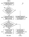
Turning to FIG. 2B, FIG. 2B is a simplified flowchart 200 illustrating one potential operation associated with the present disclosure. In 202, a data packet is communicated to a MER from a UE. For example, UE 12 a may communicate a data packet to MER 50 a. In 204, based on instructions from a GGSN/PGW, the MER determines if the data packet should be offloaded from a default path. If the MER determines that the data packet should not be offloaded, then the data packet can continue along a default path, as illustrated in 206. For example, the data packet may continue along default path 60. If the MER determines that the data packet should be offloaded, then the data packet can be offloaded from the default path, as illustrated in 208. For example, MER 50 may offload the data packet from default path 60 using breakout path 106 and, subsequently, communicate the data packet to Internet 58.
Turning to FIG. 3A, FIG. 3A is a simplified block diagram illustrating one possible set of details associated with communication system 10. FIG. 3A includes handset 12 a, (e)NB 14 a, RNC 32, MER 50 a, SGSN/SGW 34, and GGSN/PGW 54. MER 50 a includes a respective processor 64 a, a traffic offload module 66, and a respective memory element 68 a. GGSN/PGW 54 includes a respective processor 64 b, a MER control module 74, and a respective memory element 68 b. A first upstream tunnel 76 connects RNC 32 to SGSN/SGW 34 through MER 50. A second upstream tunnel 78 connects SGSN/SGW 34 to GGSN/PGW 54. Second upstream tunnel 78 may propagate through a router (e.g., router 52 shown in FIG. 2A) or a MER similar to MER 50 a but located further upstream (for example, if router 52 was configured to be MER 50 b).
In a particular embodiment, MER 50 a is located at the borders between networks/network segments. While MER 50 a may be almost any enhanced network element in communication system 10, the closer that MER 50 a is to UE 12 a, the earlier MER 50 a can offload traffic from default path 60. A first downstream tunnel 80 can connect GGSN/PGW 54 to SGSN/SGW 34. A second downstream tunnel 82 can connect SGSN/SGW 34 to RNC 32 through MER 50 a. Second upstream tunnel 78 and first downstream tunnel 80 may couple through a router (e.g., router 52 shown in FIG. 2A) or a MER similar to MER 50 b shown in FIG. 2A.
GGSN/PGW 54 can use MER control module 74 to control MER 50 a and enable MER 50 a to perform user-plane functions for both packet and circuit mode communication, particularly offloading traffic from the core network (e.g., default path 60). MER 50 a uses traffic offload module to perform the user-plane functions and, further, offload traffic as instructed by GGSN/PGW 54. MER 50 a may also be configured to handle media processing (e.g., speech coding. conference call bridging etc), media generation of tones etc., setup and release of user data bearers, provision of traffic/charging info for packet mode communication, security management, routing and switching QoS management, and element management.
Out-of-band channel 73 is a separate signaling channel established between MER 50 a and GGSN/PGW 54. Out-of-band signaling 72 references communication between MER 50 a and GGSN/PGW 54 that does not occur over default path 60. In-band signaling 70 references communication between MER 50 a and GGSN/PGW 54 (and other elements) using default path 60. In a particular embodiment, the out-of-band signaling 72 association is M:N meaning that any GGSN/PGW 54 may control several MERs, and any MER may be controlled by several GGSNs/PGWs 54. Out-of-band channel 73 is used to establish a GRE tunnel 84 between MER 50 a and GGSN/PGW 54. GRE tunnel 84 is used to loopback traffic to MER 50 a during handovers and discovery procedures and, further, may be used to communicate data to GGSN/PGW 54 that cannot be processed or serviced by MER 50 a. Buffering of user traffic during these procedures can be performed on either GGSN/PGW 54 or MER 50 a or both (implementation dependent).
First upstream tunnel 76, second upstream tunnel 78, first downstream tunnel 80, and second downstream tunnel 82 can be part of default path 60. In addition first upstream tunnel 76, second upstream tunnel 78, first downstream tunnel 80, and second downstream tunnel 82 may be GTP-U tunnels and each may have a unique TEID/source IP address. Initially, MER 50 a does not know the TEID for first upstream tunnel 76, second upstream tunnel 78, first downstream tunnel 80, and second downstream tunnel 82 and, therefore, cannot control UE 12 a's traffic without knowing the TEIDs for first upstream tunnel 76 and second downstream tunnel 82. Using out-of-band channel 73 and TEID discovery procedure, GGSN/PGW 54 communicates the TEID for first upstream tunnel 76 and second downstream tunnel 82 such that MER 50 a knows which UE's traffic is to be controlled and how the UE's traffic should be controlled (e.g., if any traffic from UE 12 a should be offloaded).
GGSN/PGW 54 does not actually know the TEIDs (unless a direct tunnel has been created). Hence, GGSN/PGW 54 relies on MER 50 a to perform TEID discovery and communicate the TEIDs to GGSN/PGW 54 (this may be indirectly through a GTP-U tunneled path). GGSN/PGW 54 in turn, sends a packet back towards MER 50 a thereby enabling download TEID discovery, as well as determining if the upstream TEID (GTP-U tunnel) really was to be off-loaded in the first place (e.g. overlapping IP-addresses could cause a false trigger in the MER). Once TEID discovery is done, GGSN/PGW 54 and MER 50 a can communicate directly (e.g. through GRE tunnel 84) and exchange information about what traffic needs to be off-loaded based on the TEID information exchanged.
Once MER 50 a knows the TEID of first upstream tunnel 76 and second downstream tunnel 82, traffic can be offloaded from default path 60, and when the traffic for UE 12 a is returned, MER 50 a can communicate the data in the returned traffic to UE 12 a. In a particular embodiment, if data is returned to MER 50 a and the returned data needs to propagate through GGSN/PGW 54, then MER 50 a can communicate that data to GGSN/PGW 54 using GRE tunnel 84. GGSN/PGW 54 may similarly return the data to MER 50 a using GRE tunnel 84 or using first downstream tunnel 80.
Turning to FIG. 3B, FIG. 3B is a simplified flowchart 300 illustrating one potential operation associated with the present disclosure. In 302, a data packet can be sent from user equipment requesting a connection to the mobile network. For example, a data packet may be sent from UE 12 a to RNC 32. In 304, GTP-U tunnels are established. For example, first upstream tunnel 76, second upstream tunnel 78, first downstream tunnel 80, and second downstream tunnel 82 may be established. In 306, an out-of-band channel is established between a MER and a GGSN. For example, out-of-band channel 73 may be established between MER 50 a and GGSN/PGW 54. In 308, using the out-of-band channel, the MER can receive data packet offload information from the GGSN. For example, GGSN/PGW 54 may communicate data packet offload information (including TEIDs) to MER 50 a using out of channel band 73.
MER Discovery and Path Selection
Turning to FIG. 4A, FIG. 4A is a simplified block diagram of communication system 10, which (in this particular implementation) may include UE 12 a, cell site 30 a-d, RNCs 32 a-g, MER 50 a-c, SGSN/SGW 34 a-c, and GGSN/PGW 54 a-c. When UE 12 a attaches to the mobile network and requests connection through control plane messages, several GTP-U (user plane) tunnels may be established, (for example, first upstream tunnel 76, second upstream tunnel 78, first downstream tunnel 80, and second downstream tunnel 82 may be established on default path 60). The user plane data packet may propagate through one of cell sites 30 a-d (e.g., cell site 30 d) and through one of RNC 32 a-g (e.g., RNC 32 e). The data packet can travel through first upstream tunnel 76 to MER 50 b. In a particular embodiment, at MER 50 b, a MER identifier is added to a new data packet (in-band message) using the same tunnel identifier as the received user data and the new data packet is communicated to SGSN/SGW 34 b and on to GGSN/PGW 54 a via second upstream tunnel 78. The MER identifier may be an identifier that identifies MER 50 b and informs GGSN/PGW 54 a that MER 50 b is not just a router, but has been enhanced and configured to behave as a MER.
GGSN/PGW 54 a sends a MER discovery message (which can be triggered by the first upstream packet arriving at GGSN/PGW 54 a or immediately after first upstream tunnel 76, second upstream tunnel 78, first downstream tunnel 80, and second downstream tunnel 82 are established) to SGSN/SGW 34 b via first downstream tunnel 80. The MER discovery message travels from SGSN/SGW 34 b to MER 50 b via second downstream tunnel 82. Typically, the message would pass through MER 50 b and onto RNC 32 e; however, MER 50 b intercepts the MER discovery message and establishes out-of-band channel 73 with GGSN/PGW 54 a. By establishing out-of-band channel 73 between MER 50 b and GGSN/PGW 54 a, GGSN/PGW 54 a can control MER 50 b and, further, can communicate offload instructions and other information (such as configuration parameters) for MER 50 b.
While it is possible to manually configure static associations of each MER with RNCs/SGSNs, such a paradigm can be error-prone, lack flexibility, present management issues, and failed to work in many deployment scenarios. In a particular embodiment, each GGSN/PGW 54 a in communication system 10 may be configured to discover which MER in the network is currently forwarding the traffic from/to a specific UE (e.g., UE 12 a), send session control instructions to the discovered MER related to the required treatment of the specific UE's traffic, discover when the specific UE moves from one MER to another (e.g., in a handover scenario), and send control information to the new MER.
In one particular embodiment, a MER identifier is not added to the data packet by MER 50 b. Usage of in-band signaling (not shown) can allow GGSN/PGW 54 a to embed discovery messages in the GTP-U tunnels that were already established for a specific UE. For example, after GGSN/PGW 54 a first receives the data from UE 12 a, GGSN/PGW 54 a can send the discovery message to MER 50 b using first downstream tunnel 80 and second downstream tunnel 82.
Because the discovery message can follow the same path as UE's 12 a traffic, if a MER is present in the path, the MER can always be discovered without prior configurations. No special procedures would be required on other network nodes to pass through such traffic. Interception and interpretation of the embedded messages within these discovery messages can be performed at the MER. Note that such messages are not forwarded to end users (end points) in particular implementations of the present disclosure. Because of the establishment of direct/secure signaling channels between MERs and because control of GGSN/PGWs occurs without prior configurations, the MER discovery procedure is dynamic in nature, does not require manual associations, and operates in a multitude of deployment scenarios.
Dynamic discovery of MER 50 b is enabled by passing IP addresses/ports and protocols, supported by GGSN/PGW 54 a within the in-band discovery message. Further, when UE's 12 a traffic moves from one MER to another MER (e.g., traffic is moved from MER 50 b to MER 50 a), the new MER (MER 50 a) initially forwards such traffic to GGSN/PGW 54 a since it does not yet have instructions from GGSN/PGW 54 a regarding UE's 12 a traffic. Upon receiving the traffic from the new MER (MER 50 a), the GGSN/PGW 54 a is triggered to initiate another MER discovery procedure in which GGSN/PGW 54 a discovers the new MER (MER 50 a) and instructs the new MER to perform the appropriate handling. During the MER discovery procedure, UE's 12 a traffic in the upstream direction, if any, can be buffered at either the new MER or GGSN/PGW 54 a or both (i.e., it can be implementation dependent). The MER discovery procedure can be used in both direct tunnel (DT) and non-DT cases.
Turning to FIG. 4B, FIG. 4B is a simplified flowchart 400 illustrating one potential operation associated with the present disclosure. In 402, a subscriber attaches to a network and requests a connection. For example, a subscriber may use UE 12 a to attach to communication system 10 and request a connection with cell site 30 d. In 404, GPRS-U tunnels are established for the subscriber's traffic. For example, first upstream tunnel 76, second upstream tunnel 78, first downstream tunnel 80, and second downstream tunnel 82 may be established on default path 60 for UE's 12 a traffic. In 406, GGSN sends (to a MER) a discovery message via the GPRS tunnels. For example, GGSN/PGW 54 a may send MER 50 b a discovery message using first downstream tunnel 80, and second downstream tunnel 82.
In 408, the mobile enabled router intercepts the discovery message. For example, MER 50 b may intercept the MER discovery message sent from GGSN/PGW 54 a. In 410, the MER can establish a direct communication channel (out-of-band channel) with the GGSN. For example, MER 50 b may establish out-of-band channel 73 with GGSN/PGW 54 a. In 412, the MER identifies itself to the GGSN, confirms receipt of the discovery request, and obtains session control instructions and other configuration parameters. For example, using out-of-band channel 73, MER 50 b may be configured to identify itself to GGSN/PGW 54 a, confirm receipt of the discovery request, and obtain session control instructions and other configuration parameters from GGSN/PGW 54 a.
TEID Discovery
Turning to FIG. 5A, FIG. 5A is a simplified block diagram of communication system 10, which (in this particular implementation) may include UE 12 a, cell sites 30 a-d, RNCs 32 a-g, MER 50 a-c, SGSN/SGW 34 a-c, and GGSN/PGW 54 a-c. In most deployment scenarios, multiple GTP-U tunnels can be established for the same subscriber's traffic. For example, first upstream tunnel 76 (UL-TEID-1) and second downstream tunnel 82 (DL-TEID-2) can be established between SGSN/SGW 34 b and RNC 32 e, and second upstream tunnel 78 (UL-TEID-3) and first downstream tunnel 80 (DL-TEID-4) can be established between SGSN/SGW 34 b and GGSN/PGW 54 a.
GGSN/PGW 54 a can identify the TEID for second upstream tunnel 78 (UL-TEID-3) and first downstream tunnel 80 (DL-TEID-4). Depending on the scenario, MER 50 b may know only the TEID for first upstream tunnel 76 (UL-TEID-1) and second downstream tunnel 82 (DL-TEID-2), or MER 50 b may not know any TEIDs. Thus, if GGSN/PGW 54 a attempts to instruct MER 50 b about the treatment of UE's 12 a traffic, there is no simple common reference. Furthermore, the inner IP address assigned to UE 12 a is not unique either (i.e., it cannot be used as a common reference), because overlapping IP address support is commonly required. Hence, a TEID discovery procedure needs to be employed to discover the TEID of first upstream tunnel 76 (UL-TEID-1), second downstream tunnel 82 (DL-TEID-2), second upstream tunnel 78 (UL-TEID-3), and first downstream tunnel 80 (DL-TEID-4) and the bindings of these tunnels to UE 12 a.
In a particular embodiment, when a data packet is first sent from UE 12 a through communication system 10, first upstream tunnel 76, second upstream tunnel 78, first downstream tunnel 80, and second downstream tunnel 82 may be established (e.g., on default path 60). The data packet can be communicated to cell site 30 d and to RNC 32 e. Using first upstream tunnel 76, from RNC 32 e, the packet can be communicated to SGSN/SGW 34 b, through MER 50 b. Using second upstream tunnel 78, from SGSN/SGW 34 b, the data packet can also be communicated to GGSN/PGW 54 a.
GGSN/PGW 54 a can receive the data packet and, in response, communicate a MER discovery message to SGSN/SGW 34 b using first downstream tunnel 80. Using the second download link tunnel 82, SGSN/SGW 34 b communicates the MER discovery message to MER 50 b. Typically, the message would pass through MER 50 b and onto RNC 32 e; however, MER 50 b can intercept the MER discovery message and establish out-of-band channel 73 with GGSN/PGW 54 a, if one does not yet exist. By establishing out-of-band channel 73 between MER 50 b and GGSN/PGW 54 a, GGSN/PGW 54 a can control MER 50 b and, further, communicate offload instructions and other information (such as configuration parameters) to MER 50 b.
In order to be able to control the traffic of a specific UE (e.g., UE 12 a), each GGSN/PGW 54 a in communication system 10 can be configured to discover which MER in the network is currently forwarding the traffic from/to that UE (e.g., because GGSN/PGW 54 a received traffic from UE 12 a, and GGSN/PGW 54 a has the intelligence to discover the particular MER that is handling the traffic for UE 12 a). In addition, each GGSN/PGW 54 a in communication system 10 can be configured to send session control instructions to the discovered MER related to the required treatment of the UE's traffic and, further, discover when the UE moves from one MER to another (as in a handover scenario) and subsequently send control information to the new MER.
In a particular embodiment, MER 50 b sends an in-band message (GTP-U packet) in first upstream tunnel 76 in an attempt to discover the associated TEIDs of first upstream tunnel 76 (TEIDs-1-4 bindings in this example). Within the in-band message, UL-TEID-1 is embedded in the payload and the type of message is set to loopback. When the in-band message arrives at SGSN/SGW 34 b, SGSN/SGW 34 b can treat the packet as any other user packet and change the TEID to match the TEID of the second upstream tunnel 78 (TEID-3, in this example), and pass the packet to the appropriate GGSN/PGW 54 a. (Note that the contents of the embedded payload are not necessarily modified by SGSN/SGW 34 b, just the outer tunnel could be modified.)
When the in-band message arrives at GGSN/PGW 54 a, GGSN/PGW 54 a can intercept (i.e., receive) the in-band message and form the requested loopback function based on the embedded message type. If the MER did not include such information in the message, as is applicable to certain deployment cases, GGSN/PGW 54 a may add TEID-3/4 mapping to the payload of an in-band loopback packet (the loopback response to the in-band message) before performing the loopback. GGSN/PGW 54 a can communicate the in-band loopback packet to SGSN/SGW 34 b on first downstream tunnel 80. Using second downstream tunnel 82, SGSN/SGW 34 b can communicate the in-band loopback packet to RNC 32 e.
When the in-band loopback packet arrives at MER 50 b, on the way to RNC 32 e, MER 50 b intercepts and interprets the embedded message, which may include the TEIDs bindings (as well as other parameters, such as the assigned IP address to UE 12 a and GGSN/PGW 54 a). At this juncture, MER 50 b understands which UE's 12 a traffic is to be controlled and is ready to implement whatever policies the GGSN/PGW 54 a may dictate related to traffic from UE 12 a. In one particular embodiment, MER 50 b may also establish out-of-band channel 73 with GGSN/PGW 54 a.
Turning to FIG. 5B, FIG. 5B is a simplified flowchart 500 illustrating one potential operation associated with the present disclosure. In 502, a MER sends an in-band message packet in a tunnel that the MER is attempting to discover. In a particular embodiment, a TEID can be embedded in the payload of the packet, where the message is set to loopback. For example, MER 50 b may send an in-band message packet on first upstream tunnel 76, and the TEID (UL-TEID-1) can be embedded in the payload of the packet. (The message can be embedded in the payload such that a GGSN/PGW would be able to determine the TEID of first upstream tunnel 76.)
In 504, when the packet arrives at an SGSN, the SGSN treats the packet as any other UE packet by changing the TEID and communicating the packet to an appropriate GGSN. (Note that the contents of the embedded payload are not modified by the SGSN, simply the outer tunnel is modified.) For example, SGSN/SGW 34 b may change the outer tunnel TEID from UL-TEID-1 to UL-TEID-3 and communicate the packet to GGSN/PGW 54 a. In 506, when the packet arrives at the GGSN, the GGSN intercepts and interprets the in-band message packet. For example, when the packet arrives at GGSN/PGW 54 a, GGSN/PGW 54 a intercepts and interprets the in-band message packet.
In 508, the GGSN can add TEID bindings (as well as other parameters such as the assigned IP address of the UE) and perform the requested loopback function. In a particular embodiment, the GGSN may add TEID-3/4 mapping to the payload of the message (if the MER did not include such information in the message) before performing the loopback. In 510, the GGSN can communicate the loopback packet to the appropriate SGSN, which forwards it to an appropriate RNC. For example, using first downstream tunnel 80, GGSN/PGW 54 a may communicate the in-band loopback packet to SGSN/SGW 34 b and SGSN/SGW 34 b may communicate the in-band loopback packet to RNC 32 e. In 512, when the loopback packet arrives at the MER (in route to the RNC), the MER intercepts and interprets the embedded message, which may include the TEIDs bindings (as well as other parameters, such as the assigned IP address to the subscriber). At this point, MER 50 b understands which UE's 12 a traffic is to be controlled, and is ready to enforce policies being dictated (e.g., by GGSN/PGW 54 a) for UE's 12 a traffic.
In a particular embodiment, the TEID discovery procedure described above may be repeated when the TEIDs at MER 50 b become stale due to inactivity/timeout, or when TEID conflicts are detected (such as the same TEID is reused by another subscriber after UE 12 a has become dormant). The TEID discovery procedure may not be needed in the case of DT deployments in which just one pair of TEIDs can be used, where both the GGSN/PGW 54 a and MER 50 b identify the same pair. The TEID discovery procedure can be used with non-DT deployments.
Turning to FIG. 6A, FIG. 6A is a simplified block diagram of communication system 10, which (in this particular implementation) includes UE 12 a, cell site 30 a, MER 50 a, MER 50 b, RNC 32, SGSN/SGW 34 a, GGSN/PGW 54 a, and a data transmission network 62. MER 50 a can be in communication with GGSN/PGW 54 a through out-of-band signaling channel 73 a. MER 50 b can be in communication with GGSN/PGW 54 a through out-of-band signaling channel 73 b. In one particular embodiment, data transmission network 62 may include service provider digital subscriber line (DSL) network 114, fiber to the x (FTTx) network 116 (which is a generic term for any broadband network architecture that uses optical fiber in last-mile), Ethernet network 118, and a synchronous optical networking/synchronous digital hierarchy (SONET/SDM) network 120. Each network in data transmission network 62 may have a cost-to-quality ratio, where the cost of using the network is related to the quality of the network.
Data transmission network 62 represents a series of points or nodes of interconnected communication paths for receiving and transmitting packets of information that propagate through communication system 10. Data transmission network 62 offers a communicative interface between sources and/or hosts, and may be any local area network (LAN), wireless local area network (WLAN), metropolitan area network (MAN), Intranet, Extranet, WAN, virtual LAN (VLAN), virtual private network (VPN), or any other appropriate architecture or system that facilitates communications in a network environment. Data transmission network 62 may implement a UDP/IP connection and use a TCP/IP communication language protocol in particular embodiments of the present disclosure. A network can comprise any number of hardware or software elements coupled to (and in communication with) each other through a suitable communications medium. Data transmission network 62 may include the network elements to facilitate data transmission on communication system 10.
Note that DSL network 114, FTTx network 116, Ethernet network 118, and SONET/SDM network 120 may each contain network elements in a particular embodiment of the present disclosure. Each network element may include any suitable hardware, software, components, modules, interfaces, or objects operable to exchange information in a network environment.
In a particular embodiment, certain classes of traffic are defined such that low quality traffic propagates over one network (for example, data may be sent over a low quality network such as DSL network 114) while high quality traffic propagates over another network (for example, a voice call may be sent over a high quality network such as SONET/SDM network 120). Traffic may be sent over a path based on a variety of factors such as a type or level of service purchased by a user, the type of data, the current amount of traffic on a specific network, etc. Because both MER 50 a and MER 50 b should know which type of data should be sent on a network, GGSN/PGW 54 a should send a discovery message to MER 50 a and MER 50 b in order to establish communications with MER 50 a and MER 50 b. The discovery process is similar to the discovery process described above except, both MER 50 a and 50 b should be discovered. When the discovery message reaches MER 50 b, MER 50 b communicates the discovery message to MER 50 a. After receiving the discovery message MER 50 a establishes out-of-band channel 73 a with GGSN/PGW 54 a and MER 50 b establishes out-of-band channel 73 b with GGSN/PGW 54 a and each identifies themselves to GGSN/PGW 54 a.
For example, once a user session has been established using UE 12 a, and traffic for that session is a candidate for selective backhaul link routing, GGSN/PGW 54 a can identify the upstream MER (MER 50 a) and the downstream MER (MER 50 b). To identify MER 50 a and MER 50 b, GGSN/PGW 54 a can use a downstream MER discovery procedure, whereby GGSN/PGW 54 a sends an in-band discovery message towards UE 12 a. The in-band discover message is communicated along default path 60 to MER 50 b (pre-agg/agg router), as well as to MER 50 a (cell site router, provided there is one cell site router per cell site (which is normally the case)).
Both MER 50 a and MER 50 b can identify themselves to GGSN/PGW 54 a and establish out-of- band channels 73 a and 73 b respectively. Out-of-band channel 73 a can be used by GGSN/PGW 54 a to instruct MER 50 a about which upstream traffic should be sent over which link. Out-of-band channel 73 b can be used by GGSN/PGW 54 a to instruct MER 50 b about which downstream traffic should be sent over which link. In addition, in a particular embodiment, MER 50 b is identified, and a GRE tunnel (e.g., GRE tunnel 84 (not shown)) is created between MER 50 b and GGSN/PGW 54 a.
In a particular embodiment, MER 50 a and/or MER 50 b may communicate to GGSN/PGW 54 a about specific links available. GGSN/PGW 54 a can then specify which links to use for particular types of traffic. In another particular embodiment, GGSN/PGW 54 a can simply communicate predefined classes of traffic to MER 50 a and MER 50 b. MER 50 a and/or MER 50 b can then map those classes of traffic to suitable backhaul links available (e.g., “low quality Internet,” “high quality TDM,” etc.).
In one particular embodiment, MER 50 a can establish a backhaul link selection for the upstream traffic. To achieve the backhaul link selection, MER 50 a can perform upstream TEID discovery as described above (except, because end user traffic is not necessarily broken out, but rather just backhauled differently, there is no new IP address and associated NAT bindings being established). [Note that this makes the overall scheme somewhat simpler than a general MER and TEID discovery procedure (including handover), since routing (backhaul) paths can be changed on the fly without affecting an established session (in contrast to the anchor breakout described in the general MER solution).]
Once the signaling described above has been completed, downstream traffic for a particular session may be communicated over different paths by the pre-agg/agg MER (MER 50 b), in accordance with the instructions provided by GGSN/PGW 54 a. Similarly, upstream traffic may be communicated over different upstream paths by the cell site MER (MER 50 a), in accordance with instructions provided by GGSN/PGW 54 a. By routing traffic across an appropriate network, an acceptable cost-to-quality ratio may be achieved for the architecture.
Turning to FIG. 6B, FIG. 6B is a simplified flowchart 600 illustrating one potential operation associated with the present disclosure. In 602, a MER receives network traffic. For example, MER 50 a may receive traffic from cell site 30 a. In 604, the MER can determine which type of traffic was received. In 606, the MER determines which type of network may be used to communicate the traffic and, subsequently, communicates the traffic using the determined network. For example, MER 50 a may determine that the traffic is data traffic and that DSL network 114 can be used to communicate the traffic. MER 50 a may then communicate the traffic over DSL network 114.
Dormant Mode
Turning to FIG. 7A, FIG. 7A is a simplified block diagram of communication system 10, which (in this particular implementation) includes UE 12 a, cell sites 30 a-d, RNCs 32 a-g, MERs 50 a-c, SGSN/SGWs 34 a-c, and GGSN/PGWs 54 a-c. First, upstream tunnel 76 and first downstream tunnel 82 connects RNC 32 e with SGSN/SGW 34 b. Second, upstream tunnel 78 and second downstream tunnel 80 connects SGSN/SGW 34 b with GGSN/PGW 54 a.
Mobile terminals often shift to dormant mode to save power. Note that the term ‘dormant’ as used herein in this Specification encompasses any type of staleness characteristic, timeout, timing parameter expiration, or any other suitable characteristic that would be indicative of some type of dormancy. During dormancy events, the assigned first upstream tunnel 76 and first downstream tunnel 82 between RNC 32 e and SGSN/SGW 34 b can be released. The first upstream tunnel 76 and first downstream tunnel 82 may be reassigned to other subscribers. In certain deployment scenarios, specifically when direct tunneling is employed, GGSN/PGW 54 a can become aware of such events and instruct MER 50 b accordingly. However, in a general deployment case, it is possible that neither GGSN/PGW 54 a nor MER 50 b know that the first upstream tunnel 76 and first downstream tunnel 82 have been released (and possibly reassigned). [Note that second upstream tunnel 78 and second downstream tunnel 80 may stay active during this process.]
Therefore, the MERs (upstream and downstream, if present) may maintain an inactivity timer used to detect potentially stale TEIDs. The inactivity timer may be preset based on the time it would take for an endpoint (and thus a GTP-U tunnel) to be deemed dormant. In addition, the MERs may use a stale state that checks for TEIDs being assigned to another user prior to expiration of the inactivity timer. If the inactivity timer has expired or if a TEID has been assigned to another user (stale state is set), then the discovery procedure can be triggered again to determine the new TEIDs. In a particular embodiment, the downstream tunnel may be identified as dormant based on a stale state setting, for example, due to a GTP-U error indication received from a radio network controller.
Turning to FIG. 7B, FIG. 7B is a simplified block diagram of communication system 10, which (in this particular implementation) includes UE 12 a, RNC 32 e, MER 50 b, SGSN/SGW 34 b, and GGSN/PGW 54 a. In one example, an UE active indicator 96 illustrates that UE 12 a is active. First upstream tunnel 76 and first downstream tunnel 82 connect RNC 32 e with SGSN/SGW 34 b and second upstream tunnel 78 and second downstream tunnel 80 connect SGSN/SGW 34 b with GGSN/PGW 54 a.
In another example, an UE inactive indicator 98 illustrates that UE 12 a is not active and first upstream tunnel 76 and first downstream tunnel 82 have been released. Because the tunnels have been released and are no longer active, MER 50 b is unable to route any data to UE 12 a. If MER 50 b does not receive any data from or destined to UE 12 a during this state, the issue is not a problem. However, if such traffic is received at MER 50 b, then new tunnels should be established for the data to reach UE 12 a. In yet another example, an UE re-active indicator 100 illustrates that UE 12 a has been reactivated and a new first upstream tunnel 86 and a new downstream tunnel 92 have been created.
Using a dormant detection process, where the inactivity timer and the stale state are monitored, MER 50 a is able to determine that first upstream tunnel 76 and second downstream tunnel 82 have been released, and new first upstream tunnel 86 and new second downstream tunnel 92 have been created. If MER 50 a determines that first upstream tunnel 76 and second downstream tunnel 82 have been released, MER 50 a can send an in-band message to GGSN/PGW 54 a to obtain the new association/binding of new first upstream tunnel 86 and new second downstream tunnel 92 through the existing tunnels (tunnels 78 and 80). From GGSN/PGW 54 a, MER 50 b is able to determine the TEID for new first upstream tunnel 86 and new downstream tunnel 92, and route data to/from the user device.
Turning to FIG. 7C, FIG. 7C is a simplified flowchart 700 illustrating one potential operation associated with the present disclosure. (Note that FIG. 7C (due to its length) has been broken into two segments: 7C-1, 7C-2.) In 702, a MER receives a downstream packet. For example, MER 50 a may receive a downstream packet from default path 60, or from breakout path 106 that was created when a packet was offloaded. In 704, the MER determines if network address and port translation (NAPT) binding still exists. If NAPT binding does not still exist, then the packet is dropped, as in 706. If NAPT binding does still exist, then the MER determines if an inactivity timer has expired, as shown in 708. If the inactivity time has expired, then both upstream and downstream tunnels are marked as stale, as shown in 710 and the packet is buffered (depicted in 714). If the inactivity timer has not expired, then the MER determines if the stale state is set, as shown in 712.
If the stale state is not set, then the MER sends the packet to an RNC, as illustrated in 716. In 718, the MER then determines if an error message is received from the RNC (indicating that the downstream tunnel TEID is not correct or no longer valid.) If an error message was not received, then the MER considers the downstream tunnel TEID to be correct. If an error message was received, then both upstream and downstream tunnels are marked as stale, as shown in 710, and the packet is buffered, as depicted in 714. In 720, the MER sends an in-band message to a GGSN/PGW to obtain the identity of the new tunnels. For example, MER 50 a may send an in-band message to GGSN/PGW 54 a using GRE tunnel 84. In 722, the GGSN/PGW sends in-band message towards a SGSN/SGW 34 b using an existing second downstream tunnel, which triggers the SGSN/SGW to start a paging procedure and establish new tunnels to the RNC. For example, GGSN/PGW 54 a may send an in-band message towards SGSN/SGW 34 b using existing second downstream tunnel 80, which triggers SGSN/SGW 34 b to start a paging procedure and establish new tunnels (86 and 92) to RNC 32 e. In 724, the MER receives a MER discovery message from the GGSN that includes the TEID of the new upstream and downstream tunnels. In 726, using the TEID of the new tunnels, the buffer is drained and the packet is sent to the RNC.
IP Routing
Turning to FIG. 8A, FIG. 8A is a simplified block diagram of communication system 10, which (in this particular implementation) includes UE 12 a, cell sites 30 a-c, RNC 32, MER 50 a-c, SGSN/SGW 34, GGSN/PGW 54, first upstream tunnel 76, second upstream tunnel 78, first downstream tunnel 80, second downstream tunnel 82, out-of-band channel 73, GRE tunnel 84, core network 56, and Internet 58. FIG. 8A further includes an IP point of attachment 124.
In accordance with one example implementation, packets from UE 12 a are communicated to MER 50 a. Based on instructions from GGSN/PGW 54, MER 50 a determines which traffic to offload, where it uses IP-based routing to act as an anchor point. The offloaded traffic 108 is communicated on breakout path 106. Use of IP-based routing, allows for mid-flow breakout of traffic and also avoids NAT-ing at MER 50 a. MER 50 a can act as an upstream router instead of incurring the cost of the mobile plane, as the routing offload point is where the subscriber is hosted and MER 50 a acts as the upstream point to external networks (such as Internet 58).
Data can be routed from its source to its destination through a series of routers, and across multiple networks. IP Routing is an umbrella term for the set of protocols that determine the path that data follows in order to travel across multiple networks from its source to its destination. The IP Routing protocols enable MERs 50 and routers 52 to build up a forwarding table that correlates final destinations with next hop addresses. These protocols can include Border Gateway Protocol (BGP), Intermediate System-Intermediate System (IS-IS), Open Shortest Path First (OSPF), Routing Information Protocol (RIP), etc. When an IP packet is to be forwarded, a router uses its forwarding table to determine the next hop for the packet's destination (based on the destination IP address in the IP packet header), and forwards the packet appropriately. The next router then repeats this process using its own forwarding table, and so on until the packet reaches its destination. At each stage, the IP address in the packet header is sufficient information to determine the next hop; no additional protocol headers are required.
In a particular embodiment, MER 50 a assigns IP addresses to each traffic flow for which MER 50 a serves as the anchor router. In a particular embodiment, a range of IP addresses that are the last hop for MER 50 a or GGSN/PGW 54 (which can be configured at different regularities) are assigned to each traffic flow. In another particular embodiment, IP addresses are dynamically distributed between MER 50 a and GGSN/PGW 54. The assigned IP address allows for traffic to be returned to either MER 50 a or GGSN/PGW 54.
In a particular embodiment, traffic is de-capsulated at MER 50 a. MER 50 a can determine if a de-capsulated packet matches an inner IP access control list, a TEID, or both. For example, for global ACL configurations for PDPs, inner destination IP address is not at the provider content network (i.e., traffic is toward distributed or Internet content), and for per-PDP ACL, a 5-tuple match for inner IP flow of a PDP context. Further packet analysis on the gateway can be used to determine IP flows of the default bearer, and the secondary PDP/dedicated bearer is set for breakout. If the packet does match, then an IP address can be assigned to the packet such that MER 50 a would serve as the anchor or host router. If the packet does not match, then the packet can be communicated to SGSN/SGW 34.
In accordance with one example implementation, MER 50 a can receive downstream traffic from Internet 58 and also communicate the traffic to UE 12 a. In another example implementation, MER 50 a receives downstream traffic from Internet 58; however, based on the type of traffic, services should be applied to the packet flow and MER 50 a is not necessarily capable of performing those services. In this case, the operator serviced traffic 122 that needs the services applied (such as transactions or charging (e.g., Layer 7 billing), firewall capabilities, etc.) can be communicated to GGSN/PGW 54 using GRE tunnel 84. In a particular embodiment, the operator-serviced traffic 122 cannot be serviced by GGSN/PGW 54 and the operator-serviced traffic 122 is offloaded to core network 56 for servicing. In this manner, downstream traffic is received by MER 50 a and, if further or special services are needed, operator serviced traffic 122 is communicated from MER 50 a to GGSN/PGW 54 (using GRE tunnel 84 such that the traffic is offloaded to core network 56). MER 50 a may be capable of performing some services depending on the number of data plane levels available on MER 50 a.
Turning to FIG. 8B, FIG. 8B is a simplified flowchart 800 illustrating one potential operation associated with the present disclosure. In 802, traffic is received at a MER. For example, upstream or downstream traffic may be received at MER 50 a. In 804, the MER can determine if the traffic is GTP-U encapsulated. If the traffic is not GTP-U encapsulated, then the MER can determine if the traffic is mobile traffic, at 806. If the traffic is not mobile traffic, then standard routing functions are performed, at 808. If the traffic is mobile traffic, then the functions as specified by a MER-CA are performed on the traffic, at 810. If the traffic is GTP-U encapsulated, then the MER can determine if the traffic is upstream traffic or downstream traffic, at 812.
If the traffic is downstream traffic, the MER can determine if it is expecting to receive traffic from the GGSN on the TEID and inner IP, at 814. If traffic is not expected from the GGSN on the TEID and inner IP, then the TEID is marked as stale and rediscovery is initiated, at 816. If the MER is expecting to receive traffic from the GGSN on the TEID and inner IP, then the packet is communicated to a RNC or an eNode B by the MER, at 818.
If the traffic is upstream traffic, then the MER de-capsulates the packet, and can determine if the de-capsulated packet matches an inner IP access control list, a TEID, or both, as shown in 820. If the MER determines that the de-capsulated packet does match an inner IP access control list, a TEID, or both, then an IP address is assigned to the de-capsulated packet and the de-capsulated packet is broken out, as shown in 822. If the MER determines that the de-capsulated packet does not match an inner IP access control list, a TEID, or both, then the de-capsulated packet is communicated on to a GGSN, as shown in 824. For example, using GRE tunnel 84, MER 50 a may communicate to GGSN/PGW 34, a de-capsulated packet that needs a service performed.
Turning to FIG. 8C, FIG. 8C is a simplified block diagram of communication system 10, which (in this particular implementation) includes UE 12 a, cell sites 30 a-c, RNC 32, MER 50 a-c, SGSN/SGW 34, GGSN/PGW 54, first upstream tunnel 76, second upstream tunnel 78, first downstream tunnel 80, second downstream tunnel 82, out-of-band channel 73, GRE tunnel 84, core network 56, and Internet 58. FIG. 8C may also include an embedded NAT 110. FIG. 8C is similar to FIG. 8A except for the addition of embedded NAT 110. When a packet in the traffic flow needs extra processing outside GGSN/PGW 54 (CDR generation, complex CDRS, voice) and those packets still have the source IP address originally assigned by MER 50 a. The addition of embedded NAT 110 can help facilitate the extra processing and ensure the traffic is returned to GGSN/PGW 54.
NAT-ing is the process of modifying IP address information in the IP packet header of the packet in the traffic flow, while the packet is in transit across MER 50 a. The simplest type of NAT provides a one-to-one translation of IP addresses (e.g., basic NAT or one-to-one NAT). In this type of NAT, the IP addresses, IP header checksum, and/or any higher-level checksums (that include the IP address) are changed. The rest of the packet can be left untouched (at least for basic TCP/UDP functionality, some higher-level protocols may need further translation).
Basic NATs can be used when there is a requirement to interconnect two IP networks with incompatible addressing. However, it is common to hide an entire IP address space, usually consisting of private IP addresses, behind a single IP address (or in some cases a small group of IP addresses) in another (usually public) address space. To avoid ambiguity in the handling of returned packets, a one-to-many NAT should alter higher-level information such as TCP/UDP ports in outgoing communications and, further, should maintain a translation table so that return packets can be correctly translated back. (e.g., NAPT or port address translation (PAT), IP masquerading, NAT Overload, etc.).
In accordance with one example implementation described in FIG. 8A, downstream traffic ended up at MER 50 a and MER 50 a determined whether or not the traffic could be communicated to UE 12 a, or if the traffic needed to shift to GGSN/PGW 54 for services. When flows are not being offloaded (or flow through the GRE tunnel), and have services applied, in order to return the downstream packets for a user (for a non-broken out flow) NAT 110 assigns the user a different IP address. For example, some complex services can be applied at GGSN/PGW 54 using core network 56.
The upstream traffic with the complex services is communicated to GGSN/PGW 54 and is NAT-ed before it is communicated to core network 56 so the traffic will return to GGSN/PGW 54. Otherwise, the traffic can be offloaded, FIG. 8A, and the source address of the upstream is still the one that was assigned to the user. If the traffic is not uploaded, it still has the source address of the user. Hence, NAT 110 assigns a different IP address before the traffic is sent to core network 56. That new source address allows the packet to return back to the GGSN/PGW 54 and not MER 50 a.
Turning to FIG. 8D, FIG. 8D is a simplified flowchart 801 illustrating one potential operation associated with the present disclosure. In 822, upstream traffic is received at a MER and is de-capsulated. The MER determines if a de-capsulated packet matches an inner IP access control list, a TEID, or both, as in 824. If the MER determines that the de-capsulated packet matches an inner IP access control list, a TEID, or both, then an IP address is assigned to the de-capsulated packet and the de-capsulated packet is broken out, as in 826. If the MER determines that the de-capsulated packet does not match an inner IP access control list, a TEID, or both, then the de-capsulated packet is communicated on to an SGSN/SGW, as in 828. In 830, the GGSN/PGW determines if a service should be performed on the de-capsulated packet that cannot be performed by the GGSN/PGW. If the GGSN/PGW determines that the service cannot be performed by the GGSN/PGW, then NAT binding is attached to the de-capsulated packet and the de-capsulated packed is sent for processing, as in 834. If the GGSN/PGW determines that the service can be performed by the GGSN/PGW, then the GGSN/PGW can perform the service on the de-capsulated packet, as in 832.
NAT Routing
Turning to FIG. 9A, FIG. 9A is a simplified block diagram of communication system 10, which (in this particular implementation) includes UE 12 a, cell sites 30 a-c, RNC 32, MER 50 a, routers 52, SGSN/SGW 34, GGSN/PGW 54, first upstream tunnel 76, second upstream tunnel 78, first downstream tunnel 80, second downstream tunnel 82, out-of-band channel 73, GRE tunnel 84, core network 56, embedded NAT 110, IP point of attachment 124, and Internet 58.
In accordance with one example implementation, packets from UE 12 a are communicated to MER 50 a. MER 50 a determines which traffic to offload and uses embedded NAT 110 to act as an anchor point. Use of NAT allows for a mid-flow breakout of traffic and does not require MER 50 a to be an anchor point. For example, if UE 12 a is mobile, MER may be moved to a new MER and the new MER could become the new anchor MER. MER 50 a acts as the upstream point of attach to external networks (such as Internet 58). When the anchor point moves to the new MER, the IP session may be kept. In a particular embodiment, a tunnel is established between the anchor MER and the new MER to provide a mobile support.
In a particular embodiment, traffic is de-capsulated at MER 50 a. MER 50 a determines if a de-capsulated packet matches an inner IP access control list, a TEID, or both. (For example, if global configurations ACL for PDPs: inner destination IP address is not at provider content network (i.e., traffic is toward distributed or Internet content), per-PDP ACL: 5-tuple match for inner IP flow of a PDP context. DPI on GW is used to determine IP flows of PDP context, and entire secondary PDP/dedicated bearer is set for breakout.) If the packet does match, then the inner IP of the packet is NAT-ed such that MER 50 a will be the anchor router. If the packet does not match, then the packet is communicated to SGSN/SGW 34. Because the packet is NAT-ed, the anchor point for the offloaded packet is MER 50 a. MER 50 a receives the offloaded packet as downstream traffic from Internet 58 and communicates the packet to UE 12 a. In a particular embodiment, MER 50 a determines if services should be applied to the offloaded packet. If services are necessary, then the offloaded packet may be NAT-ed such that the offloaded packet will return to GGSN/PGW 54 where the services can be applied. Hence, the packet would not be returned to MER 50 a and then tunneled back to GGSN/PGW 54, the packet would go directly to GGSN/PGW 54.
Turning to FIG. 9B, FIG. 9B is a simplified flowchart 900 illustrating one potential operation associated with the present disclosure. In 902, traffic is received at a MER. In 904, the MER determines if the traffic is upstream traffic or downstream traffic. If the traffic is downstream traffic, based on the NAT binding of the downstream traffic, the GTP tunnel header and TEID are restored by the MER and the MER can perform any general packet radio service tunneling protocol sequencing, as in 906. In 908, the downstream traffic is communicated to a RNC.
If the traffic is upstream traffic, the MER determines if a packet matches an inner IP access control list, a TEID, or both, as in 910. If the MER determines that the packet does not match, then the packet is communicated on to an SGSN/SGW, as in 912. For example, if MER 50 a determines that the packet does not match, then the packet is communicated on to an SGSN/SGW 34. If the MER determines that the packet does match, then the packet is de-capsulated and the de-capsulated packet is NAT-ed and broken out, as shown in 914.
Turning to FIG. 9C, FIG. 9C is a simplified block diagram of communication system 10, which (in this particular implementation) includes UE 12 a, cell sites 30 a-c, RNC 32, MER 50 a, routers 52, SGSN/SGW 34, GGSN/PGW 54, first upstream tunnel 76, second upstream tunnel 78, first downstream tunnel 80, second downstream tunnel 82, out-of-band channel 73, GRE tunnel 84, core network 56, carrier grade NAT (CGN) 112, IP point of attachment 124, and Internet 58. In accordance with one example implementation, packets from UE 12 a are communicated to MER 50 a. MER 50 a determines which traffic to offload and uses carrier grade NAT (CGN) 112 to act as an anchor point.
CGN (sometimes referred to as large-scale NAT (LSN)), is an approach to IPv4 network design where end sites (for example homes) are not given public IPv4 addresses. Instead, the end sites are given private addresses that are translated to public by middleboxes embedded in a network operator's network. This allows the network operator to share a common pool or pools of addresses among several end sites. CGN can also be used for IPv6 as well as translation between IPv4 and IPv6.
Asymmetric Routing
Turning to FIG. 10A, FIG. 10A is a simplified block diagram of a portion of communication system 10 depicting one example of an asymmetric routing 102 a. Asymmetric routing 102 a can include RNC 32, MER 50 a, MER 50 b, and SGSN/SGW 34. In this example, link 126 connects RNC 32 with MER 50 a, link 128 connects RNC 32 with MER 50 b, link 130 connects MER 50 a with SGSN/SGW 34, and link 132 connects MER 50 b with SGSN/SGW 34.
In some deployments, routers or MERs may be configured to operate in an active/active mode instead of active/standby mode. For example, MER 50 a and MER 50 b may be configured to operate in an active/active mode where both are active. In this case, UE's traffic may be loadbalanced between MER 50 a and MER 50 b without UE's awareness. As a result, traffic from one UE may traverse through different routers (or MERs) and the control of such traffic becomes more challenging. In one particular embodiment, policy based routing (PBR) may be used to bring mobile-related traffic to one MER for service enforcement. The service enforcement is in active/standby mode while the routers are in active/active mode. In another particular embodiment, a new function to MER is added such that the service enforcement forwards mobile traffic of specific subscribers to peers responsible for the control of such subscribers.
FIG. 10B is a simplified schematic diagram illustrating possible examples of a link (e.g., link 126 or link 130) to MER 50 a becoming disabled. For example, 102 b depicts link 126 becoming disabled (e.g., due to a loss of connection between RNC 32 and MER 50 a). In a particular embodiment, PBR is used to reroute traffic 104 a (that was communicated from MER 50 a to RNC 32 over link 126) from MER 50 b to RNC 32 (over link 128). Because link 130 is still active and not disabled, traffic 104 c continues to flow from/to MER 50 a to/from SGSN/SGW 34 over link 130.
In a similar example, 102 c depicts link 130 becoming disabled (e.g., due to a loss of connection between MER 50 a and SGSN/SGW 34). In a particular embodiment, PBR is used to reroute traffic 104 c (that was communicated from MER 50 a to SGSN/SGW 34 over link 130) from MER 50 b to SGSN/SGW 34 over link 132. Because link 126 is still active and not disabled, traffic 104 a continues to flow from/to MER 50 a to/from RNC 32 over link 126.
FIG. 10C is a simplified schematic diagram illustrating possible examples of a link (e.g., link 128 or link 132) to MER 50 b becoming disabled. For example, 102 d depicts link 128 becoming disabled (e.g., due to a loss of connection between RNC 32 and MER 50 b). In a particular embodiment, PBR is used to reroute traffic 104 b (that was communicated from MER 50 b to RNC 32 over link 128) from MER 50 a to RNC 32 (over link 126). Because link 132 is still active and not disabled, traffic 104 d continues to flow from/to MER 50 b to/from SGSN/SGW 34 over link 132.
In a similar example, 102 e depicts link 132 becoming disabled (e.g., due to a loss of connection between MER 50 b and SGSN/SGW 34). In a particular embodiment, PBR is used to reroute traffic 104 d (that was communicated from MER 50 b to SGSN/SGW 34 over link 132) from MER 50 a to SGSN/SGW 34 over link 130. Because link 128 is still active and not disabled, traffic 104 b continues to flow from/to MER 50 b to/from RNC 32 over link 128.
FIG. 10D is a simplified schematic diagram illustrating two possible examples of a MER (e.g., MER 50 a or MER 50 b) becoming disabled. For example, 102 f depicts MER 50 b becoming disabled (e.g., due to a mechanical failure of MER 50 b). In a particular embodiment, PBR can be used to reroute traffic 104 b that was communicated from MER 50 b to RNC 32 over link 128, and to reroute traffic 104 d that was communicated from MER 50 b to SGSN/SGW 34 over link 132. Because links 126 and 130 are still active and not disabled, traffic can be communicated from MER 50 a to RNC 32 over link 126, and to SGSN/SGW 34 over link 130.
In a similar example, 102 g illustrates a scenario in which MER 50 a has become disabled (e.g., due to a mechanical failure of MER 50 a). In a particular embodiment, PBR can be used to reroute traffic 104 a that was communicated from MER 50 a to RNC 32 over link 126, and reroute traffic 104 c that was communicated from MER 50 b to SGSN/SGW 34 over link 130. Because links 128 and 132 are still active and not disabled, traffic can be communicated from MER 50 b to RNC 32 over link 128, and to SGSN/SGW 34 over link 132.
FIG. 10E is a simplified schematic diagram illustrating an example of when link 130 has become disabled (e.g., due to a loss of connection between MER 50 a and SGSN/SGW 34) and the link failure does not trigger a MER switchover. As shown in the example, traffic 104 a, 104 b, 104 c, and 104 d should first propagate through MER 50 a and then be rerouted through MER 50 b. As a result, inter-chassis traffic becomes extreme (i.e., may require additional physical links to be installed on both routers).
FIG. 10F is a simplified schematic diagram illustrating a graphical example of when link 130 has become disabled (e.g., due to a loss of connection between MER 50 a and SGSN/SGW 34), and the link failure triggers a MER switchover. As shown in the example, traffic 104 b, 104 c, and 104 d does not first propagate through MER 50 a and then be rerouted through MER 50 b. Instead, traffic 104 a is routed from MER 50 b to MER 50 a. As a result, inter-chassis traffic does not becomes extreme (i.e., does not require additional physical links to be installed on both routers). In order to achieve the re-routing of traffic, certain link failures may trigger MER switchover based on configured policies and available inter-chassis bandwidth
Turning to FIG. 11, FIG. 11 is a simplified block diagram of an in-band signaling packet 134. In-band signaling packet 134 may include an outer tunnel IP header 136, an inner packet IP header 138, and a payload 140. Fields 102 and fields 142 (or a subset) indicate parameters that can be configured by MER 50 a and/or a MER-CA (e.g., GGSN/PGW 54). Fields 144 (or a subset) indicate parameters that should be used without modifications.
Payload 140 may contain in-band protocol data elements. For example, payload 140 may contain the type of message, the IP assigned to UE (e.g., UE 12 a), downstream and upstream TEIDs, packet hashes, MER CA and MER Control Plane/Data Plane (CP/DP) address/port to be used, MER and MER CA ID, and future extensions, which can include other elements. The message type may be a MER discovery message, a TEID discovery/loopback, an end-marker, a paging trigger, or future extensions.
Note that in certain example implementations, the data communication and routing functions outlined herein may be implemented by logic encoded in one or more tangible media (e.g., embedded logic provided in an application specific integrated circuit [ASIC], network processors, digital signal processor [DSP] instructions, software [potentially inclusive of object code and source code] to be executed by a processor, or other similar machine, etc.). In some of these instances, a memory element [as shown in FIG. 3A] can store data used for the operations described herein. This includes the memory element being able to store software, logic, code, or processor instructions that are executed to carry out the activities described in this Specification.
A processor can execute any type of instructions associated with the data to achieve the operations detailed herein in this Specification. In one example, the processor [as shown in FIG. 3A] could transform an element or an article (e.g., data) from one state or thing to another state or thing. In another example, the data communication and routing activities outlined herein may be implemented with fixed logic or programmable logic (e.g., software/computer instructions executed by a processor) and the elements identified herein could be some type of a programmable processor, programmable digital logic (e.g., a field programmable gate array [FPGA], an erasable programmable read only memory (EPROM), an electrically erasable programmable ROM (EEPROM)) or an ASIC that includes digital logic, software, code, electronic instructions, or any suitable combination thereof.
In one example implementation, MER 50 a and/or MER-CA (e.g., GGSN/PGW 54) may include software (e.g., provisioned as traffic offload module 66, MER control module 74, etc.) in order to achieve the data communication functions outlined herein. These devices may further keep information in any suitable memory element [random access memory (RAM), ROM, EPROM, EEPROM, ASIC, etc.], software, hardware, or in any other suitable component, device, element, or object where appropriate and based on particular needs. Any of the memory items discussed herein (e.g., database, tables, trees, queues, caches, etc.) should be construed as being encompassed within the broad term ‘memory element.’ Similarly, any of the potential processing elements, modules, and machines described in this Specification should be construed as being encompassed within the broad term ‘processor.’ Each of these elements (e.g., MER 50 a and MER-CA (e.g., GGSN/PGW 54)) can also include suitable interfaces for receiving, transmitting, and/or otherwise communicating data or information in a network environment.
MER 50 a and MER-CA (e.g., GGSN/PGW 54) are network elements configured to perform the traffic offloading activities disclosed herein. As used herein in this Specification, the term ‘network element’ may include any suitable hardware, software, components, modules, interfaces, or objects operable to exchange information in a network environment. Further, the term network element as discussed herein encompasses (but is not limited to) devices such as routers, switches, gateways, bridges, loadbalancers, firewalls, inline service nodes, proxies, clients, servers processors, modules, or any other suitable device, component, element, proprietary device, network appliance, or object operable to exchange information in a network environment. This may be inclusive of appropriate algorithms and communication protocols that allow for the effective exchange of data or information.
Note that with the example provided above, as well as numerous other examples provided herein, interaction may be described in terms of two, three, or four network elements. However, this has been done for purposes of clarity and example only. In certain cases, it may be easier to describe one or more of the functionalities of a given set of flows by only referencing a limited number of network elements. It should be appreciated that communication system 10 (and its teachings) are readily scalable and can accommodate a large number of components, as well as more complicated/sophisticated arrangements and configurations. Accordingly, the examples provided should not limit the scope or inhibit the broad teachings of communication system 10 as potentially applied to a myriad of other architectures.
It is also important to note that the steps in the preceding flow diagrams illustrate only some of the possible scenarios and patterns that may be executed by, or within, communication system 10. Some of these steps may be deleted or removed where appropriate, or these steps may be modified or changed considerably without departing from the scope of the present disclosure. In addition, a number of these operations may have been described as being executed concurrently with, or in parallel to, one or more additional operations. However, the timing of these operations may be altered considerably. The preceding operational flows have been offered for purposes of example and discussion. Substantial flexibility is provided by communication system 10 in that any suitable arrangements, chronologies, configurations, and timing mechanisms may be provided without departing from the teachings of the present disclosure.
Numerous other changes, substitutions, variations, alterations, and modifications may be ascertained to one skilled in the art and it is intended that the present disclosure encompass all such changes, substitutions, variations, alterations, and modifications as falling within the scope of the appended claims. It is also imperative to note that the architecture outlined herein can be used in different types of network applications. The architecture of the present disclosure can readily be used such environments, as the teachings of the present disclosure are equally applicable to all such alternatives and permutations.
In order to assist the United States Patent and Trademark Office (USPTO) and, additionally, any readers of any patent issued on this application in interpreting the claims appended hereto, Applicant wishes to note that the Applicant: (a) does not intend any of the appended claims to invoke paragraph six (6) of 35 U.S.C. section 112 as it exists on the date of the filing hereof unless the words “means for” or “step for” are specifically used in the particular claims; and (b) does not intend, by any statement in the specification, to limit this disclosure in any way that is not otherwise reflected in the appended claims.

Claims (15)

What is claimed is:
1. A method, comprising:
receiving a data packet over a first link at a first network element;
transmitting from the first network element a tunnel endpoint identifier of the first link over the first link;
receiving a discovery message over a second link, the discovery message including a tunnel endpoint identifier of the second link, the discovery message triggering an establishment of an out-of-band channel;
establishing the out-of-band channel over a third link between the first network element and a second network element;
establishing a generic routing encapsulation (GRE) tunnel between the first network element and the second network element using the out-of-band channel; and
receiving instructions at the first network element over the third link to offload the data packet from the first link, wherein the first network element is configured to use the out-of-band channel to identify the first network element to the second network element, to confirm a receipt of the discovery message, and to obtain the instructions.
2. The method of claim 1, wherein the first network element is a mobile enabled router, and the second network element is a gateway general packet radio service support node or a packet data network gateway.
3. The method of claim 1, wherein the data packet is offloaded based on whether data in the data packet is voice data.
4. The method of claim 1, wherein the first network element is configured to map classes of traffic to backhaul links based on a level of quality of the traffic.
5. The method of claim 1, wherein the GRE tunnel is used to loopback traffic to the first network element during handover activities.
6. Logic encoded in one or more non-transitory media that includes code for execution and, when executed by a processor, is operable to perform operations comprising:
receiving a data packet over a first link at a first network element;
transmitting from the first network element a tunnel endpoint identifier of the first link over the first link;
receiving a discovery message over a second link, the discovery message including a tunnel endpoint identifier of the second link, the discovery message triggering an establishment of an out-of-band channel;
establishing the out-of-band channel over a third link between the first network element and a second network element;
establishing a generic routing encapsulation (GRE) tunnel between the first network element and the second network element using the out-of-band channel;
receiving instructions at the first network element over the third link to offload the data packet from the first link; and
using the out-of-band channel to identify the first network element to the second network element, to confirm a receipt of the discovery message, and to obtain the instructions.
7. The logic of claim 6, wherein the first network element is a mobile enabled router, and the second network element is a gateway general packet radio service support node or a packet data network gateway.
8. The logic of claim 6, wherein the data packet is offloaded based on whether data in the data packet is voice data.
9. The logic of claim 6, the operations further comprising:
mapping classes of traffic to backhaul links based on a level of quality of the traffic.
10. The logic of claim 6, wherein the GRE tunnel is used to loopback traffic to the first network element during handover activities.
11. An apparatus, comprising:
a memory element configured to store data; and
a processor operable to execute instructions associated with the data;
wherein the apparatus is configured to
receive a data packet over a first link;
transmit from the apparatus a tunnel endpoint identifier of the first link over the first link;
receive a discovery message over a second link, the discovery message including a tunnel endpoint identifier of the second link, the discovery message triggering an establishment of an out-of-band channel;
establish the out-of-band channel over a third link with a network element;
establish a generic routing encapsulation (GRE) tunnel between the apparatus and the network element using the out-of-band channel; and
receive instructions over the third link to offload the data packet from the first link, wherein the apparatus is configured to use the out-of-band channel to identify the apparatus to the network element, to confirm a receipt of the discovery message, and to obtain the instructions.
12. The apparatus of claim 11, wherein the data packet is offloaded based on whether data in the data packet is voice data, and the apparatus is configured to map classes of traffic to backhaul links based on a level of quality of the traffic.
13. The method of claim 1, wherein the receiving the discovery message is performed when the first network element transmits a packet over the first link or when the second link is established.
14. The logic of claim 6, wherein the receiving the discovery message is performed when the first network element transmits a packet over the first link or when the second link is established.
15. The apparatus of claim 11, wherein the apparatus receives the discovery message when the apparatus transmits a packet over the first link or when the second link is established.
US13/179,538 2010-10-05 2011-07-10 System and method for offloading data in a communication system Active US9031038B2 (en)

Priority Applications (1)

Application Number Priority Date Filing Date Title
US13/179,538 US9031038B2 (en) 2010-10-05 2011-07-10 System and method for offloading data in a communication system

Applications Claiming Priority (2)

Application Number Priority Date Filing Date Title
US38997110P 2010-10-05 2010-10-05
US13/179,538 US9031038B2 (en) 2010-10-05 2011-07-10 System and method for offloading data in a communication system

Publications (2)

Publication Number Publication Date
US20120082132A1 US20120082132A1 (en) 2012-04-05
US9031038B2 true US9031038B2 (en) 2015-05-12

Family

ID=45889766

Family Applications (8)

Application Number Title Priority Date Filing Date
US13/112,581 Active 2032-10-26 US8787303B2 (en) 2010-10-05 2011-05-20 Methods and apparatus for data traffic offloading at a router
US13/179,538 Active US9031038B2 (en) 2010-10-05 2011-07-10 System and method for offloading data in a communication system
US13/179,542 Active 2031-09-08 US8897183B2 (en) 2010-10-05 2011-07-10 System and method for offloading data in a communication system
US13/179,540 Active US9030991B2 (en) 2010-10-05 2011-07-10 System and method for offloading data in a communication system
US13/179,539 Active US9049046B2 (en) 2010-07-16 2011-07-10 System and method for offloading data in a communication system
US13/179,541 Active 2031-07-28 US9014158B2 (en) 2010-10-05 2011-07-10 System and method for offloading data in a communication system
US14/683,228 Active 2031-12-30 US9973961B2 (en) 2010-10-05 2015-04-10 System and method for offloading data in a communication system
US15/978,694 Active US10588044B2 (en) 2010-10-05 2018-05-14 System and method for offloading data in a communication system

Family Applications Before (1)

Application Number Title Priority Date Filing Date
US13/112,581 Active 2032-10-26 US8787303B2 (en) 2010-10-05 2011-05-20 Methods and apparatus for data traffic offloading at a router

Family Applications After (6)

Application Number Title Priority Date Filing Date
US13/179,542 Active 2031-09-08 US8897183B2 (en) 2010-10-05 2011-07-10 System and method for offloading data in a communication system
US13/179,540 Active US9030991B2 (en) 2010-10-05 2011-07-10 System and method for offloading data in a communication system
US13/179,539 Active US9049046B2 (en) 2010-07-16 2011-07-10 System and method for offloading data in a communication system
US13/179,541 Active 2031-07-28 US9014158B2 (en) 2010-10-05 2011-07-10 System and method for offloading data in a communication system
US14/683,228 Active 2031-12-30 US9973961B2 (en) 2010-10-05 2015-04-10 System and method for offloading data in a communication system
US15/978,694 Active US10588044B2 (en) 2010-10-05 2018-05-14 System and method for offloading data in a communication system

Country Status (1)

Country Link
US (8) US8787303B2 (en)

Cited By (8)

* Cited by examiner, † Cited by third party
Publication number Priority date Publication date Assignee Title
US9210122B2 (en) 2009-11-18 2015-12-08 Cisco Technology, Inc. System and method for inspecting domain name system flows in a network environment
US9246837B2 (en) 2009-12-19 2016-01-26 Cisco Technology, Inc. System and method for managing out of order packets in a network environment
US9246825B2 (en) 2011-06-14 2016-01-26 Cisco Technology, Inc. Accelerated processing of aggregate data flows in a network environment
US9722933B2 (en) 2011-06-14 2017-08-01 Cisco Technology, Inc. Selective packet sequence acceleration in a network environment
US9825870B2 (en) 2009-11-18 2017-11-21 Cisco Technology, Inc. System and method for reporting packet characteristics in a network environment
US9973961B2 (en) 2010-10-05 2018-05-15 Cisco Technology, Inc. System and method for offloading data in a communication system
US10110433B2 (en) 2011-01-04 2018-10-23 Cisco Technology, Inc. System and method for exchanging information in a mobile wireless network environment
US11464077B1 (en) 2020-07-10 2022-10-04 Sprint Communications Company L.P. Wireless access node usage based on packet drop rate

Families Citing this family (149)

* Cited by examiner, † Cited by third party
Publication number Priority date Publication date Assignee Title
US8081642B2 (en) * 2003-01-31 2011-12-20 Brocade Communications Systems, Inc. Method and apparatus for routing between fibre channel fabrics
US9148380B2 (en) * 2009-11-23 2015-09-29 Cisco Technology, Inc. System and method for providing a sequence numbering mechanism in a network environment
FR2968155A1 (en) * 2010-11-30 2012-06-01 France Telecom COMMUNICATION TECHNIQUE BETWEEN USER EQUIPMENT AND A DATA NETWORK IN A COMMUNICATION NETWORK
FR2968156A1 (en) 2010-11-30 2012-06-01 France Telecom COMMUNICATION TECHNIQUE BETWEEN USER EQUIPMENT AND A DATA NETWORK IN A COMMUNICATION NETWORK
EP2501163A1 (en) * 2011-03-18 2012-09-19 Alcatel Lucent Traffic offload in a multi-access mobile communication system supporting network-based IP mobility
US8792353B1 (en) 2011-06-14 2014-07-29 Cisco Technology, Inc. Preserving sequencing during selective packet acceleration in a network environment
US8743690B1 (en) 2011-06-14 2014-06-03 Cisco Technology, Inc. Selective packet sequence acceleration in a network environment
US20130007286A1 (en) * 2011-06-29 2013-01-03 Juniper Networks, Inc. User session routing between mobile network gateways
US8650279B2 (en) 2011-06-29 2014-02-11 Juniper Networks, Inc. Mobile gateway having decentralized control plane for anchoring subscriber sessions
EP2727431B1 (en) * 2011-07-01 2015-07-01 Telefonaktiebolaget L M Ericsson (publ) Service request frequency based 3gdt
JP5871733B2 (en) * 2011-07-04 2016-03-01 コニンクリーケ・ケイピーエヌ・ナムローゼ・フェンノートシャップ Triggering with time indicator
US9204329B2 (en) 2011-07-21 2015-12-01 Movik Networks Distributed RAN information collection, consolidation and RAN-analytics
US9001682B2 (en) * 2011-07-21 2015-04-07 Movik Networks Content and RAN aware network selection in multiple wireless access and small-cell overlay wireless access networks
US8908507B2 (en) * 2011-07-21 2014-12-09 Movik Networks RAN analytics, control and tuning via multi-protocol, multi-domain, and multi-RAT analysis
US9014023B2 (en) * 2011-09-15 2015-04-21 International Business Machines Corporation Mobile network services in a mobile data network
US8830998B2 (en) * 2011-09-23 2014-09-09 Avaya Inc. Separation of edge and routing/control information for multicast over shortest path bridging
EP2582102A1 (en) * 2011-10-13 2013-04-17 Alcatel Lucent Traffic optimization for IP connection over an IP connectivity access network and for an application allowing a choice of IP connection endpoints
ES2628520T3 (en) * 2011-11-14 2017-08-03 Alcatel Lucent Procedure and equipment to establish a connection through a virtual private network
US8971192B2 (en) 2011-11-16 2015-03-03 International Business Machines Corporation Data breakout at the edge of a mobile data network
US9681317B2 (en) 2011-11-16 2017-06-13 International Business Machines Corporation Mitigating effects of predicted failures in a mobile network basestation due to weather
US10021696B2 (en) 2011-11-16 2018-07-10 International Business Machines Corporation Data caching at the edge of a mobile data network
US20130136056A1 (en) * 2011-11-30 2013-05-30 Srinivasan Venkatraman Distributed content management wireless network architecture
CN102523605B (en) * 2011-12-13 2016-01-06 华为技术有限公司 A kind of communication means and equipment
US9042864B2 (en) 2011-12-19 2015-05-26 International Business Machines Corporation Appliance in a mobile data network that spans multiple enclosures
US8479271B1 (en) 2011-12-20 2013-07-02 International Business Machines Corporation Hosting edge applications at the edge of a mobile data network
CA2768483C (en) * 2011-12-30 2019-08-20 Sandvine Incorporated Ulc Systems and methods for managing quality of service
JP5910107B2 (en) * 2012-01-25 2016-04-27 富士通株式会社 Network system, offload device, and control method of offload traffic
JP5803696B2 (en) * 2012-01-25 2015-11-04 富士通株式会社 Network system, offload apparatus, and user identification information acquisition method for offload apparatus
US9252916B2 (en) 2012-02-13 2016-02-02 Affirmed Networks, Inc. Mobile video delivery
WO2013143579A1 (en) * 2012-03-27 2013-10-03 Nokia Siemens Networks Oy Mapping selective dscp values to gtp-u
US9112792B2 (en) 2012-04-10 2015-08-18 International Business Machines Corporation Hosting device-specific edge applications at the edge of a mobile data network
TWI510028B (en) * 2012-04-25 2015-11-21 Realtek Semiconductor Corp Device for realizing upstream aggregation and downstream translation of a virtual local area network and method thereof
WO2013164403A1 (en) * 2012-05-02 2013-11-07 Nokia Siemens Networks Oy Methods and apparatus
WO2013171648A1 (en) 2012-05-17 2013-11-21 Liveu Ltd. Multi-modem communication using virtual identity modules
EP2683211B1 (en) * 2012-07-02 2021-04-07 Alcatel Lucent Support of data transmission in a packet mobile network
US9001733B2 (en) 2012-07-17 2015-04-07 International Business Machines Corporation Offloading running a needed edge application to a neighboring basestation in a mobile data network
US8989141B2 (en) 2012-07-17 2015-03-24 International Business Machines Corporation Transferring a session for user equipment to a different basestation running a needed edge application
US8805382B2 (en) * 2012-07-23 2014-08-12 At&T Intellectual Property I, L.P. System and method for quality of service in a wireless network environment
US10341175B2 (en) 2012-08-01 2019-07-02 Telefonaktiebolaget L M Ericsson (Publ) Operations, administration, and management (OAM) functions in a software defined network
WO2014020379A1 (en) * 2012-08-01 2014-02-06 Telefonaktiebolaget L M Ericsson (Publ) Operations, administration, and management (oam) functions in a software defined network
US9030944B2 (en) 2012-08-02 2015-05-12 International Business Machines Corporation Aggregated appliance in a mobile data network
US9071449B2 (en) 2012-08-07 2015-06-30 International Business Machines Corporation Charging and policy for services at the edge of a mobile data network
CN103581008B (en) * 2012-08-07 2017-04-12 杭州华三通信技术有限公司 Router and software upgrading method thereof
EP2883384B1 (en) 2012-08-10 2019-10-16 iBasis, Inc. Signaling traffic reduction in mobile communication systems
CN103634774B (en) * 2012-08-21 2018-08-14 中兴通讯股份有限公司 A kind of method and apparatus that charging is carried out to wireless side local flow
WO2014037028A1 (en) * 2012-09-04 2014-03-13 Telefonaktiebolaget L M Ericsson (Publ) A method of operating a switch or access node in a network and a processing apparatus configured to implement the same
US9019843B2 (en) 2012-09-13 2015-04-28 International Business Machines Corporation Utilizing stored data to reduce packet data loss in a mobile data network with data breakout at the edge
US9462531B2 (en) * 2012-09-24 2016-10-04 Telefonaktiebolaget Lm Ericsson (Publ) Network node and a method for shortcutting a communication path between user equipments
CN102868631B (en) * 2012-09-28 2016-09-21 华为技术有限公司 Load sharing method and device
CN103716881B (en) * 2012-10-08 2018-08-14 华为技术有限公司 It eats dishes without rice or wine information processing system, method and apparatus
WO2014060589A1 (en) * 2012-10-18 2014-04-24 Nec Europe Ltd. Method and system for handling subscribers' network traffic
US9042379B2 (en) 2012-10-29 2015-05-26 International Business Machines Corporation Network management for wireless appliances in a mobile data network
CN103812723B (en) * 2012-11-01 2017-03-01 财团法人工业技术研究院 For the system of network insertion metering, server and method
US9788188B2 (en) 2012-12-14 2017-10-10 Ibasis, Inc. Method and system for hub breakout roaming
US9743334B2 (en) * 2013-02-11 2017-08-22 Telefonaktiebolaget Lm Ericsson (Publ) Method and apparatus for enabling data path selection in a virtual home gateway
US9980171B2 (en) 2013-03-14 2018-05-22 Liveu Ltd. Apparatus for cooperating with a mobile device
US9369921B2 (en) * 2013-05-31 2016-06-14 Liveu Ltd. Network assisted bonding
GB2515674B (en) * 2013-03-15 2021-02-24 Pismo Labs Technology Ltd Methods and systems for receiving and transmitting internet protocol (IP) data packets
CN103249091B (en) * 2013-04-08 2016-03-02 华为技术有限公司 A kind of HQoS control, RSG and HQoS control system
CN104247328B (en) * 2013-04-17 2017-06-06 华为技术有限公司 Data transmission method and device
US9215136B2 (en) 2013-06-27 2015-12-15 Cisco Technology, Inc. Aggregated delivery of tunnel fault messages on common ethernet segments
US9246820B1 (en) 2013-07-01 2016-01-26 Juniper Networks, Inc. Methods and apparatus for implementing multiple loopback links
ES2804676T3 (en) 2013-07-10 2021-02-09 Huawei Tech Co Ltd Method to implement a GRE tunnel, access point, and gateway
CN106453027B (en) * 2013-07-12 2019-08-20 华为技术有限公司 Gre tunneling implementation method, access device and aggregation gateway
US10003536B2 (en) 2013-07-25 2018-06-19 Grigore Raileanu System and method for managing bandwidth usage rates in a packet-switched network
US9692700B1 (en) * 2013-08-28 2017-06-27 Juniper Networks, Inc. Processing data flows based on information provided via beacons
CN104469844B (en) * 2013-09-16 2019-09-20 南京中兴新软件有限责任公司 A kind of realize controls the method and access net system isolated with carrying
US20160255539A1 (en) * 2013-10-09 2016-09-01 Nec Corporation Communication system, communication apparatus and communication control method
JP6386554B2 (en) * 2013-11-01 2018-09-05 華為技術有限公司Huawei Technologies Co.,Ltd. Apparatus, device and method for establishing connection with packet data network
US9538423B2 (en) * 2013-11-01 2017-01-03 Cisco Technology, Inc. Routing packet traffic using hierarchical forwarding groups
US9769217B2 (en) * 2013-11-21 2017-09-19 Cisco Technology, Inc. Providing cellular-specific transport layer service by way of cell-site proxying in a network environment
US9392025B2 (en) 2013-11-21 2016-07-12 Cisco Technology, Inc. Subscriber dependent redirection between a mobile packet core proxy and a cell site proxy in a network environment
US9253810B2 (en) 2013-11-21 2016-02-02 Cisco Technology, Inc. Localizing a mobile data path in a radio access network under control of a mobile packet core in a network environment
US9300453B2 (en) 2013-11-21 2016-03-29 Cisco Technology, Inc. Providing in-line services through radio access network resources under control of a mobile packet core in a network environment
US20150149643A1 (en) * 2013-11-26 2015-05-28 At&T Intellectual Property I, Lp Dynamic policy based data session migration mechanism in a communication network
US9485136B2 (en) * 2013-12-09 2016-11-01 Cisco Technology, Inc. Repair of failed network routing arcs using data plane protocol
US9380002B2 (en) * 2013-12-17 2016-06-28 Anue Systems, Inc. Pre-sorter systems and methods for distributing GTP packets
CN104753752B (en) * 2013-12-30 2019-05-07 格尔软件股份有限公司 A kind of on-demand connection method suitable for VPN
US20150257081A1 (en) 2014-02-04 2015-09-10 Architecture Technology, Inc. Hybrid autonomous network and router for communication between heterogeneous subnets
US10587509B2 (en) * 2014-02-04 2020-03-10 Architecture Technology Corporation Low-overhead routing
US9363183B2 (en) * 2014-04-10 2016-06-07 Cisco Technology, Inc. Network address translation offload to network infrastructure for service chains in a network environment
US9491575B2 (en) * 2014-06-13 2016-11-08 Qualcomm Incorporated Positioning beacons with wireless backhaul
CN105451196A (en) * 2014-08-26 2016-03-30 中国移动通信集团公司 Multimedia message routing method, multimedia message routing device and multimedia message routing system
US10237354B2 (en) * 2014-09-25 2019-03-19 Intel Corporation Technologies for offloading a virtual service endpoint to a network interface card
GB2531515A (en) * 2014-10-17 2016-04-27 Sony Corp Video network
US10924408B2 (en) 2014-11-07 2021-02-16 Noction, Inc. System and method for optimizing traffic in packet-switched networks with internet exchanges
US9769070B2 (en) * 2015-01-28 2017-09-19 Maxim Basunov System and method of providing a platform for optimizing traffic through a computer network with distributed routing domains interconnected through data center interconnect links
CN106465128B (en) * 2015-02-17 2019-11-29 华为技术有限公司 Method for building up, base station and the equipment of backhaul link
WO2016172391A1 (en) * 2015-04-21 2016-10-27 Parallel Wireless, Inc. Sim whitelisting and multi-operator core networks
US9713036B2 (en) * 2015-04-28 2017-07-18 Nokia Solutions And Networks Oy Method and apparatus for implementing a distributed interworking based on user equipment throughput
WO2017004771A1 (en) 2015-07-06 2017-01-12 华为技术有限公司 Enhanced multimedia broadcast and multicast service embms system and management method therefor
WO2017071834A1 (en) * 2015-10-30 2017-05-04 Nec Europe Ltd. Method for offloading data-plane functions in networks operated with data-plane/control-plane separated network functions
US10172037B2 (en) 2015-11-16 2019-01-01 Cisco Technology, Inc. Load balancing in a distributed gateway deployment
EP3382952B1 (en) 2015-12-17 2020-02-26 Huawei Technologies Co., Ltd. Method, device and system for determining generic routing encapsulation (gre) tunnel identifier
US10314083B2 (en) * 2016-01-15 2019-06-04 Sharp Laboratories Of America, Inc. Systems and methods for traffic offloading in multi-radio-access-technology networks
US10530736B2 (en) 2016-01-19 2020-01-07 Cisco Technology, Inc. Method and apparatus for forwarding generic routing encapsulation packets at a network address translation gateway
CN106992915B (en) * 2016-01-21 2020-11-03 中兴通讯股份有限公司 Message de-encapsulation processing and data writing method and device
US10264621B2 (en) 2016-03-18 2019-04-16 Parallel Wireless, Inc IuGW architecture
US10327185B2 (en) 2016-03-18 2019-06-18 Parallel Wireless, Inc. IuGW architecture with RTP localization
US11665597B2 (en) 2016-03-18 2023-05-30 Parallel Wireless, Inc. UE mobility across super-cells
US10470031B2 (en) 2016-05-20 2019-11-05 Ibasis, Inc. Voice over IMS roaming gateway
EP3465989B1 (en) * 2016-05-26 2022-04-13 Parallel Wireless Inc. End-to-end prioritization for mobile base station
US20180048558A1 (en) * 2016-08-10 2018-02-15 Cisco Technology, Inc. Optimizing traffic in a packet core network
WO2018035177A2 (en) 2016-08-15 2018-02-22 Parallel Wireless, Inc. Convergence proxy for core network virtualization
US10531356B2 (en) 2016-08-15 2020-01-07 Parallel Wireless, Inc. VoIP and native carrier call integration
US10104177B2 (en) * 2016-09-30 2018-10-16 Hughes Network Systems, Llc Distributed gateways with centralized data center for high throughput satellite (HTS) spot beam network
JP6767012B2 (en) * 2016-10-04 2020-10-14 日本電気株式会社 Gateway device, communication method, and program
CN106506274B (en) * 2016-11-08 2020-12-15 东北大学秦皇岛分校 Dynamically-expandable efficient single-packet tracing method
US10390290B1 (en) * 2016-12-19 2019-08-20 Juniper Networks, Inc. Flow processing migration
US11172054B2 (en) * 2017-01-03 2021-11-09 Maxlinear, Inc. Cross-device segmentation offload
US20180198544A1 (en) * 2017-01-11 2018-07-12 Qualcomm Incorporated Content provider network interface
US11089511B2 (en) * 2017-03-16 2021-08-10 Apple Inc. Systems, methods and devices for user plane traffic forwarding
US11287985B2 (en) 2017-05-17 2022-03-29 Seagate Technology Llc Network data storage buffer system
US10855694B2 (en) 2017-05-30 2020-12-01 Keysight Technologies Singapore (Sales) Pte. Ltd. Methods, systems, and computer readable media for monitoring encrypted packet flows within a virtual network environment
US10903985B2 (en) 2017-08-25 2021-01-26 Keysight Technologies Singapore (Sales) Pte. Ltd. Monitoring encrypted network traffic flows in a virtual environment using dynamic session key acquisition techniques
US10992652B2 (en) 2017-08-25 2021-04-27 Keysight Technologies Singapore (Sales) Pte. Ltd. Methods, systems, and computer readable media for monitoring encrypted network traffic flows
CN109429221B (en) * 2017-08-29 2020-09-29 华为技术有限公司 Data transmission method, equipment and system
JP6854423B2 (en) * 2017-09-25 2021-04-07 パナソニックIpマネジメント株式会社 Communication billing system, communication billing method, and terminal
CN109756919B (en) * 2017-11-01 2021-02-26 华为技术有限公司 Method, device and system for processing proprietary bearer stream
CN108134772B (en) * 2017-11-06 2020-11-27 杭州电子科技大学 Safe routing method realized by adopting AODV (Ad hoc on demand distance vector) or DSDV (direct distance vector) protocol
US10404597B2 (en) 2017-11-30 2019-09-03 Keysight Technologies, Inc. Virtual horizontally-scalable packet broker systems and methods for distribution of session-based network traffic
CN108011992B (en) * 2017-12-06 2020-08-25 常熟理工学院 Low-delay Internet of things implementation method
EP3704836A4 (en) * 2017-12-21 2021-06-02 ARRIS Enterprises LLC Method and system for gre tunnel control based on client activity detection
US10917700B2 (en) 2018-02-02 2021-02-09 Microsoft Technology Licensing, Llc Estimating bandwidth savings for adaptive bit rate streaming
US10439935B2 (en) * 2018-02-26 2019-10-08 Verizon Patent And Licensing Inc. Systems and methods for providing external services to core network traffic
US10708225B2 (en) * 2018-07-31 2020-07-07 Hewlett Packard Enterprise Development Lp Resolving uplink interface overlap for a network switching device
CN108881518A (en) * 2018-08-01 2018-11-23 上海华测导航技术股份有限公司 A kind of method, apparatus, storage medium and system accessing Intranet equipment
US10893030B2 (en) 2018-08-10 2021-01-12 Keysight Technologies, Inc. Methods, systems, and computer readable media for implementing bandwidth limitations on specific application traffic at a proxy element
US11039369B2 (en) * 2018-08-10 2021-06-15 Mediatek Inc. Handling 5G QoS rules on QoS operation errors
US20200067945A1 (en) * 2018-08-27 2020-02-27 Charter Communications Operating, Llc Botnet mitigation
US20200067970A1 (en) * 2018-08-27 2020-02-27 Charter Communications Operating, Llc Botnet Mitigation
CN110868436B (en) * 2018-08-28 2021-03-23 清华大学 Internet of things data acquisition method and device
US11153203B2 (en) * 2018-10-05 2021-10-19 Sandvine Corporation System and method for adaptive traffic path management
US10862963B2 (en) * 2018-10-17 2020-12-08 Tibit Communications, Inc. Method and system for automatic discovery of tunnel endpoints in a broadcast network
US10798635B2 (en) * 2018-12-03 2020-10-06 At&T Intellectual Property I, L.P. Mobile edge computing for data network traffic
US10887795B2 (en) * 2018-12-13 2021-01-05 Fortinet, Inc. Over-the-air (OTA) Wi-Fi offloading
US10389682B1 (en) * 2019-01-11 2019-08-20 Architecture Technology, Inc. Coordination of local wideband anti-jam modems
US10491715B1 (en) 2019-01-11 2019-11-26 Architecture Technology Corporation IP packet translation to piggyback networking information
US11218569B1 (en) 2019-01-11 2022-01-04 Architecture Technology Corporation IP packet translation for low-overhead out-of-band data embedding
US10771943B1 (en) * 2019-02-19 2020-09-08 Microsoft Technology Licensing, Llc Privacy-enhanced method for linking an eSIM profile
US11026285B2 (en) * 2019-04-03 2021-06-01 At&T Intellectual Property I, L.P. Systems and methods for establishing network connections
US11416435B2 (en) 2019-09-03 2022-08-16 Pensando Systems Inc. Flexible datapath offload chaining
US20210105869A1 (en) * 2019-10-07 2021-04-08 Instant! Communications LLC Device module formation of network devices for a distributed mesh radio network
US11538562B1 (en) 2020-02-04 2022-12-27 Architecture Technology Corporation Transmission of medical information in disrupted communication networks
US11190417B2 (en) 2020-02-04 2021-11-30 Keysight Technologies, Inc. Methods, systems, and computer readable media for processing network flow metadata at a network packet broker
TWI732552B (en) * 2020-05-15 2021-07-01 中華電信股份有限公司 Mobile edge computing platform and packet offloading method based on mobile edge computing
CN111885113B (en) * 2020-06-24 2021-09-28 天津大学 Self-adaptive selection and resource allocation method for anchor nodes in social network
US11695690B1 (en) * 2021-11-08 2023-07-04 Graphiant, Inc. Network address translation with in-band return path resolution
US11882019B1 (en) 2022-07-22 2024-01-23 Cisco Technology, Inc. Source address validation for asymmetric routing

Citations (166)

* Cited by examiner, † Cited by third party
Publication number Priority date Publication date Assignee Title
WO1992007438A1 (en) 1990-10-10 1992-04-30 British Telecommunications Public Limited Company Network traffic management
WO1992014327A1 (en) 1991-02-11 1992-08-20 Digital Equipment Corporation Tracking sequence numbers in packet data communication system
US5898713A (en) 1997-08-29 1999-04-27 Cisco Technology, Inc. IP checksum offload
US20020046264A1 (en) 1998-11-03 2002-04-18 Dillon Douglas M. Method and apparatus for selectively allocating and enforcing bandwidth usage requirements on network users
US20020053029A1 (en) 2000-10-30 2002-05-02 Katsuichi Nakamura Network access control method, network system using the method and apparatuses configuring the system
EP1250022A1 (en) 2001-04-09 2002-10-16 Lucent Technologies Inc. Providing quality of service in a telecommunications system such as a UMTS or other third generation system
US6496516B1 (en) 1998-12-07 2002-12-17 Pmc-Sierra, Ltd. Ring interface and ring network bus flow control system
US20030028644A1 (en) 2001-08-02 2003-02-06 Patrick Maguire System and method for load sharing within a core network
US20030028433A1 (en) 1996-10-29 2003-02-06 Merriman Dwight Allen Method of delivery, targeting, and measuring advertising over networks
US6522880B1 (en) 2000-02-28 2003-02-18 3Com Corporation Method and apparatus for handoff of a connection between network devices
US20030039237A1 (en) * 1997-09-25 2003-02-27 Jan E Forslow Common access between a mobile communications network and an external network with selectable packet-switched and circuit-switched services
US20030058872A1 (en) 2001-09-24 2003-03-27 Arthur Berggreen System and method for processing packets
US20030097481A1 (en) 2001-03-01 2003-05-22 Richter Roger K. Method and system for performing packet integrity operations using a data movement engine
US6643621B1 (en) 2000-09-14 2003-11-04 Cisco Technology, Inc. Methods and apparatus for referencing and processing audio information
US6654792B1 (en) 2000-02-28 2003-11-25 3Com Corporation Method and architecture for logical aggregation of multiple servers
US6684256B1 (en) 2000-01-27 2004-01-27 Utstarcom, Inc. Routing method for mobile wireless nodes having overlapping internet protocol home addresses
US20040054925A1 (en) 2002-09-13 2004-03-18 Cyber Operations, Llc System and method for detecting and countering a network attack
US6728266B1 (en) 1999-12-23 2004-04-27 Nortel Networks Limited Pricing mechanism for resource control in a communications network
US20040088385A1 (en) 2002-11-01 2004-05-06 Hexago Inc. Method and apparatus for connecting IPV4 devices through an IPV6 network using a tunnel setup protocol
US20040224678A1 (en) 2003-05-08 2004-11-11 Starent Networks, Corp. Reduced latency in half-duplex wireless communications
US20040236855A1 (en) 2003-05-23 2004-11-25 Amir Peles Multi-link tunneling
US6829242B2 (en) 1998-06-30 2004-12-07 Cisco Technology, Inc. Method and apparatus for associating PVC identifiers with domain names of home gateways
US6839767B1 (en) 2000-03-02 2005-01-04 Nortel Networks Limited Admission control for aggregate data flows based on a threshold adjusted according to the frequency of traffic congestion notification
US20050013253A1 (en) 2001-09-27 2005-01-20 Jan Lindskog Method for multihop routing for distributed wlan networks
US20050025152A1 (en) 2003-07-30 2005-02-03 International Business Machines Corporation Method and system of efficient packet reordering
WO2005015825A1 (en) 2003-07-22 2005-02-17 Telefonaktiebolaget Lm Ericsson (Publ) An arrangement, a node and a method relating to handling of lost/discarded data packets
US6862624B2 (en) 1997-08-01 2005-03-01 Cisco Technology, Inc. Method and apparatus for directing a flow of packets based on request and server attributes
US20050058153A1 (en) 2003-09-15 2005-03-17 John Santhoff Common signaling method
US20050074005A1 (en) 2003-10-06 2005-04-07 Hitachi, Ltd. Network-processor accelerator
US20050091371A1 (en) 2003-09-30 2005-04-28 Alcatel Ingress points localization of a flow in a network
US20050088974A1 (en) * 2001-12-21 2005-04-28 Sbc Services Inc. Trunk design optimization for public switched telephone network
US20050096016A1 (en) 2003-11-03 2005-05-05 Tervo Timo P. System, apparatus, and method for communicating capabilities of a mobile device
US20050120091A1 (en) 2002-03-04 2005-06-02 Eduardo Casais Method, network device and system for providing profile data applicable to hypertext transfer protocol (http)
US20050147069A1 (en) 2003-12-19 2005-07-07 Fred Rink Mobile IP notification
US6917592B1 (en) 2001-01-22 2005-07-12 3Com Corporation LNS high availability and load balancing with LNS-to-LNS state offloading
US6922411B1 (en) 2000-09-29 2005-07-26 Voxeo Corporation Networked computer telephony system driven by web-based applications
US20050239473A1 (en) 2004-04-21 2005-10-27 Nec Corporation Radio access communications network, dynamic load distribution apparatus and dynamic load distribution method used in the same
US20050246346A1 (en) 2004-04-30 2005-11-03 Gerdes Reiner J Secured authentication in a dynamic IP environment
US6968389B1 (en) 2001-07-17 2005-11-22 Cisco Technology, Inc. System and method for qualifying requests in a network
US20050286504A1 (en) 2004-06-10 2005-12-29 Samsung Electronics Co., Ltd. Mobile terminal, session initiation protocol server, and method of controlling routing path for voice-over-internet protocol service, based on mobile internet protocol, voice-over-internet protocol, and session initiation protocol
EP1619917A1 (en) 2003-04-11 2006-01-25 Matsushita Electric Industrial Co., Ltd. Communication system and communication method
US20060018328A1 (en) 2004-07-23 2006-01-26 Comcast Cable Holdings, Llc Method and system for powerline networking
US20060029084A1 (en) 2004-08-09 2006-02-09 Cisco Technology, Inc. System and method for signaling information in order to enable and disable distributed billing in a network environment
US20060058021A1 (en) 2004-07-14 2006-03-16 Fox David A Providing services in communications networks
US20060098573A1 (en) 2004-11-08 2006-05-11 Beer John C System and method for the virtual aggregation of network links
US20060164992A1 (en) 2004-12-13 2006-07-27 Brown Scott T Electronic message delivery system including a network device
US20060222086A1 (en) 2005-03-29 2006-10-05 Frye Bernard F Jr Multi-unit power line communications system and method
US20060224750A1 (en) 2005-04-01 2006-10-05 Rockliffe Systems Content-based notification and user-transparent pull operation for simulated push transmission of wireless email
US20060234678A1 (en) 2001-09-28 2006-10-19 Bluesocket, Inc. Method and system for managing data traffic in wireless networks
US20060256722A1 (en) 2005-05-13 2006-11-16 Samer Taha Ordered and duplicate-free delivery of wireless data frames
US20060268901A1 (en) 2005-01-07 2006-11-30 Choyi Vinod K Method and apparatus for providing low-latency secure session continuity between mobile nodes
US20060291388A1 (en) 2001-05-24 2006-12-28 F5 Networks, Inc. Method and system for scaling network traffic managers
US20070014245A1 (en) 2005-07-18 2007-01-18 Eliezer Aloni Method and system for transparent TCP offload with best effort direct placement of incoming traffic
US20070027992A1 (en) 2002-03-08 2007-02-01 Ciphertrust, Inc. Methods and Systems for Exposing Messaging Reputation to an End User
US20070067839A1 (en) 2004-10-28 2007-03-22 Nippon Telegraph And Telephone Corp. Method and system for detecting denial-of-service attack
US20070078955A1 (en) 2005-09-15 2007-04-05 Xelor Software Pty Ltd Service quality management in packet networks
US20070097983A1 (en) 2005-10-04 2007-05-03 Telefonaktiebolaget Lm Ericsson (Publ) Radio network controller selection for ip-connected radio base station
US20070101421A1 (en) 1996-10-17 2007-05-03 Graphon Corporation Virtual private network
US20070116019A1 (en) 2005-11-23 2007-05-24 Greg Cheever Method for providing home agent geographic redundancy
US20070116020A1 (en) 2005-11-23 2007-05-24 Greg Cheever Method for providing home agent geographic redundancy via a service redundancy protocol
US20070201383A1 (en) * 2006-02-27 2007-08-30 Ciena Corporation Discovery of physically adjacent neighbor devices using a unidirectional in-band process coupled with an out-of-band follow-up process
US20070208820A1 (en) 2006-02-17 2007-09-06 Neteffect, Inc. Apparatus and method for out-of-order placement and in-order completion reporting of remote direct memory access operations
US20070243872A1 (en) 2006-04-18 2007-10-18 Gallagher Michael D Method of Providing Improved Integrated Communication System Data Service
US20070253328A1 (en) 2005-11-23 2007-11-01 Harper Matthew H System and method for active geographic redundancy
US20070271453A1 (en) 2006-05-19 2007-11-22 Nikia Corporation Identity based flow control of IP traffic
US20070298848A1 (en) 2006-06-21 2007-12-27 Babin Stephen W Method of pausing keep-alive messages and roaming for virtual private networks on handheld devices to save battery power
US7317693B1 (en) 2003-05-12 2008-01-08 Sourcefire, Inc. Systems and methods for determining the network topology of a network
US20080010354A1 (en) 2000-08-28 2008-01-10 Wataru Sasaki Push type scanner apparatus
US20080026740A1 (en) 2002-03-04 2008-01-31 Eran Netanel Method and apparatus for secure immediate wireless access in a telecommunications network
US20080045267A1 (en) 2003-03-19 2008-02-21 Research In Motion Limited System and Method for Pushing Information from a Host System to a Mobile Data Communication Device in a Wireless Data Network
US20080114862A1 (en) 2006-09-07 2008-05-15 Ace*Comm Corporation Consumer configurable mobile communication web filtering solution
US20080133518A1 (en) 2005-07-01 2008-06-05 Harsh Kapoor Systems and methods for processing data flows
US20080137541A1 (en) 2006-12-07 2008-06-12 Kaitki Agarwal Providing dynamic changes to packet flows
US20080147837A1 (en) 2005-02-24 2008-06-19 Amit Klein System and Method for Detecting and Mitigating Dns Spoofing Trojans
US20080162637A1 (en) 2006-11-03 2008-07-03 At&T Bls Intellectual Property, Inc. Application services infrastructure for next generation networks including a notification capability and related methods and computer program products
US20080177880A1 (en) 2005-03-10 2008-07-24 International Business Machines Corporation Methods and Apparatus for Efficiently Placing Stream Transforms Among Broker Machines Comprising an Overlay Network in a Publish-Subscribe Messaging System
US20080188223A1 (en) 2007-02-07 2008-08-07 Nokia Corporation Method, a system and a network element for performing a handover of a mobile equipment
US7447765B2 (en) 2003-03-31 2008-11-04 Motorola, Inc. Packet filtering for emergency access in a packet data network communication system
US20080301254A1 (en) 2007-05-30 2008-12-04 Caitlin Bestler Method and system for splicing remote direct memory access (rdma) transactions in an rdma-aware system
US20080298309A1 (en) 2002-08-01 2008-12-04 Depietro John Providing advanced communications features
US20080310404A1 (en) 2005-05-27 2008-12-18 Niclas Valme Local Switching In Radio Access Networks
US20080316980A1 (en) 2004-08-28 2008-12-25 Anders Ahlen Arrangement and a Method in Communication Networks
US20090017864A1 (en) 2005-08-01 2009-01-15 Peter Keevill Local area cellular basestation
US7496662B1 (en) 2003-05-12 2009-02-24 Sourcefire, Inc. Systems and methods for determining characteristics of a network and assessing confidence
US20090061873A1 (en) 2007-08-31 2009-03-05 Cellco Partnership (D/B/A Verizon Wireless) Active service redirection for a private femto cell
US20090061821A1 (en) 2007-08-30 2009-03-05 Cellco Partnership (D/B/A Verizon Wireless) Pico cell home mode operation
US7502836B1 (en) 2001-07-17 2009-03-10 Cisco Technology, Inc. System and method for processing a request for information in a network
US20090067417A1 (en) 2007-07-14 2009-03-12 Tatara Systems, Inc. Method and apparatus for supporting SIP/IMS-based femtocells
US20090086742A1 (en) 2007-08-24 2009-04-02 Rajat Ghai Providing virtual services with an enterprise access gateway
US20090089447A1 (en) 2007-08-24 2009-04-02 Krishna Balachandran Proxy-driven content rate selection for streaming media servers
US20090092136A1 (en) 2007-10-09 2009-04-09 Broadcom Corporation System and method for packet classification, modification and forwarding
US20090098872A1 (en) 2007-10-12 2009-04-16 Qualcomm Incorporated System and method to facilitate acquisition of access point base stations
US7522521B2 (en) 2005-07-12 2009-04-21 Cisco Technology, Inc. Route processor adjusting of line card admission control parameters for packets destined for the route processor
US20090109849A1 (en) 2007-10-31 2009-04-30 Wood Lloyd Harvey Selective performance enhancement of traffic flows
US20090109982A1 (en) 2007-10-30 2009-04-30 Cisco Technology, Inc. System and Method for Associating an End User for Billing in a Network Environment
US20090129271A1 (en) 2007-11-19 2009-05-21 Rajesh Ramankutty Providing services to packet flows in a network
US20090156213A1 (en) 2007-10-25 2009-06-18 Spinelli Vincent Interworking gateway for mobile nodes
US20090161680A1 (en) 2007-12-21 2009-06-25 Nec Corporation Gateway apparatus, packet forwarding method, and program
US20090164597A1 (en) 2007-12-21 2009-06-25 Gary Stephen Shuster Content Restriction Compliance Using Reverse DNS Lookup
WO2009089455A1 (en) 2008-01-10 2009-07-16 Qualcomm Incorporated Method and apparatus for optimized session setup with network-initiated qos and policy control
US20090207759A1 (en) 2008-02-15 2009-08-20 Andreasen Flemming S System and method for providing a converged wireline and wireless network environment
US20090215438A1 (en) 2008-02-23 2009-08-27 Ajay Mittal Methods for performing transparent callback
US20090254658A1 (en) 2004-12-22 2009-10-08 Matsushita Electric Industrial Co., Ltd. Access control device, and access control method
US20090262682A1 (en) 2008-04-18 2009-10-22 Amit Khetawat Method and Apparatus for Transport of RANAP Messages over the Iuh Interface in a Home Node B System
US7610330B1 (en) 2006-03-30 2009-10-27 Packeteer, Inc. Multi-dimensional computation distribution in a packet processing device having multiple processing architecture
WO2009132700A1 (en) 2008-04-29 2009-11-05 Telefonaktiebolaget L M Ericsson (Publ) Improved intrusion detection and notification
US20090279522A1 (en) 2008-05-07 2009-11-12 Alcatel Lucent Network device and method for local routing of data traffic
US20090286510A1 (en) 2008-05-13 2009-11-19 At&T Mobility Il Llc Location-based services in a femtocell network
US20090307746A1 (en) 2007-04-30 2009-12-10 Di Jinwen Method, system and device for implementing security control
US20100010991A1 (en) 2004-05-06 2010-01-14 Foundry Networks, Inc. Host-level policies for global server load balancing
US7673072B2 (en) 1997-10-14 2010-03-02 Alacritech, Inc. Fast-path apparatus for transmitting data corresponding to a TCP connection
US20100067462A1 (en) * 2008-05-15 2010-03-18 Harris Stratex Networks Operating Corporation Systems and Methods for Data Path Control in a Wireless Network
US20100077102A1 (en) 2008-08-04 2010-03-25 Stoke, Inc. Method and system for bypassing 3gpp packet switched core network when accessing internet from 3gpp ues using ip-bts, femto cell, or lte access network
US20100082787A1 (en) 2000-09-26 2010-04-01 Foundry Networks, Inc. Global server load balancing
US20100091775A1 (en) 2007-06-04 2010-04-15 Fujitsu Limited Packet switching system
US20100091653A1 (en) 2008-10-14 2010-04-15 Starent Networks, Corp Flow balancing in communications networks
US20100103871A1 (en) 2008-10-24 2010-04-29 Lucent Technologies Inc. Methods and systems for providing user information in telecommunications networks
US20100124933A1 (en) 2008-11-17 2010-05-20 Kuntal Chowdhury Dynamic load balancing in a communication network
US20100131646A1 (en) 2008-11-25 2010-05-27 Barracuda Networks, Inc Policy-managed dns server for to control network traffic
US7742399B2 (en) 2006-06-22 2010-06-22 Harris Corporation Mobile ad-hoc network (MANET) and method for implementing multiple paths for fault tolerance
US20100174829A1 (en) 2009-01-06 2010-07-08 Barracuda Networks, Inc Apparatus for to provide content to and query a reverse domain name system server
US20100186064A1 (en) 2007-09-30 2010-07-22 Shibi Huang Method and device for obtaining capabilities of policy and charging enforcement function
US20100195640A1 (en) 2007-09-28 2010-08-05 Sung Jun Park Method of performing uplink time alignment in wireless communication system
US7792113B1 (en) 2002-10-21 2010-09-07 Cisco Technology, Inc. Method and system for policy-based forwarding
US7808919B2 (en) 2008-03-18 2010-10-05 Cisco Technology, Inc. Network monitoring using a proxy
US7827256B2 (en) 2005-06-21 2010-11-02 Cisco Technology, Inc. Applying quality of service to application messages in network elements
US20100278070A1 (en) 2009-04-29 2010-11-04 Telemaco Melia Method of private addressing in proxy mobile IP networks
US20100291897A1 (en) 2009-05-12 2010-11-18 Cisco Technology, Inc. System and method for femto coverage in a wireless network
US7856512B2 (en) 2005-08-26 2010-12-21 Cisco Technology, Inc. System and method for offloading a processor tasked with calendar processing
US20110021192A1 (en) 2009-07-24 2011-01-27 Cisco Technology, Inc. Access class based picocell
US20110021196A1 (en) 2009-07-27 2011-01-27 Cisco Technology, Inc. Access class based picocell policy enforcement
US7885260B2 (en) 2007-11-20 2011-02-08 Cisco Technology, Inc. Determining packet forwarding information for packets sent from a protocol offload engine in a packet switching device
US7885248B2 (en) 2006-04-17 2011-02-08 Starent Networks Llc System and method for traffic localization
US7890636B2 (en) 2006-06-28 2011-02-15 Cisco Technology, Inc. Application integrated gateway
US20110058479A1 (en) * 2009-08-07 2011-03-10 Kuntal Chowdhury Mobile transport solution for offloading to an alternate network
US20110069663A1 (en) 2004-09-10 2011-03-24 Juniper Networks, Inc. Intercepting gprs data
US20110075557A1 (en) * 2009-09-26 2011-03-31 Kuntal Chowdhury Providing offloads in a communication network
US20110076985A1 (en) 2009-09-16 2011-03-31 Youssef Chami Data management in telecommunication networks
US7926071B2 (en) 2005-10-20 2011-04-12 Microsoft Corporation Load balancing interfaces
US7925709B1 (en) 2002-10-07 2011-04-12 Aol Inc. Bulk message identification
US7929442B2 (en) 2004-06-30 2011-04-19 Intel Corporation Method, system, and program for managing congestion in a network controller
US20110116377A1 (en) 2009-11-18 2011-05-19 Cisco Technology, Inc. System and method for reporting packet characteristics in a network environment
EP1978685B1 (en) 2007-04-04 2011-05-25 Research In Motion Limited Method and apparatus for dynamic quality of service modification
WO2011062746A1 (en) 2009-11-23 2011-05-26 Cisco Technology, Inc. System and method for providing a sequence numbering mechanism in a network environment
US20110145111A1 (en) 2008-06-25 2011-06-16 Telefonaktiebolaget Lm Ericsson (Publ) Dynamic payment methods and devices
US20110145103A1 (en) 2008-06-25 2011-06-16 Telefonaktiebolaget Lm Ericsson (Publ) Service Brokering using Domain Name Servers
US20110182249A1 (en) * 2010-01-28 2011-07-28 Verizon Patent And Licensing, Inc. Data offloading at wireless node
US20110185049A1 (en) 2010-01-28 2011-07-28 Verizon Patent And Licensing, Inc. Localized media offload
US7990993B1 (en) 2008-02-20 2011-08-02 Juniper Networks, Inc. Platform-independent control plane and lower-level derivation of forwarding structures
US8018866B1 (en) 2008-08-26 2011-09-13 Juniper Networks, Inc. Adaptively applying network acceleration services with an intermediate network device
US20110225284A1 (en) 2008-10-15 2011-09-15 Nokia Corporation Methods, appratuses, and computer program products for determining a network interface to access a network resource
US20110235546A1 (en) * 2009-12-04 2011-09-29 Qualcomm Incorporated Managing a data network connection for mobile communications based on user location
US20110235595A1 (en) 2010-03-26 2011-09-29 Juniper Networks, Inc. Breakout gateway for mobile data traffic
US20110295942A1 (en) 2010-05-28 2011-12-01 Juniper Networks, Inc. Application-layer traffic optimization service map updates
US8086253B1 (en) 2005-12-15 2011-12-27 Google Inc. Graphical mobile e-mail
US20120002543A1 (en) 2010-06-30 2012-01-05 Alcatel-Lucent Usa Inc. Method and apparatus for handling traffic in a data communication network
US20120076120A1 (en) * 2010-09-24 2012-03-29 Movik Networks Destination Learning and Mobility detection in Transit Network Device in LTE & UMTS Radio Access Networks
US20120082146A1 (en) 2010-10-05 2012-04-05 Cisco Technology, Inc. System and method for offloading data in a communication system
US20120184258A1 (en) * 2010-07-15 2012-07-19 Movik Networks Hierarchical Device type Recognition, Caching Control & Enhanced CDN communication in a Wireless Mobile Network
US20120224536A1 (en) 2009-11-10 2012-09-06 Nokia Siemens Networks Oy Network device in a communication network and method for providing communications traffic breakout
US8279776B1 (en) 2009-10-26 2012-10-02 Sprint Communications Company L.P. Network address translation based on a reverse domain name service
US8339959B1 (en) 2008-05-20 2012-12-25 Juniper Networks, Inc. Streamlined packet forwarding using dynamic filters for routing and security in a shared forwarding plane
US20130003741A1 (en) 2010-02-02 2013-01-03 Cisco Technology, Inc. Dynamic, Condition-Based Packet Redirection
US20130041934A1 (en) 2011-03-28 2013-02-14 Saravana Annamalaisami Systems and Methods for Tracking Application Layer Flow Via a Multi-Connection Intermediary Device
US20130058274A1 (en) * 2005-06-03 2013-03-07 Wefi Inc. Method and system for accessing wireless networks
US20130258963A1 (en) 2010-08-17 2013-10-03 Telefonaktiebolaget L M Ericsson (Publ) Technique of Processing Network Traffic That Has Been Sent on a Tunnel

Family Cites Families (28)

* Cited by examiner, † Cited by third party
Publication number Priority date Publication date Assignee Title
US7200863B2 (en) 2000-05-16 2007-04-03 Hoshiko Llc System and method for serving content over a wide area network
US20040015725A1 (en) 2000-08-07 2004-01-22 Dan Boneh Client-side inspection and processing of secure content
US7433969B2 (en) 2001-12-31 2008-10-07 Redback Networks Inc. Method and apparatus for representing label switched paths
US8132250B2 (en) 2002-03-08 2012-03-06 Mcafee, Inc. Message profiling systems and methods
US7185107B1 (en) * 2002-10-02 2007-02-27 Cisco Technology Inc. Redirecting network traffic through a multipoint tunnel overlay network using distinct network address spaces for the overlay and transport networks
US7219131B2 (en) 2003-01-16 2007-05-15 Ironport Systems, Inc. Electronic message delivery using an alternate source approach
US7525973B1 (en) 2003-02-04 2009-04-28 Cisco Technology, Inc. Flexible software-based packet switching path
US7606140B2 (en) 2003-08-28 2009-10-20 Alcatel Lucent Distributed and disjoint forwarding and routing system and method
CA2548092A1 (en) 2003-12-05 2005-06-23 Utstarcom, Inc. Method for remote service forwarding (rsf) between dissimilar systems with operator, service and location portability
CN1898917B (en) 2003-12-22 2011-06-08 艾利森电话股份有限公司 Control of mobile packet streams
US7984149B1 (en) 2004-08-04 2011-07-19 Cisco Technology, Inc. Method and apparatus for identifying a policy server
US8331230B2 (en) 2006-02-03 2012-12-11 Nokia Corporation Apparatus, method, and computer program product providing threshold-based buffer state reports from user equipment to a wireless network
US8073444B2 (en) 2006-03-17 2011-12-06 Camiant, Inc. Distributed policy services for mobile and nomadic networking
US8078515B2 (en) 2007-05-04 2011-12-13 Michael Sasha John Systems and methods for facilitating electronic transactions and deterring fraud
US8867378B2 (en) 2007-10-05 2014-10-21 Qualcomm Incorporated Triggering multi-carrier requests
US7930427B2 (en) 2008-03-03 2011-04-19 Microsoft Corporation Client-side load balancing
US8966121B2 (en) 2008-03-03 2015-02-24 Microsoft Corporation Client-side management of domain name information
RU2474969C2 (en) 2008-04-28 2013-02-10 Хуавэй Текнолоджиз Ко., Лтд. Transparent bypass and associated mechanisms
US7899873B2 (en) 2008-05-20 2011-03-01 At&T Intellectual Property I, L.P. System and method of controlling a messaging system
CN101646205B (en) * 2008-08-05 2014-07-09 华为技术有限公司 Node, method and system for accessing mobile network to public network at high speed
US20120166659A1 (en) 2009-09-16 2012-06-28 Telefonaktiebolaget L M Ericsson (Publ) Node and Method for Quality of Service (QoS) Control
US9015318B1 (en) 2009-11-18 2015-04-21 Cisco Technology, Inc. System and method for inspecting domain name system flows in a network environment
US8792495B1 (en) 2009-12-19 2014-07-29 Cisco Technology, Inc. System and method for managing out of order packets in a network environment
US9003057B2 (en) 2011-01-04 2015-04-07 Cisco Technology, Inc. System and method for exchanging information in a mobile wireless network environment
US8743690B1 (en) 2011-06-14 2014-06-03 Cisco Technology, Inc. Selective packet sequence acceleration in a network environment
US8948013B1 (en) 2011-06-14 2015-02-03 Cisco Technology, Inc. Selective packet sequence acceleration in a network environment
US8737221B1 (en) 2011-06-14 2014-05-27 Cisco Technology, Inc. Accelerated processing of aggregate data flows in a network environment
US8792353B1 (en) 2011-06-14 2014-07-29 Cisco Technology, Inc. Preserving sequencing during selective packet acceleration in a network environment

Patent Citations (180)

* Cited by examiner, † Cited by third party
Publication number Priority date Publication date Assignee Title
US5371731A (en) 1990-10-10 1994-12-06 British Telecommunications Public Limited Company Network traffic management
WO1992007438A1 (en) 1990-10-10 1992-04-30 British Telecommunications Public Limited Company Network traffic management
WO1992014327A1 (en) 1991-02-11 1992-08-20 Digital Equipment Corporation Tracking sequence numbers in packet data communication system
US5151899A (en) 1991-02-11 1992-09-29 Digital Equipment Corporation Tracking sequence numbers in packet data communication system
US20070101421A1 (en) 1996-10-17 2007-05-03 Graphon Corporation Virtual private network
US20030028433A1 (en) 1996-10-29 2003-02-06 Merriman Dwight Allen Method of delivery, targeting, and measuring advertising over networks
US6862624B2 (en) 1997-08-01 2005-03-01 Cisco Technology, Inc. Method and apparatus for directing a flow of packets based on request and server attributes
US5898713A (en) 1997-08-29 1999-04-27 Cisco Technology, Inc. IP checksum offload
US20030039237A1 (en) * 1997-09-25 2003-02-27 Jan E Forslow Common access between a mobile communications network and an external network with selectable packet-switched and circuit-switched services
US7673072B2 (en) 1997-10-14 2010-03-02 Alacritech, Inc. Fast-path apparatus for transmitting data corresponding to a TCP connection
US7366189B2 (en) 1998-06-30 2008-04-29 Cisco Technology, Inc. Method and apparatus for associating PVC identifiers with domain names of home gateways
US6829242B2 (en) 1998-06-30 2004-12-07 Cisco Technology, Inc. Method and apparatus for associating PVC identifiers with domain names of home gateways
US20020046264A1 (en) 1998-11-03 2002-04-18 Dillon Douglas M. Method and apparatus for selectively allocating and enforcing bandwidth usage requirements on network users
US6496516B1 (en) 1998-12-07 2002-12-17 Pmc-Sierra, Ltd. Ring interface and ring network bus flow control system
US6728266B1 (en) 1999-12-23 2004-04-27 Nortel Networks Limited Pricing mechanism for resource control in a communications network
US7426202B2 (en) 2000-01-27 2008-09-16 Utstarcom, Inc. Routing method for mobile wireless nodes having overlapping internet protocol home addresses
US6684256B1 (en) 2000-01-27 2004-01-27 Utstarcom, Inc. Routing method for mobile wireless nodes having overlapping internet protocol home addresses
US6654792B1 (en) 2000-02-28 2003-11-25 3Com Corporation Method and architecture for logical aggregation of multiple servers
US6522880B1 (en) 2000-02-28 2003-02-18 3Com Corporation Method and apparatus for handoff of a connection between network devices
US6839767B1 (en) 2000-03-02 2005-01-04 Nortel Networks Limited Admission control for aggregate data flows based on a threshold adjusted according to the frequency of traffic congestion notification
US20080010354A1 (en) 2000-08-28 2008-01-10 Wataru Sasaki Push type scanner apparatus
US6643621B1 (en) 2000-09-14 2003-11-04 Cisco Technology, Inc. Methods and apparatus for referencing and processing audio information
US20100082787A1 (en) 2000-09-26 2010-04-01 Foundry Networks, Inc. Global server load balancing
US6922411B1 (en) 2000-09-29 2005-07-26 Voxeo Corporation Networked computer telephony system driven by web-based applications
US20020053029A1 (en) 2000-10-30 2002-05-02 Katsuichi Nakamura Network access control method, network system using the method and apparatuses configuring the system
US6917592B1 (en) 2001-01-22 2005-07-12 3Com Corporation LNS high availability and load balancing with LNS-to-LNS state offloading
US20030097481A1 (en) 2001-03-01 2003-05-22 Richter Roger K. Method and system for performing packet integrity operations using a data movement engine
EP1250022A1 (en) 2001-04-09 2002-10-16 Lucent Technologies Inc. Providing quality of service in a telecommunications system such as a UMTS or other third generation system
US20060291388A1 (en) 2001-05-24 2006-12-28 F5 Networks, Inc. Method and system for scaling network traffic managers
US7502836B1 (en) 2001-07-17 2009-03-10 Cisco Technology, Inc. System and method for processing a request for information in a network
US6968389B1 (en) 2001-07-17 2005-11-22 Cisco Technology, Inc. System and method for qualifying requests in a network
US20030028644A1 (en) 2001-08-02 2003-02-06 Patrick Maguire System and method for load sharing within a core network
US20030058872A1 (en) 2001-09-24 2003-03-27 Arthur Berggreen System and method for processing packets
US20050013253A1 (en) 2001-09-27 2005-01-20 Jan Lindskog Method for multihop routing for distributed wlan networks
US20060234678A1 (en) 2001-09-28 2006-10-19 Bluesocket, Inc. Method and system for managing data traffic in wireless networks
US20050088974A1 (en) * 2001-12-21 2005-04-28 Sbc Services Inc. Trunk design optimization for public switched telephone network
US20080026740A1 (en) 2002-03-04 2008-01-31 Eran Netanel Method and apparatus for secure immediate wireless access in a telecommunications network
US20050120091A1 (en) 2002-03-04 2005-06-02 Eduardo Casais Method, network device and system for providing profile data applicable to hypertext transfer protocol (http)
US20070027992A1 (en) 2002-03-08 2007-02-01 Ciphertrust, Inc. Methods and Systems for Exposing Messaging Reputation to an End User
US20080298309A1 (en) 2002-08-01 2008-12-04 Depietro John Providing advanced communications features
US20040054925A1 (en) 2002-09-13 2004-03-18 Cyber Operations, Llc System and method for detecting and countering a network attack
US7925709B1 (en) 2002-10-07 2011-04-12 Aol Inc. Bulk message identification
US7792113B1 (en) 2002-10-21 2010-09-07 Cisco Technology, Inc. Method and system for policy-based forwarding
US20040088385A1 (en) 2002-11-01 2004-05-06 Hexago Inc. Method and apparatus for connecting IPV4 devices through an IPV6 network using a tunnel setup protocol
US20080045267A1 (en) 2003-03-19 2008-02-21 Research In Motion Limited System and Method for Pushing Information from a Host System to a Mobile Data Communication Device in a Wireless Data Network
US7447765B2 (en) 2003-03-31 2008-11-04 Motorola, Inc. Packet filtering for emergency access in a packet data network communication system
EP1619917A1 (en) 2003-04-11 2006-01-25 Matsushita Electric Industrial Co., Ltd. Communication system and communication method
US20040224678A1 (en) 2003-05-08 2004-11-11 Starent Networks, Corp. Reduced latency in half-duplex wireless communications
US7317693B1 (en) 2003-05-12 2008-01-08 Sourcefire, Inc. Systems and methods for determining the network topology of a network
US7496662B1 (en) 2003-05-12 2009-02-24 Sourcefire, Inc. Systems and methods for determining characteristics of a network and assessing confidence
US20040236855A1 (en) 2003-05-23 2004-11-25 Amir Peles Multi-link tunneling
WO2005015825A1 (en) 2003-07-22 2005-02-17 Telefonaktiebolaget Lm Ericsson (Publ) An arrangement, a node and a method relating to handling of lost/discarded data packets
US20050025152A1 (en) 2003-07-30 2005-02-03 International Business Machines Corporation Method and system of efficient packet reordering
US20050058153A1 (en) 2003-09-15 2005-03-17 John Santhoff Common signaling method
US20050091371A1 (en) 2003-09-30 2005-04-28 Alcatel Ingress points localization of a flow in a network
US20050074005A1 (en) 2003-10-06 2005-04-07 Hitachi, Ltd. Network-processor accelerator
US20050096016A1 (en) 2003-11-03 2005-05-05 Tervo Timo P. System, apparatus, and method for communicating capabilities of a mobile device
US20050147069A1 (en) 2003-12-19 2005-07-07 Fred Rink Mobile IP notification
US20050239473A1 (en) 2004-04-21 2005-10-27 Nec Corporation Radio access communications network, dynamic load distribution apparatus and dynamic load distribution method used in the same
US20050246346A1 (en) 2004-04-30 2005-11-03 Gerdes Reiner J Secured authentication in a dynamic IP environment
US20100010991A1 (en) 2004-05-06 2010-01-14 Foundry Networks, Inc. Host-level policies for global server load balancing
US20050286504A1 (en) 2004-06-10 2005-12-29 Samsung Electronics Co., Ltd. Mobile terminal, session initiation protocol server, and method of controlling routing path for voice-over-internet protocol service, based on mobile internet protocol, voice-over-internet protocol, and session initiation protocol
US7929442B2 (en) 2004-06-30 2011-04-19 Intel Corporation Method, system, and program for managing congestion in a network controller
US20060058021A1 (en) 2004-07-14 2006-03-16 Fox David A Providing services in communications networks
US20060018328A1 (en) 2004-07-23 2006-01-26 Comcast Cable Holdings, Llc Method and system for powerline networking
US20060029084A1 (en) 2004-08-09 2006-02-09 Cisco Technology, Inc. System and method for signaling information in order to enable and disable distributed billing in a network environment
US20080316980A1 (en) 2004-08-28 2008-12-25 Anders Ahlen Arrangement and a Method in Communication Networks
US20110069663A1 (en) 2004-09-10 2011-03-24 Juniper Networks, Inc. Intercepting gprs data
US20070067839A1 (en) 2004-10-28 2007-03-22 Nippon Telegraph And Telephone Corp. Method and system for detecting denial-of-service attack
US20060098573A1 (en) 2004-11-08 2006-05-11 Beer John C System and method for the virtual aggregation of network links
US20060164992A1 (en) 2004-12-13 2006-07-27 Brown Scott T Electronic message delivery system including a network device
US20090254658A1 (en) 2004-12-22 2009-10-08 Matsushita Electric Industrial Co., Ltd. Access control device, and access control method
US20060268901A1 (en) 2005-01-07 2006-11-30 Choyi Vinod K Method and apparatus for providing low-latency secure session continuity between mobile nodes
US20080147837A1 (en) 2005-02-24 2008-06-19 Amit Klein System and Method for Detecting and Mitigating Dns Spoofing Trojans
US20080177880A1 (en) 2005-03-10 2008-07-24 International Business Machines Corporation Methods and Apparatus for Efficiently Placing Stream Transforms Among Broker Machines Comprising an Overlay Network in a Publish-Subscribe Messaging System
US20060222086A1 (en) 2005-03-29 2006-10-05 Frye Bernard F Jr Multi-unit power line communications system and method
US20060224750A1 (en) 2005-04-01 2006-10-05 Rockliffe Systems Content-based notification and user-transparent pull operation for simulated push transmission of wireless email
US20060256722A1 (en) 2005-05-13 2006-11-16 Samer Taha Ordered and duplicate-free delivery of wireless data frames
US20080310404A1 (en) 2005-05-27 2008-12-18 Niclas Valme Local Switching In Radio Access Networks
US20130058274A1 (en) * 2005-06-03 2013-03-07 Wefi Inc. Method and system for accessing wireless networks
US7827256B2 (en) 2005-06-21 2010-11-02 Cisco Technology, Inc. Applying quality of service to application messages in network elements
US20080133518A1 (en) 2005-07-01 2008-06-05 Harsh Kapoor Systems and methods for processing data flows
US7522521B2 (en) 2005-07-12 2009-04-21 Cisco Technology, Inc. Route processor adjusting of line card admission control parameters for packets destined for the route processor
US20070014245A1 (en) 2005-07-18 2007-01-18 Eliezer Aloni Method and system for transparent TCP offload with best effort direct placement of incoming traffic
US20090017864A1 (en) 2005-08-01 2009-01-15 Peter Keevill Local area cellular basestation
US7856512B2 (en) 2005-08-26 2010-12-21 Cisco Technology, Inc. System and method for offloading a processor tasked with calendar processing
US20070078955A1 (en) 2005-09-15 2007-04-05 Xelor Software Pty Ltd Service quality management in packet networks
US7768983B2 (en) 2005-10-04 2010-08-03 Telefonaktiebolaget Lm Ericsson (Publ) Radio network controller selection for IP-connected radio base station
US20070097983A1 (en) 2005-10-04 2007-05-03 Telefonaktiebolaget Lm Ericsson (Publ) Radio network controller selection for ip-connected radio base station
US20070105568A1 (en) 2005-10-04 2007-05-10 Telefonaktiebolaget Lm Ericsson (Publ) Paging for a radio access network having pico base stations
US7926071B2 (en) 2005-10-20 2011-04-12 Microsoft Corporation Load balancing interfaces
US20070253328A1 (en) 2005-11-23 2007-11-01 Harper Matthew H System and method for active geographic redundancy
US20070116019A1 (en) 2005-11-23 2007-05-24 Greg Cheever Method for providing home agent geographic redundancy
US20070116020A1 (en) 2005-11-23 2007-05-24 Greg Cheever Method for providing home agent geographic redundancy via a service redundancy protocol
US8086253B1 (en) 2005-12-15 2011-12-27 Google Inc. Graphical mobile e-mail
US20070208820A1 (en) 2006-02-17 2007-09-06 Neteffect, Inc. Apparatus and method for out-of-order placement and in-order completion reporting of remote direct memory access operations
US20070201383A1 (en) * 2006-02-27 2007-08-30 Ciena Corporation Discovery of physically adjacent neighbor devices using a unidirectional in-band process coupled with an out-of-band follow-up process
US7610330B1 (en) 2006-03-30 2009-10-27 Packeteer, Inc. Multi-dimensional computation distribution in a packet processing device having multiple processing architecture
US7885248B2 (en) 2006-04-17 2011-02-08 Starent Networks Llc System and method for traffic localization
US20070243872A1 (en) 2006-04-18 2007-10-18 Gallagher Michael D Method of Providing Improved Integrated Communication System Data Service
US20070271453A1 (en) 2006-05-19 2007-11-22 Nikia Corporation Identity based flow control of IP traffic
US20070298848A1 (en) 2006-06-21 2007-12-27 Babin Stephen W Method of pausing keep-alive messages and roaming for virtual private networks on handheld devices to save battery power
US7742399B2 (en) 2006-06-22 2010-06-22 Harris Corporation Mobile ad-hoc network (MANET) and method for implementing multiple paths for fault tolerance
US7890636B2 (en) 2006-06-28 2011-02-15 Cisco Technology, Inc. Application integrated gateway
US20080114862A1 (en) 2006-09-07 2008-05-15 Ace*Comm Corporation Consumer configurable mobile communication web filtering solution
US20080162637A1 (en) 2006-11-03 2008-07-03 At&T Bls Intellectual Property, Inc. Application services infrastructure for next generation networks including a notification capability and related methods and computer program products
US20080176582A1 (en) 2006-12-07 2008-07-24 Rajat Ghai Providing location based services for mobile devices
US20080137541A1 (en) 2006-12-07 2008-06-12 Kaitki Agarwal Providing dynamic changes to packet flows
US20080188223A1 (en) 2007-02-07 2008-08-07 Nokia Corporation Method, a system and a network element for performing a handover of a mobile equipment
EP1978685B1 (en) 2007-04-04 2011-05-25 Research In Motion Limited Method and apparatus for dynamic quality of service modification
US20090307746A1 (en) 2007-04-30 2009-12-10 Di Jinwen Method, system and device for implementing security control
US20080301254A1 (en) 2007-05-30 2008-12-04 Caitlin Bestler Method and system for splicing remote direct memory access (rdma) transactions in an rdma-aware system
US20100091775A1 (en) 2007-06-04 2010-04-15 Fujitsu Limited Packet switching system
US20090067417A1 (en) 2007-07-14 2009-03-12 Tatara Systems, Inc. Method and apparatus for supporting SIP/IMS-based femtocells
US20090086742A1 (en) 2007-08-24 2009-04-02 Rajat Ghai Providing virtual services with an enterprise access gateway
US20090089447A1 (en) 2007-08-24 2009-04-02 Krishna Balachandran Proxy-driven content rate selection for streaming media servers
US20090061821A1 (en) 2007-08-30 2009-03-05 Cellco Partnership (D/B/A Verizon Wireless) Pico cell home mode operation
US20090061873A1 (en) 2007-08-31 2009-03-05 Cellco Partnership (D/B/A Verizon Wireless) Active service redirection for a private femto cell
US20100195640A1 (en) 2007-09-28 2010-08-05 Sung Jun Park Method of performing uplink time alignment in wireless communication system
US20100186064A1 (en) 2007-09-30 2010-07-22 Shibi Huang Method and device for obtaining capabilities of policy and charging enforcement function
US20090092136A1 (en) 2007-10-09 2009-04-09 Broadcom Corporation System and method for packet classification, modification and forwarding
US20090098872A1 (en) 2007-10-12 2009-04-16 Qualcomm Incorporated System and method to facilitate acquisition of access point base stations
US20090156213A1 (en) 2007-10-25 2009-06-18 Spinelli Vincent Interworking gateway for mobile nodes
US20090109982A1 (en) 2007-10-30 2009-04-30 Cisco Technology, Inc. System and Method for Associating an End User for Billing in a Network Environment
US20090109849A1 (en) 2007-10-31 2009-04-30 Wood Lloyd Harvey Selective performance enhancement of traffic flows
US20090129271A1 (en) 2007-11-19 2009-05-21 Rajesh Ramankutty Providing services to packet flows in a network
US7885260B2 (en) 2007-11-20 2011-02-08 Cisco Technology, Inc. Determining packet forwarding information for packets sent from a protocol offload engine in a packet switching device
US20090161680A1 (en) 2007-12-21 2009-06-25 Nec Corporation Gateway apparatus, packet forwarding method, and program
US20090164597A1 (en) 2007-12-21 2009-06-25 Gary Stephen Shuster Content Restriction Compliance Using Reverse DNS Lookup
WO2009089455A1 (en) 2008-01-10 2009-07-16 Qualcomm Incorporated Method and apparatus for optimized session setup with network-initiated qos and policy control
US20090207759A1 (en) 2008-02-15 2009-08-20 Andreasen Flemming S System and method for providing a converged wireline and wireless network environment
US7990993B1 (en) 2008-02-20 2011-08-02 Juniper Networks, Inc. Platform-independent control plane and lower-level derivation of forwarding structures
US20090215438A1 (en) 2008-02-23 2009-08-27 Ajay Mittal Methods for performing transparent callback
US7808919B2 (en) 2008-03-18 2010-10-05 Cisco Technology, Inc. Network monitoring using a proxy
US20090262682A1 (en) 2008-04-18 2009-10-22 Amit Khetawat Method and Apparatus for Transport of RANAP Messages over the Iuh Interface in a Home Node B System
WO2009132700A1 (en) 2008-04-29 2009-11-05 Telefonaktiebolaget L M Ericsson (Publ) Improved intrusion detection and notification
US20090279522A1 (en) 2008-05-07 2009-11-12 Alcatel Lucent Network device and method for local routing of data traffic
US20090286510A1 (en) 2008-05-13 2009-11-19 At&T Mobility Il Llc Location-based services in a femtocell network
US20100067462A1 (en) * 2008-05-15 2010-03-18 Harris Stratex Networks Operating Corporation Systems and Methods for Data Path Control in a Wireless Network
US8339959B1 (en) 2008-05-20 2012-12-25 Juniper Networks, Inc. Streamlined packet forwarding using dynamic filters for routing and security in a shared forwarding plane
US20110145103A1 (en) 2008-06-25 2011-06-16 Telefonaktiebolaget Lm Ericsson (Publ) Service Brokering using Domain Name Servers
US20110145111A1 (en) 2008-06-25 2011-06-16 Telefonaktiebolaget Lm Ericsson (Publ) Dynamic payment methods and devices
US20100077102A1 (en) 2008-08-04 2010-03-25 Stoke, Inc. Method and system for bypassing 3gpp packet switched core network when accessing internet from 3gpp ues using ip-bts, femto cell, or lte access network
US8018866B1 (en) 2008-08-26 2011-09-13 Juniper Networks, Inc. Adaptively applying network acceleration services with an intermediate network device
US20100091653A1 (en) 2008-10-14 2010-04-15 Starent Networks, Corp Flow balancing in communications networks
US20110225284A1 (en) 2008-10-15 2011-09-15 Nokia Corporation Methods, appratuses, and computer program products for determining a network interface to access a network resource
US20100103871A1 (en) 2008-10-24 2010-04-29 Lucent Technologies Inc. Methods and systems for providing user information in telecommunications networks
US20100124933A1 (en) 2008-11-17 2010-05-20 Kuntal Chowdhury Dynamic load balancing in a communication network
US20100131646A1 (en) 2008-11-25 2010-05-27 Barracuda Networks, Inc Policy-managed dns server for to control network traffic
US20100174829A1 (en) 2009-01-06 2010-07-08 Barracuda Networks, Inc Apparatus for to provide content to and query a reverse domain name system server
US20100278070A1 (en) 2009-04-29 2010-11-04 Telemaco Melia Method of private addressing in proxy mobile IP networks
US20100291897A1 (en) 2009-05-12 2010-11-18 Cisco Technology, Inc. System and method for femto coverage in a wireless network
US20110021192A1 (en) 2009-07-24 2011-01-27 Cisco Technology, Inc. Access class based picocell
US20110021196A1 (en) 2009-07-27 2011-01-27 Cisco Technology, Inc. Access class based picocell policy enforcement
US20110058479A1 (en) * 2009-08-07 2011-03-10 Kuntal Chowdhury Mobile transport solution for offloading to an alternate network
US20110076985A1 (en) 2009-09-16 2011-03-31 Youssef Chami Data management in telecommunication networks
US20110075675A1 (en) 2009-09-26 2011-03-31 Rajeev Koodli Providing services at a communication network edge
US20110075557A1 (en) * 2009-09-26 2011-03-31 Kuntal Chowdhury Providing offloads in a communication network
US8279776B1 (en) 2009-10-26 2012-10-02 Sprint Communications Company L.P. Network address translation based on a reverse domain name service
US20120224536A1 (en) 2009-11-10 2012-09-06 Nokia Siemens Networks Oy Network device in a communication network and method for providing communications traffic breakout
WO2011062745A1 (en) 2009-11-18 2011-05-26 Cisco Technology, Inc. System and method for reporting packet characteristics in a network environment
US20110116377A1 (en) 2009-11-18 2011-05-19 Cisco Technology, Inc. System and method for reporting packet characteristics in a network environment
US20110122870A1 (en) 2009-11-23 2011-05-26 Cisco Technology, Inc. System and method for providing a sequence numbering mechanism in a network environment
WO2011062746A1 (en) 2009-11-23 2011-05-26 Cisco Technology, Inc. System and method for providing a sequence numbering mechanism in a network environment
US20110235546A1 (en) * 2009-12-04 2011-09-29 Qualcomm Incorporated Managing a data network connection for mobile communications based on user location
US20110182249A1 (en) * 2010-01-28 2011-07-28 Verizon Patent And Licensing, Inc. Data offloading at wireless node
US20110185049A1 (en) 2010-01-28 2011-07-28 Verizon Patent And Licensing, Inc. Localized media offload
US20130003741A1 (en) 2010-02-02 2013-01-03 Cisco Technology, Inc. Dynamic, Condition-Based Packet Redirection
US20110235595A1 (en) 2010-03-26 2011-09-29 Juniper Networks, Inc. Breakout gateway for mobile data traffic
US20110295942A1 (en) 2010-05-28 2011-12-01 Juniper Networks, Inc. Application-layer traffic optimization service map updates
US20120002543A1 (en) 2010-06-30 2012-01-05 Alcatel-Lucent Usa Inc. Method and apparatus for handling traffic in a data communication network
US20120184258A1 (en) * 2010-07-15 2012-07-19 Movik Networks Hierarchical Device type Recognition, Caching Control & Enhanced CDN communication in a Wireless Mobile Network
US20120082093A1 (en) 2010-07-16 2012-04-05 Cisco Technology, Inc. System and method for offloading data in a communication system
US20130258963A1 (en) 2010-08-17 2013-10-03 Telefonaktiebolaget L M Ericsson (Publ) Technique of Processing Network Traffic That Has Been Sent on a Tunnel
US20120076120A1 (en) * 2010-09-24 2012-03-29 Movik Networks Destination Learning and Mobility detection in Transit Network Device in LTE & UMTS Radio Access Networks
US20120082073A1 (en) 2010-10-05 2012-04-05 Cisco Technology, Inc. System and method for offloading data in a communication system
US20120082161A1 (en) 2010-10-05 2012-04-05 Cisco Technology, Inc. Methods and apparatus for data traffic offloading at a router
US20120082094A1 (en) 2010-10-05 2012-04-05 Cisco Technology, Inc. System and method for offloading data in a communication system
US20120082146A1 (en) 2010-10-05 2012-04-05 Cisco Technology, Inc. System and method for offloading data in a communication system
US20130041934A1 (en) 2011-03-28 2013-02-14 Saravana Annamalaisami Systems and Methods for Tracking Application Layer Flow Via a Multi-Connection Intermediary Device

Non-Patent Citations (66)

* Cited by examiner, † Cited by third party
Title
"3GPP TS 23.203 V9.2.0 (Sep. 2009) Technical Specification 3rd Generation Partnership project; Technical Specification Group Services and System Aspects; Policy and Charging Control Architecture (Release 9)," 3GPP TS 23.203 V9.2.0, vol. 23, 203, No. V9.2.0; Sep. 1, 2009, 120 pages URL:ftp://ftp.3.gpp.org/specs/archive/23-series/23.203/.
"3GPP TS 23.203 V9.2.0 (Sep. 2009) Technical Specification 3rd Generation Partnership project; Technical Specification Group Services and System Aspects; Policy and Charging Control Architecture (Release 9)," 3GPP TS 23.203 V9.2.0, vol. 23, 203, No. V9.2.0; Sep. 1, 2009, 120 pages URL:ftp://ftp.3.gpp.org/specs/archive/23—series/23.203/.
"3rd Generation Partnership Project; Technical Specification Group Core Network and Terminals; Policy and Charging Control over Gx reference point (Release 9)," 3GPP Standard; 3GPP TS 29.212, 3rd Generational Partnership Project (3GPP), Mobile Competence Centre; 650, Route Des Lucioles; F-06921 Sophia-Antipolis Cedex; France, No. V9.0.0, Sep. 1, 2009; 92 pages.
"Stoke Mobile Data Offload Solution Brief," ©2009 Stoke, Inc.; Aug. 2009, 4 pages; [Retrieved and printed Nov. 14, 2013] stoke.com/GetFile.asp?f=a08fed265abc46434ed16763307c1078.
3GPP Organizational Partners, 3rd Generation Partnership Project; Technical Specification Group Services and System Aspects; IP flow mobility and seamless Wireless Local Area Network (WLAN) offload; Stage 2 (Release 10); 3GPP TS 23.261 V10.1.0 (Sep. 2010) ©2010, 22 pages; http://www.3gpp.org.
3GPP Organizational Partners, 3rd Generation Partnership Project; Technical Specification Group Services and System Aspects; Local IP Access and Selected IP Traffic Offload (LIPA-SIPTO) (Release 10); 3GPP TR 23.829 V10.0.0 (Mar. 2011) ©2011, 43 pages; http://www.3gpp.org.
3GPP TR 25.820 v8.0.0 (Mar. 2008), 3rd Generation Partnership Project; Technical Specification Group Radio Access Networks; 3G Home NodeB Study Item Technical Report (Release 8); http://www.3gpp.org, 2008. 37 pages.
3GPP TR 29.814 v7.1.0 (Jun. 2007), 3rd Generation Partnership Project; Technical Specification Group Core Networks and Terminals Feasibility Study on Bandwidth Savings at Nb Interface with IP transport (Release 7), Global System for Mobile Communications, http://www.3gpp.org, 2007. 19 pages.
3GPP TS 22.011 v8.4.1 (Jun. 2008), 3rd Generation Partnership Project; Technical Specification Group Services and System Aspects; Service accessibility (Release 8), Global System for Mobile Communications, http://www/3gpp.org, 2008. 25 pages.
3GPP TS 23.060 v8.1.0 (Jun. 2008), 3rd Generation Partnership Project; Technical Specification Group Services and System Aspects; General Packet Radio Service (GPRS); Service description; Stage 2 (Release 8), Global System for Mobile Communications, http://www.3gpp.org, 2008. 259 pages.
3GPP TS 23.107 v7.1.0 (Sep. 2007), 3rd Generation Partnership Project; Technical Specification Group Services and System Aspects; Quality of Service (QoS) concept and architecture (Release 7), http://www.3gpp.org, 2007. 40 pages.
3GPP TS 23.228 v8.5.0 (Jun. 2008), 3rd Generation Partnership Project; Technical Specification Group Services and System Aspects; IP Multimedia Subsystem (IMS); Stage 2 (Release 8), http://www.3gpp.org, 2008. 240 pages.
3GPP TS 23.234 v7.7.0 (Jun. 2008), 3rd Generation Partnership Project; Technical Specification Group Services and System Aspects; 3GPP system to Wireless Local Area Network (WLAN) interworking; System description (Release 7), http://www.3gpp.org, 2008. 85 pages.
3GPP TS 23.236 v.10.0.0 Technical Specification-"3rd General Partnership Project; Technical Specification Group Services and Systems Aspects; Intra-Domain Connection of Radio Access Network (RAN) Nodes to Multiple Cor Network (CN) Nodes (Release 10)," Mar. 2010, 39 pages.
3GPP TS 23.236 v.10.0.0 Technical Specification—"3rd General Partnership Project; Technical Specification Group Services and Systems Aspects; Intra-Domain Connection of Radio Access Network (RAN) Nodes to Multiple Cor Network (CN) Nodes (Release 10)," Mar. 2010, 39 pages.
3GPP TS 23.236 v7.0.0 (Dec. 2006), 3rd Generation Partnership Project; Technical Specification Group Services and System Aspects; Intra-domain connection of Radio Access Network (RAN) nodes to multiple Core Network (CN) nodes (Release 7); Global System for Mobile Communications, http://www.3gpp.org, 2006. 37 pages.
3GPP TS 25.411 v7.1.0 (Sep. 2007); 3rd Generation Partnership Project; Technical Specification Group Radio Access Network; UTRAN lu interface layer 1 (Release 7), http://www.3gpp.org, 2007. 9 pages.
3GPP TS 25.413 V7.8.0 (Dec. 2007), 3rd Generation Partnership Project; Technical Specification Group Radio Access Network; UTRAN lu interface RANAP signaling (Release 7), http://www.3gpp.org, 2007. 359 pages.
3GPP Ts 25.415 v7.3.0 (Dec. 2006), 3rd Generation Partnership Project; Technical Specification Group Radio Access Network; UTRAN lu interface user plane protocols (Release 7), http://www.3gpp.org, 2006. 64 pages.
3GPP TS 29.163 v8.3.0 (May 2008), 3rd Generation Partnership Project; Technical Specification Group Core Network and Terminals; Interworking between the IP Multimedia (IM) Core Network (CN) subsystem and Circuit Switched (CS) networks (Release 8), Global System for Mobile Communications, http://www.3gpp.org, 2008. 237 pages.
3GPP TS 29.234 v7.9.0 (Jun. 2008), 3rd Generation Partnership Project; Technical Specification Group Core Network and Terminals; 3GPP system to Wireless Local Area Network (WLAN) interworking; Stage 3 (Release 7); http://www.3gpp.org, 2008. 92 pages.
3GPP TS 29.332 v8.2.0 (Jun. 2008), 3rd Generation Partnership Project; Technical Specification Group Core Network and Terminals; Media Gateway Control Function (MGCF)-IM Media Gateway; Mn Interface (Release 8), http://www.3gpp.org, 2008. 73 pages.
3GPP TS 29.332 v8.2.0 (Jun. 2008), 3rd Generation Partnership Project; Technical Specification Group Core Network and Terminals; Media Gateway Control Function (MGCF)—IM Media Gateway; Mn Interface (Release 8), http://www.3gpp.org, 2008. 73 pages.
3GPP TS 29.414 v8.1.0 (May 2008), 3rd Generation Partnership Project; Technical Specification Group Core Network and Terminals; Core network NB data transport and transport signalling (Release 8), Global System for Mobile Communications, http://www.3gpp.org, 2008. 29 pages.
3GPP TS 29.415 v8.0.0 (May 2008), 3rd Generation Partnership Project; Technical Specification Group Core Network and Terminals; Core Network Nb Interface User Plane Protocols (Release 8), Global System for Mobile Communications, http://www.3gpp.org, 2008. 14 pages.
3GPP TS.23.203 v.11.3.0 Technical Specification-"3rd Generation Partnership Project; Technical Specification Group Services and System Aspects; Policy and Charging control architecture (Release 11)," Sep. 2011; 167 pages.
3GPP TS.23.203 v.11.3.0 Technical Specification—"3rd Generation Partnership Project; Technical Specification Group Services and System Aspects; Policy and Charging control architecture (Release 11)," Sep. 2011; 167 pages.
3GPP TS.23.401 v.10.5.0 Technical Specification-"3rd General Partnership Project; Technical Specification Group Services and System Aspects: General Packet Radio Service (GPRS) enhancements for Evolved Universal Terrestrial Radio Access Network (E-UTRAN) access (Release 10)," Sep. 2011, 284 pages.
3GPP TS.23.401 v.10.5.0 Technical Specification—"3rd General Partnership Project; Technical Specification Group Services and System Aspects: General Packet Radio Service (GPRS) enhancements for Evolved Universal Terrestrial Radio Access Network (E-UTRAN) access (Release 10)," Sep. 2011, 284 pages.
Chowdhury, K. "Fast Handoff Support for HRPD," 3rd Generation Partnership Project 2, 3GPP2, Apr. 24, 2006.
Chowdhury, K. "Network-Based Layer 3 Connectivity and Mobility Management for IPv6," draft-chowdbury-netmip6-01.txt, Network Working Group Internet Draft, Sep. 8, 2006, 20 pages http://tools.ietf.org/html/draft-chowdbury-netmip6-01.
Chowdhury, K., "Network Based L3 Connectivity and Mobility Management for IPv4," draft-chowdbury-netmip4-001.tt, Feb. 25, 2006; 16 pages http://tools.ietf.org/html/draft-chowdbury-netmip4-00.
Cisco Systems, Inc., "Cisco Application-Oriented Networking," © 1992-2006; 10 pages http://www.cisco.com/en/US/prod/collateral/modules/ps6438/product-data-sheet0900aecd802c1f9c.html.
Cisco Systems, Inc., "Cisco Application-Oriented Networking," © 1992-2006; 10 pages http://www.cisco.com/en/US/prod/collateral/modules/ps6438/product—data—sheet0900aecd802c1f9c.html.
Cisco Systems, Inc., "Cisco NAC Appliance-Clean Access Manager Installation and Configuration Guide," Jul. 2009, 5 pages http://www.cisco.com/en/US/docs/securty/nac/appliance/configuration-guide/461/cam/cam461ug.pdf.
Cisco Systems, Inc., "Cisco NAC Appliance—Clean Access Manager Installation and Configuration Guide," Jul. 2009, 5 pages http://www.cisco.com/en/US/docs/securty/nac/appliance/configuration—guide/461/cam/cam461ug.pdf.
Cisco Systems, Inc., "Cisco NAC Appliance-Clean Access Server Installation and Configuration Guide, Rel. 4.6 (1)," Jul. 2009, 3 pages http://www.cisco.com/en/US/docs/security/nac/appliance/configuration-guide/461/cas/cas461ug.pdf.
Cisco Systems, Inc., "Cisco NAC Appliance—Clean Access Server Installation and Configuration Guide, Rel. 4.6 (1)," Jul. 2009, 3 pages http://www.cisco.com/en/US/docs/security/nac/appliance/configuration—guide/461/cas/cas461ug.pdf.
Cisco Systems, Inc., Configuring URL Routing (L5 Routing) on the CSS 11000 and 11500, © 1992-2006; Document ID: 25999; 5 pages http://www.cisco.com/en/US/products/hw/contnetw/ps792/products-configuration-example09186a00801c0dbc.shtml.
Cisco Systems, Inc., Configuring URL Routing (L5 Routing) on the CSS 11000 and 11500, © 1992-2006; Document ID: 25999; 5 pages http://www.cisco.com/en/US/products/hw/contnetw/ps792/products—configuration—example09186a00801c0dbc.shtml.
Devarapalli, V., et al., "Proxy Mobile IPv6 and Mobil IPv6 Interworking," draft-devarapalli-netlmm-pmipv6-mipv6-00.txt, NETLMM Working Group Internet Draft, Apr. 10 2007; 9 pages http://tools,ietf.org/html/draft-devarapalli-netlmm-pmipv6-mipv6-00.
EPO Aug. 22, 2012 Response to Communication re Rules 161(1) and 162 EPC from European Application No. 10779130; 8 pages.
EPO Oct. 1, 2013 Communication from European Application Serial No. 10779129.5.
Ericsson, Tdoc S2-000888; "SGSN decomposition," Document for discussion; R000 Architecture; 3GPP TSG SA2 Meeting #13; Berlin, May 22-26, 2000, 13 pages; http://www.3gpp.org/ftp/tsg-sa/WG2-Arch/TSGS2-13/tdocs/52-000888.zip.
Ericsson, Tdoc S2-000888; "SGSN decomposition," Document for discussion; R000 Architecture; 3GPP TSG SA2 Meeting #13; Berlin, May 22-26, 2000, 13 pages; http://www.3gpp.org/ftp/tsg—sa/WG2—Arch/TSGS2—13/tdocs/52-000888.zip.
Lior, A., et al., "Mobile IP Key Derivation using EAP," draft-lior-mipkeys-eap-00, Network Working Group, Feb. 25, 2006; 17 pages http://tools.ietf.org/html/draft-lior-mipkeys-eap-00.
Navali, J., et al., "IPv6 over Network based Mobile IPv4," draft-navali-ip6-over-netmip4-00.txt, Network Working Group, Feb. 25, 2006; 20 pages http://tools.ietf.org/html/draft-navali-ip6-over-netmip4-00.
PCT Feb. 8, 2011 Notification of Transmittal (1 page) of the International Search Report (4 pages) and the Written Opinion of the International Searching Authority, or the Declaration (7 pages) for PCT/US2010/054838.
PCT Mar. 1, 2011 Notification of Transmittal (1 page) of the International Search Report (4 pages) and the Written Opinion of the International Searching Authority, or the Declaration (6 pages) for PCT/US2010/054834.
PCT May 30, 2012 International Preliminary Report on Patentability and Written Opinion of the International Searching Authority (8 pages) for PCT/US2010/054838.
PCT May 31, 2012 International Preliminary Report on Patentability and Written Opinion of the International Searching Authority (8 pages) for PCT/US2010/054834.
PRC Apr. 3, 2014 SIPO First Office Action from Chinese Application No. 201080051408.1.
PRC Dec. 12, 2014 SIPO Second Office Action from Chinese Application No. 201080051408.1.
U.S. Appl. No. 12/621,114, filed Nov. 18, 2009, entitled "System and Method for Inspecting Domain Name System Flows in a Network Environment," Inventor(s): Robert Batz et al.
U.S. Appl. No. 12/642,790, filed Dec. 19, 2009, entitled "System and Method for Managing Out of Order Packets in a Network Environment," Inventor(s): Walter Dixon et al.
U.S. Appl. No. 12/642,791, filed Dec. 19, 2009, entitled "System and Method for Providing Subscriber Aware Routing in a Network Environment," Inventor(s): Shmuel Shaffer.
U.S. Appl. No. 12/984,034, filed Jan. 4, 2011, entitled "System and Method for Exchanging Information in a Mobile Wireless Network Environment," Inventors: Gary B. Mahaffey, et al.
U.S. Appl. No. 13/159,906, filed Jun. 14, 2011, entitled "Selective Packet Sequence Acceleration in a Network Environment," Inventor(s): Bhagatram Janarthanan et al.
U.S. Appl. No. 13/160,189, filed Jun. 14, 2011, entitled "Preserving Sequencing During Selective Packet Acceleration in a Network Environment," Inventor(s): Bhagatram Janarthanan et al.
U.S. Appl. No. 13/160,344, filed Jun. 14, 2011, entitled "Accelerated Processing of Aggregate Data Flows in a Network Environment," Inventor(s): Imnaz Meher Jilani et al.
U.S. Appl. No. 13/160,426, filed Jun. 14, 2011, entitled "Selective Packet Sequence Acceleration in a Network Environment," Inventor(s): Bhagatram Janarthanan.
U.S. Appl. No. 14/257,098, filed Apr. 21, 2014, entitled "Accelerated Processing of Aggregate Data Flows in a Network Environment," Inventor(s): Imnaz Meher Jilani et al.
U.S. Appl. No. 14/257,131, filed Apr. 21, 2014, entitled "Selective Packet Sequence Acceleration in a Network Environment," Inventor(s): Bhagatram Janarthanan.
U.S. Appl. No. 14/260,387, filed Apr. 24, 2014, entitled "System and Method for Managing Out of Order Packets in a Network Environment," Inventor(s): Walter Dixon et al.
User Agent Profile (UAProf) Specification, Wireless Application Group, Wireless Application Protocol Forum, Version 10, Nov. 1999, 76 pages.

Cited By (8)

* Cited by examiner, † Cited by third party
Publication number Priority date Publication date Assignee Title
US9210122B2 (en) 2009-11-18 2015-12-08 Cisco Technology, Inc. System and method for inspecting domain name system flows in a network environment
US9825870B2 (en) 2009-11-18 2017-11-21 Cisco Technology, Inc. System and method for reporting packet characteristics in a network environment
US9246837B2 (en) 2009-12-19 2016-01-26 Cisco Technology, Inc. System and method for managing out of order packets in a network environment
US9973961B2 (en) 2010-10-05 2018-05-15 Cisco Technology, Inc. System and method for offloading data in a communication system
US10110433B2 (en) 2011-01-04 2018-10-23 Cisco Technology, Inc. System and method for exchanging information in a mobile wireless network environment
US9246825B2 (en) 2011-06-14 2016-01-26 Cisco Technology, Inc. Accelerated processing of aggregate data flows in a network environment
US9722933B2 (en) 2011-06-14 2017-08-01 Cisco Technology, Inc. Selective packet sequence acceleration in a network environment
US11464077B1 (en) 2020-07-10 2022-10-04 Sprint Communications Company L.P. Wireless access node usage based on packet drop rate

Also Published As

Publication number Publication date
US9973961B2 (en) 2018-05-15
US9049046B2 (en) 2015-06-02
US20120082132A1 (en) 2012-04-05
US8787303B2 (en) 2014-07-22
US9030991B2 (en) 2015-05-12
US20180262942A1 (en) 2018-09-13
US20120082146A1 (en) 2012-04-05
US20150215810A1 (en) 2015-07-30
US20120082094A1 (en) 2012-04-05
US8897183B2 (en) 2014-11-25
US10588044B2 (en) 2020-03-10
US20120082161A1 (en) 2012-04-05
US20120082093A1 (en) 2012-04-05
US9014158B2 (en) 2015-04-21
US20120082073A1 (en) 2012-04-05

Similar Documents

Publication Publication Date Title
US10588044B2 (en) System and method for offloading data in a communication system
US9614656B2 (en) Providing in-line services through radio access network resources under control of a mobile packet core in a network environment
US9565553B2 (en) Localizing a mobile data path in a radio access network under control of a mobile packet core in a network environment
US20130007286A1 (en) User session routing between mobile network gateways
US9392025B2 (en) Subscriber dependent redirection between a mobile packet core proxy and a cell site proxy in a network environment
US8724467B2 (en) System and method for managing congestion in a network environment
US8780799B2 (en) Handling multiple voice over internet protocol (VoIP) calls via a single bearer
EP3140964B1 (en) Implementing a 3g packet core in a cloud computer with openflow data and control planes
US10511640B2 (en) Providing cellular-specific transport layer service by way of cell-site proxying in a network environment
CN111262772B (en) Method for arranging node in network environment and node
US9853937B1 (en) Internal packet steering within a wireless access gateway
US8635326B1 (en) Mobile gateway having reduced forwarding state for anchoring mobile subscribers
US20140355536A1 (en) System and method providing fixed mobile convergence via bonded services
US10798638B2 (en) Apparatus and method for controller and slice-based security gateway for 5G
JP2020537457A (en) Data routing in communication systems
US8676159B1 (en) Mobile network interoperability
WO2015028058A1 (en) Method, apparatus and computer program product for determining maximum segment size
Yang et al. A multi-link mechanism for heterogeneous radio networks
Kim et al. Dynamic IP tunneling for next generation mobile networks

Legal Events

Date Code Title Description
AS Assignment

Owner name: CISCO TECHNOLOGY, INC., CALIFORNIA

Free format text: ASSIGNMENT OF ASSIGNORS INTEREST;ASSIGNORS:ANDREASEN, FLEMMING S.;LEUNG, KENT K.;KHOUDERCHAH, MICHEL;AND OTHERS;SIGNING DATES FROM 20110707 TO 20110708;REEL/FRAME:026566/0009

STCF Information on status: patent grant

Free format text: PATENTED CASE

MAFP Maintenance fee payment

Free format text: PAYMENT OF MAINTENANCE FEE, 4TH YEAR, LARGE ENTITY (ORIGINAL EVENT CODE: M1551); ENTITY STATUS OF PATENT OWNER: LARGE ENTITY

Year of fee payment: 4

MAFP Maintenance fee payment

Free format text: PAYMENT OF MAINTENANCE FEE, 8TH YEAR, LARGE ENTITY (ORIGINAL EVENT CODE: M1552); ENTITY STATUS OF PATENT OWNER: LARGE ENTITY

Year of fee payment: 8