US9025641B2 - Distributed transmission involving cooperation between a transmitter and a relay - Google Patents
Distributed transmission involving cooperation between a transmitter and a relay Download PDFInfo
- Publication number
- US9025641B2 US9025641B2 US11/425,608 US42560806A US9025641B2 US 9025641 B2 US9025641 B2 US 9025641B2 US 42560806 A US42560806 A US 42560806A US 9025641 B2 US9025641 B2 US 9025641B2
- Authority
- US
- United States
- Prior art keywords
- codeword
- relay
- transmitter
- codebook
- recited
- Prior art date
- Legal status (The legal status is an assumption and is not a legal conclusion. Google has not performed a legal analysis and makes no representation as to the accuracy of the status listed.)
- Active, expires
Links
Images


Classifications
-
- H—ELECTRICITY
- H04—ELECTRIC COMMUNICATION TECHNIQUE
- H04B—TRANSMISSION
- H04B7/00—Radio transmission systems, i.e. using radiation field
- H04B7/14—Relay systems
- H04B7/15—Active relay systems
- H04B7/155—Ground-based stations
- H04B7/15557—Selecting relay station operation mode, e.g. between amplify and forward mode, decode and forward mode or FDD - and TDD mode
Definitions
- the present invention is directed, in general, to communication systems and, more specifically, to a method of transmitting a message, an apparatus for cooperative transmission and a system for distributed transmission employing the method or the apparatus.
- Information theory usually models a communication channel by a conditional probability distribution.
- a model for communicating a symbol from one point to another might involve the conditional probability distribution P Y
- X and Y are random variables taking on values in the discrete and finite alphabets X and Y, respectively.
- the aim of communication is to transmit reliably a message index W taking on one of M values from a transmitter to a receiver.
- W taking on one of M values from a transmitter to a receiver.
- the maximum rate C at which one can transmit reliably is called the capacity of the channel.
- a relay channel is a multiterminal channel with three parties or nodes: a transmitter (node 1), a relay (node 2), and a receiver (node 3).
- a possible model for relaying might involve the probabilities P Y 2 Y 3
- the idea is that the transmitter and receiver can only transmit and receive, respectively, but the relay can both transmit and receive.
- X 1n and X 2 n X 21 , X 22 , . . . , X 2n , respectively, over the channel.
- the relay can react quickly so that its input X 2i can be any function of its past outputs Y 2 i ⁇ 1 .
- the relay channel is said to be memoryless if one has P Y 2i Y 3i
- ⁇ ,a 1 i ,a 2 i, b 2 i ⁇ 1 ,b 3 i ⁇ 1 ) P Y 2 Y 3
- a 1i ,a 2i ) (4) for all a 1 i , a 2 i , b 2 i , b 3 i , and i 1, 2, . . . , n. Only memoryless channels will be considered. Again, the maximum rate C at which one can transmit reliably is called the capacity of the channel.
- a relay network is a generalization of a relay channel to a system with T nodes: a transmitter (node 1), T-2 relays (nodes 2 to T-1), and a receiver (node T).
- a model for relaying would involve the probabilities P Y 2 Y 3 . . . Y T
- the capacity C is again the maximum rate at which one can transmit reliably.
- relaying strategies may be employed in relay channels or networks.
- the relay amplifies the most recent Y 2 . More generally, the relay transmits some function of a small number of the past Y 2 .
- the relay quantizes, compresses, and channel encodes a string of Y 2 and transmits the resulting quantized values digitally to the receiver.
- a more sophisticated quantization exploits the statistical dependence between Y 2 and Y 3 to reduce the compression rate.
- the transmitter transmits and the relay is silent in a first block, and then the transmitter is silent and the relay transmits in a second block. This mutually exclusive transmitting between the transmitter and the relay typically causes the transmission rate of the transmission system to suffer.
- the present invention provides, in one embodiment, a method of transmitting a message.
- the method includes transmitting a first codeword from a transmitter to a relay.
- the method also includes subsequently transmitting a second codeword based on the first codeword from the relay and a third codeword from the transmitter, wherein the second and third codewords are transmitted concurrently.
- the invention provides an apparatus for cooperative transmission.
- the apparatus includes a transmitter configured to transmit a first codeword to a relay and subsequently transmit a third codeword while the relay is transmitting a second codeword that is based on the first codeword.
- the apparatus includes a relay configured to transmit a second codeword concurrently with a third codeword transmitted by a transmitter wherein the second codeword is based on a first codeword transmitted by the transmitter.
- the present invention also provides, in yet another aspect, a system for distributed transmission.
- the system includes a transmitter and a relay.
- the transmitter transmits a first codeword to the relay. Additionally, the relay subsequently transmits a second codeword based on the first codeword, and the transmitter further transmits a third codeword concurrently with the second codeword.
- FIG. 1 illustrates a wireline network with three terminals
- FIG. 2 illustrates a wireless network with three terminals
- FIG. 3 illustrates a system diagram of a distributed transmitter employing a transmitter and a relay constructed in accordance with the principles of the present invention
- FIG. 4 illustrates a diagram of an embodiment of a transmission protocol employing a decode-and-forward (DF) strategy constructed in accordance with the principles of the present invention
- FIG. 5 illustrates a diagram of an alternative embodiment of a transmission protocol employing a decode-and-forward (DF) strategy constructed in accordance with the principles of the present invention
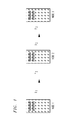
- FIGS. 6A , 6 B and 6 C illustrate embodiments of transmission protocols employing PDF strategies constructed in accordance with the principles of the present invention
- FIG. 10 illustrates a flow diagram of an embodiment of a method of transmitting a message carried out in accordance with the principles of the present invention.
- the memoryless relay channel defined by (3) models a variety of communication problems.
- a wireline network with three terminals depicted in FIG. 1 .
- the idea is that the transmitter (node 1) is wired to the relay (node 2), which is wired to the receiver (node 3).
- Y 2 is a noisy function of X 1 only
- Y 3 is a noisy function of X 2 only.
- the channel distribution (3) satisfies P Y 2 Y 3
- a 1 ,a 2 ) P Y 2
- equation (28) might be considered: P Y 2 Y 3
- Some wireline problems have constraints on the network nodes and not only (capacity constraints) on the network channels or edges. For instance, suppose the relay (node 2) has limited processing power and can either transmit or receive, but not both. For noise-free networks, one might model this via the constraint
- Equation (9) may be written P Y 2 Y 3
- a 1 ,a 2 ) P Y 2
- a relay channel is said to be physically degraded if one can write P Y 2 Y 3
- a 1 ,a 2 ) P Y 2
- Y 2 h 12 d 12 ⁇ / 2 ⁇ X 1 + Z 2 ( 11 )
- Y 3 h 13 d 13 ⁇ / 2 ⁇ X 1 + h 23 d 23 ⁇ / 2 ⁇ X 2 + Z 3 ( 12 )
- X 1 , X 2 , Y 2 , Y 3 , Z 2 , Z 3 are complex random variables
- h ij and d ij are the respective (fading) channel gain and distance between nodes i and j
- the average energies (or powers) of the inputs are constrained as
- h ij is a realization of a complex random variable H ij .
- the channel exhibits Rayleigh fading if the H ij are statistically independent, proper, complex, Gaussian, zero-mean, unit variance random variables.
- Z 2 and Z 3 are independent, proper, complex, Gaussian, unit variance random variables that are independent of X 1 , X 2 , and the H ij for all i, j.
- the model defined by (11) and (12) implicitly permits the relay to transmit and receive at the same time in the same frequency band. However, this is often not possible due to the large differences in transmit and receive energies at the antennas of wireless devices. Most practical wireless relays operate under a half-duplex constraint that one can model as
- FIG. 3 illustrated is a system diagram of a distributed transmitter employing a transmitter and a relay constructed in accordance with the principles of the present invention.
- the transmitter and the relay are arranged in a linear transmission geometry with a receiver wherein the relay is employed on a line between the transmitter and the receiver.
- and d 23
- the relay would be to the left of the transmitter in FIG. 3 for negative d.
- the transmitter is configured to transmit a first codeword to the relay and also to the receiver in a first time block.
- the relay is configured to transmit a second codeword that is based on the first codeword to the receiver in a subsequent second time block.
- the transmitter is further configured to transmit a third codeword to the receiver while the relay is transmitting the second codeword.
- an apparatus for cooperative transmission includes a transmitter that is configured to transmit a first codeword to a relay and subsequently transmit a third codeword while the relay is transmitting a second codeword that is based on the first codeword.
- an apparatus for cooperative transmission includes a relay that is configured to transmit a second codeword concurrently with a third codeword transmitted by a transmitter wherein the second codeword is based on a first codeword transmitted by the transmitter. Therefore, either the transmitter or the relay may provide primary control of the distributed transmission.
- FIG. 4 illustrated is diagram of an embodiment of a transmission protocol employing a decode-and-forward (DF) strategy constructed in accordance with the principles of the present invention.
- the DF strategy of FIG. 4 includes a set of time blocks Block 1 , Block 2 , Block 3 wherein each time block contains a transmitter and a relay portion, as shown.
- the embodiment of FIG. 4 represents a DF strategy for a full-duplex relay, which may decode (listen) and transmit (talk) at the same time.
- the relay transmits x 2 (w b ⁇ 1 ). Note that using randomly-generated codebooks with the above transmission protocol will ensure that the power constraints (13) can be satisfied.
- FIG. 5 illustrated is a diagram of an alternative embodiment of a transmission protocol employing a decode-and-forward (DF) strategy constructed in accordance with the principles of the present invention.
- the DF strategy of FIG. 5 includes a set of time blocks Block 1 , Block 2 , Block 3 , Block 4 wherein each time block contains a transmitter and a relay portion, as shown.
- the alternative embodiment of FIG. 5 also represents a DF strategy for a full-duplex relay, which may decode and transmit at the same time.
- relay channels defined by (11) and (12) with Rayleigh fading are considered. That is, the H ij are independent, proper, complex, Gaussian, zero-mean, unit variance random variables. Suppose further that the transmitter node does not know the realizations of these random variables, the relay knows H 12 only, and the receiver knows H 13 and H 23 only. These restrictions on channel knowledge apply to the practical case where node j can accurately estimate its channel gains H ij but it cannot (or wishes not to) synchronize its waveform with the other transmitters.
- MIMO communication There is a direct relation between MIMO communication and relaying.
- a MIMO channel wherein the “first” MIMO channel input acts as the input of a transmitter node, and the remaining MIMO channel inputs act as inputs of relays that happen to be colocated with the transmitter node.
- D-BLAST encoding is precisely a Block-Markov superposition coding scheme for full-duplex relays. This insight is used to adapt coding strategies for MIMO communication to relay channels. For example, coding protocols are suggested for distributed bit-interleaved coded modulation (BICM), distributed Vertical-BLAST (V-BLAST) and distributed D-BLAST.
- BICM distributed bit-interleaved coded modulation
- V-BLAST distributed Vertical-BLAST
- D-BLAST distributed D-BLAST
- a memoryless relay channel may be defined by the conditional probability distribution: P Y 2 Y 3
- the relay decodes the transmitter message, re-encodes it, and transmits the resulting codeword.
- the relay may use a different codebook than the transmitter.
- This method is employed in traditional multihopping, such as multi-hop wireless transmission systems employing the IEEE 802.11 standard, for example.
- PDF partial decode-and-forward
- PDF has the transmitter split the message into two parts, use superposition encoding to transmit these two parts, and has the relay decode only one of the two parts.
- decode-and-forward strategies Only decode-and-forward strategies and their variations are considered here, of which there are several types. For example, a regular encoding/sliding window decoding decode-and-forward strategy achieves the rate:
- AWGN Additive White Gaussian Noise
- Y _ 2 ⁇ H 12 , H 12 d 12 ⁇ / 2 ⁇ X _ 1 + Z _ 2 ⁇ ⁇ ⁇ and ( 26 )
- Y _ 3 ⁇ H 13 , H 23 , H 13 d 13 ⁇ / 2 ⁇ X _ 1 + H 23 d 23 ⁇ / 2 ⁇ X _ 2 + Z _ 3 ⁇ , ( 27 )
- H st is a complex n t ⁇ n s fading matrix
- d st is the distance between nodes s and t
- X ti be the channel input of device (or node) t at time i.
- the transmitting nodes often have per device and block power constraints
- the model defined by (26) and (27) lets the relay transmit and receive at the same time in the same frequency band. This is often not possible due to large differences in transmit and receive powers.
- Wireless devices usually operate under a half-duplex constraint that one can model by replacing (26) with
- a mode M 2 may be introduced that takes on the values L and T for decode (listen) and transmit (talk), respectively. The transmitter is assumed to always talk and the receiver to always listen. This mode can be considered to be part of the relay's channel input so that (24) becomes
- R max P U _ ⁇ X _ 1 ⁇ X _ 2 ⁇ M 2 ⁇ ⁇ min ⁇ ⁇ I ⁇ ( U _ ; Y _ 2
- V be a column vector of length n 1 and let I be an appropriately sized identity matrix.
- the resulting expressions in (32) with the model defined by (27) and (31) are
- A Direct (1) Use one code.
- Custom code designs Mapping (2) Achieve ergodic and required. quasistatic information (2) Many APP detector rates. updates (steep EXIT).
- B BICM (1) Use one code designed (1) Lose information for AWGN channels. rates. (2) Many APP detector updates (steep EXIT).
- C BICM with (1) Use one code designed (1) Lose information rates Inner Space- for AWGN channels. (unless orthogonal). Time Codes (2) Few detector updates (2) Complex APP detection (flat EXIT). (unless orthogonal).
- D V-BLAST (1) Use codes designed for (1) Lose quasistatic AWGN channels.
- one code with rate R c and length n c is used and the coded bits are mapped directly onto the modulation signal set.
- the coded bits are parsed into blocks of length 2M and these blocks are mapped onto an M-antenna QPSK symbol using Gray mappings.
- BICM For BICM, one code with rate R c and length n c is used and the coded bits are interleaved and then mapped onto the modulation signal set as above.
- BICM with Inner Space-Time Codes one code with rate R c and length n c is used and the coded bits are interleaved and then mapped onto a space-time code.
- V-BLAST encoding is basically the same as multi-level coding or generalized concatenated coding.
- n c /M of the coded bits are mapped onto the first antenna symbol in a first block, another n c /M of these bits are mapped onto a second antenna symbol in a second block, and so forth until the Mth block.
- the symbols corresponding to the entire codeword of length n c are called a layer. Similar steps with other codewords are performed, but the mappings are successively shifted by one block for every codeword.
- FIGS. 6A , 6 B and 6 C illustrated are embodiments of transmission protocols employing PDF strategies constructed in accordance with the principles of the present invention.
- Each of the PDF strategies includes a set of time blocks Block 1 , Block 2 , Block 3 and Block 4 wherein each time block contains a transmitter segment and a relay segment, as shown.
- the embodiments of FIGS. 6A , 6 B and 6 C represent PDF strategies for a half-duplex relay, which may only either decode (listen) or transmit (talk) during each time block.
- FIG. 6A shows an embodiment of a transmission protocol that may be employed with Direct Mapping or BICM.
- the coded bits are mapped onto the modulation signal sets at the transmitter and relay, either with or without bit interleaving. The relay decodes the message bits after having received the first block (
- the first codeword may have a first length and the second and third codewords may have a same second length since they are transmitted concurrently from the relay and transmitter, respectively.
- the first codeword x 1 (w i ) will be transmitted only by the transmitter.
- the second codeword x 2 (w i ) will be transmitted only by the relay, and the third codeword x 3 (w i ) only by the transmitter.
- the relay decodes the first codeword x 1 (w i ) once it is complete.
- the relay is able to decode the entire message corresponding to this codeword even though it has received only the first codeword x 1 (w i ) of the three-part codebook.
- the first codeword length could be half since Block 1 and Block 2 may have different lengths.
- FIG. 6B shows an embodiment of a transmission protocol that may be employed with V-Blast wherein an adaptation of V-BLAST encoding to half-duplex relaying is employed using three different codebooks.
- Each of the three codebooks is used corresponding to each of the three segments in Block 1 and Block 2 of FIG. 6B , as shown.
- the three separate codebooks can have different rates.
- the third codebook can have any rate and will transmit new information.
- n 1 ⁇ n 2 ⁇ n 3 of 1 ⁇ 1 ⁇ 1 rate point (d,R) (0.25,1.5).
- This point may be achieved by using the PDF strategy in FIG. 6B with three rate 1 ⁇ 2 codes.
- the message w b , b odd has to be decoded at the receiver by using the combined decoding graph of both codes that carry this message.
- an encoding/sliding window decoding strategy is being employed.
- FIG. 6C shows an embodiment of a transmission protocol that may be employed with D-Blast wherein a D-BLAST encoding to half-duplex relaying employs two different codebooks.
- a separate codebook is used for each of the two messages in the time blocks Block 1 , Block 2 as shown in FIG. 6C .
- This transmission protocol depicts an intermediate approach where the transmitter segment of Block 1 and the relay segment of Block 2 come from one codebook that is longer than one transmission block, e.g., it may be twice as long.
- the transmitter segment of Block 2 comes from another codebook.
- the relay has to decode w 1 after having received only the transmitter segment of Block 1 from the transmitter.
- a PDF rate curve 705 is shown in FIG. 7 as a function of d.
- a no-relay rate boundary 710 R ⁇ 1.13 bits per use
- a traditional multihopping rate curve 715 with optimized listen and transmit times.
- PDF achieves substantial rate gains over both no-relay transmission and traditional multihopping.
- a PDF rate curve 805 is shown in FIG. 8 as a function of d.
- FIG. 8 also shows a no-relay rate boundary 810 (R ⁇ 0.54 bits per use) and a traditional multihopping rate curve 815 with optimized listen and transmit times.
- Code design is usually done by using density evolution or EXIT charts. The latter approach may be employed to design irregular low-density parity-check (LDPC) codes using a curve-fitting procedure.
- LDPC low-density parity-check
- the coded bits are mapped to QPSK symbols via the Gray mapping.
- a decoder uses the standard graph representation of an LDPC code with variable nodes on the left and check nodes on the right. The left and right nodes are connected by edges whose nodes are chosen with a random permutation that avoids 2-cycles.
- the decoder iterates 60 times between the left and right nodes by using an a posteriori probability (APP) decoder.
- APP a posteriori probability
- R 1 ⁇ 2 without a relay.
- the resulting frame error rates are shown by a FER curve 905 in FIG. 9 .
- the extra loss (as compared to 0.3 dB for the single-antenna case) can be attributed to the short code length and the fading.
- the receiver performs only one detector activation per codeword (multiple detector activations may improve the performance marginally).
- the FER of the relay decoding step is not shown in FIG. 9 because it lies far to the left of the other two curves.
- FIG. 10 illustrated is a flow diagram of an embodiment of a method of transmitting a message carried out in accordance with the principles of the present invention.
- the method of FIG. 10 is for use with a distributed transmission of codewords as depicted by the embodiments of the transmission protocols shown in FIGS. 4 , 5 and 6 , for example, and starts in a step 1005 . Then, in a step 1010 , a first codeword is transmitted from a transmitter to a relay.
- a second codeword which is based on the first codeword, is transmitted from the relay in a step 1015 .
- the transmitter transmits a third codeword concurrently with the second codeword from the relay, in a step 1020 .
- the codewords may be derived from a single codebook, come from separate codebooks or share a portion of one of several codebooks that are employed.
- the first, second and third codewords correspond to a single message and are derived from a single codebook.
- the first and second codewords correspond to a first portion of a message and the third codeword corresponds to a second portion of the message.
- the first codeword is derived from a first codebook
- the second codeword is derived from a second codebook
- the third codeword is derived from a third codebook.
- the method further includes generating first and second data based on a portion of a message, the first codeword corresponds to both first and second data and the second codeword corresponds to only one of the first and second data.
- the first codeword and the second codeword are derived from a first codebook and the third codeword is derived from a second codebook.
- the first codeword and the second codeword may correspond to a first portion of a message and the third codeword may correspond to a second portion of the message. The method ends in a step 1025 .
- the systems include a distributed transmitter that includes a transmitter and a relay.
- the transmitter transmits a codeword for a data block to the relay and to a receiver in a first time block.
- the relay receives and decodes this transmitted codeword.
- the relay transmits a second codeword and the transmitter transmits a third codeword concurrently with the second codeword for the data block.
- the receiver receives first and third codewords from the transmitter and the second codeword from the relay.
- the receiver receives a portion of the codewords in different time blocks, that is, in a time diverse manner.
- the transmitter and relay are not co-located.
Abstract
Description
P Y|X(b|a), aεX,bεY, (1)
where X and Y are random variables taking on values in the discrete and finite alphabets X and Y, respectively. The aim of communication is to transmit reliably a message index W taking on one of M values from a transmitter to a receiver. Suppose that to accomplish this task one transmits a string of n symbols Xn=X1, X2, . . . , Xn over the channel. The rate of communication is then
R=log2(M)/n (2)
Bits per channel use. The maximum rate C at which one can transmit reliably is called the capacity of the channel.
P Y
where X1 is the transmitter's channel input, Y3 is the receiver's channel output, and X2 and Y2 are the relay's input and output, respectively. The idea is that the transmitter and receiver can only transmit and receive, respectively, but the relay can both transmit and receive. Suppose that the transmitter and relay transmit the strings X1 n=X11, X12, . . . , X1n and X2 n=X21, X22, . . . , X2n, respectively, over the channel. Suppose further that the relay can react quickly so that its input X2i can be any function of its past outputs Y2 i−1. The relay channel is said to be memoryless if one has
P Y
for all a1 i, a2 i, b2 i, b3 i, and i=1, 2, . . . , n. Only memoryless channels will be considered. Again, the maximum rate C at which one can transmit reliably is called the capacity of the channel.
P Y
The relay network is memoryless if the natural extension of the condition (4) is true, that is, if the ith channel outputs Yti, t=2,3, . . . , T, depend only on the ith channel inputs Xti, t=1, 2, . . . , T−1, given the message, the present (or ith) and past channels inputs, and the past channel outputs. The capacity C is again the maximum rate at which one can transmit reliably.
P Y
for all a1, a2, b2, b3. If the channels are essentially noise-free, equation (28) might be considered:
P Y
where 1(•) is the indicator function that takes on the value one if its argument is true and is zero otherwise.
Note that (6) is no longer true. However, equation (9) may be written
P Y
for all a1, a2, b2, b3. More generally, a relay channel is said to be physically degraded if one can write
P Y
For all a1, a2, b2, b3. The channels (6), (7), and (9) are therefore physically degraded.
where X1, X2, Y2, Y3, Z2, Z3 are complex random variables, hij and dij are the respective (fading) channel gain and distance between nodes i and j, and α is an attenuation exponent (e.g., α=2 for free space propagation). The average energies (or powers) of the inputs are constrained as
The idea of the above model is that the wireless channel permits broadcasting (X1 affects both Y2 and Y3) but that this causes interference (X1 and X2 interfere at node 3).
Note the similarity between (8) and (14). Either with or with out the half-duplex constraint, the wireless models considered do not satisfy (10) and are hence not physically degraded.
where I(X;Y) is the mutual information between random variables X and Y. For the complex-alphabet AWGN model:
Y=X+Z, (16)
where
and Z is proper, Gaussian, unit-variance, and independent of X. The maximization in (15) is now performed over all probability density functions pX(•) and the result is
C=log2(1+P) bits per channel use, (17)
where it may be recalled that the channel has complex alphabets.
Next, a consideration of random coding strategies that achieve good rates for the relay channels of interest is presented.
x 1(w b ,w b1)= x 1′(w b)+β x 2(w b1), (19)
where β=√{square root over ((P1−P1)/P2)}. In block b the relay transmits x 2(wb−1). Note that using randomly-generated codebooks with the above transmission protocol will ensure that the power constraints (13) can be satisfied.
R<log(1+P 1) and (20)
R<log(1+P 1+(1+β)2 P 2), (21)
where the first and second bounds arise due to the respective relay and receiver decoding steps.
P Y
where aεγ2, bεγ3, cεχ1, dεχ2, Y2 and Y3 are the relay and receiver channel outputs, respectively, and X1 and X2 are the transmitter and relay channel inputs, respectively.
The block Markov superposition encoding scheme used to achieve (23) has a diagonally layered structure that is basically the same as D-BLAST encoding. However, for half-duplex devices an improved transmission rate employing the PDF strategy may be represented by
where U-[X1,X2]-[Y2,Y3] forms a Markov chain. Observe that in (24)
I(X 1 X 2 ;Y 3)=I(UX 2 ;Y 2)+I(X 1 ;Y 3 |UX 2). (25)
The PDF rate (24) is thus the sum of a DF rate (23) with U replacing X1 and a single-hop rate I(X1;Y3|UX2).
where X t, t=1, 2, and Y t and Z t, t=2, 3, are complex column vectors of length nt, Hst is a complex nt×ns fading matrix, dst is the distance between nodes s and t, and α is an attenuation exponent (e.g., α=2 for free space propagation). The Z t have statistically independent, proper, complex, Gaussian, zero-mean, unit variance entries and are statistically independent of each other and all the X t and Hst. Further suppose that Hst is statistically independent of X t, t=1, 2,Z t, T=2, 3, and all other fading matrices. Rayleigh fading has Hst that have statistically independent, proper, complex, Gaussian, zero-mean, unit variance entries. Now, consider the linear geometry depicted in
where ∥X∥2=X † X and X † is the complex-conjugate transpose of X. Alternatively, one might use the network constraint
or, perhaps, the symbol constraints
E[∥X ti∥2 ]≦P t , t=1,2, i=1,2, . . . n. (30)
Only (30) is considered below.
Alternatively, a mode M2 may be introduced that takes on the values L and T for decode (listen) and transmit (talk), respectively. The transmitter is assumed to always talk and the receiver to always listen. This mode can be considered to be part of the relay's channel input so that (24) becomes
where U is a column vector of length n1. Note that if M2 is known ahead of time by the receiver, then one loses the gain I(M2;Y 3) above. On the other hand, this gain might be difficult to realize because the relay must switch rapidly between M2=L and M2=T. For simplicity, this gain will be ignored here.
where the p(h) and p({tilde over (h)}) are Gaussian fading distributions (h and {tilde over (h)} are matrices in general). Note that for d12≦d13 it is best to choose β(L)=1 and β(T)=0. Moreover, this distribution is basically the same as using a strategy depicted in
| TABLE 1 |
| Comparison of MIMO Coded Modulation Methods |
| Strategy | Advantages | Disadvantages |
| (A) Direct | (1) Use one code. | (1) Custom code designs |
| Mapping | (2) Achieve ergodic and | required. |
| quasistatic information | (2) Many APP detector | |
| rates. | updates (steep EXIT). | |
| (B) BICM | (1) Use one code designed | (1) Lose information |
| for AWGN channels. | rates. | |
| (2) Many APP detector | ||
| updates (steep EXIT). | ||
| (C) BICM with | (1) Use one code designed | (1) Lose information rates |
| Inner Space- | for AWGN channels. | (unless orthogonal). |
| Time Codes | (2) Few detector updates | (2) Complex APP detection |
| (flat EXIT). | (unless orthogonal). | |
| (D) V-BLAST | (1) Use codes designed for | (1) Lose quasistatic |
| AWGN channels. | information rates (many | |
| (2) Achieve ergodic | codes). | |
| information rates. | (2) Interference | |
| (3) Few soft detector | cancellation. | |
| updates (flat EXIT). | (3) Increased delay | |
| (reduced reliability). | ||
| (E) D-BLAST | (1) Use one code designed | (1) Interference |
| for AWGN channels. | cancellation. | |
| (2) Achieve ergodic and | (2) Increased delay | |
| quasistatic information | (reduced reliability). | |
| rates | (3) Error propagation. | |
| (3) Few soft detector | ||
| updates (flat EXIT). | ||
x (w i)=[ x 1(w i), x 2(w i), x 3(w i)] (37)
Therefore, one codebook is generated and each of its codewords {x}(wi) of length n is split into three codewords {x}1(wi), {x}2(wi) and {x}3(wi) with respective lengths m1, m2 and m3 where m1+m2+m3=n. The coded bits are mapped onto the modulation signal sets at the transmitter and relay, either with or without bit interleaving. The relay decodes the message bits after having received the first block (Block 1) of outputs from the transmitter.
x (w 1)= x 1(w 1 ′, w 1″) and x 2(w 1′) and x 3(w 2), (38)
where wi=[wi′, wi″].
x (w i)=[ x 1(w i), x 2(w i)] and x 3(w i). (39)
This transmission protocol depicts an intermediate approach where the transmitter segment of
Claims (18)
Priority Applications (1)
| Application Number | Priority Date | Filing Date | Title |
|---|---|---|---|
| US11/425,608 US9025641B2 (en) | 2006-06-21 | 2006-06-21 | Distributed transmission involving cooperation between a transmitter and a relay |
Applications Claiming Priority (1)
| Application Number | Priority Date | Filing Date | Title |
|---|---|---|---|
| US11/425,608 US9025641B2 (en) | 2006-06-21 | 2006-06-21 | Distributed transmission involving cooperation between a transmitter and a relay |
Publications (2)
| Publication Number | Publication Date |
|---|---|
| US20070297498A1 US20070297498A1 (en) | 2007-12-27 |
| US9025641B2 true US9025641B2 (en) | 2015-05-05 |
Family
ID=38873543
Family Applications (1)
| Application Number | Title | Priority Date | Filing Date |
|---|---|---|---|
| US11/425,608 Active 2029-06-15 US9025641B2 (en) | 2006-06-21 | 2006-06-21 | Distributed transmission involving cooperation between a transmitter and a relay |
Country Status (1)
| Country | Link |
|---|---|
| US (1) | US9025641B2 (en) |
Cited By (2)
| Publication number | Priority date | Publication date | Assignee | Title |
|---|---|---|---|---|
| CN107210783A (en) * | 2014-09-29 | 2017-09-26 | 华为技术有限公司 | The system and method for carrying out joint MIMO transmission and compression using cooperating relay to reduce interference |
| TWI706636B (en) * | 2017-06-01 | 2020-10-01 | 聯發科技股份有限公司 | Wireless communication methods using codebooks from a qc-ldpc code |
Families Citing this family (16)
| Publication number | Priority date | Publication date | Assignee | Title |
|---|---|---|---|---|
| US7821980B2 (en) * | 2006-08-03 | 2010-10-26 | Nokia Corporation | Variable rate soft information forwarding |
| US8942306B2 (en) * | 2007-03-07 | 2015-01-27 | Marvell World Trade Ltd. | Codebook selection for transmit beamforming |
| TWI442737B (en) * | 2007-03-07 | 2014-06-21 | Marvell World Trade Ltd | Codebook selection for transmit beamforming |
| WO2008146261A2 (en) * | 2007-05-31 | 2008-12-04 | Nokia Corporation | Distributed iterative decoding for co-operative diversity |
| US9300371B1 (en) | 2008-03-07 | 2016-03-29 | Marvell International Ltd. | Beamforming systems and methods |
| US8638875B1 (en) | 2008-04-15 | 2014-01-28 | Marvell International Ltd. | Transmit beamforming systems and methods |
| US20090252146A1 (en) * | 2008-04-03 | 2009-10-08 | Microsoft Corporation | Continuous network coding in wireless relay networks |
| WO2010050785A2 (en) * | 2008-10-30 | 2010-05-06 | 한국전자통신연구원 | Data transmission and reception method in cooperative communication system |
| KR101466754B1 (en) * | 2008-11-04 | 2014-11-27 | 삼성전자주식회사 | Wireless network using superposition coding scheme |
| KR102051527B1 (en) * | 2013-02-12 | 2019-12-03 | 삼성전자주식회사 | Cooperative communication system,transmitter,relay and receiver based on network compressandforward |
| WO2015079386A1 (en) * | 2013-11-26 | 2015-06-04 | Telefonaktiebolaget L M Ericsson (Publ) | Improving data rates of short message noisy network coding and decode-and forward relaying |
| CN104079380B (en) * | 2014-07-07 | 2017-04-19 | 西安电子科技大学 | Distributed type combined information source-channel superposition coding and combined decoding method |
| US11018795B2 (en) | 2014-09-29 | 2021-05-25 | The Regents Of The University Of California | Methods and apparatus for coding for interference network |
| CN105703877B (en) * | 2014-11-26 | 2019-12-17 | 中兴通讯股份有限公司 | superposition coding and decoding method and device, transmitter and receiver |
| WO2017075489A1 (en) * | 2015-10-30 | 2017-05-04 | Kyocera Corporation | Selection of decoding level at signal forwarding devices |
| US10715278B2 (en) * | 2017-09-26 | 2020-07-14 | Purdue Research Foundation | Transcoding wireless communication system |
Citations (12)
| Publication number | Priority date | Publication date | Assignee | Title |
|---|---|---|---|---|
| US5136663A (en) * | 1988-12-23 | 1992-08-04 | Matsushita Electric Industrial Co., Ltd. | Vector quantization image processing apparatus |
| US5339164A (en) * | 1991-12-24 | 1994-08-16 | Massachusetts Institute Of Technology | Method and apparatus for encoding of data using both vector quantization and runlength encoding and using adaptive runlength encoding |
| US20040095920A1 (en) * | 2002-11-19 | 2004-05-20 | Lippman Andrew Benjamin | Method for automatic signal routing in ad hoc networks |
| US20050265387A1 (en) * | 2004-06-01 | 2005-12-01 | Khojastepour Mohammad A | General code design for the relay channel and factor graph decoding |
| US20060022847A1 (en) * | 2004-07-30 | 2006-02-02 | Yuan Xing Lee | Method and apparatus for data coding for high density recording channels exhibiting low frequency contents |
| US20060165189A1 (en) * | 2005-01-21 | 2006-07-27 | Satoshi Tamaki | Adaptive modulation scheme and coding rate control method |
| US7123875B1 (en) * | 1999-11-04 | 2006-10-17 | Xm Satellite Radio, Inc. | System and method for multipoint distribution of satellite digital audio radio service |
| US20060291440A1 (en) * | 2005-06-01 | 2006-12-28 | Ntt Docomo. Inc. | Communication relay apparatus and communication receiver |
| US20070010196A1 (en) * | 2005-07-06 | 2007-01-11 | Nortel Networks Limited | Coverage improvement in wireless systems with fixed infrastructure based relays |
| US20070217432A1 (en) * | 2006-03-16 | 2007-09-20 | Molisch Andreas F | Cooperative relay networks using rateless codes |
| US7301983B1 (en) * | 1998-01-05 | 2007-11-27 | Intel Corporation | Method for using codebook indexing to achieve high bit densities in a direct-sequence CDMA spread spectrum communication system |
| US7920501B2 (en) * | 2004-12-30 | 2011-04-05 | Telefonaktiebolaget Lm Ericsson (Publ) | Method and arrangement for bi-directional relaying in wireless communication systems |
-
2006
- 2006-06-21 US US11/425,608 patent/US9025641B2/en active Active
Patent Citations (12)
| Publication number | Priority date | Publication date | Assignee | Title |
|---|---|---|---|---|
| US5136663A (en) * | 1988-12-23 | 1992-08-04 | Matsushita Electric Industrial Co., Ltd. | Vector quantization image processing apparatus |
| US5339164A (en) * | 1991-12-24 | 1994-08-16 | Massachusetts Institute Of Technology | Method and apparatus for encoding of data using both vector quantization and runlength encoding and using adaptive runlength encoding |
| US7301983B1 (en) * | 1998-01-05 | 2007-11-27 | Intel Corporation | Method for using codebook indexing to achieve high bit densities in a direct-sequence CDMA spread spectrum communication system |
| US7123875B1 (en) * | 1999-11-04 | 2006-10-17 | Xm Satellite Radio, Inc. | System and method for multipoint distribution of satellite digital audio radio service |
| US20040095920A1 (en) * | 2002-11-19 | 2004-05-20 | Lippman Andrew Benjamin | Method for automatic signal routing in ad hoc networks |
| US20050265387A1 (en) * | 2004-06-01 | 2005-12-01 | Khojastepour Mohammad A | General code design for the relay channel and factor graph decoding |
| US20060022847A1 (en) * | 2004-07-30 | 2006-02-02 | Yuan Xing Lee | Method and apparatus for data coding for high density recording channels exhibiting low frequency contents |
| US7920501B2 (en) * | 2004-12-30 | 2011-04-05 | Telefonaktiebolaget Lm Ericsson (Publ) | Method and arrangement for bi-directional relaying in wireless communication systems |
| US20060165189A1 (en) * | 2005-01-21 | 2006-07-27 | Satoshi Tamaki | Adaptive modulation scheme and coding rate control method |
| US20060291440A1 (en) * | 2005-06-01 | 2006-12-28 | Ntt Docomo. Inc. | Communication relay apparatus and communication receiver |
| US20070010196A1 (en) * | 2005-07-06 | 2007-01-11 | Nortel Networks Limited | Coverage improvement in wireless systems with fixed infrastructure based relays |
| US20070217432A1 (en) * | 2006-03-16 | 2007-09-20 | Molisch Andreas F | Cooperative relay networks using rateless codes |
Non-Patent Citations (2)
| Title |
|---|
| Kramer; "Communication Strategies and Coding for Relaying;" Institute for Mathematics and its Applications (IMA); 2005 Summer Program on Wireless Communications, University of Minnesota, Minneapolis, MN; Jun. 22-Jul. 1, 2005; pp. 1-13. |
| Kramer; "Distributed and Layered Codes for Relaying;" Proc. Asilomar Conf. on Signals, Systems and Computers, Pacific Grove, CA; Oct. 30-Nov. 2, 2005; pp. 1752-1756. |
Cited By (3)
| Publication number | Priority date | Publication date | Assignee | Title |
|---|---|---|---|---|
| CN107210783A (en) * | 2014-09-29 | 2017-09-26 | 华为技术有限公司 | The system and method for carrying out joint MIMO transmission and compression using cooperating relay to reduce interference |
| CN107210783B (en) * | 2014-09-29 | 2020-06-02 | 华为技术有限公司 | System and method for reducing interference using cooperative relaying for joint MIMO transmission and compression |
| TWI706636B (en) * | 2017-06-01 | 2020-10-01 | 聯發科技股份有限公司 | Wireless communication methods using codebooks from a qc-ldpc code |
Also Published As
| Publication number | Publication date |
|---|---|
| US20070297498A1 (en) | 2007-12-27 |
Similar Documents
| Publication | Publication Date | Title |
|---|---|---|
| US9025641B2 (en) | Distributed transmission involving cooperation between a transmitter and a relay | |
| Hunter et al. | Outage analysis of coded cooperation | |
| US8416730B2 (en) | Distributed turbo coding and relaying protocols | |
| Zimmermann et al. | On the performance of cooperative relaying protocols in wireless networks | |
| Peng et al. | On the performance analysis of network-coded cooperation in wireless networks | |
| EP2202894B1 (en) | Relay station for a mobile communication system | |
| US20050265387A1 (en) | General code design for the relay channel and factor graph decoding | |
| EP2202904B1 (en) | A relay station and a decoder | |
| Ejaz et al. | Jointly optimized multiple Reed-Muller codes for wireless half-duplex coded-cooperative network with joint decoding | |
| Li et al. | Outage probability analysis of coded cooperation with multiple relays | |
| Kramer | Distributed and layered codes for relaying | |
| Zhou et al. | Outage probability of correlated binary source transmission over fading multiple access channels | |
| Bui et al. | A decode and forward cooperation scheme with soft relaying in wireless communication | |
| US7865800B2 (en) | System and method for cooperation diversity through coding | |
| Kramer | Communication strategies and coding for relaying | |
| Cao et al. | Cooperative coding using serial concatenated convolutional codes | |
| Hairej et al. | Cooperative diversity using soft decision and distributed decoding | |
| Makki et al. | On the performance of HARQ-based RF-FSO links | |
| Madhusudhanan et al. | Outage analysis of opportunistic‐based hybrid decode‐amplify‐forward relaying in polar code environment | |
| Holliday et al. | Cross-layer design for MIMO systems | |
| Rodor et al. | Optimized Distributed Linear Block Codes For Single Relay Cooperative Wireless Communications | |
| Altın | Distributed space‐time block coding based cooperative generalized spatial modulation | |
| Guo et al. | An outage-optimal distributed coded cooperation scheme based on opportunistic relaying | |
| Elia et al. | Asymptotically optimal cooperative wireless networks without constellation expansion | |
| Diallo et al. | Optimization of Polar Codes in Virtual MIMO Systems |
Legal Events
| Date | Code | Title | Description |
|---|---|---|---|
| AS | Assignment |
Owner name: LUCENT TECHNOLOGIES INC., NEW JERSEY Free format text: ASSIGNMENT OF ASSIGNORS INTEREST;ASSIGNOR:KRAMER, GERHARD G.;REEL/FRAME:017831/0746 Effective date: 20060620 |
|
| AS | Assignment |
Owner name: CREDIT SUISSE AG, NEW YORK Free format text: SECURITY INTEREST;ASSIGNOR:ALCATEL-LUCENT USA INC.;REEL/FRAME:030510/0627 Effective date: 20130130 |
|
| AS | Assignment |
Owner name: ALCATEL-LUCENT USA INC., NEW JERSEY Free format text: RELEASE BY SECURED PARTY;ASSIGNOR:CREDIT SUISSE AG;REEL/FRAME:033949/0016 Effective date: 20140819 |
|
| FEPP | Fee payment procedure |
Free format text: PAYOR NUMBER ASSIGNED (ORIGINAL EVENT CODE: ASPN); ENTITY STATUS OF PATENT OWNER: LARGE ENTITY |
|
| AS | Assignment |
Owner name: ALCATEL-LUCENT USA INC., NEW JERSEY Free format text: MERGER AND CHANGE OF NAME;ASSIGNORS:LUCENT TECHNOLOGIES INC.;ALCATEL USA MARKETING, INC.;ALCATEL USA SOURCING, INC.;AND OTHERS;REEL/FRAME:035410/0065 Effective date: 20081101 |
|
| STCF | Information on status: patent grant |
Free format text: PATENTED CASE |
|
| AS | Assignment |
Owner name: ALCATEL LUCENT, FRANCE Free format text: ASSIGNMENT OF ASSIGNORS INTEREST;ASSIGNOR:ALCATEL-LUCENT USA INC.;REEL/FRAME:035426/0170 Effective date: 20150415 |
|
| MAFP | Maintenance fee payment |
Free format text: PAYMENT OF MAINTENANCE FEE, 4TH YEAR, LARGE ENTITY (ORIGINAL EVENT CODE: M1551); ENTITY STATUS OF PATENT OWNER: LARGE ENTITY Year of fee payment: 4 |
|
| MAFP | Maintenance fee payment |
Free format text: PAYMENT OF MAINTENANCE FEE, 8TH YEAR, LARGE ENTITY (ORIGINAL EVENT CODE: M1552); ENTITY STATUS OF PATENT OWNER: LARGE ENTITY Year of fee payment: 8 |