US9022743B2 - Segmented thermally insulating coating - Google Patents
Segmented thermally insulating coating Download PDFInfo
- Publication number
- US9022743B2 US9022743B2 US13/307,295 US201113307295A US9022743B2 US 9022743 B2 US9022743 B2 US 9022743B2 US 201113307295 A US201113307295 A US 201113307295A US 9022743 B2 US9022743 B2 US 9022743B2
- Authority
- US
- United States
- Prior art keywords
- thermally insulating
- surface regions
- insulating topcoat
- regions
- topcoat
- Prior art date
- Legal status (The legal status is an assumption and is not a legal conclusion. Google has not performed a legal analysis and makes no representation as to the accuracy of the status listed.)
- Active, expires
Links
Images


Classifications
-
- F—MECHANICAL ENGINEERING; LIGHTING; HEATING; WEAPONS; BLASTING
- F01—MACHINES OR ENGINES IN GENERAL; ENGINE PLANTS IN GENERAL; STEAM ENGINES
- F01D—NON-POSITIVE DISPLACEMENT MACHINES OR ENGINES, e.g. STEAM TURBINES
- F01D5/00—Blades; Blade-carrying members; Heating, heat-insulating, cooling or antivibration means on the blades or the members
- F01D5/12—Blades
- F01D5/28—Selecting particular materials; Particular measures relating thereto; Measures against erosion or corrosion
- F01D5/288—Protective coatings for blades
-
- F—MECHANICAL ENGINEERING; LIGHTING; HEATING; WEAPONS; BLASTING
- F01—MACHINES OR ENGINES IN GENERAL; ENGINE PLANTS IN GENERAL; STEAM ENGINES
- F01D—NON-POSITIVE DISPLACEMENT MACHINES OR ENGINES, e.g. STEAM TURBINES
- F01D25/00—Component parts, details, or accessories, not provided for in, or of interest apart from, other groups
- F01D25/08—Cooling; Heating; Heat-insulation
- F01D25/14—Casings modified therefor
- F01D25/145—Thermally insulated casings
-
- C—CHEMISTRY; METALLURGY
- C23—COATING METALLIC MATERIAL; COATING MATERIAL WITH METALLIC MATERIAL; CHEMICAL SURFACE TREATMENT; DIFFUSION TREATMENT OF METALLIC MATERIAL; COATING BY VACUUM EVAPORATION, BY SPUTTERING, BY ION IMPLANTATION OR BY CHEMICAL VAPOUR DEPOSITION, IN GENERAL; INHIBITING CORROSION OF METALLIC MATERIAL OR INCRUSTATION IN GENERAL
- C23C—COATING METALLIC MATERIAL; COATING MATERIAL WITH METALLIC MATERIAL; SURFACE TREATMENT OF METALLIC MATERIAL BY DIFFUSION INTO THE SURFACE, BY CHEMICAL CONVERSION OR SUBSTITUTION; COATING BY VACUUM EVAPORATION, BY SPUTTERING, BY ION IMPLANTATION OR BY CHEMICAL VAPOUR DEPOSITION, IN GENERAL
- C23C4/00—Coating by spraying the coating material in the molten state, e.g. by flame, plasma or electric discharge
-
- Y—GENERAL TAGGING OF NEW TECHNOLOGICAL DEVELOPMENTS; GENERAL TAGGING OF CROSS-SECTIONAL TECHNOLOGIES SPANNING OVER SEVERAL SECTIONS OF THE IPC; TECHNICAL SUBJECTS COVERED BY FORMER USPC CROSS-REFERENCE ART COLLECTIONS [XRACs] AND DIGESTS
- Y10—TECHNICAL SUBJECTS COVERED BY FORMER USPC
- Y10T—TECHNICAL SUBJECTS COVERED BY FORMER US CLASSIFICATION
- Y10T29/00—Metal working
- Y10T29/49—Method of mechanical manufacture
- Y10T29/49229—Prime mover or fluid pump making
Definitions
- components that are exposed to high temperatures typically include protective coatings.
- components such as turbine blades, turbine vanes, blade outer air seals, combustor liners and compressor components typically include one or more coating layers that serve to protect the component from erosion, oxidation, corrosion or the like and thereby enhance component durability and maintain efficient engine operation.
- a turbine engine article that includes a substrate and a thermally insulating topcoat on a surface of the substrate.
- the surface of the substrate includes a surface pattern that defines first surface regions and second surface regions.
- the first surface regions include incubation sites that are favorable for deposition of the thermally insulating topcoat and the second surface regions are less favorable for deposition of the thermally insulating topcoat.
- the thermally insulating topcoat includes segmented portions that are separated by faults extending through the thermally insulating topcoat from the second regions.
- the method includes providing a substrate that has a surface pattern defining first surface regions and second surface regions.
- the first surface regions include incubation sites that are favorable for deposition of a thermally insulating topcoat and the second surface regions are less favorable for deposition of the thermally insulating topcoat.
- the thermally insulating topcoat is deposited onto the surface pattern such that the thermally insulating topcoat forms with faults that extend through the topcoat from the second regions to separate segmented portions of the topcoat.
- FIG. 1 illustrates an example turbine engine.
- FIG. 2 illustrates a portion of an example turbine engine component.
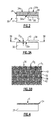
- FIG. 3A illustrates an isolated view of an example substrate of a turbine engine component.
- FIG. 3B illustrates another isolated view of the substrate of FIG. 3A .
- FIG. 4 illustrates an example turbine engine component at an intermediate stage of depositing a topcoat.
- FIG. 1 illustrates a schematic view of selected portions of an example turbine engine 10 , which serves as an exemplary operating environment for a turbine engine component 30 ( FIG. 2 ).
- the turbine engine component 30 includes a thermally insulating topcoat 34 that has pre-existing locations for releasing energy associated with internal stresses that are caused by exposure to elevated temperatures.
- the turbine engine 10 is suspended from an engine pylon 12 of an aircraft, as is typical of an aircraft designed for subsonic operation.
- the turbine engine 10 is circumferentially disposed about an engine centerline, or axial centerline axis A.
- the turbine engine 10 includes a fan 14 , a compressor 16 having a low pressure compressor section 16 a and a high pressure compressor section 16 b , a combustion section 18 , and a turbine 20 having a high pressure turbine section 20 b and a low pressure turbine section 20 a.
- air compressed in the compressors 16 a , 16 b is mixed with fuel that is burned in the combustion section 18 and expanded in the turbines 20 a and 20 b .
- the turbines 20 a and 20 b are coupled to drive, respectively, rotors 22 a and 22 b (e.g., spools) to rotationally drive the compressors 16 a , 16 b and the fan 14 in response to the expansion.
- the rotor 22 a drives the fan 14 through a gear train 24 .
- the turbine engine 10 is a high bypass, geared turbofan arrangement, although the examples herein can also be applied in other engine configurations.
- the bypass ratio of bypass airflow (D) to core airflow (C) is greater than 10:1
- the fan 14 diameter is substantially larger than the diameter of the low pressure compressor 16 a and the low pressure turbine 20 a has a pressure ratio that is greater than 5:1.
- the gear train 24 can be any known suitable gear system, such as a planetary gear system with orbiting planet gears, planetary system with non-orbiting planet gears, or other type of gear system.
- the gear train 24 has a constant gear ratio. It is to be appreciated that the illustrated engine configuration and parameters are only exemplary and that the examples disclosed herein are applicable to other turbine engine configurations, including ground-based turbines that do not have fans.
- the low pressure compressor section 16 a , the high pressure compressor section 16 b , the high pressure turbine section 20 b , the low pressure turbine section 20 a and the combustor 18 include turbine engine components, generally designated as components 30 , that are subjected to relatively high temperatures during engine operation.
- the components 30 include one or more of rotatable blades, stationary vanes, outer air seals, combustors and liners, heat shields, exhaust cases and turbine frames, as well as any component that utilizes a thermal barrier coating, for example.
- FIG. 2 shows a portion of one of the components 30 .
- the component 30 includes a substrate 32 and a thermally insulating topcoat 34 disposed on a surface 32 a of the substrate 32 .
- the surface 32 a includes a surface pattern 36 with regard to first surface regions 38 and second surface regions 40 .
- the surface regions 38 and 40 are distinguished by their favorability for deposition of the thermally insulating topcoat 34 .
- the first surface regions 38 include incubation sites 42 that are favorable for deposition of the thermally insulating topcoat 34 .
- the second surface regions 40 do not have incubation sites, have fewer incubation sites per unit of area than the first surface regions 38 or have incubation sites that are less favorable for deposition than the incubation sites 42 of the first surface regions 38 .
- the second surface regions 40 are thus less favorable for deposition of the thermally insulating topcoat 34 relative to the first surface regions 38 .
- the first surface regions 38 have a first surface roughness and the second surface regions 40 have a second surface roughness that is less than the first surface roughness.
- the first surface roughness and the second surface roughness are defined by the parameter R a , for example.
- the surface roughness is provided by masking off the areas of the second surface regions 40 and peening the remaining areas of the first surface regions 38 to a predetermined roughness.
- the surface roughness is provided by grit blasting the entire surface of the substrate 32 , masking off the areas of the first surface regions 38 and chemically milling the remaining areas to form the second surface regions 40 to smooth the roughness created by the milling.
- the roughness is provided during formation of the substrate 32 , in a casting process, for example.
- the roughness is provided by laser or chemical etching, or selectively depositing fine grit particles on the areas of the first surface regions 38 .
- the fine grit particles are of the same or similar composition as the substrate 32 and/or thermally insulating topcoat 34 .
- the relative roughness of the first surface regions 38 versus the roughness of the second surface regions 40 serves as the incubation sites 42 that are favorable for deposition of the thermally insulating topcoat 34 .
- the roughness defines random peaks and valleys in the first surface regions 38 .
- the peaks and valleys provide surface discontinuities that are favorable for the deposition of the thermally insulating topcoat 34 .
- the surface discontinuities have a maximum dimension of 5 to 10 micrometers with regard to an average distance between the peaks and valleys. If fine grit particles are used, the particles are 5 to 10 micrometers in average diameter.
- the maximum dimension (e.g., height) of the surface discontinuities is less than 100 micrometers. In a further alternative, the maximum dimension of the surface discontinuities is less than 25 micrometers.
- the thermally insulating topcoat 34 includes segmented portions 34 a and 34 b that are separated by faults 44 (one shown) that extend through the thermally insulating topcoat 34 from the second region 40 . It is to be understood that the component 30 includes multiple segmented portions separated by multiple faults 44 .
- the faults 44 facilitate reducing internal stresses within the thermally insulating topcoat 34 that may occur from sintering of the topcoat material at relatively high surface temperatures within the turbine engine 10 during operation.
- the thermally insulating topcoat 34 can be exposed to temperatures of 2500° F. (1370° C.) or higher, which may cause sintering of the thermally insulating topcoat 34 .
- the sintering may result in partial melting, densification, and diffusional shrinkage of the thermally insulating topcoat 34 and thereby induce internal stresses.
- the faults 44 provide pre-existing locations for releasing energy associated with the internal stresses (e.g., reducing shear and radial stresses). That is, the energy associated with the internal stresses may be dissipated in the faults 44 such that there is less energy available for causing delamination cracking between the thermally insulating topcoat 34 and the underlying substrate 32 .
- the faults 44 may also serve as expansion gaps for thermal expansion of the topcoat 34 .
- the structure of the faults 44 can vary depending upon the process used to deposit the thermally insulating topcoat 34 and the surface pattern 36 , for instance.
- the faults 44 are gaps between neighboring segmented portions 34 a and 34 b .
- the faults 44 are microstructural discontinuities between neighboring segmented portions 34 a and 34 b .
- the segmented portions 34 a and 34 b have a columnar grain microstructure 46 and the faults 44 are microstructural discontinuities between neighboring clusters or “cells” of grains.
- the faults 44 may be considered to be planes of weakness in the thermally insulating topcoat 34 such that the segmented portions 34 a and 34 b can thermally expand and contract without producing a significant amount of stress from restriction of a neighboring segmented portion 34 a or 34 b and/or any cracking that does occur in the thermally insulating topcoat 34 from internal stresses is dissipated through propagation of the crack along the faults 44 .
- the faults 44 facilitate dissipation of internal stress energy within the thermally insulating topcoat 34 .
- the surface pattern 36 in this example is a grid that includes the second surface regions 40 arranged as interconnected borders that circumscribe the first surface regions 38 .
- the grid is thus a cellular pattern.
- the interconnected borders form circular cells that induce approximately circular or approximately hexagonal shapes of the segmented portions 34 a and 34 b of the thermally insulating topcoat 34 .
- interconnected border geometries can be provided to form other geometrically-shaped cells, combinations of different geometrically-shaped cells, non-geometric cells, non-cellular shapes or complex shapes or patterns.
- each of the first surface regions 38 defines a maximum dimension (D 1 ) and the borders define a minimum dimension (D 2 ) of the second surface regions 40 .
- the dimensions D 1 and D 2 are predefined to provide a desired fault density and degree of thermal protection. For example, if dimension D 2 is too large relative to dimension D 1 , the faults 44 form as relatively large gaps in the thermally insulating topcoat 34 and debit thermal protection.
- a predetermined ratio of D 1 /D 2 (D 1 divided by D 2 ) is selected to provide a balance of thermal protection and fault formation.
- the ratio is from 6 to 50. In a further example, the ratio is from 7.5 to 25.
- the geometry of the incubation sites 42 with regard to dimensions is also controlled.
- the incubation sites 42 such as the surface discontinuities, have a maximum dimension of D 3 , and D 2 is greater than D 3 . Controlling D 2 to be greater than D 3 ensures that the second surface regions 40 are discernible from the first surface regions 38 to form the segmented portions 34 a and 34 b.
- the selected maximum dimension (D 1 ) of the first surface regions 38 is smaller than a spacing of cracks that would occur naturally, without the faults 44 , which makes the thermally insulating topcoat 34 more resistant to spalling and delamination.
- the substrate 32 optionally includes a metallic alloy, a metallic bond coat or both.
- the metallic alloy is a superalloy material, such as a nickel-based or cobalt-based alloy.
- the topcoat 34 is deposited directly on to the superalloy substrate.
- the superalloy includes a bond coat thereon to enhance bonding with the topcoat 34 .
- the bond coat includes a nickel alloy, platinum, gold, silver, or MCrAlY where the M includes at least one of nickel, cobalt, iron, or combination thereof, Cr is chromium, Al is aluminum and Y is yttrium.
- the thermally insulating topcoat 34 is a ceramic material that is selected to provide a desired thermal resistance for the given end use application.
- the thermally insulating topcoat 34 is or includes yttria stabilized zirconia, hafnia, gadolinia, gadolinia zirconate, molybdate, alumina or combinations thereof and can be graded or ungraded. Given this description, one of ordinary skill in the art will recognize other types of ceramic materials to meet their particular needs.
- the deposition process includes a thermal spray technique.
- One example thermal spray technique that is capable of producing the desired columnar grain microstructure 46 is a suspension or solution plasma spray process in which particles of the coating material are suspended in a mixture with a liquid or semi-liquid carrier. The mixture is sprayed into a plasma discharge that volatilizes the carrier and melts or partially melts the coating material. The melted or partially melted coating material then kinetically deposits onto the first surface regions 38 of the surface pattern 36 of the substrate 32 .
- the substrate 32 with the surface pattern 36 is initially provided in the deposition process.
- the deposition process then gradually deposits the thermally insulating topcoat 34 , as shown in the intermediate stage of the process in FIG. 4 .
- the thermally insulating topcoat 34 initially deposits onto the surface pattern 36
- the coating material preferentially deposits at the incubation sites 42 rather than the second surface regions 40 that are less favorable for initial deposition.
- the gap G may remain in the final thermally insulating topcoat 34 or the coating material may partially bridge over the gap G to form a microstructural discontinuity.
Landscapes
- Engineering & Computer Science (AREA)
- Mechanical Engineering (AREA)
- General Engineering & Computer Science (AREA)
- Chemical & Material Sciences (AREA)
- Materials Engineering (AREA)
- Turbine Rotor Nozzle Sealing (AREA)
Abstract
Description
Claims (21)
Priority Applications (2)
| Application Number | Priority Date | Filing Date | Title |
|---|---|---|---|
| US13/307,295 US9022743B2 (en) | 2011-11-30 | 2011-11-30 | Segmented thermally insulating coating |
| EP12192546.5A EP2599961B1 (en) | 2011-11-30 | 2012-11-14 | Turbine engine article |
Applications Claiming Priority (1)
| Application Number | Priority Date | Filing Date | Title |
|---|---|---|---|
| US13/307,295 US9022743B2 (en) | 2011-11-30 | 2011-11-30 | Segmented thermally insulating coating |
Publications (2)
| Publication Number | Publication Date |
|---|---|
| US20130136584A1 US20130136584A1 (en) | 2013-05-30 |
| US9022743B2 true US9022743B2 (en) | 2015-05-05 |
Family
ID=47257488
Family Applications (1)
| Application Number | Title | Priority Date | Filing Date |
|---|---|---|---|
| US13/307,295 Active 2033-11-29 US9022743B2 (en) | 2011-11-30 | 2011-11-30 | Segmented thermally insulating coating |
Country Status (2)
| Country | Link |
|---|---|
| US (1) | US9022743B2 (en) |
| EP (1) | EP2599961B1 (en) |
Cited By (2)
| Publication number | Priority date | Publication date | Assignee | Title |
|---|---|---|---|---|
| US10550462B1 (en) | 2017-09-08 | 2020-02-04 | United Technologies Corporation | Coating with dense columns separated by gaps |
| US10947625B2 (en) | 2017-09-08 | 2021-03-16 | Raytheon Technologies Corporation | CMAS-resistant thermal barrier coating and method of making a coating thereof |
Families Citing this family (3)
| Publication number | Priority date | Publication date | Assignee | Title |
|---|---|---|---|---|
| US20120317984A1 (en) * | 2011-06-16 | 2012-12-20 | Dierberger James A | Cell structure thermal barrier coating |
| US9022743B2 (en) * | 2011-11-30 | 2015-05-05 | United Technologies Corporation | Segmented thermally insulating coating |
| US10669873B2 (en) * | 2017-04-06 | 2020-06-02 | Raytheon Technologies Corporation | Insulated seal seat |
Citations (27)
| Publication number | Priority date | Publication date | Assignee | Title |
|---|---|---|---|---|
| US4273824A (en) | 1979-05-11 | 1981-06-16 | United Technologies Corporation | Ceramic faced structures and methods for manufacture thereof |
| US4639388A (en) | 1985-02-12 | 1987-01-27 | Chromalloy American Corporation | Ceramic-metal composites |
| US4914794A (en) | 1986-08-07 | 1990-04-10 | Allied-Signal Inc. | Method of making an abradable strain-tolerant ceramic coated turbine shroud |
| US5057379A (en) | 1987-05-26 | 1991-10-15 | Societe Nationale D'etude Et De Construction De Moteurs D'aviation "S.N.E.C.M.A." | Heat engine parts made of alloy and having a metallic-ceramic protective coating and method of forming said coating |
| US5064727A (en) | 1990-01-19 | 1991-11-12 | Avco Corporation | Abradable hybrid ceramic wall structures |
| GB2272453A (en) | 1992-11-13 | 1994-05-18 | Mtu Muenchen Gmbh | Metallic substrate comprising projecting webs coated with ceramic |
| US5419971A (en) | 1993-03-03 | 1995-05-30 | General Electric Company | Enhanced thermal barrier coating system |
| US5558922A (en) * | 1994-12-28 | 1996-09-24 | General Electric Company | Thick thermal barrier coating having grooves for enhanced strain tolerance |
| US5609921A (en) | 1994-08-26 | 1997-03-11 | Universite De Sherbrooke | Suspension plasma spray |
| US5705231A (en) | 1995-09-26 | 1998-01-06 | United Technologies Corporation | Method of producing a segmented abradable ceramic coating system |
| US20010004436A1 (en) | 1999-12-20 | 2001-06-21 | Sulzer Metco Ag | Profiled surface used as an abradable in flow machines |
| US6251526B1 (en) | 1998-02-05 | 2001-06-26 | Sulzer Innotec Ag | Coated cast part |
| US20020009609A1 (en) * | 1998-11-24 | 2002-01-24 | Ritter Ann Melinda | Roughened bond coats for a thermal barrier coating system and method for producing |
| US6358002B1 (en) | 1998-06-18 | 2002-03-19 | United Technologies Corporation | Article having durable ceramic coating with localized abradable portion |
| US6447854B1 (en) * | 1998-07-01 | 2002-09-10 | General Electric Company | Method of forming a thermal barrier coating system |
| US6846574B2 (en) | 2001-05-16 | 2005-01-25 | Siemens Westinghouse Power Corporation | Honeycomb structure thermal barrier coating |
| US6884384B2 (en) | 2001-09-27 | 2005-04-26 | Siemens Westinghouse Power Corporation | Method for making a high temperature erosion resistant material containing compacted hollow geometric shapes |
| US7112758B2 (en) | 2003-01-10 | 2006-09-26 | The University Of Connecticut | Apparatus and method for solution plasma spraying |
| US20060222777A1 (en) | 2005-04-05 | 2006-10-05 | General Electric Company | Method for applying a plasma sprayed coating using liquid injection |
| US20070224443A1 (en) * | 2006-03-27 | 2007-09-27 | Mitsubishi Heavy Industries, Ltd. | Oxidation-resistant coating and formation method thereof, thermal barrier coating, heat-resistant member, and gas turbine |
| US7563503B2 (en) | 2003-01-10 | 2009-07-21 | The University Of Connecticut | Coatings, materials, articles, and methods of making thereof |
| US20090280298A1 (en) | 2008-05-06 | 2009-11-12 | General Electric Company | Protective coating with high adhesion and articles made therewith |
| EP2233803A1 (en) | 2008-01-25 | 2010-09-29 | Mitsubishi Heavy Industries, Ltd. | Seal structure |
| US20110151219A1 (en) | 2009-12-21 | 2011-06-23 | Bangalore Nagaraj | Coating Systems for Protection of Substrates Exposed to Hot and Harsh Environments and Coated Articles |
| US20110164981A1 (en) * | 2010-01-04 | 2011-07-07 | General Electric Company | Patterned turbomachine component and method of forming a pattern on a turbomachine component |
| US20130136584A1 (en) * | 2011-11-30 | 2013-05-30 | James A. Dierberger | Segmented thermally insulating coating |
| US8506243B2 (en) * | 2009-11-19 | 2013-08-13 | United Technologies Corporation | Segmented thermally insulating coating |
Family Cites Families (1)
| Publication number | Priority date | Publication date | Assignee | Title |
|---|---|---|---|---|
| US7509735B2 (en) * | 2004-04-22 | 2009-03-31 | Siemens Energy, Inc. | In-frame repairing system of gas turbine components |
-
2011
- 2011-11-30 US US13/307,295 patent/US9022743B2/en active Active
-
2012
- 2012-11-14 EP EP12192546.5A patent/EP2599961B1/en active Active
Patent Citations (29)
| Publication number | Priority date | Publication date | Assignee | Title |
|---|---|---|---|---|
| US4273824A (en) | 1979-05-11 | 1981-06-16 | United Technologies Corporation | Ceramic faced structures and methods for manufacture thereof |
| US4639388A (en) | 1985-02-12 | 1987-01-27 | Chromalloy American Corporation | Ceramic-metal composites |
| US4914794A (en) | 1986-08-07 | 1990-04-10 | Allied-Signal Inc. | Method of making an abradable strain-tolerant ceramic coated turbine shroud |
| US5057379A (en) | 1987-05-26 | 1991-10-15 | Societe Nationale D'etude Et De Construction De Moteurs D'aviation "S.N.E.C.M.A." | Heat engine parts made of alloy and having a metallic-ceramic protective coating and method of forming said coating |
| US5064727A (en) | 1990-01-19 | 1991-11-12 | Avco Corporation | Abradable hybrid ceramic wall structures |
| GB2272453A (en) | 1992-11-13 | 1994-05-18 | Mtu Muenchen Gmbh | Metallic substrate comprising projecting webs coated with ceramic |
| US5419971A (en) | 1993-03-03 | 1995-05-30 | General Electric Company | Enhanced thermal barrier coating system |
| US5609921A (en) | 1994-08-26 | 1997-03-11 | Universite De Sherbrooke | Suspension plasma spray |
| US5558922A (en) * | 1994-12-28 | 1996-09-24 | General Electric Company | Thick thermal barrier coating having grooves for enhanced strain tolerance |
| US5705231A (en) | 1995-09-26 | 1998-01-06 | United Technologies Corporation | Method of producing a segmented abradable ceramic coating system |
| US6102656A (en) | 1995-09-26 | 2000-08-15 | United Technologies Corporation | Segmented abradable ceramic coating |
| US6251526B1 (en) | 1998-02-05 | 2001-06-26 | Sulzer Innotec Ag | Coated cast part |
| US6358002B1 (en) | 1998-06-18 | 2002-03-19 | United Technologies Corporation | Article having durable ceramic coating with localized abradable portion |
| US6447854B1 (en) * | 1998-07-01 | 2002-09-10 | General Electric Company | Method of forming a thermal barrier coating system |
| US20020009609A1 (en) * | 1998-11-24 | 2002-01-24 | Ritter Ann Melinda | Roughened bond coats for a thermal barrier coating system and method for producing |
| US20010004436A1 (en) | 1999-12-20 | 2001-06-21 | Sulzer Metco Ag | Profiled surface used as an abradable in flow machines |
| US6846574B2 (en) | 2001-05-16 | 2005-01-25 | Siemens Westinghouse Power Corporation | Honeycomb structure thermal barrier coating |
| US6884384B2 (en) | 2001-09-27 | 2005-04-26 | Siemens Westinghouse Power Corporation | Method for making a high temperature erosion resistant material containing compacted hollow geometric shapes |
| US7563503B2 (en) | 2003-01-10 | 2009-07-21 | The University Of Connecticut | Coatings, materials, articles, and methods of making thereof |
| US7112758B2 (en) | 2003-01-10 | 2006-09-26 | The University Of Connecticut | Apparatus and method for solution plasma spraying |
| US20060222777A1 (en) | 2005-04-05 | 2006-10-05 | General Electric Company | Method for applying a plasma sprayed coating using liquid injection |
| US20070224443A1 (en) * | 2006-03-27 | 2007-09-27 | Mitsubishi Heavy Industries, Ltd. | Oxidation-resistant coating and formation method thereof, thermal barrier coating, heat-resistant member, and gas turbine |
| EP2233803A1 (en) | 2008-01-25 | 2010-09-29 | Mitsubishi Heavy Industries, Ltd. | Seal structure |
| US8240675B2 (en) * | 2008-01-25 | 2012-08-14 | Mitsubishi Heavy Industries, Ltd. | Seal structure |
| US20090280298A1 (en) | 2008-05-06 | 2009-11-12 | General Electric Company | Protective coating with high adhesion and articles made therewith |
| US8506243B2 (en) * | 2009-11-19 | 2013-08-13 | United Technologies Corporation | Segmented thermally insulating coating |
| US20110151219A1 (en) | 2009-12-21 | 2011-06-23 | Bangalore Nagaraj | Coating Systems for Protection of Substrates Exposed to Hot and Harsh Environments and Coated Articles |
| US20110164981A1 (en) * | 2010-01-04 | 2011-07-07 | General Electric Company | Patterned turbomachine component and method of forming a pattern on a turbomachine component |
| US20130136584A1 (en) * | 2011-11-30 | 2013-05-30 | James A. Dierberger | Segmented thermally insulating coating |
Non-Patent Citations (3)
| Title |
|---|
| Search Report and Written Opinion Mailed on Feb. 11, 2011. |
| Trice, et al.: "Column Formation in Suspension Plasma-Sprayed Coatings and Resultant Thermal Properties," Journal of Thermal Spray Technology, ASM International, 42 pp. |
| U.S. Appl. No. 12/621,557, filed Nov. 19, 2009 Entitled "Segmented Thermally Insulating Coating". |
Cited By (2)
| Publication number | Priority date | Publication date | Assignee | Title |
|---|---|---|---|---|
| US10550462B1 (en) | 2017-09-08 | 2020-02-04 | United Technologies Corporation | Coating with dense columns separated by gaps |
| US10947625B2 (en) | 2017-09-08 | 2021-03-16 | Raytheon Technologies Corporation | CMAS-resistant thermal barrier coating and method of making a coating thereof |
Also Published As
| Publication number | Publication date |
|---|---|
| EP2599961A2 (en) | 2013-06-05 |
| US20130136584A1 (en) | 2013-05-30 |
| EP2599961B1 (en) | 2020-04-29 |
| EP2599961A3 (en) | 2016-09-14 |
Similar Documents
| Publication | Publication Date | Title |
|---|---|---|
| CN101429893B (en) | Air cooled gas turbine components and methods of manufacturing and repairing the same | |
| EP2325347B1 (en) | Segmented thermally insulating coating | |
| EP3162917B1 (en) | Methods of repairing a thermal barrier coating of a gas turbine component and the resulting components | |
| EP3058183B1 (en) | Segmented ceramic coating interlayer | |
| US11319829B2 (en) | Geometrically segmented abradable ceramic thermal barrier coating with improved spallation resistance | |
| CN101618610A (en) | Ceramic thermal barrier coating system with two ceramic layers | |
| EP3336314B1 (en) | Airfoil with geometrically segmented coating section having mechanical secondary bonding feature | |
| EP2599961B1 (en) | Turbine engine article | |
| EP3725909A1 (en) | Geometrically segmented thermal barrier coating with spall interrupter features | |
| US11781486B2 (en) | Ceramic component having silicon layer and barrier layer | |
| EP3351729B1 (en) | Gas turbine engine component and corresponding gas turbine engine | |
| US11319817B2 (en) | Airfoil with panel and side edge cooling | |
| EP3196419A1 (en) | Blade outer air seal having surface layer with pockets | |
| US20180135427A1 (en) | Airfoil with leading end hollow panel | |
| EP3323986B1 (en) | Airfoil with geometrically segmented coating section | |
| US10480331B2 (en) | Airfoil having panel with geometrically segmented coating | |
| EP3323996B1 (en) | Turbine engine component with geometrically segmented coating section and cooling passage | |
| EP3421729B1 (en) | Alumina seal coating with interlayer | |
| EP4636224A1 (en) | Geometrically segmented coating for thermal insulation and abradability protection | |
| EP3556998B1 (en) | Air seal having gaspath portion with geometrically segmented coating |
Legal Events
| Date | Code | Title | Description |
|---|---|---|---|
| AS | Assignment |
Owner name: UNITED TECHNOLOGIES CORPORATION, CONNECTICUT Free format text: ASSIGNMENT OF ASSIGNORS INTEREST;ASSIGNOR:DIERBERGER, JAMES A.;REEL/FRAME:027301/0778 Effective date: 20111129 |
|
| STCF | Information on status: patent grant |
Free format text: PATENTED CASE |
|
| MAFP | Maintenance fee payment |
Free format text: PAYMENT OF MAINTENANCE FEE, 4TH YEAR, LARGE ENTITY (ORIGINAL EVENT CODE: M1551); ENTITY STATUS OF PATENT OWNER: LARGE ENTITY Year of fee payment: 4 |
|
| AS | Assignment |
Owner name: RAYTHEON TECHNOLOGIES CORPORATION, MASSACHUSETTS Free format text: CHANGE OF NAME;ASSIGNOR:UNITED TECHNOLOGIES CORPORATION;REEL/FRAME:054062/0001 Effective date: 20200403 |
|
| AS | Assignment |
Owner name: RAYTHEON TECHNOLOGIES CORPORATION, CONNECTICUT Free format text: CORRECTIVE ASSIGNMENT TO CORRECT THE AND REMOVE PATENT APPLICATION NUMBER 11886281 AND ADD PATENT APPLICATION NUMBER 14846874. TO CORRECT THE RECEIVING PARTY ADDRESS PREVIOUSLY RECORDED AT REEL: 054062 FRAME: 0001. ASSIGNOR(S) HEREBY CONFIRMS THE CHANGE OF ADDRESS;ASSIGNOR:UNITED TECHNOLOGIES CORPORATION;REEL/FRAME:055659/0001 Effective date: 20200403 |
|
| MAFP | Maintenance fee payment |
Free format text: PAYMENT OF MAINTENANCE FEE, 8TH YEAR, LARGE ENTITY (ORIGINAL EVENT CODE: M1552); ENTITY STATUS OF PATENT OWNER: LARGE ENTITY Year of fee payment: 8 |
|
| AS | Assignment |
Owner name: RTX CORPORATION, CONNECTICUT Free format text: CHANGE OF NAME;ASSIGNOR:RAYTHEON TECHNOLOGIES CORPORATION;REEL/FRAME:064714/0001 Effective date: 20230714 |