US9019732B2 - High voltage DC/DC converter - Google Patents
High voltage DC/DC converter Download PDFInfo
- Publication number
- US9019732B2 US9019732B2 US14/130,852 US201114130852A US9019732B2 US 9019732 B2 US9019732 B2 US 9019732B2 US 201114130852 A US201114130852 A US 201114130852A US 9019732 B2 US9019732 B2 US 9019732B2
- Authority
- US
- United States
- Prior art keywords
- converter
- phase
- high voltage
- terminals
- voltage
- Prior art date
- Legal status (The legal status is an assumption and is not a legal conclusion. Google has not performed a legal analysis and makes no representation as to the accuracy of the status listed.)
- Active
Links
Images


Classifications
-
- H—ELECTRICITY
- H02—GENERATION; CONVERSION OR DISTRIBUTION OF ELECTRIC POWER
- H02M—APPARATUS FOR CONVERSION BETWEEN AC AND AC, BETWEEN AC AND DC, OR BETWEEN DC AND DC, AND FOR USE WITH MAINS OR SIMILAR POWER SUPPLY SYSTEMS; CONVERSION OF DC OR AC INPUT POWER INTO SURGE OUTPUT POWER; CONTROL OR REGULATION THEREOF
- H02M3/00—Conversion of DC power input into DC power output
- H02M3/22—Conversion of DC power input into DC power output with intermediate conversion into AC
- H02M3/24—Conversion of DC power input into DC power output with intermediate conversion into AC by static converters
- H02M3/28—Conversion of DC power input into DC power output with intermediate conversion into AC by static converters using discharge tubes with control electrode or semiconductor devices with control electrode to produce the intermediate AC
- H02M3/325—Conversion of DC power input into DC power output with intermediate conversion into AC by static converters using discharge tubes with control electrode or semiconductor devices with control electrode to produce the intermediate AC using devices of a triode or a transistor type requiring continuous application of a control signal
- H02M3/335—Conversion of DC power input into DC power output with intermediate conversion into AC by static converters using discharge tubes with control electrode or semiconductor devices with control electrode to produce the intermediate AC using devices of a triode or a transistor type requiring continuous application of a control signal using semiconductor devices only
- H02M3/3353—Conversion of DC power input into DC power output with intermediate conversion into AC by static converters using discharge tubes with control electrode or semiconductor devices with control electrode to produce the intermediate AC using devices of a triode or a transistor type requiring continuous application of a control signal using semiconductor devices only having at least two simultaneously operating switches on the input side, e.g. "double forward" or "double (switched) flyback" converter
-
- H—ELECTRICITY
- H02—GENERATION; CONVERSION OR DISTRIBUTION OF ELECTRIC POWER
- H02J—ELECTRIC POWER NETWORKS; CIRCUIT ARRANGEMENTS OR SYSTEMS FOR SUPPLYING OR DISTRIBUTING ELECTRIC POWER; SYSTEMS FOR STORING ELECTRIC ENERGY
- H02J3/00—Circuit arrangements for AC mains or AC distribution networks
- H02J3/36—Arrangements for transfer of electric power between AC networks via high-voltage DC [HVDC] links; Arrangements for transfer of electric power between generators and networks via HVDC links
-
- H—ELECTRICITY
- H02—GENERATION; CONVERSION OR DISTRIBUTION OF ELECTRIC POWER
- H02M—APPARATUS FOR CONVERSION BETWEEN AC AND AC, BETWEEN AC AND DC, OR BETWEEN DC AND DC, AND FOR USE WITH MAINS OR SIMILAR POWER SUPPLY SYSTEMS; CONVERSION OF DC OR AC INPUT POWER INTO SURGE OUTPUT POWER; CONTROL OR REGULATION THEREOF
- H02M3/00—Conversion of DC power input into DC power output
- H02M3/22—Conversion of DC power input into DC power output with intermediate conversion into AC
- H02M3/24—Conversion of DC power input into DC power output with intermediate conversion into AC by static converters
- H02M3/28—Conversion of DC power input into DC power output with intermediate conversion into AC by static converters using discharge tubes with control electrode or semiconductor devices with control electrode to produce the intermediate AC
- H02M3/325—Conversion of DC power input into DC power output with intermediate conversion into AC by static converters using discharge tubes with control electrode or semiconductor devices with control electrode to produce the intermediate AC using devices of a triode or a transistor type requiring continuous application of a control signal
- H02M3/335—Conversion of DC power input into DC power output with intermediate conversion into AC by static converters using discharge tubes with control electrode or semiconductor devices with control electrode to produce the intermediate AC using devices of a triode or a transistor type requiring continuous application of a control signal using semiconductor devices only
- H02M3/33569—Conversion of DC power input into DC power output with intermediate conversion into AC by static converters using discharge tubes with control electrode or semiconductor devices with control electrode to produce the intermediate AC using devices of a triode or a transistor type requiring continuous application of a control signal using semiconductor devices only having several active switching elements
- H02M3/33576—Conversion of DC power input into DC power output with intermediate conversion into AC by static converters using discharge tubes with control electrode or semiconductor devices with control electrode to produce the intermediate AC using devices of a triode or a transistor type requiring continuous application of a control signal using semiconductor devices only having several active switching elements having at least one active switching element at the secondary side of an isolation transformer
- H02M3/33584—Bidirectional converters
-
- H—ELECTRICITY
- H02—GENERATION; CONVERSION OR DISTRIBUTION OF ELECTRIC POWER
- H02M—APPARATUS FOR CONVERSION BETWEEN AC AND AC, BETWEEN AC AND DC, OR BETWEEN DC AND DC, AND FOR USE WITH MAINS OR SIMILAR POWER SUPPLY SYSTEMS; CONVERSION OF DC OR AC INPUT POWER INTO SURGE OUTPUT POWER; CONTROL OR REGULATION THEREOF
- H02M7/00—Conversion of AC power input into DC power output; Conversion of DC power input into AC power output
- H02M7/42—Conversion of DC power input into AC power output without possibility of reversal
- H02M7/44—Conversion of DC power input into AC power output without possibility of reversal by static converters
- H02M7/48—Conversion of DC power input into AC power output without possibility of reversal by static converters using discharge tubes with control electrode or semiconductor devices with control electrode
- H02M7/483—Converters with outputs that each can have more than two voltages levels
- H02M7/4835—Converters with outputs that each can have more than two voltages levels comprising two or more cells, each including a switchable capacitor, the capacitors having a nominal charge voltage which corresponds to a given fraction of the input voltage, and the capacitors being selectively connected in series to determine the instantaneous output voltage
-
- H—ELECTRICITY
- H02—GENERATION; CONVERSION OR DISTRIBUTION OF ELECTRIC POWER
- H02M—APPARATUS FOR CONVERSION BETWEEN AC AND AC, BETWEEN AC AND DC, OR BETWEEN DC AND DC, AND FOR USE WITH MAINS OR SIMILAR POWER SUPPLY SYSTEMS; CONVERSION OF DC OR AC INPUT POWER INTO SURGE OUTPUT POWER; CONTROL OR REGULATION THEREOF
- H02M1/00—Details of apparatus for conversion
- H02M1/0067—Converter structures employing plural converter units, other than for parallel operation of the units on a single load
- H02M1/0074—Plural converter units whose inputs are connected in series
-
- H02M2001/0074—
-
- H02M2007/4835—
-
- Y—GENERAL TAGGING OF NEW TECHNOLOGICAL DEVELOPMENTS; GENERAL TAGGING OF CROSS-SECTIONAL TECHNOLOGIES SPANNING OVER SEVERAL SECTIONS OF THE IPC; TECHNICAL SUBJECTS COVERED BY FORMER USPC CROSS-REFERENCE ART COLLECTIONS [XRACs] AND DIGESTS
- Y02—TECHNOLOGIES OR APPLICATIONS FOR MITIGATION OR ADAPTATION AGAINST CLIMATE CHANGE
- Y02E—REDUCTION OF GREENHOUSE GAS [GHG] EMISSIONS, RELATED TO ENERGY GENERATION, TRANSMISSION OR DISTRIBUTION
- Y02E60/00—Enabling technologies; Technologies with a potential or indirect contribution to GHG emissions mitigation
- Y02E60/60—Arrangements for transfer of electric power between AC networks or generators via a high voltage DC link [HVCD]
Definitions
- the invention relates to a high voltage DC/DC converter.
- WO 2011/029566 A1 discloses DC/DC converter units.
- Each DC/DC converter unit consists of a conventional full H bridge DC/AC converter block employing suitable power semiconductor switching devices and a diode bridge which operates as a passive rectifier.
- the DC/AC and AC/DC converter blocks and are provided on each side of a medium or high frequency transformer which provides galvanic isolation.
- the DC/DC converter units will normally be configured for unidirectional power flow (i.e. from the ac supply network to subsea electrical loads) and there is no requirement for the AC/DC converter block to provide an inverter function.
- An object is to provide a DC/DC converter with reduced cost and greater flexibility.
- a high voltage DC/DC converter for converting between a first DC connection and a second DC connection.
- the high voltage DC/DC converter comprises: a first set of DC terminals; a second set of DC terminals); a multiphase transformer device comprising a plurality of primary windings and a corresponding plurality of secondary windings; a first converter arranged to convert DC to AC, comprising a plurality of phase legs serially connected between the first set of DC terminals, wherein each phase leg comprises a plurality of converter cells ( 400 ) and each phase leg is connected to an AC connection of a respective primary winding; and a second converter arranged to convert AC from the secondary windings to DC on the second set of DC terminals.
- converter cells in each phase leg By providing a plurality of converter cells in each phase leg, greater flexibility is introduced.
- more converter cells can be added in series to support higher voltage and/or in parallel to support higher current.
- More converter cells in series also improve the voltage waveform quality, which thus reduces the need for additional components for filtering, which thus reduces cost.
- the second converter may comprise a plurality of bridge legs connected in parallel between the second set of DC terminals, wherein each bridge leg may be connected to a respective AC connection terminal of the plurality of secondary windings.
- the second converter may comprise a plurality of phase legs serially connected between the second set of DC terminals, wherein each phase leg may be connected to an AC connection of a respective secondary winding.
- the second converter may be controllable to provide a constant DC voltage.
- the first converter may be controllable to provide a defined voltage and frequency to the primary windings.
- the DC/DC converter may be reversible, allowing bidirectional power transfer.
- Each phase leg of the first converter may comprise: a first AC connection terminal and a second AC connection terminal; a phase branch comprising at least two converter cell and having first and second branch end terminals; and a capacitor; wherein the capacitor may be connected the between the first branch end terminal and the first AC connection terminal, the capacitor forming a DC blocking capacitor; the second AC connection terminal may be connected to the second branch end terminal; and wherein the series connection of the phase legs between the first set of DC terminals may be such that a first series connection point in a phase leg is located between the first branch end terminal and the DC blocking capacitor, while a second series connection point may be located between the second branch end terminal and the second AC connection.
- phase branch of each phase leg of the first converter may comprise a cascade of at least two series connected and independently switchable converter cells.
- the phase branch of each phase leg of the second converter may comprise at least two parallel connected cascades of converter cells.
- the high voltage DC/DC converter may further comprise a control system configured to control the switching of the converter cells of the phase branch of a phase leg of the first converter to provide a voltage according to the following expression between the first and second series connections points of a phase leg:
- U k U k DC + ⁇ ⁇ AC sin( ⁇ t+ ⁇ k ) where k indicates the k th phase leg, k ⁇ [1,P], P being the number of phases of the first converter 20 ;
- U k DC denotes a predetermined desired DC voltage between the first and second connection points, where
- the predetermined desired DC voltage may correspond to
- V1 is the voltage between the DC connection terminals and P is the number of phases of the first converter 20 .
- At least part of the converter cells may conform to a half bridge structure.
- At least part of the converter cells may conform to a full bridge structure.
- FIG. 1 is a schematic illustration of an HVDC transmission system
- FIGS. 2A-B are schematic illustrations of two embodiments of a high voltage DC/DC converter as illustrated in FIG. 1 ;
- FIG. 3 is a schematic illustration of a phase leg of a converter for converting from AC to DC of FIG. 2 ;
- FIG. 4A is a schematic diagram showing a converter cell of the converter of FIG. 3 according to a first embodiment
- FIG. 4B is a schematic diagram showing a converter cell of the converter of FIG. 3 according to a second embodiment
- FIG. 5 is a schematic illustration of an example of a first DC converter wherein, for each phase, a DC blocking capacitor is connected in series with the AC connection, such series connection being connected in parallel with a phase branch of converter cells;
- FIG. 6A is a schematic illustration of an embodiment of a first converter according FIG. 5 wherein a phase branch comprises a single converter cell;
- FIG. 6B is a schematic drawing of an embodiment of a phase leg wherein a phase branch comprises a cascade of full bridge converter cells;
- FIG. 6C is a schematic illustration of an embodiment of a phase leg wherein a phase branch comprises a cascade of half bridge converter cells.
- FIG. 1 is a schematic illustration of an HVDC transmission system.
- FIG. 1 illustrates an example of an HVDC transmission system 100 , where four separate DC networks exist.
- On the left of FIG. 1 there is a + ⁇ 320 kV monopolar system, where an AC/DC converter 2 a is used to convert DC to and/or from AC.
- FIG. 1 On the middle right of FIG. 1 , there is a bipolar + ⁇ 640 kV system.
- two AC/DC converters 2 c - d are used to convert DC to and/or from AC.
- a high voltage DC/DC converter 1 a Between the + ⁇ 320 kV monopolar system and the + ⁇ 640 kV bipolar system there is a high voltage DC/DC converter 1 a , which can be unidirectional or bidirectional.
- FIG. 1 On the top right of FIG. 1 , there is an asymmetrical monopolar +150 kV system connected to the positive transmission line and ground of the + ⁇ 640 kV bipolar system via a high voltage DC/DC converter 1 b .
- An AC/DC converter 2 b is used to convert DC to and/or from AC.
- FIG. 2A is a schematic illustration of a high voltage DC/DC converter 1 as illustrated in FIG. 1 .
- the high voltage DC/DC converter 1 can be used for all of the high voltage DC/DC converters 1 a - b of FIG. 1 .
- the high voltage DC/DC converter 1 has a first set 207 of DC terminals connected to a DC connection with voltage V1.
- the high voltage DC/DC converter 1 has a second set 208 of DC terminals connected to a DC connection with voltage V2.
- the high voltage DC/DC converter 1 converts DC power between the first set 207 of DC terminals to the second set 208 of DC terminals in either or both directions.
- the high voltage DC/DC converter 1 comprises a first converter 20 capable of converting from DC to AC and a second converter 21 capable of converting from AC to DC.
- the first and second converters 20 , 21 are connected on their respective AC sides to a multiphase transformer device 10 .
- the high voltage DC/DC converter 1 can thus transform power from one voltage to another by converting DC power to multiphase AC, via a transformer and back to DC.
- the transformer provides isolation of some faults occurring on one side of the transformer from the other side.
- the signal on the different phases are shifted from each other in phase angles. E.g. in the case that there are three phases, the phases are respectively shifted 120 degrees.
- the multiphase transformer 10 device comprises a plurality of primary windings 17 i - iii and a corresponding plurality of secondary windings 18 i - iii . While it is here shown an AC section of the high voltage DC/DC converter with three phases, any suitable number of phases can be selected, as long as there are at least two. Moreover, as will be appreciated by the skilled person, the illustration of the multiphase transformer device 10 is very schematic and the actual layout, particularly of the windings 17 i - iii , 18 i - iii will most likely differ in implementation from what is shown here.
- the multiphase transformer device 10 can consist of a single multiphase transformer or a plurality of single phase transformers.
- the first converter 20 comprises a plurality of phase legs 301 i - iii , serially connected between the first set 207 of DC terminals.
- Each phase leg 301 i - iii is connected to an AC connection of a respective primary winding 17 i - iii , each AC connection comprising first and second AC connection terminals.
- the second converter 21 comprises a plurality of bridge legs 23 i - iii connected in parallel between the second set 208 of DC terminals. Each one of the bridge legs 23 i - iii is connected to a respective AC connection terminal of the secondary windings 18 i - iii of the multiphase transformer 10 . It is to be noted that the bridge legs 23 i - iii correspond to phases, just like the phase legs of the first converter 20 . However in order to be able to easily distinguish between the converter legs in the text herein, the converter legs of the first converter 20 are denoted phase legs 301 i - iii and the converter legs of the second converter 21 are denoted bridge legs 23 i - iii.
- a controller 600 is connected to the phase legs 301 i - iii via a first control connection 610 and to the bridge legs 23 i - iii via a second control connection 611 .
- the controller can implement any one or more of a number of control strategies.
- the first converter 20 could be controlled to provide a defined voltage and frequency to the primary windings 17 i - iii . This is similar to the strategy used for a converter feeding a passive AC grid.
- the second converter could be controlled either to keep a constant DC side voltage (V2) or to maintain a defined active power flow in either direction. If a constant DC side voltage is maintained, the active power flow will be determined by other converters connected to the DC terminals 207 , 208 , e.g. AC/DC converters 2 a - f of FIG. 1 .
- V1 and V2 are defined by a selection of the following parameters:
- control is performed by controlling the AC voltage magnitude of the first converter 20 .
- control strategy alternatives defined above can also be used in reverse, such that second converter 21 is controlled as described for the first converter 20 above, and vice versa.
- FIG. 2B is a schematic illustration of one embodiment of a high voltage DC/DC converter 1 as illustrated in FIG. 1 .
- the second converter 21 comprises a plurality of phase legs 401 i - iii , serially connected between the second set 208 of DC terminals.
- Each phase leg 401 i - iii is connected to an AC connection of a respective secondary winding 18 i - iii , each AC connection comprising first and second AC connection terminals.
- the controller 600 is connected to the phase legs 301 i - iii of the first converter 20 via a first control connection 610 and to the phase legs 401 i - iii of the second converter 21 via a second control connection 611 .
- FIG. 3 is a schematic illustration of a bridge leg 23 of the second converter 21 of FIG. 2A .
- the bridge leg 23 can be used for all of the bridge legs 23 i - iii of the second converter 21 of FIG. 2A .
- the bridge leg 23 comprises a number of converter cells 12 a - d .
- two converter cells 12 a - b are connected in series between one of the DC terminals 208 of the second converter and an AC connection 72 for connection with an AC connection terminal of the secondary winding of the multiphase transformer 10 device.
- two converter cells 12 c - d are connected in series between the other of the DC terminals 208 of the second converter and the AC connection 72 .
- More converter cells can be added in series to support higher voltage and/or in parallel to support higher current. More converter cells in series also improve the voltage waveform quality, which thus reduces the need for additional components for filtering.
- FIG. 4A is a schematic diagram showing a converter cell 12 of the converter of FIG. 3 according to a first embodiment.
- the converter cell 12 can be used for all of the converter cells 12 a - d of the bridge leg 23 of FIG. 3 .
- the converter cell 12 is here implemented using a half bridge cell comprising two transistors 30 a - b , e.g. insulated-gate bipolar transistors (IGBTs), Integrated Gate-Commutated Thyristor (IGCT), a Gate Turn-Off thyristor (GTO), etc., connected serially.
- IGBTs insulated-gate bipolar transistors
- IGCT Integrated Gate-Commutated Thyristor
- GTO Gate Turn-Off thyristor
- a converter cell is a combination of semiconductor switches, such as transistors, and optionally energy storing elements, such as capacitors, supercapacitors, inductors, batteries, etc.
- a cell can be a multilevel converter structure such as a flying capacitor or NPC multilevel structure.
- FIG. 4B is a schematic diagram showing a converter cell 12 of the converter of FIG. 3 according to a second embodiment.
- the converter cell 12 can be used for all of the converter cells 12 a - d of the bridge leg 23 of FIG. 3 .
- an external DC capacitor can be provided across the DC side (between terminals 208 of FIG. 2A )
- the converter cell 12 is here implemented using a plurality of serially connected transistors 34 a - b , e.g. insulated-gate bipolar transistors (IGBTs), as well as optional auxiliary components, such as resistors, capacitors etc. in snubber configurations (not shown).
- IGBTs insulated-gate bipolar transistors
- auxiliary components such as resistors, capacitors etc. in snubber configurations (not shown).
- IGBTs insulated-gate bipolar transistors
- the converter cell 12 could be implemented using a full bridge cell, e.g. as shown in FIG. 6B for the first converter.
- a full bridge cell By implementing the converter cell 12 as a full bridge cell, the voltage can be reversed.
- a combination of half bridges and full bridges are used.
- the converter cell 12 could be implemented using a passive diode bridge.
- the power flow can only flow in one direction, from the first set 207 of DC terminals through the DC/DC converter to the second set 208 of DC terminals.
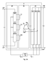
- FIG. 5 schematically illustrates an example of the first converter 20 of FIG. 2A and FIG. 2B , having three phase legs 301 i , 301 ii and 301 iii which are connected in series on the DC side between two poles of a DC connection 207 , 208 .
- the first converter 20 further has one AC connection per phase leg, denoted 210 i , 210 ii and 210 iii , respectively, the AC connection having two AC connection terminals.
- phase leg 301 When referring to any one (or all) of the phase legs 301 i , 301 ii and 301 iii , the common term phase leg 301 will be used; when referring to any one (or all) of the AC connections 210 i , 210 ii and 210 iii , the common term AC connection 210 is used, and so forth.
- Each phase leg 301 of FIG. 5 comprises a phase branch 303 having at least one converter cell.
- a phase branch 303 has two branch end connection terminals E at its respective ends.
- the phase branch 303 is connected (via end connection terminals E) in parallel with a series connection of a DC blocking capacitor 305 and the AC connection 210 .
- phase legs 301 between the two terminals of the DC connection 207 is such that a first connection point P1 in a phase leg is located between the first branch end terminal E and the capacitor 305 , while a second connection point P2 is located between the second branch end terminal E and the second terminal of AC connection 210 .
- the phase legs 301 are serially connected also via the AC connections 210 . This reduces requirements on valves, whereby e.g. a half bridge structure can be utilised.
- a serial phase unit needs a valve voltage rating corresponding to 2*V1/P. Compare this to a parallel converter, where each phase unit has to be able to withstand a voltage rating of 2*V1. Consequently, a factor P (3 in this example) lower total voltage rating is required in the series connected converter. On the other hand, the series connection requires three times higher current rating. However, voltage ratings have higher impact on cost than current rating, whereby component costs are reduced with a serial configuration.
- a second DC blocking capacitor 306 is provided between the AC connection 210 and the second connection point P2. This ensures that both terminals of the DC connection 207 are only connected via a capacitor 305 , 306 to the AC connection 210 , and thereby to the windings of the transformer. This implements DC blockage of both terminals of the DC connection 207 .
- the first converter 20 could for example include a passive filter, including for example a reactor and possibly further components, in series with the phase legs 301 and the poles of the DC connection 207 .
- a passive filter formed by a reactor 310 , is shown in FIG. 5 .
- a passive filter connected in series with the phase legs 301 and the poles of the DC connection 207 will be referred to as a DC line filter 310 , of which reactor 310 , referred to as DC line reactor 310 , forms one embodiment.
- reactors or other passive filter components may be included in series with each phase branch 303 and/or capacitor 305 .
- a phase branch 303 can be formed of a single converter cell, or of a series connection of two or more independently switchable converter cells arranged in a cascaded fashion.
- a cascade of series connected converter cells it is achieved that multiple voltage levels can be obtained at the AC side of a phase leg 301 , so that a more smooth synthesis of an AC-voltage can be obtained than if a phase branch 303 formed from a single converter cell is used.
- fewer filtering components and lower switching frequency will be required if the phase branch 303 comprises a cascade of converter cells than if a single converter cell is used as the phase branch 303 .
- the converter cells of a phase branch 303 can be half bridge converter cells, full bridge converter cells, or a combination of half bridge and full bridge converter cells.
- a half bridge converter cell comprises two series connected electric valve units 215 forming what may be referred to as a cell element, which is connected in parallel with a cell capacitor in a half bridge configuration.
- a full bridge converter cell comprises two such cell elements, both connected in parallel with a cell capacitor in a full bridge, or H bridge, fashion.
- an electric valve 215 can advantageously include a unidirectional switch, or switch for short, and an anti-parallel diode, where the unidirectional switch can be controlled to switch off, as well as to switch on.
- the voltage across a converter cell can take one of two (half bridge cell) or three (full bridge cell) different values.
- the two values are 0 and +Uc, or 0 and ⁇ Uc, (depending on which of two equivalent half bridge topologies is used), where Uc is the voltage across the cell capacitor.
- the three values are +Uc, 0 and ⁇ Uc.
- the switching state of a valve 215 of a converter cell can for example be controlled by sending a switch control signal (e.g. a Pulse Width Modulation (PWM) signal) to the switch of the valve 215 .
- PWM Pulse Width Modulation
- a drive unit is typically provided for sending such switch control signals.
- the converter shown in FIG. 5 could also be an example of the second converter of FIG. 2B .
- One difference from what is shown in that example is that the converter is connected to the second set 208 of DC terminals.
- FIG. 6A An example of an embodiment of a three-phase first converter 20 wherein a phase branch 303 comprises a single converter cell 400 is shown in FIG. 6A .
- the converter cells 400 of the first converter 20 shown in FIG. 6A are half bridge cells 400 .
- the converter cell 400 , the cell capacitor 405 and the two valves 215 each comprising a unidirectional switch and an anti-parallel diode, have been indicated by reference numerals.
- FIGS. 6B and 6C examples of different embodiments of a phase legs 301 having a phase branch 303 comprising a cascade 415 of independently switchable converter cells 400 are schematically shown.
- Two or more phase legs 301 as shown in FIGS. 6B and 6C could be series connected on the DC side to form a first converter 20 .
- the branch 303 comprises a cascade 415 of full bridge converter cells 400 .
- the branch 303 comprises a cascade 415 of half bridge converter cells 400 .
- a cascade 415 could include a series connection of any number N (N ⁇ 2) of half bridge converter cells 400 , or any number (N ⁇ 2) of full bridge converter cells 400 , or a combination of half bridge and full bridge converter cells 400 .
- Contact leads can be connected to a half bridge converter cell 400 according to two different topologies: either across the “top” valve, or across the “bottom” valve. Furthermore, the valves of a half bridge converter cell 400 can be of the same, or different, polarity. In a cascade 415 , half bridge cells 400 of the same, or different, topology, and/or of the same, or different, polarity, may be used.
- half bridge converter cells 400 of the same topology and same polarity in a phase branch 303 of a first converter 20 is often more cost efficient than to use full bridge converter cells 400 , or half bridge converter cells of different topology and/or different polarity, since fewer components are required, and a non-zero switching state of a first polarity is normally sufficient.
- a number of IGBTs can be connected in series, as shown in FIG. 4B for the second converter.
- phase branch 303 In order to improve the current withstanding property of a phase branch 303 , two or more cascades 415 could be connected in parallel to form a single phase branch 303 .
- the AC connection 210 i - iii of each phase leg 301 i - iii is respectively connected to a primary winding 17 i - iii of the multiphase transformer device 10 .
- An electric valve 215 is shown in FIGS. 6A-C to include a unidirectional switch and an anti-parallel diode, where the unidirectional switch can be controlled to switch off, as well as to switch on.
- a unidirectional switch could for example be an IGBT, an Integrated Gate-Commutated Thyristor (IGCT), a Gate Turn-Off thyristor (GTO), etc.
- the anti-parallel diode could be integrated in the switch, the switch thus being reverse conducting. Examples of such a reverse conducting switch, which on its own could provide the functionality of a valve 215 , are the reverse conducting IGCT and the bi-mode insulated gate transistor (BIGT).
- an electric valve 215 could comprise more than one switch, connected in series and/or in parallel and arranged to switch simultaneously, and/or more than one anti-parallel rectifying elements.
- connection point P2 has been shown to lie between the AC connection 210 and the end point E of the phase branch 303 towards which the unidirectional switches are capable of conducting current.
- connection point P2 could alternatively lie between the AC connection 210 and the end point E of the phase branch 303 towards which the unidirectional switches cannot conduct current.
- the capacitor 305 could be located on either side of AC the connection 210 in relation to the direction in which the unidirectional switches of the phase branch 303 is capable of conducting current.
- the AC voltage drop U 305 AC across a DC blocking capacitor 305 of a first converter 20 in operation will correspond to:
- U 305 AC I AC 2 ⁇ ⁇ ⁇ ⁇ f ⁇ ⁇ C 305 , ( 1 )
- I AC is the magnitude of the AC phase current
- C 305 is the capacitance of the DC blocking capacitor 305 .
- a suitable capacitance C 305 can for example be selected based on requirements on the AC impedance provided by the capacitor 305 in for example a ground fault scenario, in combination with capacitor manufacturing costs.
- the DC blocking capacitor 305 of a phase leg 301 should be designed to withstand at least the expected DC voltage U pkass 1 (often corresponding to
- AC used herein in the power transfer can be sinusoidal or square waveform.
Landscapes
- Engineering & Computer Science (AREA)
- Power Engineering (AREA)
- Rectifiers (AREA)
- Inverter Devices (AREA)
- Dc-Dc Converters (AREA)
Abstract
Description
U k =U k DC +Û ν AC sin(ωt+θ k)
where k indicates the kth phase leg, kε[1,P], P being the number of phases of the
UDC being the voltage between the DC connection terminals; Ûν AC is a desired peak AC voltage between the first and second connection points, t is time, ω is the desired angular frequency at the AC connection and θk is the desired phase angle.
where V1 is the voltage between the DC connection terminals and P is the number of phases of the
-
- number of
phase legs 301 i-iii in thefirst converter 20 series connected phases - turns ratio of the
multiphase transformer 10 device - AC voltage magnitude of the
first converter 20, which is defined by the modulation index of thefirst converter 20. By keeping the modulation index and thus AC voltage magnitude high, losses related to a lower current for a given active power level are reduced - AC voltage magnitude of the
second converter 21, which is defined by the modulation index of thesecond converter 21. By keeping the modulation index and thus AC voltage magnitude high, losses related to a lower current for a given active power level are reduced.
- number of
where IAC is the magnitude of the AC phase current and C305 is the capacitance of the
across the
Claims (20)
Applications Claiming Priority (1)
| Application Number | Priority Date | Filing Date | Title |
|---|---|---|---|
| PCT/EP2011/061172 WO2013004282A1 (en) | 2011-07-04 | 2011-07-04 | High voltage dc/dc converter |
Publications (2)
| Publication Number | Publication Date |
|---|---|
| US20140140104A1 US20140140104A1 (en) | 2014-05-22 |
| US9019732B2 true US9019732B2 (en) | 2015-04-28 |
Family
ID=44627777
Family Applications (1)
| Application Number | Title | Priority Date | Filing Date |
|---|---|---|---|
| US14/130,852 Active US9019732B2 (en) | 2011-07-04 | 2011-07-04 | High voltage DC/DC converter |
Country Status (4)
| Country | Link |
|---|---|
| US (1) | US9019732B2 (en) |
| EP (1) | EP2730016B1 (en) |
| CN (1) | CN103828211B (en) |
| WO (1) | WO2013004282A1 (en) |
Families Citing this family (19)
| Publication number | Priority date | Publication date | Assignee | Title |
|---|---|---|---|---|
| GB2520617B (en) * | 2013-10-22 | 2020-12-30 | Abb Schweiz Ag | RC-IGBT with freewheeling SiC diode |
| US9413221B1 (en) * | 2013-12-04 | 2016-08-09 | Google Inc. | Power conversion using a series of power converters |
| CN103633845A (en) * | 2013-12-19 | 2014-03-12 | 国家电网公司 | DC-DC (Direct-Current-Direct-Current) converter |
| WO2015156854A1 (en) * | 2014-04-09 | 2015-10-15 | Electranix Corporation | Multi-module dc-to-dc power transformation system |
| US9871437B2 (en) | 2014-07-10 | 2018-01-16 | University-Industry Foundation(UIF) | Fault current reduction structure of multi-level converter and apparatus using the fault current reduction structure |
| US10879805B2 (en) | 2015-09-22 | 2020-12-29 | Infineon Technologies Austria Ag | System and method for a switched-mode power supply having a transformer with a plurality of primary windings |
| US10608545B2 (en) | 2015-10-05 | 2020-03-31 | Resilient Power Systems, LLC | Power management utilizing synchronous common coupling |
| US9780682B2 (en) | 2015-10-05 | 2017-10-03 | Resilient Power Systems, LLC | Power management utilizing synchronous common coupling |
| KR102320302B1 (en) * | 2016-06-10 | 2021-11-01 | 엔티엔 가부시키가이샤 | power factor correction device |
| GB201621148D0 (en) * | 2016-12-13 | 2017-01-25 | Isotek Electronics Ltd | A subsea DC to DC coltage converter and a system for supplying power to a remote electrical device |
| EP3352354B1 (en) * | 2017-01-19 | 2019-12-18 | General Electric Technology GmbH | A voltage source converter |
| KR102653533B1 (en) * | 2017-05-15 | 2024-04-02 | 다이너파워 컴퍼니 엘엘씨 | DC/DC converter and its converter control |
| WO2019120468A1 (en) * | 2017-12-18 | 2019-06-27 | Abb Schweiz Ag | Mmc phase leg and method for control thereof |
| US11228246B1 (en) | 2018-03-09 | 2022-01-18 | Vicor Corporation | Three-phase AC to DC isolated power conversion with power factor correction |
| WO2019238239A1 (en) | 2018-06-15 | 2019-12-19 | Abb Schweiz Ag | Series modular dc to dc converter |
| CN111446860B (en) * | 2019-01-16 | 2021-09-21 | 台达电子企业管理(上海)有限公司 | DC/DC converter and control method thereof |
| CN111446861B (en) | 2019-01-16 | 2021-02-26 | 台达电子企业管理(上海)有限公司 | DC/DC converter and control method thereof |
| GB201901027D0 (en) | 2019-01-25 | 2019-03-13 | Rolls Royce Plc | Voltage converter |
| FR3096849A1 (en) * | 2019-05-28 | 2020-12-04 | Ecole Centrale De Lyon | DC / DC voltage converter including a transformer |
Citations (14)
| Publication number | Priority date | Publication date | Assignee | Title |
|---|---|---|---|---|
| WO2000062409A1 (en) | 1999-03-29 | 2000-10-19 | Abb Ab | A vsc-converter |
| US20020024824A1 (en) | 2000-08-09 | 2002-02-28 | Harry Reinold | High-voltage DC/DC converter |
| WO2004082115A1 (en) | 2003-03-14 | 2004-09-23 | Abb Technology Ltd | A vsc converter and a method |
| US20050017699A1 (en) * | 2003-07-24 | 2005-01-27 | Stanley Gerald A. | Series interleaved boost converter power factor correcting power supply |
| US20050047183A1 (en) * | 2002-08-22 | 2005-03-03 | Nissin Electric Co., Ltd. | DC-DC converter |
| EP1589648A2 (en) | 2004-04-22 | 2005-10-26 | Ask Industries S.p.A. | A DC/DC three-phase converter |
| WO2007028349A1 (en) | 2005-09-09 | 2007-03-15 | Siemens Aktiengesellschaft | Device for electron energy transfer |
| US7269037B2 (en) * | 2002-04-22 | 2007-09-11 | Siemens Aktiengesellschaft | Power supply with a direct converter |
| CN101707443A (en) | 2009-11-20 | 2010-05-12 | 中国电力科学研究院 | Novel electric power electric transformer |
| US20100128498A1 (en) | 2007-07-25 | 2010-05-27 | Danmarks Tekniske Universitet | Switch mode pulse width modulated dc-dc converter with multiple power transformers |
| WO2010088969A1 (en) | 2009-02-09 | 2010-08-12 | Areva T&D Uk Limited | Converter |
| CN101867304A (en) | 2010-06-21 | 2010-10-20 | 华南理工大学 | Secondary side rectification circuit using high frequency three-phase transformer DC converter |
| US20100328968A1 (en) | 2009-06-24 | 2010-12-30 | Stmicroelectronics S.R.I. | Multi-phase resonant converter and method of controlling it |
| WO2011029566A1 (en) | 2009-09-08 | 2011-03-17 | Converteam Technology Ltd | Power transmission and distribution systems |
Family Cites Families (1)
| Publication number | Priority date | Publication date | Assignee | Title |
|---|---|---|---|---|
| US8837176B2 (en) * | 2009-08-03 | 2014-09-16 | Alstom Technology, Ltd. | Converter with reactive power compensation |
-
2011
- 2011-07-04 US US14/130,852 patent/US9019732B2/en active Active
- 2011-07-04 WO PCT/EP2011/061172 patent/WO2013004282A1/en not_active Ceased
- 2011-07-04 CN CN201180072073.6A patent/CN103828211B/en active Active
- 2011-07-04 EP EP11728864.7A patent/EP2730016B1/en active Active
Patent Citations (17)
| Publication number | Priority date | Publication date | Assignee | Title |
|---|---|---|---|---|
| US6519169B1 (en) * | 1999-03-29 | 2003-02-11 | Abb Ab | Multiphase inverter with series of connected phase legs |
| WO2000062409A1 (en) | 1999-03-29 | 2000-10-19 | Abb Ab | A vsc-converter |
| US20020024824A1 (en) | 2000-08-09 | 2002-02-28 | Harry Reinold | High-voltage DC/DC converter |
| EP1184963A2 (en) | 2000-08-09 | 2002-03-06 | ABB Research Ltd. | DC-DC high voltage converter |
| US7269037B2 (en) * | 2002-04-22 | 2007-09-11 | Siemens Aktiengesellschaft | Power supply with a direct converter |
| US20050047183A1 (en) * | 2002-08-22 | 2005-03-03 | Nissin Electric Co., Ltd. | DC-DC converter |
| WO2004082115A1 (en) | 2003-03-14 | 2004-09-23 | Abb Technology Ltd | A vsc converter and a method |
| US20050017699A1 (en) * | 2003-07-24 | 2005-01-27 | Stanley Gerald A. | Series interleaved boost converter power factor correcting power supply |
| EP1589648A2 (en) | 2004-04-22 | 2005-10-26 | Ask Industries S.p.A. | A DC/DC three-phase converter |
| WO2007028349A1 (en) | 2005-09-09 | 2007-03-15 | Siemens Aktiengesellschaft | Device for electron energy transfer |
| US20080205093A1 (en) * | 2005-09-09 | 2008-08-28 | Siemens Aktiengesellschaft | Apparatus for Electrical Power Transmission |
| US20100128498A1 (en) | 2007-07-25 | 2010-05-27 | Danmarks Tekniske Universitet | Switch mode pulse width modulated dc-dc converter with multiple power transformers |
| WO2010088969A1 (en) | 2009-02-09 | 2010-08-12 | Areva T&D Uk Limited | Converter |
| US20100328968A1 (en) | 2009-06-24 | 2010-12-30 | Stmicroelectronics S.R.I. | Multi-phase resonant converter and method of controlling it |
| WO2011029566A1 (en) | 2009-09-08 | 2011-03-17 | Converteam Technology Ltd | Power transmission and distribution systems |
| CN101707443A (en) | 2009-11-20 | 2010-05-12 | 中国电力科学研究院 | Novel electric power electric transformer |
| CN101867304A (en) | 2010-06-21 | 2010-10-20 | 华南理工大学 | Secondary side rectification circuit using high frequency three-phase transformer DC converter |
Also Published As
| Publication number | Publication date |
|---|---|
| EP2730016A1 (en) | 2014-05-14 |
| WO2013004282A1 (en) | 2013-01-10 |
| EP2730016B1 (en) | 2017-01-25 |
| CN103828211A (en) | 2014-05-28 |
| US20140140104A1 (en) | 2014-05-22 |
| CN103828211B (en) | 2017-07-14 |
Similar Documents
| Publication | Publication Date | Title |
|---|---|---|
| US9019732B2 (en) | High voltage DC/DC converter | |
| US9748848B2 (en) | Modular multilevel DC/DC converter for HVDC applications | |
| US10608522B2 (en) | Electrical circuit with auxiliary voltage source for zero-voltage switching in DC-DC converter under all load conditions | |
| US8824179B2 (en) | Soft-switching high voltage power converter | |
| US10637371B2 (en) | Interface arrangement between an alternating current power system and a direct current power system with control of converter valve for fault protection | |
| US9705406B2 (en) | Modular multi-level DC-DC converter for HVDC applications | |
| US9007792B2 (en) | Arrangement for transmitting power between a DC power line and an AC power line | |
| US20130170255A1 (en) | Apparatus for controlling the electric power transmission in a hvdc power transmission system | |
| US9461555B2 (en) | HVDC series current source converter | |
| WO2013185825A1 (en) | Multiline hvdc station with mmc and csc inputs | |
| KR102235397B1 (en) | Power converting apparatus having scott transformer | |
| US10873254B2 (en) | Electrical circuit for zero-voltage soft-switching in DC-DC converter under all load conditions | |
| US9461538B2 (en) | DC/DC converter | |
| WO2013149633A9 (en) | A power converter | |
| US20190068081A1 (en) | Converter | |
| US20110080758A1 (en) | Plant for transmitting electric power | |
| WO2013013858A1 (en) | An apparatus for controlling the electric power transmission in a hvdc power transmission system | |
| CN106797124B (en) | AC troubleshootings are arranged | |
| US20180166877A1 (en) | Voltage source converter | |
| US20160134200A1 (en) | Power converter with oil filled reactors | |
| US10958190B2 (en) | Multi-level voltage sourced converter |
Legal Events
| Date | Code | Title | Description |
|---|---|---|---|
| AS | Assignment |
Owner name: ABB TECHNOLOGY AG, SWITZERLAND Free format text: ASSIGNMENT OF ASSIGNORS INTEREST;ASSIGNORS:NORRGA, STAFFAN;PAPASTERGIOU, KONSTANTINOS;SUBRAMANIAN, SASITHARAN;AND OTHERS;SIGNING DATES FROM 20131213 TO 20140107;REEL/FRAME:032146/0357 |
|
| FEPP | Fee payment procedure |
Free format text: PAYOR NUMBER ASSIGNED (ORIGINAL EVENT CODE: ASPN); ENTITY STATUS OF PATENT OWNER: LARGE ENTITY |
|
| STCF | Information on status: patent grant |
Free format text: PATENTED CASE |
|
| AS | Assignment |
Owner name: ABB SCHWEIZ AG, SWITZERLAND Free format text: MERGER;ASSIGNOR:ABB TECHNOLOGY LTD.;REEL/FRAME:040622/0128 Effective date: 20160509 |
|
| MAFP | Maintenance fee payment |
Free format text: PAYMENT OF MAINTENANCE FEE, 4TH YEAR, LARGE ENTITY (ORIGINAL EVENT CODE: M1551); ENTITY STATUS OF PATENT OWNER: LARGE ENTITY Year of fee payment: 4 |
|
| AS | Assignment |
Owner name: ABB POWER GRIDS SWITZERLAND AG, SWITZERLAND Free format text: ASSIGNMENT OF ASSIGNORS INTEREST;ASSIGNOR:ABB SCHWEIZ AG;REEL/FRAME:052916/0001 Effective date: 20191025 |
|
| AS | Assignment |
Owner name: HITACHI ENERGY SWITZERLAND AG, SWITZERLAND Free format text: CHANGE OF NAME;ASSIGNOR:ABB POWER GRIDS SWITZERLAND AG;REEL/FRAME:058666/0540 Effective date: 20211006 |
|
| AS | Assignment |
Owner name: ABB SCHWEIZ AG, SWITZERLAND Free format text: CORRECTIVE ASSIGNMENT TO CORRECT THE CONVEYIGN PARTY "ABB TECHNOLOGY LTD."SHOULD READ"ABB TECHNOLOGY AG" PREVIOUSLY RECORDED AT REEL: 040622 FRAME: 0128. ASSIGNOR(S) HEREBY CONFIRMS THE MERGER;ASSIGNOR:ABB TECHNOLOGY AG;REEL/FRAME:059928/0001 Effective date: 20160509 |
|
| MAFP | Maintenance fee payment |
Free format text: PAYMENT OF MAINTENANCE FEE, 8TH YEAR, LARGE ENTITY (ORIGINAL EVENT CODE: M1552); ENTITY STATUS OF PATENT OWNER: LARGE ENTITY Year of fee payment: 8 |
|
| AS | Assignment |
Owner name: HITACHI ENERGY LTD, SWITZERLAND Free format text: MERGER;ASSIGNOR:HITACHI ENERGY SWITZERLAND AG;REEL/FRAME:065549/0576 Effective date: 20231002 |