US9015095B2 - Neural network designing method and digital-to-analog fitting method - Google Patents
Neural network designing method and digital-to-analog fitting method Download PDFInfo
- Publication number
- US9015095B2 US9015095B2 US13/650,928 US201213650928A US9015095B2 US 9015095 B2 US9015095 B2 US 9015095B2 US 201213650928 A US201213650928 A US 201213650928A US 9015095 B2 US9015095 B2 US 9015095B2
- Authority
- US
- United States
- Prior art keywords
- oscillating
- rnn
- cos
- output
- sin
- Prior art date
- Legal status (The legal status is an assumption and is not a legal conclusion. Google has not performed a legal analysis and makes no representation as to the accuracy of the status listed.)
- Active, expires
Links
Images
Classifications
-
- G06N3/0445—
-
- G—PHYSICS
- G06—COMPUTING; CALCULATING OR COUNTING
- G06N—COMPUTING ARRANGEMENTS BASED ON SPECIFIC COMPUTATIONAL MODELS
- G06N3/00—Computing arrangements based on biological models
- G06N3/02—Neural networks
- G06N3/04—Architecture, e.g. interconnection topology
- G06N3/044—Recurrent networks, e.g. Hopfield networks
-
- G—PHYSICS
- G06—COMPUTING; CALCULATING OR COUNTING
- G06N—COMPUTING ARRANGEMENTS BASED ON SPECIFIC COMPUTATIONAL MODELS
- G06N3/00—Computing arrangements based on biological models
- G06N3/02—Neural networks
- G06N3/04—Architecture, e.g. interconnection topology
- G06N3/049—Temporal neural networks, e.g. delay elements, oscillating neurons or pulsed inputs
Definitions
- the embodiments discussed herein are related to a neural network designing method, a digital-to-analog fitting method, and a computer-readable storage medium having stored therein a program for causing a computer to execute a neural network designing process.
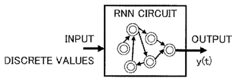
- a RNN (Recurrent Neural Network) is a kind of neural network developed for applications to robot operations and the like.
- the RNN is not only applicable to robot operations, but is also applicable to physical models of various electronic apparatuses including a pedometer, a speech analysis apparatus, and the like.
- the RNN itself is proposed in Fumio Nagashima, “A Bilinear Time Delay Neural Network Model for a Robot Software System”, Journal of Robotics Society of Japan, Vol. 24, No. 6, pp. 54-64, 2006, for example.
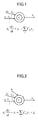
- the RNN is a network including a neuron and connections, and may be expressed by a relational formula of the neuron and input and output connections, as illustrated in FIG. 1 .
- ⁇ i denotes a delay parameter
- y i and y j denote neuron state quantities
- C ij denotes a weighting coefficient
- t denotes the time
- the neuron state quantity y i may be regarded as being the same as the neuron.
- FIG. 2 illustrates that, in addition to the structure illustrated in FIG. 1 , a value g i is input to the neuron y i , where the value g i is a value obtained by other than a neuron of a RNN circuit.
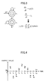
- FIG. 3 is a diagram for explaining an example of the RNN circuit.
- the RNN circuit illustrated in FIG. 3 includes two (2) neurons and five (5) connections.
- ⁇ i 1, and a value “1” indicated beside the connection denotes the weighting coefficient.
- a top right portion of FIG. 3 illustrates a differential equation of the RNN circuit, and a bottom right portion of FIG. 3 illustrates a solution that is obtained when the differential equation is solved. Solving this differential equation may physically correspond to obtaining a locus (or moving distance) y 1 (t) when an acceleration g(t) is given, for example.
- the RNN circuit illustrated in FIG. 3 may obtain the locus from the acceleration, and it may be seen that this RNN circuit employs an analog concept since the input and output of the RNN circuit are represented as a function of continuous time t.
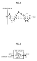
- an acceleration sensor is configured to output a value for every unit time, and output values are discrete (or digital) values, as illustrated in FIG. 4 , for example.
- FIG. 4 is a diagram illustrating an example of the output values of the acceleration sensor.
- the ordinate indicates the output value of the acceleration sensor in arbitrary units
- the abscissa indicates the time in arbitrary units.
- FIG. 4 illustrates output values y 1 to y 10 at times t 0 to t 10 .
- FIG. 5 is a diagram illustrating an example of the analog curve fitted to the discrete values.
- the analog curve fitted to the discrete values may be created by connecting each of the discrete values by line segments, or by fitting a spline curve to the discrete values.
- FIG. 6 is a diagram schematically illustrating the RNN circuit that outputs the fitting curve in response to the discrete values input thereto.
- the locus may be output from the discrete output values of the acceleration sensor.
- the curve that connects each of the discrete points by the line segments cannot be differentiated at the discrete points.
- all curves that are obtained as the output of the RNN circuit can be differentiated at the discrete points.
- the curve that connects each of the discrete values by the line segments is not obtainable as an output of the RNN circuit.
- the spline curve connects each of the discrete points by a polynomial curve, and the polynomial curve may be output from the RNN circuit.
- the polynomial curve is modified between the discrete points, the weighting coefficient of each connection of the RNN circuit need to be modified between the discrete points, to thereby make the processing extremely complex.
- a neural network designing method may include a forming procedure causing a computer to form a RNN (Recurrent Neural Network) circuit to include a plurality of oscillating RNN circuits configured to output natural oscillations, and an adding circuit configured to obtain a sum of outputs of the plurality of oscillating RNN circuits; and a computing procedure causing the computer to input discrete data to the plurality of oscillating RNN circuits, in order to compute a fitting curve with respect to the discrete data output from the adding circuit.
- a forming procedure causing a computer to form a RNN (Recurrent Neural Network) circuit to include a plurality of oscillating RNN circuits configured to output natural oscillations, and an adding circuit configured to obtain a sum of outputs of the plurality of oscillating RNN circuits
- a computing procedure causing the computer to input discrete data to the plurality of oscillating RNN circuits, in order to compute a fitting curve with respect to the discrete data output from the adding circuit.
- FIG. 1 is a diagram for explaining a relational formula of a neuron and input and output connections
- FIG. 2 is a diagram for explaining an expansion of the relational formula illustrated in FIG. 1 ;
- FIG. 3 is a diagram for explaining an example of a RNN circuit
- FIG. 4 is a diagram illustrating an example of output values of an acceleration sensor
- FIG. 5 is a diagram illustrating an example of an analog curve fitted to the discrete values
- FIG. 6 is a diagram schematically illustrating a RNN circuit that outputs a fitting curve in response to the discrete values input thereto;
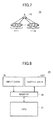
- FIG. 7 is a diagram illustrating an example of an RNN circuit used in one embodiment
- FIG. 8 is a block diagram for explaining a neural network designing method in one embodiment, for a case in which the fitting curve is output based on the discrete values that are input;
- FIG. 9 is a diagram illustrating an example of the discrete values
- FIG. 10 is a diagram illustrating an example of a fitting curve of the discrete values
- FIG. 11 is a diagram illustrating an example of an oscillating RNN circuit
- FIG. 12 is a diagram illustrating an example of the RNN circuit for outputting the fitting curve.
- FIG. 13 is a block diagram illustrating an example of a computer system.
- a RNN Recurrent Neural Network
- a RNN circuit that is a design target, is formed to include a plurality of oscillating RNN circuits outputting natural oscillations, and a adding circuit obtaining a sum of the outputs of the plurality of oscillating RNN circuits.
- Discrete data may be input to the plurality of oscillating RNN circuits, in order to compute a fitting curve with respect to the discrete data output from the adding circuit.
- the fitting curve illustrated in FIG. 6 may be realized and this RNN circuit may output a fitting curve based on discrete values input thereto, the fitting curve preferably satisfies an averaging process represented by the following formula (1).
- the present inventor conceived that, as long as the conditions of the formula (1) above are satisfied, the integral of the fitting curve y(t) (that is, an average of the fitting curve y(t)) may be obtained by adding original discrete points (that is, averaging the discrete points), even when the integral of the fitting curve y(t) is not computed directly.
- the present inventor conceived that the amount of computation is greatly reduced, the load of the computation is reduced, and the computation time is reduced, by obtaining the integral of the fitting curve y(t) from the sum of the original discrete points.
- the RNN circuit is formed to include a plurality of oscillating RNN circuits outputting natural oscillations, and a adding circuit obtaining a sum of the outputs of the plurality of oscillating RNN circuits, in order to output a fitting curve with respect to the original discrete points, satisfying the averaging process represented by the formula (1).
- FIG. 7 is a diagram illustrating an example of a RNN circuit used in one embodiment.
- a RNN circuit 10 includes a plurality of oscillating RNN circuits 11 - 1 through 11 -N (N is a natural number greater than or equal to 2) configured to output natural oscillations, and a adding circuit 12 configured to obtain a sum of the outputs of the plurality of oscillating RNN circuits 11 - 1 through 11 -N.
- FIG. 8 is a block diagram for explaining the neural network designing method in one embodiment, for a case in which the fitting curve is output based on the discrete values that are input.
- an input data IN is input to a PC (Personal Computer) 20
- an output data OUT is output from the PC 20 .
- the PC 20 is an example of a general-purpose computer.
- the input data IN may be a discrete value (or discrete data) output from an acceleration sensor (not illustrated), for example.
- the output data OUT may be an acceleration fitting curve or a locus curve generated with respect to the input data IN, by the RNN circuit 10 illustrated in FIG. 7 , or by a combination of the RNN circuit 10 and another RNN circuit such as that illustrated in FIG.
- the PC 20 includes a CPU (Central Processing Unit) 21 that is an example of a processor, and a memory 22 that is an example of a storage unit.
- the input data IN input to the PC 20 may be stored in the memory 22 as an input data file.
- the output data OUT output from the PC 20 may be stored in the memory 22 as an output data file.
- the output of the RNN circuit 10 may be input to the other RNN circuit, for example.
- the memory 22 may store the input data IN to the PC 20 , the output data OUT from the PC 20 , and a program of the RNN circuit.
- the program of the RNN circuit causes the CPU 21 to execute a process of the RNN circuit 10 , or a process of the combination of the RNN circuit 10 and the other RNN circuit.
- the CPU 21 computes the acceleration fitting curve or the locus curve, based on the program and the input data IN stored in the memory 22 .
- the acceleration fitting curve or the locus curve that is computed is stored in the memory 22 to be output as the output data OUT.
- the output data OUT (locus curve) may be input to a robot (not illustrated), for example, in order to cause the robot to move along the locus curve.
- a data length may be set when inputting the input data IN, that is, the discrete data, to the PC 20 .
- the data length of the input data IN is set to an even number 2n greater than the actual data length 2n ⁇ 1.
- the data length is set to the even number 2n that is greater than the actual data length 2n ⁇ 1.
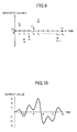
- FIG. 9 is a diagram illustrating an example of the discrete values of the discrete data.
- the ordinate indicates the discrete value in arbitrary units
- the abscissa indicates the time in arbitrary units.
- ⁇ (x) denotes a trigamma function that is defined by a second derivative of a logarithm of a gamma function.
- a 0 , a 1 , . . . , a 2n-1 , b 1 , . . . , b 2n-1 obtained from the formulas (2) are fixed values independent of the time t. These fixed values a 0 , a 1 , . . . , a 2n-1 , b 1 , b 2n-1 may be used to define the fitting curve according to the following formula (3).
- cos(q ⁇ t/n) and sin(q ⁇ t/n) are oscillating functions output the plurality of oscillating RNN circuits 11 - 1 through 11 -N.
- the fitting curve may be obtained by combining these oscillating functions.
- it may be confirmed from the following transformation formula (4) that the fitting curve defined by the formula (3) satisfies the averaging process represented by the formula (1).
- FIG. 10 is a diagram illustrating an example of the fitting curve of the discrete values.
- the ordinate indicates the output value in arbitrary units
- the abscissa indicates the time in arbitrary units.
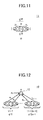
- FIG. 11 is a diagram illustrating an example of an oscillating RNN circuit.
- the following formulas (5) correspond to a representation of a process of an oscillating RNN circuit 11 illustrated in FIG. 11 by differential equations, and the following formulas (6) correspond to solutions of the differential equations, output from the oscillating RNN circuit 11 .
- the oscillating RNN circuit 11 illustrated in FIG. 11 may obtain the functions cos(q ⁇ t/n) and sin(q ⁇ t/n).
- FIG. 12 is a diagram illustrating an example of the RNN circuit for outputting the fitting curve defined by the formula (3) above.
- the RNN circuit 10 illustrated in FIG. 12 obtains the sum of the outputs of 2n ⁇ 1 (n is a natural number greater than or equal to 2) oscillating RNN circuits 11 - 1 through 11 -(2n ⁇ 1) by the adding circuit 12 , in order to compute the fitting curve with respect to the input discrete data.
- the values of a 0 , a 1 , . . . , a 2n-1 , b 1 , . . . , b 2n-1 in the formulas (2) above, that are obtained from the discrete data y 0 0, y 1 , . . .
- the fitting curve may be output based on the input discrete data, and the fitting curve that is output may satisfy the averaging process represented by the formula (1) above, for example.
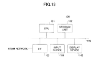
- FIG. 13 is a block diagram illustrating an example of a computer system.
- a computer system 100 illustrated in FIG. 13 includes a CPU 101 , a storage unit 102 , an interface (I/F) 103 , an input device 104 , and a display device 105 that are connected via a bus 106 .
- the CPU 101 may execute a program stored in the storage unit 102 and control the entire computer system 100 .
- the storage unit 102 may be formed by a semiconductor memory device, a magnetic recording medium, an optical recording medium, a magneto-optic recording medium, and the like.
- the storage unit 102 may store the program described above and various kinds of data.
- the storage unit 102 may also function as a temporary memory to temporarily store intermediate results and computation results of the computations executed by the CPU 101 .
- the storage unit 102 may further store the input data to the computer system 100 and the output data from the computer system 100 .
- the CPU 101 and the storage unit 102 respectively correspond to the CPU 21 and the memory 22 illustrated in FIG
- the I/F 103 may receive the program and the data to be stored in the storage unit 102 , via a network (not illustrated).
- the input device 104 may be formed by a keyboard or the like.
- the display device 105 may be formed by a display unit, a display panel, or the like.
- the input device 104 and the display device 105 may be formed by an input and output device having the functions of both the input device 104 and the display device 105 , such as a touch-screen panel integrally having an input device and a display device.
- the CPU 101 may execute the program stored in the storage unit 102 in order to cause the computer system 100 to function as an apparatus for designing a neural network.
- the program may cause the CPU 101 to execute procedures of at least a neural network designing process, and this program may be stored in a suitable non-transitory computer-readable storage medium, such as the storage unit 102 .
- the program causes the CPU 101 to execute a process for forming a RNN circuit that includes at least the plurality of oscillating RNN circuits 11 - 1 through 11 -N (or 11 -(2n ⁇ 1)) to output natural oscillations, and the adding circuit 12 to obtain the sum of the outputs of the plurality of oscillating RNN circuits 11 - 1 through 11 -N (or 11 -(2n ⁇ 1)), as illustrated in FIG. 7 or FIG. 12 .
- the program may cause the CPU 101 to execute a process of the RNN circuit 10 that includes at least the plurality of oscillating RNN circuits 11 - 1 through 11 -N (or 11 -(2n ⁇ 1)) to output natural oscillations, and the adding circuit 12 to obtain the sum of the outputs of the plurality of oscillating RNN circuits 11 - 1 through 11 -N (or 11 -(2n ⁇ 1)), as illustrated in FIG. 7 or FIG. 12 , or a process of a combination of the RNN circuit 10 and another RNN circuit such as that illustrated in FIG. 3 .
- a program that causes the CPU 101 to execute at least the process of the RNN circuit 10 to generate the fitting curve of the discrete values may be provided as a plug-in with respect to the program that causes the CPU 101 to execute the procedures of the neural network designing process.
- the program that causes the CPU 101 to execute at least the process of the RNN circuit 10 may cause the CPU 101 to function as a circuit or an apparatus for performing a digital-to-analog fitting method (or process) to output an analog curve fitted to the discrete values.
- the output (fitting curve) of the RNN circuit 10 may be displayed on the display device 105 , or may be output via the I/F 103 to the outside of the computer system 100 .
- the application of the RNN circuit to the robot is described.
- the RNN circuit designed by the disclosed method is not limited to the application to driving circuits and the like of robots, and may be applied to various physical models of electronic apparatuses, control circuits, speech analysis circuits, and the like.
Landscapes
- Engineering & Computer Science (AREA)
- Theoretical Computer Science (AREA)
- Physics & Mathematics (AREA)
- General Health & Medical Sciences (AREA)
- Computing Systems (AREA)
- Biomedical Technology (AREA)
- Biophysics (AREA)
- Computational Linguistics (AREA)
- Data Mining & Analysis (AREA)
- Evolutionary Computation (AREA)
- Life Sciences & Earth Sciences (AREA)
- Molecular Biology (AREA)
- Artificial Intelligence (AREA)
- General Engineering & Computer Science (AREA)
- General Physics & Mathematics (AREA)
- Mathematical Physics (AREA)
- Software Systems (AREA)
- Health & Medical Sciences (AREA)
- Complex Calculations (AREA)
- Feedback Control In General (AREA)
Applications Claiming Priority (2)
| Application Number | Priority Date | Filing Date | Title |
|---|---|---|---|
| JP2012013485 | 2012-01-25 | ||
| JP2012-013485 | 2012-01-25 |
Publications (2)
| Publication Number | Publication Date |
|---|---|
| US20130268473A1 US20130268473A1 (en) | 2013-10-10 |
| US9015095B2 true US9015095B2 (en) | 2015-04-21 |
Family
ID=49267972
Family Applications (1)
| Application Number | Title | Priority Date | Filing Date |
|---|---|---|---|
| US13/650,928 Active 2033-06-27 US9015095B2 (en) | 2012-01-25 | 2012-10-12 | Neural network designing method and digital-to-analog fitting method |
Country Status (2)
| Country | Link |
|---|---|
| US (1) | US9015095B2 (ja) |
| JP (1) | JP5888013B2 (ja) |
Cited By (2)
| Publication number | Priority date | Publication date | Assignee | Title |
|---|---|---|---|---|
| US20150178245A1 (en) * | 2013-12-20 | 2015-06-25 | Fujitsu Limited | Information processing apparatus and method |
| US10853724B2 (en) | 2017-06-02 | 2020-12-01 | Xerox Corporation | Symbolic priors for recurrent neural network based semantic parsing |
Families Citing this family (1)
| Publication number | Priority date | Publication date | Assignee | Title |
|---|---|---|---|---|
| JP6834180B2 (ja) * | 2016-06-01 | 2021-02-24 | 富士通株式会社 | 歩数学習方法、歩数学習プログラム、情報処理装置、歩行データ処理方法、歩行データ処理プログラムおよび歩行データ処理装置 |
Citations (7)
| Publication number | Priority date | Publication date | Assignee | Title |
|---|---|---|---|---|
| JPH07234697A (ja) | 1994-02-08 | 1995-09-05 | At & T Corp | 音声信号の符号化方法 |
| JPH0973440A (ja) | 1995-09-06 | 1997-03-18 | Fujitsu Ltd | コラム構造の再帰型ニューラルネットワークによる時系列トレンド推定システムおよび方法 |
| JP2000310997A (ja) | 1999-03-09 | 2000-11-07 | Matsushita Electric Ind Co Ltd | 連結型音声合成のための単位重複領域の識別方法および連結型音声合成方法 |
| US20040162644A1 (en) * | 2003-02-19 | 2004-08-19 | Fuji Jukogyo Kabushiki Kaisha | Vehicle motion model generating device and method for generating vehicle motion model |
| US20050197985A1 (en) * | 2000-07-04 | 2005-09-08 | Jun Tani | Information processing apparatus and method, and recording medium |
| US20100010948A1 (en) * | 2008-07-09 | 2010-01-14 | Masato Ito | Learning Device, Learning Method, and Program |
| US20130041859A1 (en) * | 2011-08-11 | 2013-02-14 | Greenray Industries, Inc. | Neural network frequency control |
-
2012
- 2012-03-08 JP JP2012052328A patent/JP5888013B2/ja active Active
- 2012-10-12 US US13/650,928 patent/US9015095B2/en active Active
Patent Citations (10)
| Publication number | Priority date | Publication date | Assignee | Title |
|---|---|---|---|---|
| JPH07234697A (ja) | 1994-02-08 | 1995-09-05 | At & T Corp | 音声信号の符号化方法 |
| US5517595A (en) | 1994-02-08 | 1996-05-14 | At&T Corp. | Decomposition in noise and periodic signal waveforms in waveform interpolation |
| JPH0973440A (ja) | 1995-09-06 | 1997-03-18 | Fujitsu Ltd | コラム構造の再帰型ニューラルネットワークによる時系列トレンド推定システムおよび方法 |
| US5956702A (en) | 1995-09-06 | 1999-09-21 | Fujitsu Limited | Time-series trend estimating system and method using column-structured recurrent neural network |
| JP2000310997A (ja) | 1999-03-09 | 2000-11-07 | Matsushita Electric Ind Co Ltd | 連結型音声合成のための単位重複領域の識別方法および連結型音声合成方法 |
| US6202049B1 (en) | 1999-03-09 | 2001-03-13 | Matsushita Electric Industrial Co., Ltd. | Identification of unit overlap regions for concatenative speech synthesis system |
| US20050197985A1 (en) * | 2000-07-04 | 2005-09-08 | Jun Tani | Information processing apparatus and method, and recording medium |
| US20040162644A1 (en) * | 2003-02-19 | 2004-08-19 | Fuji Jukogyo Kabushiki Kaisha | Vehicle motion model generating device and method for generating vehicle motion model |
| US20100010948A1 (en) * | 2008-07-09 | 2010-01-14 | Masato Ito | Learning Device, Learning Method, and Program |
| US20130041859A1 (en) * | 2011-08-11 | 2013-02-14 | Greenray Industries, Inc. | Neural network frequency control |
Non-Patent Citations (3)
| Title |
|---|
| "Global Asymptotical Stability of Recurrent Neural Networks With Multiple Discrete Delays and Distributed Delays" Jinde Cao, Kun Yuan, and Han-Xiong Li Manuscript received Mar. 14, 2005; revised Feb. 1, 2006. Digital Object Identifier 10.1109/TNN.2006.881488; 1045-9227/$20.00 © 2006 IEEE. * |
| Fumio Nagashima; "A Bilinear Time Delay Neural Network Model for a Robot Software System", Journal of Robotics Society of Japan, vol. 24, No. 6, pp. 54-64 (2006). |
| Global Exponential Periodicity of a Class of Recurrent Neural Networks With Oscillating Parameters and Time-Varying Delays Boshan Chen and Jun Wang, Senior Member, IEEE IEEE Transactions on Neural Networks, vol. 16, No. 6, Nov. 2005. * |
Cited By (3)
| Publication number | Priority date | Publication date | Assignee | Title |
|---|---|---|---|---|
| US20150178245A1 (en) * | 2013-12-20 | 2015-06-25 | Fujitsu Limited | Information processing apparatus and method |
| US9798699B2 (en) * | 2013-12-20 | 2017-10-24 | Fujitsu Limited | Apparatus and method for system error monitoring |
| US10853724B2 (en) | 2017-06-02 | 2020-12-01 | Xerox Corporation | Symbolic priors for recurrent neural network based semantic parsing |
Also Published As
| Publication number | Publication date |
|---|---|
| JP5888013B2 (ja) | 2016-03-16 |
| JP2013175143A (ja) | 2013-09-05 |
| US20130268473A1 (en) | 2013-10-10 |
Similar Documents
| Publication | Publication Date | Title |
|---|---|---|
| Wallstedt et al. | An evaluation of explicit time integration schemes for use with the generalized interpolation material point method | |
| US7529652B1 (en) | Method for modelling and analyzing linear time invariant systems with time delays | |
| Arenas et al. | A nonstandard numerical scheme of predictor–corrector type for epidemic models | |
| US8712753B1 (en) | Method for modeling and analyzing linear time invariant systems with time delays | |
| Etman et al. | First-order sequential convex programming using approximate diagonal QP subproblems | |
| US20210182720A1 (en) | Information processing device, pubo solver, information processing method and non-transitory storage medium | |
| Higueras et al. | Optimized strong stability preserving IMEX Runge–Kutta methods | |
| Kang et al. | Algorithms of data generation for deep learning and feedback design: A survey | |
| US9015095B2 (en) | Neural network designing method and digital-to-analog fitting method | |
| US20160063142A1 (en) | Control system design assist device, control system design assist program, control system design assist method, operation change amount calculation device and control device | |
| Huynh et al. | Elasto-plastic large deformation analysis of multi-patch thin shells by isogeometric approach | |
| Blanes et al. | An efficient algorithm based on splitting for the time integration of the Schrödinger equation | |
| Turk et al. | Identification of linear parameter-varying systems: A reweighted ℓ2, 1-norm regularization approach | |
| Nielsen et al. | Numerical construction of the density-potential mapping | |
| Bordalba et al. | Direct collocation methods for trajectory optimization in constrained robotic systems | |
| Schierz et al. | Stabilized overlapping modular time integration of coupled differential-algebraic equations | |
| Einkemmer et al. | Efficient boundary corrected Strang splitting | |
| Abedian et al. | A RBFWENO finite difference scheme for Hamilton–Jacobi equations | |
| Hoefkens et al. | Computing validated solutions of implicit differential equations | |
| Wu et al. | Linearized and rational approximation method for solving non‐linear Burgers' equation | |
| Caliari et al. | Direction splitting of $\varphi $-functions in exponential integrators for $ d $-dimensional problems in Kronecker form | |
| Laburta et al. | Numerical methods for non conservative perturbations of conservative problems | |
| US11468147B1 (en) | Activation function approximation in deep neural networks using rectified-linear-unit function | |
| JP2014013555A (ja) | ニューラルネットワーク設計方法、フィッティング方法、及びプログラム | |
| Kelly | DirCol5i: Trajectory optimization for problems with high-order derivatives |
Legal Events
| Date | Code | Title | Description |
|---|---|---|---|
| AS | Assignment |
Owner name: FUJITSU LIMITED, JAPAN Free format text: ASSIGNMENT OF ASSIGNORS INTEREST;ASSIGNOR:ITO, TOSHIO;REEL/FRAME:029205/0040 Effective date: 20120925 |
|
| STCF | Information on status: patent grant |
Free format text: PATENTED CASE |
|
| MAFP | Maintenance fee payment |
Free format text: PAYMENT OF MAINTENANCE FEE, 4TH YEAR, LARGE ENTITY (ORIGINAL EVENT CODE: M1551); ENTITY STATUS OF PATENT OWNER: LARGE ENTITY Year of fee payment: 4 |
|
| MAFP | Maintenance fee payment |
Free format text: PAYMENT OF MAINTENANCE FEE, 8TH YEAR, LARGE ENTITY (ORIGINAL EVENT CODE: M1552); ENTITY STATUS OF PATENT OWNER: LARGE ENTITY Year of fee payment: 8 |