US9005064B2 - Vehicle - Google Patents
Vehicle Download PDFInfo
- Publication number
- US9005064B2 US9005064B2 US14/140,129 US201314140129A US9005064B2 US 9005064 B2 US9005064 B2 US 9005064B2 US 201314140129 A US201314140129 A US 201314140129A US 9005064 B2 US9005064 B2 US 9005064B2
- Authority
- US
- United States
- Prior art keywords
- switch
- motor
- valve
- hydraulic pressure
- oil
- Prior art date
- Legal status (The legal status is an assumption and is not a legal conclusion. Google has not performed a legal analysis and makes no representation as to the accuracy of the status listed.)
- Active
Links
Images


Classifications
-
- B—PERFORMING OPERATIONS; TRANSPORTING
- B60—VEHICLES IN GENERAL
- B60K—ARRANGEMENT OR MOUNTING OF PROPULSION UNITS OR OF TRANSMISSIONS IN VEHICLES; ARRANGEMENT OR MOUNTING OF PLURAL DIVERSE PRIME-MOVERS IN VEHICLES; AUXILIARY DRIVES FOR VEHICLES; INSTRUMENTATION OR DASHBOARDS FOR VEHICLES; ARRANGEMENTS IN CONNECTION WITH COOLING, AIR INTAKE, GAS EXHAUST OR FUEL SUPPLY OF PROPULSION UNITS IN VEHICLES
- B60K6/00—Arrangement or mounting of plural diverse prime-movers for mutual or common propulsion, e.g. hybrid propulsion systems comprising electric motors and internal combustion engines ; Control systems therefor, i.e. systems controlling two or more prime movers, or controlling one of these prime movers and any of the transmission, drive or drive units Informative references: mechanical gearings with secondary electric drive F16H3/72; arrangements for handling mechanical energy structurally associated with the dynamo-electric machine H02K7/00; machines comprising structurally interrelated motor and generator parts H02K51/00; dynamo-electric machines not otherwise provided for in H02K see H02K99/00
- B60K6/20—Arrangement or mounting of plural diverse prime-movers for mutual or common propulsion, e.g. hybrid propulsion systems comprising electric motors and internal combustion engines ; Control systems therefor, i.e. systems controlling two or more prime movers, or controlling one of these prime movers and any of the transmission, drive or drive units Informative references: mechanical gearings with secondary electric drive F16H3/72; arrangements for handling mechanical energy structurally associated with the dynamo-electric machine H02K7/00; machines comprising structurally interrelated motor and generator parts H02K51/00; dynamo-electric machines not otherwise provided for in H02K see H02K99/00 the prime-movers consisting of electric motors and internal combustion engines, e.g. HEVs
-
- B—PERFORMING OPERATIONS; TRANSPORTING
- B60—VEHICLES IN GENERAL
- B60K—ARRANGEMENT OR MOUNTING OF PROPULSION UNITS OR OF TRANSMISSIONS IN VEHICLES; ARRANGEMENT OR MOUNTING OF PLURAL DIVERSE PRIME-MOVERS IN VEHICLES; AUXILIARY DRIVES FOR VEHICLES; INSTRUMENTATION OR DASHBOARDS FOR VEHICLES; ARRANGEMENTS IN CONNECTION WITH COOLING, AIR INTAKE, GAS EXHAUST OR FUEL SUPPLY OF PROPULSION UNITS IN VEHICLES
- B60K6/00—Arrangement or mounting of plural diverse prime-movers for mutual or common propulsion, e.g. hybrid propulsion systems comprising electric motors and internal combustion engines ; Control systems therefor, i.e. systems controlling two or more prime movers, or controlling one of these prime movers and any of the transmission, drive or drive units Informative references: mechanical gearings with secondary electric drive F16H3/72; arrangements for handling mechanical energy structurally associated with the dynamo-electric machine H02K7/00; machines comprising structurally interrelated motor and generator parts H02K51/00; dynamo-electric machines not otherwise provided for in H02K see H02K99/00
- B60K6/08—Prime-movers comprising combustion engines and mechanical or fluid energy storing means
- B60K6/12—Prime-movers comprising combustion engines and mechanical or fluid energy storing means by means of a chargeable fluidic accumulator
-
- B—PERFORMING OPERATIONS; TRANSPORTING
- B60—VEHICLES IN GENERAL
- B60K—ARRANGEMENT OR MOUNTING OF PROPULSION UNITS OR OF TRANSMISSIONS IN VEHICLES; ARRANGEMENT OR MOUNTING OF PLURAL DIVERSE PRIME-MOVERS IN VEHICLES; AUXILIARY DRIVES FOR VEHICLES; INSTRUMENTATION OR DASHBOARDS FOR VEHICLES; ARRANGEMENTS IN CONNECTION WITH COOLING, AIR INTAKE, GAS EXHAUST OR FUEL SUPPLY OF PROPULSION UNITS IN VEHICLES
- B60K6/00—Arrangement or mounting of plural diverse prime-movers for mutual or common propulsion, e.g. hybrid propulsion systems comprising electric motors and internal combustion engines ; Control systems therefor, i.e. systems controlling two or more prime movers, or controlling one of these prime movers and any of the transmission, drive or drive units Informative references: mechanical gearings with secondary electric drive F16H3/72; arrangements for handling mechanical energy structurally associated with the dynamo-electric machine H02K7/00; machines comprising structurally interrelated motor and generator parts H02K51/00; dynamo-electric machines not otherwise provided for in H02K see H02K99/00
- B60K6/20—Arrangement or mounting of plural diverse prime-movers for mutual or common propulsion, e.g. hybrid propulsion systems comprising electric motors and internal combustion engines ; Control systems therefor, i.e. systems controlling two or more prime movers, or controlling one of these prime movers and any of the transmission, drive or drive units Informative references: mechanical gearings with secondary electric drive F16H3/72; arrangements for handling mechanical energy structurally associated with the dynamo-electric machine H02K7/00; machines comprising structurally interrelated motor and generator parts H02K51/00; dynamo-electric machines not otherwise provided for in H02K see H02K99/00 the prime-movers consisting of electric motors and internal combustion engines, e.g. HEVs
- B60K6/42—Arrangement or mounting of plural diverse prime-movers for mutual or common propulsion, e.g. hybrid propulsion systems comprising electric motors and internal combustion engines ; Control systems therefor, i.e. systems controlling two or more prime movers, or controlling one of these prime movers and any of the transmission, drive or drive units Informative references: mechanical gearings with secondary electric drive F16H3/72; arrangements for handling mechanical energy structurally associated with the dynamo-electric machine H02K7/00; machines comprising structurally interrelated motor and generator parts H02K51/00; dynamo-electric machines not otherwise provided for in H02K see H02K99/00 the prime-movers consisting of electric motors and internal combustion engines, e.g. HEVs characterised by the architecture of the hybrid electric vehicle
- B60K6/44—Series-parallel type
- B60K6/445—Differential gearing distribution type
-
- B—PERFORMING OPERATIONS; TRANSPORTING
- B60—VEHICLES IN GENERAL
- B60K—ARRANGEMENT OR MOUNTING OF PROPULSION UNITS OR OF TRANSMISSIONS IN VEHICLES; ARRANGEMENT OR MOUNTING OF PLURAL DIVERSE PRIME-MOVERS IN VEHICLES; AUXILIARY DRIVES FOR VEHICLES; INSTRUMENTATION OR DASHBOARDS FOR VEHICLES; ARRANGEMENTS IN CONNECTION WITH COOLING, AIR INTAKE, GAS EXHAUST OR FUEL SUPPLY OF PROPULSION UNITS IN VEHICLES
- B60K6/00—Arrangement or mounting of plural diverse prime-movers for mutual or common propulsion, e.g. hybrid propulsion systems comprising electric motors and internal combustion engines ; Control systems therefor, i.e. systems controlling two or more prime movers, or controlling one of these prime movers and any of the transmission, drive or drive units Informative references: mechanical gearings with secondary electric drive F16H3/72; arrangements for handling mechanical energy structurally associated with the dynamo-electric machine H02K7/00; machines comprising structurally interrelated motor and generator parts H02K51/00; dynamo-electric machines not otherwise provided for in H02K see H02K99/00
- B60K6/20—Arrangement or mounting of plural diverse prime-movers for mutual or common propulsion, e.g. hybrid propulsion systems comprising electric motors and internal combustion engines ; Control systems therefor, i.e. systems controlling two or more prime movers, or controlling one of these prime movers and any of the transmission, drive or drive units Informative references: mechanical gearings with secondary electric drive F16H3/72; arrangements for handling mechanical energy structurally associated with the dynamo-electric machine H02K7/00; machines comprising structurally interrelated motor and generator parts H02K51/00; dynamo-electric machines not otherwise provided for in H02K see H02K99/00 the prime-movers consisting of electric motors and internal combustion engines, e.g. HEVs
- B60K6/50—Architecture of the driveline characterised by arrangement or kind of transmission units
- B60K6/54—Transmission for changing ratio
- B60K6/547—Transmission for changing ratio the transmission being a stepped gearing
-
- B60L11/123—
-
- B60L11/14—
-
- B—PERFORMING OPERATIONS; TRANSPORTING
- B60—VEHICLES IN GENERAL
- B60L—PROPULSION OF ELECTRICALLY-PROPELLED VEHICLES; SUPPLYING ELECTRIC POWER FOR AUXILIARY EQUIPMENT OF ELECTRICALLY-PROPELLED VEHICLES; ELECTRODYNAMIC BRAKE SYSTEMS FOR VEHICLES IN GENERAL; MAGNETIC SUSPENSION OR LEVITATION FOR VEHICLES; MONITORING OPERATING VARIABLES OF ELECTRICALLY-PROPELLED VEHICLES; ELECTRIC SAFETY DEVICES FOR ELECTRICALLY-PROPELLED VEHICLES
- B60L15/00—Methods, circuits, or devices for controlling the traction-motor speed of electrically-propelled vehicles
- B60L15/20—Methods, circuits, or devices for controlling the traction-motor speed of electrically-propelled vehicles for control of the vehicle or its driving motor to achieve a desired performance, e.g. speed, torque, programmed variation of speed
- B60L15/2009—Methods, circuits, or devices for controlling the traction-motor speed of electrically-propelled vehicles for control of the vehicle or its driving motor to achieve a desired performance, e.g. speed, torque, programmed variation of speed for braking
-
- B—PERFORMING OPERATIONS; TRANSPORTING
- B60—VEHICLES IN GENERAL
- B60L—PROPULSION OF ELECTRICALLY-PROPELLED VEHICLES; SUPPLYING ELECTRIC POWER FOR AUXILIARY EQUIPMENT OF ELECTRICALLY-PROPELLED VEHICLES; ELECTRODYNAMIC BRAKE SYSTEMS FOR VEHICLES IN GENERAL; MAGNETIC SUSPENSION OR LEVITATION FOR VEHICLES; MONITORING OPERATING VARIABLES OF ELECTRICALLY-PROPELLED VEHICLES; ELECTRIC SAFETY DEVICES FOR ELECTRICALLY-PROPELLED VEHICLES
- B60L3/00—Electric devices on electrically-propelled vehicles for safety purposes; Monitoring operating variables, e.g. speed, deceleration or energy consumption
- B60L3/0023—Detecting, eliminating, remedying or compensating for drive train abnormalities, e.g. failures within the drive train
- B60L3/0038—Detecting, eliminating, remedying or compensating for drive train abnormalities, e.g. failures within the drive train relating to sensors
-
- B—PERFORMING OPERATIONS; TRANSPORTING
- B60—VEHICLES IN GENERAL
- B60L—PROPULSION OF ELECTRICALLY-PROPELLED VEHICLES; SUPPLYING ELECTRIC POWER FOR AUXILIARY EQUIPMENT OF ELECTRICALLY-PROPELLED VEHICLES; ELECTRODYNAMIC BRAKE SYSTEMS FOR VEHICLES IN GENERAL; MAGNETIC SUSPENSION OR LEVITATION FOR VEHICLES; MONITORING OPERATING VARIABLES OF ELECTRICALLY-PROPELLED VEHICLES; ELECTRIC SAFETY DEVICES FOR ELECTRICALLY-PROPELLED VEHICLES
- B60L3/00—Electric devices on electrically-propelled vehicles for safety purposes; Monitoring operating variables, e.g. speed, deceleration or energy consumption
- B60L3/0023—Detecting, eliminating, remedying or compensating for drive train abnormalities, e.g. failures within the drive train
- B60L3/0061—Detecting, eliminating, remedying or compensating for drive train abnormalities, e.g. failures within the drive train relating to electrical machines
-
- B—PERFORMING OPERATIONS; TRANSPORTING
- B60—VEHICLES IN GENERAL
- B60L—PROPULSION OF ELECTRICALLY-PROPELLED VEHICLES; SUPPLYING ELECTRIC POWER FOR AUXILIARY EQUIPMENT OF ELECTRICALLY-PROPELLED VEHICLES; ELECTRODYNAMIC BRAKE SYSTEMS FOR VEHICLES IN GENERAL; MAGNETIC SUSPENSION OR LEVITATION FOR VEHICLES; MONITORING OPERATING VARIABLES OF ELECTRICALLY-PROPELLED VEHICLES; ELECTRIC SAFETY DEVICES FOR ELECTRICALLY-PROPELLED VEHICLES
- B60L50/00—Electric propulsion with power supplied within the vehicle
- B60L50/10—Electric propulsion with power supplied within the vehicle using propulsion power supplied by engine-driven generators, e.g. generators driven by combustion engines
- B60L50/16—Electric propulsion with power supplied within the vehicle using propulsion power supplied by engine-driven generators, e.g. generators driven by combustion engines with provision for separate direct mechanical propulsion
-
- B—PERFORMING OPERATIONS; TRANSPORTING
- B60—VEHICLES IN GENERAL
- B60L—PROPULSION OF ELECTRICALLY-PROPELLED VEHICLES; SUPPLYING ELECTRIC POWER FOR AUXILIARY EQUIPMENT OF ELECTRICALLY-PROPELLED VEHICLES; ELECTRODYNAMIC BRAKE SYSTEMS FOR VEHICLES IN GENERAL; MAGNETIC SUSPENSION OR LEVITATION FOR VEHICLES; MONITORING OPERATING VARIABLES OF ELECTRICALLY-PROPELLED VEHICLES; ELECTRIC SAFETY DEVICES FOR ELECTRICALLY-PROPELLED VEHICLES
- B60L50/00—Electric propulsion with power supplied within the vehicle
- B60L50/50—Electric propulsion with power supplied within the vehicle using propulsion power supplied by batteries or fuel cells
- B60L50/60—Electric propulsion with power supplied within the vehicle using propulsion power supplied by batteries or fuel cells using power supplied by batteries
- B60L50/61—Electric propulsion with power supplied within the vehicle using propulsion power supplied by batteries or fuel cells using power supplied by batteries by batteries charged by engine-driven generators, e.g. series hybrid electric vehicles
-
- F—MECHANICAL ENGINEERING; LIGHTING; HEATING; WEAPONS; BLASTING
- F16—ENGINEERING ELEMENTS AND UNITS; GENERAL MEASURES FOR PRODUCING AND MAINTAINING EFFECTIVE FUNCTIONING OF MACHINES OR INSTALLATIONS; THERMAL INSULATION IN GENERAL
- F16H—GEARING
- F16H57/00—General details of gearing
- F16H57/0018—Shaft assemblies for gearings
- F16H57/0025—Shaft assemblies for gearings with gearing elements rigidly connected to a shaft, e.g. securing gears or pulleys by specially adapted splines, keys or methods
-
- F—MECHANICAL ENGINEERING; LIGHTING; HEATING; WEAPONS; BLASTING
- F16—ENGINEERING ELEMENTS AND UNITS; GENERAL MEASURES FOR PRODUCING AND MAINTAINING EFFECTIVE FUNCTIONING OF MACHINES OR INSTALLATIONS; THERMAL INSULATION IN GENERAL
- F16H—GEARING
- F16H57/00—General details of gearing
- F16H57/04—Features relating to lubrication or cooling or heating
- F16H57/0434—Features relating to lubrication or cooling or heating relating to lubrication supply, e.g. pumps ; Pressure control
- F16H57/0435—Pressure control for supplying lubricant; Circuits or valves therefor
-
- F—MECHANICAL ENGINEERING; LIGHTING; HEATING; WEAPONS; BLASTING
- F16—ENGINEERING ELEMENTS AND UNITS; GENERAL MEASURES FOR PRODUCING AND MAINTAINING EFFECTIVE FUNCTIONING OF MACHINES OR INSTALLATIONS; THERMAL INSULATION IN GENERAL
- F16H—GEARING
- F16H57/00—General details of gearing
- F16H57/04—Features relating to lubrication or cooling or heating
- F16H57/0434—Features relating to lubrication or cooling or heating relating to lubrication supply, e.g. pumps ; Pressure control
- F16H57/0436—Pumps
-
- F—MECHANICAL ENGINEERING; LIGHTING; HEATING; WEAPONS; BLASTING
- F16—ENGINEERING ELEMENTS AND UNITS; GENERAL MEASURES FOR PRODUCING AND MAINTAINING EFFECTIVE FUNCTIONING OF MACHINES OR INSTALLATIONS; THERMAL INSULATION IN GENERAL
- F16H—GEARING
- F16H57/00—General details of gearing
- F16H57/04—Features relating to lubrication or cooling or heating
- F16H57/0434—Features relating to lubrication or cooling or heating relating to lubrication supply, e.g. pumps ; Pressure control
- F16H57/0446—Features relating to lubrication or cooling or heating relating to lubrication supply, e.g. pumps ; Pressure control the supply forming part of the transmission control unit, e.g. for automatic transmissions
-
- F—MECHANICAL ENGINEERING; LIGHTING; HEATING; WEAPONS; BLASTING
- F16—ENGINEERING ELEMENTS AND UNITS; GENERAL MEASURES FOR PRODUCING AND MAINTAINING EFFECTIVE FUNCTIONING OF MACHINES OR INSTALLATIONS; THERMAL INSULATION IN GENERAL
- F16H—GEARING
- F16H57/00—General details of gearing
- F16H57/04—Features relating to lubrication or cooling or heating
- F16H57/0467—Elements of gearings to be lubricated, cooled or heated
- F16H57/0476—Electric machines and gearing, i.e. joint lubrication or cooling or heating thereof
-
- F—MECHANICAL ENGINEERING; LIGHTING; HEATING; WEAPONS; BLASTING
- F16—ENGINEERING ELEMENTS AND UNITS; GENERAL MEASURES FOR PRODUCING AND MAINTAINING EFFECTIVE FUNCTIONING OF MACHINES OR INSTALLATIONS; THERMAL INSULATION IN GENERAL
- F16H—GEARING
- F16H61/00—Control functions within control units of change-speed- or reversing-gearings for conveying rotary motion ; Control of exclusively fluid gearing, friction gearing, gearings with endless flexible members or other particular types of gearing
- F16H61/0021—Generation or control of line pressure
- F16H61/0025—Supply of control fluid; Pumps therefore
- F16H61/0031—Supply of control fluid; Pumps therefore using auxiliary pumps, e.g. pump driven by a different power source than the engine
-
- H—ELECTRICITY
- H02—GENERATION; CONVERSION OR DISTRIBUTION OF ELECTRIC POWER
- H02K—DYNAMO-ELECTRIC MACHINES
- H02K9/00—Arrangements for cooling or ventilating
- H02K9/19—Arrangements for cooling or ventilating for machines with closed casing and closed-circuit cooling using a liquid cooling medium, e.g. oil
-
- B—PERFORMING OPERATIONS; TRANSPORTING
- B60—VEHICLES IN GENERAL
- B60K—ARRANGEMENT OR MOUNTING OF PROPULSION UNITS OR OF TRANSMISSIONS IN VEHICLES; ARRANGEMENT OR MOUNTING OF PLURAL DIVERSE PRIME-MOVERS IN VEHICLES; AUXILIARY DRIVES FOR VEHICLES; INSTRUMENTATION OR DASHBOARDS FOR VEHICLES; ARRANGEMENTS IN CONNECTION WITH COOLING, AIR INTAKE, GAS EXHAUST OR FUEL SUPPLY OF PROPULSION UNITS IN VEHICLES
- B60K1/00—Arrangement or mounting of electrical propulsion units
- B60K2001/003—Arrangement or mounting of electrical propulsion units with means for cooling the electrical propulsion units
- B60K2001/006—Arrangement or mounting of electrical propulsion units with means for cooling the electrical propulsion units the electric motors
-
- B—PERFORMING OPERATIONS; TRANSPORTING
- B60—VEHICLES IN GENERAL
- B60L—PROPULSION OF ELECTRICALLY-PROPELLED VEHICLES; SUPPLYING ELECTRIC POWER FOR AUXILIARY EQUIPMENT OF ELECTRICALLY-PROPELLED VEHICLES; ELECTRODYNAMIC BRAKE SYSTEMS FOR VEHICLES IN GENERAL; MAGNETIC SUSPENSION OR LEVITATION FOR VEHICLES; MONITORING OPERATING VARIABLES OF ELECTRICALLY-PROPELLED VEHICLES; ELECTRIC SAFETY DEVICES FOR ELECTRICALLY-PROPELLED VEHICLES
- B60L2240/00—Control parameters of input or output; Target parameters
- B60L2240/10—Vehicle control parameters
- B60L2240/12—Speed
-
- B—PERFORMING OPERATIONS; TRANSPORTING
- B60—VEHICLES IN GENERAL
- B60L—PROPULSION OF ELECTRICALLY-PROPELLED VEHICLES; SUPPLYING ELECTRIC POWER FOR AUXILIARY EQUIPMENT OF ELECTRICALLY-PROPELLED VEHICLES; ELECTRODYNAMIC BRAKE SYSTEMS FOR VEHICLES IN GENERAL; MAGNETIC SUSPENSION OR LEVITATION FOR VEHICLES; MONITORING OPERATING VARIABLES OF ELECTRICALLY-PROPELLED VEHICLES; ELECTRIC SAFETY DEVICES FOR ELECTRICALLY-PROPELLED VEHICLES
- B60L2240/00—Control parameters of input or output; Target parameters
- B60L2240/10—Vehicle control parameters
- B60L2240/36—Temperature of vehicle components or parts
-
- B—PERFORMING OPERATIONS; TRANSPORTING
- B60—VEHICLES IN GENERAL
- B60L—PROPULSION OF ELECTRICALLY-PROPELLED VEHICLES; SUPPLYING ELECTRIC POWER FOR AUXILIARY EQUIPMENT OF ELECTRICALLY-PROPELLED VEHICLES; ELECTRODYNAMIC BRAKE SYSTEMS FOR VEHICLES IN GENERAL; MAGNETIC SUSPENSION OR LEVITATION FOR VEHICLES; MONITORING OPERATING VARIABLES OF ELECTRICALLY-PROPELLED VEHICLES; ELECTRIC SAFETY DEVICES FOR ELECTRICALLY-PROPELLED VEHICLES
- B60L2240/00—Control parameters of input or output; Target parameters
- B60L2240/40—Drive Train control parameters
- B60L2240/42—Drive Train control parameters related to electric machines
- B60L2240/423—Torque
-
- B—PERFORMING OPERATIONS; TRANSPORTING
- B60—VEHICLES IN GENERAL
- B60L—PROPULSION OF ELECTRICALLY-PROPELLED VEHICLES; SUPPLYING ELECTRIC POWER FOR AUXILIARY EQUIPMENT OF ELECTRICALLY-PROPELLED VEHICLES; ELECTRODYNAMIC BRAKE SYSTEMS FOR VEHICLES IN GENERAL; MAGNETIC SUSPENSION OR LEVITATION FOR VEHICLES; MONITORING OPERATING VARIABLES OF ELECTRICALLY-PROPELLED VEHICLES; ELECTRIC SAFETY DEVICES FOR ELECTRICALLY-PROPELLED VEHICLES
- B60L2240/00—Control parameters of input or output; Target parameters
- B60L2240/40—Drive Train control parameters
- B60L2240/44—Drive Train control parameters related to combustion engines
- B60L2240/441—Speed
-
- B—PERFORMING OPERATIONS; TRANSPORTING
- B60—VEHICLES IN GENERAL
- B60L—PROPULSION OF ELECTRICALLY-PROPELLED VEHICLES; SUPPLYING ELECTRIC POWER FOR AUXILIARY EQUIPMENT OF ELECTRICALLY-PROPELLED VEHICLES; ELECTRODYNAMIC BRAKE SYSTEMS FOR VEHICLES IN GENERAL; MAGNETIC SUSPENSION OR LEVITATION FOR VEHICLES; MONITORING OPERATING VARIABLES OF ELECTRICALLY-PROPELLED VEHICLES; ELECTRIC SAFETY DEVICES FOR ELECTRICALLY-PROPELLED VEHICLES
- B60L2240/00—Control parameters of input or output; Target parameters
- B60L2240/40—Drive Train control parameters
- B60L2240/44—Drive Train control parameters related to combustion engines
- B60L2240/443—Torque
-
- B—PERFORMING OPERATIONS; TRANSPORTING
- B60—VEHICLES IN GENERAL
- B60L—PROPULSION OF ELECTRICALLY-PROPELLED VEHICLES; SUPPLYING ELECTRIC POWER FOR AUXILIARY EQUIPMENT OF ELECTRICALLY-PROPELLED VEHICLES; ELECTRODYNAMIC BRAKE SYSTEMS FOR VEHICLES IN GENERAL; MAGNETIC SUSPENSION OR LEVITATION FOR VEHICLES; MONITORING OPERATING VARIABLES OF ELECTRICALLY-PROPELLED VEHICLES; ELECTRIC SAFETY DEVICES FOR ELECTRICALLY-PROPELLED VEHICLES
- B60L2240/00—Control parameters of input or output; Target parameters
- B60L2240/40—Drive Train control parameters
- B60L2240/48—Drive Train control parameters related to transmissions
- B60L2240/486—Operating parameters
-
- B—PERFORMING OPERATIONS; TRANSPORTING
- B60—VEHICLES IN GENERAL
- B60L—PROPULSION OF ELECTRICALLY-PROPELLED VEHICLES; SUPPLYING ELECTRIC POWER FOR AUXILIARY EQUIPMENT OF ELECTRICALLY-PROPELLED VEHICLES; ELECTRODYNAMIC BRAKE SYSTEMS FOR VEHICLES IN GENERAL; MAGNETIC SUSPENSION OR LEVITATION FOR VEHICLES; MONITORING OPERATING VARIABLES OF ELECTRICALLY-PROPELLED VEHICLES; ELECTRIC SAFETY DEVICES FOR ELECTRICALLY-PROPELLED VEHICLES
- B60L2250/00—Driver interactions
- B60L2250/26—Driver interactions by pedal actuation
-
- F—MECHANICAL ENGINEERING; LIGHTING; HEATING; WEAPONS; BLASTING
- F16—ENGINEERING ELEMENTS AND UNITS; GENERAL MEASURES FOR PRODUCING AND MAINTAINING EFFECTIVE FUNCTIONING OF MACHINES OR INSTALLATIONS; THERMAL INSULATION IN GENERAL
- F16H—GEARING
- F16H61/00—Control functions within control units of change-speed- or reversing-gearings for conveying rotary motion ; Control of exclusively fluid gearing, friction gearing, gearings with endless flexible members or other particular types of gearing
- F16H61/0021—Generation or control of line pressure
- F16H2061/0037—Generation or control of line pressure characterised by controlled fluid supply to lubrication circuits of the gearing
-
- Y—GENERAL TAGGING OF NEW TECHNOLOGICAL DEVELOPMENTS; GENERAL TAGGING OF CROSS-SECTIONAL TECHNOLOGIES SPANNING OVER SEVERAL SECTIONS OF THE IPC; TECHNICAL SUBJECTS COVERED BY FORMER USPC CROSS-REFERENCE ART COLLECTIONS [XRACs] AND DIGESTS
- Y02—TECHNOLOGIES OR APPLICATIONS FOR MITIGATION OR ADAPTATION AGAINST CLIMATE CHANGE
- Y02T—CLIMATE CHANGE MITIGATION TECHNOLOGIES RELATED TO TRANSPORTATION
- Y02T10/00—Road transport of goods or passengers
- Y02T10/60—Other road transportation technologies with climate change mitigation effect
- Y02T10/62—Hybrid vehicles
-
- Y—GENERAL TAGGING OF NEW TECHNOLOGICAL DEVELOPMENTS; GENERAL TAGGING OF CROSS-SECTIONAL TECHNOLOGIES SPANNING OVER SEVERAL SECTIONS OF THE IPC; TECHNICAL SUBJECTS COVERED BY FORMER USPC CROSS-REFERENCE ART COLLECTIONS [XRACs] AND DIGESTS
- Y02—TECHNOLOGIES OR APPLICATIONS FOR MITIGATION OR ADAPTATION AGAINST CLIMATE CHANGE
- Y02T—CLIMATE CHANGE MITIGATION TECHNOLOGIES RELATED TO TRANSPORTATION
- Y02T10/00—Road transport of goods or passengers
- Y02T10/60—Other road transportation technologies with climate change mitigation effect
- Y02T10/64—Electric machine technologies in electromobility
-
- Y—GENERAL TAGGING OF NEW TECHNOLOGICAL DEVELOPMENTS; GENERAL TAGGING OF CROSS-SECTIONAL TECHNOLOGIES SPANNING OVER SEVERAL SECTIONS OF THE IPC; TECHNICAL SUBJECTS COVERED BY FORMER USPC CROSS-REFERENCE ART COLLECTIONS [XRACs] AND DIGESTS
- Y02—TECHNOLOGIES OR APPLICATIONS FOR MITIGATION OR ADAPTATION AGAINST CLIMATE CHANGE
- Y02T—CLIMATE CHANGE MITIGATION TECHNOLOGIES RELATED TO TRANSPORTATION
- Y02T10/00—Road transport of goods or passengers
- Y02T10/60—Other road transportation technologies with climate change mitigation effect
- Y02T10/70—Energy storage systems for electromobility, e.g. batteries
-
- Y—GENERAL TAGGING OF NEW TECHNOLOGICAL DEVELOPMENTS; GENERAL TAGGING OF CROSS-SECTIONAL TECHNOLOGIES SPANNING OVER SEVERAL SECTIONS OF THE IPC; TECHNICAL SUBJECTS COVERED BY FORMER USPC CROSS-REFERENCE ART COLLECTIONS [XRACs] AND DIGESTS
- Y02—TECHNOLOGIES OR APPLICATIONS FOR MITIGATION OR ADAPTATION AGAINST CLIMATE CHANGE
- Y02T—CLIMATE CHANGE MITIGATION TECHNOLOGIES RELATED TO TRANSPORTATION
- Y02T10/00—Road transport of goods or passengers
- Y02T10/60—Other road transportation technologies with climate change mitigation effect
- Y02T10/7072—Electromobility specific charging systems or methods for batteries, ultracapacitors, supercapacitors or double-layer capacitors
-
- Y—GENERAL TAGGING OF NEW TECHNOLOGICAL DEVELOPMENTS; GENERAL TAGGING OF CROSS-SECTIONAL TECHNOLOGIES SPANNING OVER SEVERAL SECTIONS OF THE IPC; TECHNICAL SUBJECTS COVERED BY FORMER USPC CROSS-REFERENCE ART COLLECTIONS [XRACs] AND DIGESTS
- Y02—TECHNOLOGIES OR APPLICATIONS FOR MITIGATION OR ADAPTATION AGAINST CLIMATE CHANGE
- Y02T—CLIMATE CHANGE MITIGATION TECHNOLOGIES RELATED TO TRANSPORTATION
- Y02T10/00—Road transport of goods or passengers
- Y02T10/60—Other road transportation technologies with climate change mitigation effect
- Y02T10/72—Electric energy management in electromobility
-
- Y—GENERAL TAGGING OF NEW TECHNOLOGICAL DEVELOPMENTS; GENERAL TAGGING OF CROSS-SECTIONAL TECHNOLOGIES SPANNING OVER SEVERAL SECTIONS OF THE IPC; TECHNICAL SUBJECTS COVERED BY FORMER USPC CROSS-REFERENCE ART COLLECTIONS [XRACs] AND DIGESTS
- Y02—TECHNOLOGIES OR APPLICATIONS FOR MITIGATION OR ADAPTATION AGAINST CLIMATE CHANGE
- Y02T—CLIMATE CHANGE MITIGATION TECHNOLOGIES RELATED TO TRANSPORTATION
- Y02T90/00—Enabling technologies or technologies with a potential or indirect contribution to GHG emissions mitigation
- Y02T90/10—Technologies relating to charging of electric vehicles
- Y02T90/16—Information or communication technologies improving the operation of electric vehicles
-
- Y—GENERAL TAGGING OF NEW TECHNOLOGICAL DEVELOPMENTS; GENERAL TAGGING OF CROSS-SECTIONAL TECHNOLOGIES SPANNING OVER SEVERAL SECTIONS OF THE IPC; TECHNICAL SUBJECTS COVERED BY FORMER USPC CROSS-REFERENCE ART COLLECTIONS [XRACs] AND DIGESTS
- Y10—TECHNICAL SUBJECTS COVERED BY FORMER USPC
- Y10S—TECHNICAL SUBJECTS COVERED BY FORMER USPC CROSS-REFERENCE ART COLLECTIONS [XRACs] AND DIGESTS
- Y10S903/00—Hybrid electric vehicles, HEVS
- Y10S903/902—Prime movers comprising electrical and internal combustion motors
Definitions
- This invention relates to a vehicle including a first motor, a second motor, and an engine as drive sources.
- JP 2008-265598A discloses a vehicle including a planetary gear mechanism to which a first motor, a second motor, and an engine are coupled and a clutch that fixes an engine shaft, wherein fixing the engine shaft with the clutch enables the vehicle to travel using power of at least one of the first motor and the second motor without using power of the engine (hereinafter, referred to as “motor travel”).
- the vehicle disclosed in JP 2008-265598A is capable of switching between engine travel that uses the power of the engine and motor travel that does not use the power of the engine.
- the vehicle can switch between dual motor travel that uses power of both the first motor and the second motor and single motor travel that only uses power of one of the first motor and the second motor.
- Supplying cooling oil to both the first motor and the second motor without taking these modes (engine travel, dual motor travel, and single motor travel) into consideration may possibly cause an unnecessary increase in loss (so-called drag loss) attributable to viscosity of the cooling oil.
- An object of the invention is to reduce drag loss of motors in a vehicle including a first motor, a second motor, and an engine as drive sources.
- a vehicle is a vehicle including a first motor, a second motor, and an engine as drive sources, the vehicle including a mechanical pump that discharges oil using power from the engine, an electric pump that discharges oil using electricity, a first oil passage for supplying oil discharged from at least one of the mechanical pump and the electric pump to the first motor, a second oil passage for supplying oil discharged from at least one of the mechanical pump and the electric pump to the second motor, a switch-over valve provided on the first oil passage and capable of switching over to any of a first state in which the oil flowing through the first oil passage is allowed to be supplied to the first motor and a second state in which the oil flowing through the first oil passage is not allowed to be supplied to the first motor, and a switch control valve that outputs hydraulic pressure to the switch-over valve.
- the switch-over valve is configured to switch over to any of the first state and the second state in accordance with the hydraulic pressure from the switch control valve and hydraulic pressure from the mechanical pump.
- the switch control valve may be a solenoid valve.
- the vehicle may further include a pressure regulating valve that regulates the hydraulic pressure from the mechanical pump and outputs the regulated hydraulic pressure to the switch-over valve.
- the switch-over valve may be configured to switch over to any of the first state and the second state in accordance with the hydraulic pressure from the solenoid valve and the hydraulic pressure from the pressure regulating valve.
- the switch-over valve may be configured to enter the first state if the hydraulic pressure from the solenoid valve is not inputted and to enter the second state if the hydraulic pressure from the solenoid valve is inputted when the hydraulic pressure from the pressure regulating valve is not inputted, and to enter the first state regardless of whether or not the hydraulic pressure from the solenoid valve is inputted when the hydraulic pressure from the pressure regulating valve is inputted.
- the switch-over valve may be configured to supply the oil flowing through the first oil passage to the second motor when the switch-over valve is in the second state.
- the vehicle may further include a control unit that controls the solenoid valve.
- the control unit controls the solenoid valve so that the switch-over valve is in the first state during dual motor travel of the vehicle in which the vehicle travels using power of the first motor and the second motor without using power of the engine, and controls the solenoid valve so that the switch-over valve is in the second state during single motor travel of the vehicle in which the vehicle travels using power of the second motor without using power of the engine and the first motor.
- the control unit may control the solenoid valve so that the switch-over valve temporarily switches over from the second state to the first state when at least any of a condition that a duration of the single motor travel exceeds a prescribed period of time and a condition that a travel distance by the single motor travel exceeds a prescribed distance is satisfied.
- the vehicle may further include a planetary gear mechanism including a first rotary element coupled to the first motor, a second rotary element coupled to the second motor, and a third rotary element coupled to the engine, a fixing apparatus that prevents the engine from rotating, and a transmission provided between the second rotary element and a drive wheel of the vehicle.
- a planetary gear mechanism including a first rotary element coupled to the first motor, a second rotary element coupled to the second motor, and a third rotary element coupled to the engine, a fixing apparatus that prevents the engine from rotating, and a transmission provided between the second rotary element and a drive wheel of the vehicle.
- drag loss of motors can be reduced in a vehicle including a first motor, a second motor, and an engine as drive sources.
- FIG. 1 is an overall block diagram of a vehicle
- FIG. 2 is an alignment chart of a power splitting apparatus during engine travel
- FIG. 3 is an alignment chart of a power splitting apparatus during dual motor travel
- FIG. 4 is an alignment chart of a power splitting apparatus during single motor travel
- FIG. 5 is a diagram showing a detailed configuration of a hydraulic circuit
- FIG. 6 is a diagram showing a flow of oil inside a hydraulic circuit during dual motor travel
- FIG. 7 is a diagram showing a flow of oil inside a hydraulic circuit during single motor travel
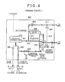
- FIG. 8 is a diagram showing a flow of oil inside a hydraulic circuit during engine travel
- FIG. 9 is a diagram summarizing a relationship between travel modes and states of a switch-over valve
- FIG. 10 is a flow chart (first) showing a processing procedure of an ECU.
- FIG. 11 is a flow chart (second) showing a processing procedure of an ECU.
- FIG. 1 is an overall block diagram of a vehicle 1 according to the present embodiment.
- the vehicle 1 travels by rotating a drive wheel 82 .
- the vehicle 1 includes an engine (E/G) 100 , a brake (Bcr) 110 , a first motor generator (hereinafter, referred to as a “first MG”) 200 , a power splitting apparatus 300 , a second motor generator (hereinafter, referred to as a “second MG”) 400 , an automatic transmission (A/T) 500 , a power control unit (hereinafter, referred to as a “PCU”) 600 , a battery 700 , and an electronic control unit (hereinafter, referred to as an “ECU”) 1000 .
- E/G engine
- Bcr brake
- first MG first motor generator
- second MG second motor generator
- A/T automatic transmission
- PCU power control unit
- battery 700 a battery 700
- ECU electronice control unit
- the engine 100 generates power for rotating the drive wheel 82 .
- the power generated by the engine 100 is inputted to the power splitting apparatus 300 .
- the power splitting apparatus 300 splits the power inputted from the engine 100 into power transmitted to the drive wheel 82 via the A/T 500 and power transmitted to the first MG 200 .
- the power splitting apparatus 300 is a planetary gear mechanism (a differential mechanism) including a sun gear (S) 310 , a ring gear (R) 320 , a carrier (C) 330 , and a pinion gear (P) 340 .
- the sun gear (S) 310 is coupled to a rotor of the first MG 200 .
- the ring gear (R) 320 is coupled to the drive wheel 82 via the A/T 500 .
- the pinion gear (P) 340 meshes with the sun gear (S) 310 and the ring gear (R) 320 .
- the carrier (C) 330 rotatably and revolvably holds the pinion gear (P) 340 .
- the carrier (C) 330 is coupled to a crankshaft 101 of the engine 100 .
- the brake 110 is an apparatus for fixing the crankshaft 101 .
- the brake 110 is controlled to be in an engaged state or a disengaged state in accordance with a control signal from the ECU 1000 .
- the engaged state of the brake 110 is a state in which the crankshaft 101 is fixed and is unable to rotate.
- the disengaged state of the brake 110 is a state in which the crankshaft 101 is rotatable.
- the brake 110 may be a friction material brake or a dog clutch brake.
- the first MG 200 and the second MG 400 are alternating current (AC) rotary electric machines and function as both motors and generators.
- the second MG 400 is provided between the power splitting apparatus 300 and the A/T 500 . More specifically, a rotor of the second MG 400 is connected to a rotary shaft 350 that couples the ring gear (R) 320 of the power splitting apparatus 300 and an input shaft of the A/T 500 to each other.
- the A/T 500 is provided between the rotary shaft 350 and a drive shaft 560 .
- the A/T 500 switches over a speed ratio (a ratio of an input shaft rotational speed with respect to an output shaft rotational speed) in accordance with a control signal from the ECU 1000 to any one of a plurality of speed stages (speed ratios) determined in advance.
- the PCU 600 converts direct current (DC) power supplied from the battery 700 into AC power and outputs the AC power to the first MG 200 and/or the second MG 400 . As a result, the first MG 200 and/or the second MG 400 are driven. In addition, the PCU 600 converts AC power generated by the first MG 200 and/or the second MG 400 into DC power and outputs the DC power to the battery 700 . As a result, the battery 700 is charged.
- DC direct current
- the battery 700 stores high-voltage (for example, around 200 V) DC power for driving the first MG 200 and/or the second MG 400 .
- the battery 700 is typically configured so as to include nickel hydride or lithium ions. Alternatively, a large-capacity capacitor can be adopted in place of the battery 700 .
- the vehicle 1 further includes an engine rotational speed sensor 10 , a vehicle speed sensor 15 , and resolvers 21 and 22 .
- the engine rotational speed sensor 10 detects a rotational speed of the engine 100 (hereinafter, referred to as an “engine rotational speed Ne”).
- the vehicle speed sensor 15 detects a rotational speed of the drive shaft 560 as a vehicle speed V.
- the resolver 21 detects a rotational speed of the first MG 200 (hereinafter, referred to as a “first MG rotational speed Ng”).
- the resolver 22 detects a rotational speed of the second MG 400 (hereinafter, referred to as a “second MG rotational speed Nm”). These sensors output detection results to the ECU 1000 .
- the vehicle 1 further includes an electric oil pump (hereinafter, also referred to as an “EOP”) 31 , a mechanical oil pump (hereinafter, also referred to as an “MOP”) 32 , and a hydraulic circuit 800 .
- EOP electric oil pump
- MOP mechanical oil pump
- the EOP 31 is driven by electric power (more specifically, power of a motor (not shown)) to pump oil stored in an oil pan and supplies the pumped oil to the hydraulic circuit 800 . Therefore, the EOP 31 can be driven even when the engine 100 is stopped.
- the EOP 31 is controlled according to a control signal from the ECU 1000 .
- the MOP 32 is driven by power of the engine 100 to pump oil stored in the oil pan and supplies the pumped oil to the hydraulic circuit 800 . Therefore, the MOP 32 is driven when the engine 100 is in operation and is stopped when the engine 100 is stopped.
- the hydraulic circuit 800 supplies oil from at least one of the EOP 31 and the MOP 32 to the first MG 200 and the second MG 400 .
- the oil supplied to the first MG 200 and the second MG 400 acts as a lubricating oil and a cooling oil of the first MG 200 and the second MG 400 .
- a dashed-dotted line shown in FIG. 1 represents a flow of oil from the hydraulic circuit 800 to the first MG 200 and the second MG 400 .
- the hydraulic circuit 800 also supplies oil to the brake 110 , the power splitting apparatus 300 , and the A/T 500 . A detailed configuration of the hydraulic circuit 800 will be described later.
- the ECU 1000 has a built-in central processing unit (CPU) and a built-in memory (both not shown) and executes prescribed arithmetic processing based on information stored in the memory or information from the respective sensors.
- the ECU 1000 controls respective devices mounted on the vehicle 1 based on results of the arithmetic processing.
- the vehicle 1 is capable of traveling in any mode of engine travel and motor travel. During engine travel, the vehicle 1 travels using power from the engine 100 in addition to the power from the first MG 200 and the second MG 400 . During engine travel, the brake 110 is placed in a disengaged state.
- the vehicle 1 travels using power of at least one of the first MG 200 and the second MG 400 without using power of the engine 100 .
- the crankshaft 101 is nonrotatably fixed by the brake 110 .
- motor travel can be switched over to travel using the power of both the first MG 200 and the second MG 400 (hereinafter, also referred to as “dual motor travel”) and to travel using the power of the second MG 400 without using the power of the first MG 200 (hereinafter, also referred to as “single motor travel”).
- FIGS. 2 to 4 respectively show alignment charts of the power splitting apparatus 300 during engine travel, dual motor travel, and single motor travel. Due to the power splitting apparatus 300 being configured as described above, as shown in FIGS. 2 to 4 , a rotational speed of the sun gear (S) 310 (in other words, the first MG rotational speed Ng), a rotational speed of the carrier (C) 330 (in other words, the engine rotational speed Ne), and a rotational speed of the ring gear (R) 320 (in other words, the second MG rotational speed Nm) form a relationship in which the rotational speeds are connected by straight lines on an alignment chart of the power splitting apparatus 300 (a relationship in which once any two rotational speeds are determined, the remaining rotational speed is determined).
- S sun gear
- C rotational speed of the carrier
- Ne the engine rotational speed Ne
- R ring gear
- the A/T 500 is provided between the ring gear (R) 320 and the drive shaft 560 . Therefore, a ratio of the second MG rotational speed Nm and the vehicle speed V is determined by a speed stage (a speed ratio) formed by the A/T 500 .
- FIGS. 2 to 4 exemplify cases where any forward speed stage of first to fourth speeds can be formed by the A/T 500 .
- the brake 110 is disengaged and the drive shaft 560 is rotated using a first MG torque Tg, a second MG torque Tm, and an engine torque Te.
- the crankshaft 101 is fixed by the brake 110 and the drive shaft 560 is rotated using both the first MG torque Tg and the second MG torque Tm.
- the crankshaft 101 is fixed by the brake 110 and the drive shaft 560 is rotated using the second MG torque Tm. In doing so, as shown in FIG. 4 , the first MG 200 is rotated with the rotation of the second MG 400 .
- the vehicle 1 is capable of switching between dual motor travel and single motor travel during motor travel. Uniformly supplying a cooling oil to both motors without taking these modes into consideration may possibly cause an unnecessary increase in so-called drag loss. In other words, when a same amount of the cooling oil as supplied during dual motor travel is supplied to the first MG 200 during single motor travel that does not use the first MG 200 , an unnecessary increase in drag loss occurs at the first MG 200 .
- the hydraulic circuit 800 includes a circuit for cutting off the supply of oil to the first MG 200 during single motor travel. Accordingly, drag loss that occurs at the first MG 200 during single motor travel is reduced.
- FIG. 5 is a diagram showing a detailed configuration of the hydraulic circuit 800 .
- the hydraulic circuit 800 is configured to include a hydraulic control unit 810 , a solenoid valve 820 , a pressure regulating valve 830 , and a switch-over valve 840 .
- Oil discharged by the EOP 31 and the MOP 32 is supplied to the hydraulic control unit 810 .
- a check valve 801 is provided between the EOP 31 and the hydraulic control unit 810 and a check valve 802 is provided between the MOP 32 and the hydraulic control unit 810 . Providing the check valves 801 and 802 prevents a backflow of oil into one of the oil pumps when oil is being discharged from the other oil pump.
- the hydraulic control unit 810 outputs oil from at least one of the EOP 31 and the MOP 32 to an oil passage 811 .
- the oil passage 811 branches at a branching section 812 into a first oil passage 813 for supplying oil to the first MG 200 and a second oil passage 814 for supplying oil to the second MG 400 .
- the second oil passage 814 is communicated with the second MG 400 .
- the switch-over valve 840 is provided on the first oil passage 813 .
- the first oil passage 813 is configured to include a first oil passage 813 A between the branching section 812 and the switch-over valve 840 and a first oil passage 813 B between the switch-over valve 840 and the first MG 200 .
- the first oil passage 813 A is communicated with any one of a recirculation passage 815 and the first oil passage 813 B via the switch-over valve 840 .
- the recirculation passage 815 merges with the second oil passage 814 at a confluence section 817 .
- Orifices 803 to 805 for regulating an oil flow rate are respectively provided at the first oil passage 813 B, the second oil passage 814 , and the recirculation passage 815 .
- the solenoid valve 820 is a switch-over control valve for switching between states of the switch-over valve 840 .
- the solenoid valve 820 When the solenoid valve 820 is placed in an energized state according to an ON command from the ECU 1000 , the solenoid valve 820 outputs pilot hydraulic pressure to the switch-over valve 840 .
- the solenoid valve 820 when the solenoid valve 820 is placed in a non-energized state according to an OFF command from the ECU 1000 , the solenoid valve 820 does not output pilot hydraulic pressure to the switch-over valve 840 .
- the pressure regulating valve 830 regulates hydraulic pressure from the MOP 32 and outputs the regulated hydraulic pressure to the switch-over valve 840 as backup hydraulic pressure.
- the switch-over valve 840 is configured to include a spool capable of moving inside a cylinder in a vertical direction and a spring that connects a lower surface of the spool with a lower surface of the cylinder. Pilot hydraulic pressure from the switch-over valve 840 is inputted into a cylinder on an upper side of the spool. Pilot hydraulic pressure from the pressure regulating valve 830 is inputted into a cylinder on a lower side of the spool.
- the state of the switch-over valve 840 is switched over to any of a state in which the first oil passage 813 A and the first oil passage 813 B are communicated with each other (hereinafter, referred to as an “OFF state”) and a state in which the first oil passage 813 A and the recirculation passage 815 are communicated with each other (hereinafter, referred to as an “ON state”).
- the state of the switch-over valve 840 is switched in accordance with the pilot hydraulic pressure. Specifically, when the pilot hydraulic pressure is not inputted, the spool is maintained at an initial position by the spring and a state is created in which the first oil passage 813 A and the first oil passage 813 B are communicated with each other. This state is the OFF state described above. Moreover, FIG. 5 shows a case where the switch-over valve 840 is in the OFF state.
- the pilot hydraulic pressure, the backup hydraulic pressure, and the elastic force of the spring are regulated so that a force with which the pilot hydraulic pressure pushes the spool downward is greater than a force with which the spring pushes the spool upward and that a force with which the backup hydraulic pressure and the spring push the spool upward is greater than a force with which the pilot hydraulic pressure pushes the spool downward.
- the ECU 1000 places the switch-over valve 840 in the OFF state by outputting an OFF command to the solenoid valve 820 .
- the ECU 1000 places the switch-over valve 840 in the ON state by outputting an ON command to the solenoid valve 820 .
- FIG. 6 is a diagram showing a flow of oil inside the hydraulic circuit 800 during dual motor travel.
- the MOP 32 is stopped and oil from the EOP 31 is supplied to the second MG 400 via the second oil passage 814 .
- the switch-over valve 840 since the pilot hydraulic pressure from the solenoid valve 820 is not inputted to the switch-over valve 840 , the switch-over valve 840 enters the OFF state. Accordingly, the first oil passage 813 A and the first oil passage 813 B are communicated with each other and the oil from the EOP 31 is also supplied to the first MG 200 .
- oil is supplied to both the first MG 200 and the second MG 400 .
- lubrication and cooling of the first MG 200 and the second MG 400 can be performed in a favorable manner.
- FIG. 7 is a diagram showing a flow of oil inside the hydraulic circuit 800 during single motor travel.
- oil from the EOP 31 is supplied to the second MG 400 via the second oil passage 814 in a similar manner to during dual motor travel (refer to FIG. 6 described above).
- the switch-over valve 840 enters the ON state due to the pilot hydraulic pressure from the solenoid valve 820 . Accordingly, the first oil passage 813 A and the first oil passage 813 B are cut off from each other and the oil from the EOP 31 is not supplied to the first MG 200 . Therefore, drag loss occurring at the first MG 200 that does not generate a drive force for vehicle travel is reduced.
- first oil passage 813 A and the recirculation passage 815 are communicated with each other and the oil from the first oil passage 813 A is supplied to the second MG 400 .
- oil is supplied to the second MG 400 by two paths, namely, a path that passes through the second oil passage 814 (the orifice 803 ) and a path that passes through the recirculation passage 815 (the orifice 804 ). Therefore, compared to a case where oil is supplied to the second MG 400 solely by the path that passes through the second oil passage 814 , fluid loss when supplying oil to the second MG 400 can be reduced.
- the switch-over valve 840 is placed in the OFF state by the backup hydraulic pressure regardless of the presence or absence of the pilot hydraulic pressure. In other words, the pilot hydraulic pressure is not required. Therefore, during engine travel, the ECU 1000 outputs the OFF command to the solenoid valve 820 . Accordingly, unnecessary energization at the solenoid valve 820 is suppressed.
- FIG. 8 is a diagram showing a flow of oil inside the hydraulic circuit 800 during engine travel.
- the MOP 32 is in operation and oil from the MOP 32 is supplied to the second MG 400 via the second oil passage 814 .
- the backup hydraulic pressure from the pressure regulating valve 830 is supplied to the switch-over valve 840 . Therefore, the switch-over valve 840 enters the OFF state regardless of the presence or absence of the pilot hydraulic pressure. Accordingly, the first oil passage 813 A and the first oil passage 813 B are communicated with each other and the oil from the MOP 32 is also supplied to the first MG 200 . As shown, according to the present embodiment, hydraulic pressure from the pressure regulating valve 830 (hydraulic pressure from the MOP 32 ) is used as backup hydraulic pressure for switching over states of the switch-over valve 840 .
- FIG. 9 is a diagram summarizing a relationship between travel modes and states of the switch-over valve 840 .
- the switch-over valve 840 enters the OFF state.
- the first MG 200 and the second MG 400 are set as oil supply destinations.
- the switch-over valve 840 enters the ON state.
- the second MG 400 is set as the oil supply destination.
- the switch-over valve 840 enters the OFF state regardless of the presence or absence of the pilot hydraulic pressure.
- the first MG 200 and the second MG 400 are set as oil supply destinations.
- the ECU 1000 outputs an OFF command to the solenoid valve 820 .
- the switch-over valve 840 is maintained in the OFF state during engine travel. Therefore, an ON command can be outputted during engine travel.
- FIG. 10 is a flow chart showing a processing procedure when a command is outputted by the ECU 1000 to the solenoid valve 820 .
- the ECU 1000 determines whether or not motor travel is in progress.
- motor travel is in progress (YES in S 10 )
- S 11 the ECU 1000 determines whether or not single motor travel is in progress.
- the ECU 1000 transfers processing to S 13 and outputs an OFF command to the solenoid valve 820 .
- the vehicle 1 includes the hydraulic circuit 800 for cutting off the supply of oil to the first MG 200 during single motor travel. Accordingly, drag loss that occurs at the first MG 200 during single motor travel can be reduced.
- oil supply cutoff is not necessarily restrictive.
- an oil supply amount to the first MG 200 during single motor travel can be reduced to below an oil supply amount to the first MG 200 during dual motor travel.
- the first MG 200 While supply of oil to the first MG 200 is cut off during single motor travel in the embodiment described above, the first MG 200 is rotated with the rotation of the second MG 400 even during single motor travel as described earlier with reference to FIG. 4 . Therefore, even during single motor travel, the first MG 200 requires a certain amount of lubricating oil.
- oil is temporarily supplied also to the first MG 200 when single motor travel is continued for a long period of time.
- FIG. 11 is a flow chart showing a processing procedure when a command is outputted by the ECU 1000 to the solenoid valve 820 according to the present embodiment. Moreover, among steps shown in FIG. 11 , steps denoted by the same numerals as those shown in FIG. 10 described earlier have already been described. Therefore, a description of these steps will not be repeated.
- the ECU 1000 determines whether or not a prescribed condition has been satisfied.
- the prescribed condition includes at least any of a condition that a duration of the single motor travel has exceeded a prescribed period of time and a condition that a travel distance by the single motor travel has exceeded a prescribed distance.
- the ECU 1000 When the prescribed condition is satisfied (YES in S 20 ), in S 21 , the ECU 1000 temporarily outputs an OFF command to the solenoid valve 820 . Accordingly, oil is temporarily supplied also to the first MG 200 . Accordingly, even when single motor travel is being continued for a long period of time, oil (lubricating oil) can be temporarily supplied to the first MG 200 .
Landscapes
- Engineering & Computer Science (AREA)
- Mechanical Engineering (AREA)
- General Engineering & Computer Science (AREA)
- Transportation (AREA)
- Power Engineering (AREA)
- Chemical & Material Sciences (AREA)
- Combustion & Propulsion (AREA)
- Sustainable Energy (AREA)
- Sustainable Development (AREA)
- Life Sciences & Earth Sciences (AREA)
- Hybrid Electric Vehicles (AREA)
- Electric Propulsion And Braking For Vehicles (AREA)
- Control Of Vehicle Engines Or Engines For Specific Uses (AREA)
Abstract
Description
Claims (4)
Applications Claiming Priority (2)
| Application Number | Priority Date | Filing Date | Title |
|---|---|---|---|
| JP2012-280922 | 2012-12-25 | ||
| JP2012280922A JP5803894B2 (en) | 2012-12-25 | 2012-12-25 | vehicle |
Publications (2)
| Publication Number | Publication Date |
|---|---|
| US20140179477A1 US20140179477A1 (en) | 2014-06-26 |
| US9005064B2 true US9005064B2 (en) | 2015-04-14 |
Family
ID=50975264
Family Applications (1)
| Application Number | Title | Priority Date | Filing Date |
|---|---|---|---|
| US14/140,129 Active US9005064B2 (en) | 2012-12-25 | 2013-12-24 | Vehicle |
Country Status (3)
| Country | Link |
|---|---|
| US (1) | US9005064B2 (en) |
| JP (1) | JP5803894B2 (en) |
| CN (1) | CN103899406A (en) |
Cited By (2)
| Publication number | Priority date | Publication date | Assignee | Title |
|---|---|---|---|---|
| US20140024493A1 (en) * | 2012-07-17 | 2014-01-23 | GM Global Technology Operations LLC | Hybrid powertrain with input brake |
| EP3543562A1 (en) * | 2018-03-19 | 2019-09-25 | Toyota Jidosha Kabushiki Kaisha | Lubrication device |
Families Citing this family (13)
| Publication number | Priority date | Publication date | Assignee | Title |
|---|---|---|---|---|
| JP6060955B2 (en) * | 2014-10-14 | 2017-01-18 | トヨタ自動車株式会社 | Hybrid vehicle drive control device |
| CN104442340B (en) * | 2014-12-02 | 2017-02-22 | 吉林大学 | Composite double-planet-row type hydraulically-driven hybrid power system |
| JP6187445B2 (en) * | 2014-12-18 | 2017-08-30 | トヨタ自動車株式会社 | Control device for hybrid vehicle |
| US9863528B2 (en) * | 2015-12-10 | 2018-01-09 | Hyundai Motor Company | Hydraulic pressure supply system of automatic transmission |
| JP6345194B2 (en) * | 2016-01-25 | 2018-06-20 | 本田技研工業株式会社 | Hybrid vehicle |
| KR101827102B1 (en) | 2016-04-28 | 2018-02-07 | 현대자동차주식회사 | Oil supply system of vehicl and controlling method thereof |
| GB2553808A (en) * | 2016-09-15 | 2018-03-21 | Arrival Ltd | Cooling electric motors in a vehicle drivetrain apparatus |
| JP6658558B2 (en) * | 2017-01-12 | 2020-03-04 | トヨタ自動車株式会社 | Cooling system for electric vehicles |
| US11421776B2 (en) * | 2017-12-21 | 2022-08-23 | Volvo Truck Corporation | Auxiliary transmission brake arrangement |
| CN110529584B (en) * | 2018-05-23 | 2021-02-05 | 广州汽车集团股份有限公司 | Power system cooling device |
| CN109027207A (en) * | 2018-09-19 | 2018-12-18 | 重庆青山工业有限责任公司 | A kind of automatic transmission hydraulic oil supply system |
| DE102022109970A1 (en) * | 2022-04-26 | 2023-10-26 | Audi Aktiengesellschaft | Geared motor for a motor vehicle and motor vehicle with a geared motor |
| CN115949636A (en) * | 2022-12-02 | 2023-04-11 | 奇瑞汽车股份有限公司 | Automobile hydraulic system and hybrid electric vehicle |
Citations (6)
| Publication number | Priority date | Publication date | Assignee | Title |
|---|---|---|---|---|
| US20070049442A1 (en) * | 2005-09-01 | 2007-03-01 | Long Charles F | Multiplexed trim valve system for an electrically variable hybrid transmission |
| US20070293362A1 (en) * | 2006-06-15 | 2007-12-20 | Toyota Jidosha Kabushiki Kaisha | Control device for vehicle drive apparatus |
| US20080103003A1 (en) | 2006-10-26 | 2008-05-01 | Sah Jy-Jen F | Method and apparatus to control operation of a hydraulic control circuit for an electro-mechanical transmission |
| JP2008265598A (en) | 2007-04-23 | 2008-11-06 | Toyota Motor Corp | Vehicle and control method thereof |
| JP2010083361A (en) | 2008-09-30 | 2010-04-15 | Toyota Motor Corp | Controller of power transmission for vehicle |
| US20110070991A1 (en) * | 2007-09-26 | 2011-03-24 | Gm Global Technology Operations, Inc. | Electro-mechanical transmission control system |
Family Cites Families (5)
| Publication number | Priority date | Publication date | Assignee | Title |
|---|---|---|---|---|
| JPH08326780A (en) * | 1995-06-05 | 1996-12-10 | Jatco Corp | Lubricating device of multiple disc clutch |
| JP4356646B2 (en) * | 2005-05-06 | 2009-11-04 | トヨタ自動車株式会社 | Vehicle control device |
| US8448460B2 (en) * | 2008-06-23 | 2013-05-28 | GM Global Technology Operations LLC | Vehicular combination chiller bypass system and method |
| JP5321037B2 (en) * | 2008-12-19 | 2013-10-23 | マツダ株式会社 | Hydraulic control device for vehicle drive device |
| US8387572B2 (en) * | 2009-12-04 | 2013-03-05 | Ford Global Technologies, Llc | Auxiliary pump scheme for a cooling system in a hybrid-electric vehicle |
-
2012
- 2012-12-25 JP JP2012280922A patent/JP5803894B2/en not_active Expired - Fee Related
-
2013
- 2013-12-23 CN CN201310717626.XA patent/CN103899406A/en active Pending
- 2013-12-24 US US14/140,129 patent/US9005064B2/en active Active
Patent Citations (6)
| Publication number | Priority date | Publication date | Assignee | Title |
|---|---|---|---|---|
| US20070049442A1 (en) * | 2005-09-01 | 2007-03-01 | Long Charles F | Multiplexed trim valve system for an electrically variable hybrid transmission |
| US20070293362A1 (en) * | 2006-06-15 | 2007-12-20 | Toyota Jidosha Kabushiki Kaisha | Control device for vehicle drive apparatus |
| US20080103003A1 (en) | 2006-10-26 | 2008-05-01 | Sah Jy-Jen F | Method and apparatus to control operation of a hydraulic control circuit for an electro-mechanical transmission |
| JP2008265598A (en) | 2007-04-23 | 2008-11-06 | Toyota Motor Corp | Vehicle and control method thereof |
| US20110070991A1 (en) * | 2007-09-26 | 2011-03-24 | Gm Global Technology Operations, Inc. | Electro-mechanical transmission control system |
| JP2010083361A (en) | 2008-09-30 | 2010-04-15 | Toyota Motor Corp | Controller of power transmission for vehicle |
Cited By (3)
| Publication number | Priority date | Publication date | Assignee | Title |
|---|---|---|---|---|
| US20140024493A1 (en) * | 2012-07-17 | 2014-01-23 | GM Global Technology Operations LLC | Hybrid powertrain with input brake |
| US9174522B2 (en) * | 2012-07-17 | 2015-11-03 | GM Global Technology Operations LLC | Hybrid powertrain with input brake |
| EP3543562A1 (en) * | 2018-03-19 | 2019-09-25 | Toyota Jidosha Kabushiki Kaisha | Lubrication device |
Also Published As
| Publication number | Publication date |
|---|---|
| JP5803894B2 (en) | 2015-11-04 |
| US20140179477A1 (en) | 2014-06-26 |
| JP2014124977A (en) | 2014-07-07 |
| CN103899406A (en) | 2014-07-02 |
Similar Documents
| Publication | Publication Date | Title |
|---|---|---|
| US9005064B2 (en) | Vehicle | |
| EP3067588B1 (en) | Lubricating structure for hybrid vehicle | |
| US10030755B2 (en) | Torque vectoring device | |
| US9981665B2 (en) | Energy storage and delivery for power trains of work vehicles | |
| JP5578127B2 (en) | Hybrid drive unit | |
| JP4722710B2 (en) | Hydraulic control device for transmission | |
| US10214093B2 (en) | Hybrid vehicle operable in series mode and in series-parallel mode | |
| US9657612B2 (en) | Control system for electric vehicle | |
| WO2014157689A1 (en) | Oil supply device | |
| US9975545B2 (en) | Hybrid vehicle | |
| JP2010126047A (en) | Driving device for hybrid car | |
| US10173515B2 (en) | Hybrid vehicle | |
| US9688132B2 (en) | Hybrid vehicle | |
| AU2009206423A1 (en) | Electro-hydraulic machine for hybri drive system | |
| US20160023653A1 (en) | Control apparatus for vehicle | |
| JP5321037B2 (en) | Hydraulic control device for vehicle drive device | |
| US9777830B2 (en) | Power transmission device | |
| JP5115465B2 (en) | Drive device | |
| JP5728181B2 (en) | Hydraulic clutch | |
| US11192551B2 (en) | Vehicle control device | |
| US11739834B2 (en) | Oil supply device and vehicle drive transmission device | |
| JP5182066B2 (en) | Fluid pressure circuit structure of transmission | |
| JP2010069980A (en) | Starting device for vehicle | |
| JP2014240263A (en) | Oil pump system of hybrid vehicle and control method of the same | |
| JP2014502934A (en) | Dual drive mechanism for driving automobile hydraulic pump and control method thereof |
Legal Events
| Date | Code | Title | Description |
|---|---|---|---|
| AS | Assignment |
Owner name: TOYOTA JIDOSHA KABUSHIKI KAISHA, JAPAN Free format text: ASSIGNMENT OF ASSIGNORS INTEREST;ASSIGNORS:YAMAMOTO, MASAFUMI;TABATA, ATSUSHI;OKUDA, KOICHI;AND OTHERS;SIGNING DATES FROM 20131101 TO 20131107;REEL/FRAME:031845/0591 |
|
| STCF | Information on status: patent grant |
Free format text: PATENTED CASE |
|
| FEPP | Fee payment procedure |
Free format text: PAYOR NUMBER ASSIGNED (ORIGINAL EVENT CODE: ASPN); ENTITY STATUS OF PATENT OWNER: LARGE ENTITY |
|
| MAFP | Maintenance fee payment |
Free format text: PAYMENT OF MAINTENANCE FEE, 4TH YEAR, LARGE ENTITY (ORIGINAL EVENT CODE: M1551); ENTITY STATUS OF PATENT OWNER: LARGE ENTITY Year of fee payment: 4 |
|
| MAFP | Maintenance fee payment |
Free format text: PAYMENT OF MAINTENANCE FEE, 8TH YEAR, LARGE ENTITY (ORIGINAL EVENT CODE: M1552); ENTITY STATUS OF PATENT OWNER: LARGE ENTITY Year of fee payment: 8 |