US9004849B2 - Gas turbine engine forward bearing compartment architecture - Google Patents
Gas turbine engine forward bearing compartment architecture Download PDFInfo
- Publication number
- US9004849B2 US9004849B2 US13/346,832 US201213346832A US9004849B2 US 9004849 B2 US9004849 B2 US 9004849B2 US 201213346832 A US201213346832 A US 201213346832A US 9004849 B2 US9004849 B2 US 9004849B2
- Authority
- US
- United States
- Prior art keywords
- turbine engine
- gas turbine
- recited
- bearing
- front center
- Prior art date
- Legal status (The legal status is an assumption and is not a legal conclusion. Google has not performed a legal analysis and makes no representation as to the accuracy of the status listed.)
- Active, expires
Links
Images


Classifications
-
- F—MECHANICAL ENGINEERING; LIGHTING; HEATING; WEAPONS; BLASTING
- F02—COMBUSTION ENGINES; HOT-GAS OR COMBUSTION-PRODUCT ENGINE PLANTS
- F02C—GAS-TURBINE PLANTS; AIR INTAKES FOR JET-PROPULSION PLANTS; CONTROLLING FUEL SUPPLY IN AIR-BREATHING JET-PROPULSION PLANTS
- F02C7/00—Features, components parts, details or accessories, not provided for in, or of interest apart form groups F02C1/00 - F02C6/00; Air intakes for jet-propulsion plants
- F02C7/06—Arrangements of bearings; Lubricating
-
- F—MECHANICAL ENGINEERING; LIGHTING; HEATING; WEAPONS; BLASTING
- F01—MACHINES OR ENGINES IN GENERAL; ENGINE PLANTS IN GENERAL; STEAM ENGINES
- F01D—NON-POSITIVE DISPLACEMENT MACHINES OR ENGINES, e.g. STEAM TURBINES
- F01D25/00—Component parts, details, or accessories, not provided for in, or of interest apart from, other groups
- F01D25/16—Arrangement of bearings; Supporting or mounting bearings in casings
-
- F—MECHANICAL ENGINEERING; LIGHTING; HEATING; WEAPONS; BLASTING
- F02—COMBUSTION ENGINES; HOT-GAS OR COMBUSTION-PRODUCT ENGINE PLANTS
- F02C—GAS-TURBINE PLANTS; AIR INTAKES FOR JET-PROPULSION PLANTS; CONTROLLING FUEL SUPPLY IN AIR-BREATHING JET-PROPULSION PLANTS
- F02C7/00—Features, components parts, details or accessories, not provided for in, or of interest apart form groups F02C1/00 - F02C6/00; Air intakes for jet-propulsion plants
- F02C7/12—Cooling of plants
-
- F—MECHANICAL ENGINEERING; LIGHTING; HEATING; WEAPONS; BLASTING
- F02—COMBUSTION ENGINES; HOT-GAS OR COMBUSTION-PRODUCT ENGINE PLANTS
- F02C—GAS-TURBINE PLANTS; AIR INTAKES FOR JET-PROPULSION PLANTS; CONTROLLING FUEL SUPPLY IN AIR-BREATHING JET-PROPULSION PLANTS
- F02C7/00—Features, components parts, details or accessories, not provided for in, or of interest apart form groups F02C1/00 - F02C6/00; Air intakes for jet-propulsion plants
- F02C7/28—Arrangement of seals
-
- F—MECHANICAL ENGINEERING; LIGHTING; HEATING; WEAPONS; BLASTING
- F02—COMBUSTION ENGINES; HOT-GAS OR COMBUSTION-PRODUCT ENGINE PLANTS
- F02C—GAS-TURBINE PLANTS; AIR INTAKES FOR JET-PROPULSION PLANTS; CONTROLLING FUEL SUPPLY IN AIR-BREATHING JET-PROPULSION PLANTS
- F02C7/00—Features, components parts, details or accessories, not provided for in, or of interest apart form groups F02C1/00 - F02C6/00; Air intakes for jet-propulsion plants
- F02C7/36—Power transmission arrangements between the different shafts of the gas turbine plant, or between the gas-turbine plant and the power user
-
- F—MECHANICAL ENGINEERING; LIGHTING; HEATING; WEAPONS; BLASTING
- F02—COMBUSTION ENGINES; HOT-GAS OR COMBUSTION-PRODUCT ENGINE PLANTS
- F02K—JET-PROPULSION PLANTS
- F02K3/00—Plants including a gas turbine driving a compressor or a ducted fan
- F02K3/02—Plants including a gas turbine driving a compressor or a ducted fan in which part of the working fluid by-passes the turbine and combustion chamber
- F02K3/04—Plants including a gas turbine driving a compressor or a ducted fan in which part of the working fluid by-passes the turbine and combustion chamber the plant including ducted fans, i.e. fans with high volume, low pressure outputs, for augmenting the jet thrust, e.g. of double-flow type
- F02K3/06—Plants including a gas turbine driving a compressor or a ducted fan in which part of the working fluid by-passes the turbine and combustion chamber the plant including ducted fans, i.e. fans with high volume, low pressure outputs, for augmenting the jet thrust, e.g. of double-flow type with front fan
Definitions
- the present disclosure relates to a gas turbine engine, and in particular, to a case structure therefor.
- Geared turbofan architectures may utilize epicyclic reduction gearboxes with planetary or star gear trains for their compact design and efficient high gear reduction capabilities.
- the geared turbofan architecture de-couples a fan rotor from a low spool through the reduction gearbox which results in isolation of the forwardmost bearing compartment.
- a gas turbine engine includes a geared architecture at least partially supported by a front center body case structure.
- a bearing structure mounted to the front center body case structure to rotationally support a shaft driven by the geared architecture.
- a bearing compartment passage structure in communication with the bearing structure through the front center body case structure.
- a method of communicating a buffer supply air for a gas turbine engine includes communicating a buffer supply air across an annular core flow path.
- FIG. 1 is a schematic cross-section of a gas turbine engine
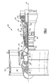
- FIG. 2 is an enlarged schematic cross-section of a sectional of the gas turbine engine
- FIG. 3 is a schematic view of a gas turbine engine with a bearing compartment passage structure which bypasses around a geared architecture
- FIG. 4 is an enlarged schematic cross-section of a sectional of the gas turbine engine, which illustrates the bearing compartment passage structure.
- FIG. 1 schematically illustrates a gas turbine engine 20 .
- the gas turbine engine 20 is disclosed herein as a two-spool turbofan that generally incorporates a fan section 22 , a compressor section 24 , a combustor section 26 and a turbine section 28 .
- Alternative engines might include an augmentor section (not shown) among other systems or features.
- the fan section 22 drives air along a bypass flowpath while the compressor section 24 drives air along a core flowpath for compression and communication into the combustor section 26 then expansion through the turbine section 28 .
- turbofan gas turbine engine in the disclosed non-limiting embodiment, it should be understood that the concepts described herein are not limited to use with turbofans as the teachings may be applied to other types of turbine engines such as a three-spool (plus fan) engine wherein an intermediate spool includes an intermediate pressure compressor (IPC) between the LPC and HPC and an intermediate pressure turbine (IPT) between the HPT and LPT.
- IPC intermediate pressure compressor
- IPT intermediate pressure turbine
- the engine 20 generally includes a low spool 30 and a high spool 32 mounted for rotation about an engine central longitudinal axis A relative to an engine static structure 36 via several bearing structures 38 .
- the low spool 30 generally includes an inner shaft 40 that interconnects a fan 42 , a low pressure compressor 44 (“LPC”) and a low pressure turbine 46 (“LPT”).
- the inner shaft 40 drives the fan 42 through a geared architecture 48 to drive the fan 42 at a lower speed than the low spool 30 .
- An exemplary reduction transmission is an epicyclic transmission, namely a planetary or star gear system.
- the high spool 32 includes an outer shaft 50 that interconnects a high pressure compressor 52 (“HPC”) and high pressure turbine 54 (“HPT”).
- a combustor 56 is arranged between the high pressure compressor 52 and the high pressure turbine 54 .
- the inner shaft 40 and the outer shaft 50 are concentric and rotate about the engine central longitudinal axis A which is collinear with their longitudinal axes.
- Core airflow is compressed by the low pressure compressor 44 then the high pressure compressor 52 , mixed with the fuel and burned in the combustor 56 , then expanded over the high pressure turbine 54 and low pressure turbine 46 .
- the turbines 54 , 46 rotationally drive the respective low spool 30 and high spool 32 in response to the expansion.
- bearing structures 38 includes a # 1 bearing structure 38 - 1 forward of the gearbox 72 and a # 2 bearing structure 38 - 2 located aft of the gearbox 72 .
- the engine static structure 36 proximate the compressor section 24 generally includes a front center body case structure 60 and an intermediate case structure 62 which mounts aft of the front center body case structure 60 . It should be appreciated that various case structures may alternatively or additionally be provided, yet benefit from the architecture described herein.
- the front center body case structure 60 generally defines an annular core flow path 64 A for the core airflow into the low pressure compressor 44 .
- the intermediate case structure 62 defines the core flow path 64 B aft of the core flow path 64 A into the high pressure compressor 52 core flow path 64 C.
- the core flow path 64 B is generally radially inward of the core flow path 64 A to transition into the radially smaller diameter core flow path 64 C. That is, the core flow path 64 B generally defines a “wasp waist” gas turbine engine architecture.
- the # 2 bearing structure 38 - 2 at least partially supports the inner shaft 40 relative to the front center body case structure 60 .
- a # 3 bearing structure 38 - 3 generally supports the outer shaft 50 relative the intermediate case structure 62 . That is, the # 2 bearing structure 38 - 2 at least partially supports the low spool 30 and the # 3 bearing structure 38 - 3 at least partially supports the high spool 32 . It should be appreciated that various bearing systems such as thrust bearing structures and mount arrangements will benefit herefrom.
- a flex support 68 provides a flexible attachment of the geared architecture 48 within the front center body case structure 60 .
- the flex support 68 reacts the torsional loads from the geared architecture 48 and facilitates vibration absorption as well as other support functions.
- a centering spring 70 which is a generally cylindrical cage-like structural component with a multiple of beams that extend between flange end structures, resiliently positions the # 2 bearing structure 38 - 2 with respect to the low spool 30 .
- the beams are double-tapered beams arrayed circumferentially to control a radial spring rate that may be selected based on a plurality of considerations including, but not limited to, bearing loading, bearing life, rotor dynamics, and rotor deflection considerations.
- the gearbox 72 of the geared architecture 48 is driven by the low spool 30 in the disclosed non-limiting embodiment through a coupling shaft 74 .
- the coupling shaft 74 transfers torque through the # 2 bearing structure 38 - 2 to the gearbox 72 as well as facilitates the segregation of vibrations and other transients.
- the coupling shaft 74 in the disclosed non-limiting embodiment includes a forward coupling shaft section 76 and an aft coupling shaft section 78 .
- the forward coupling shaft section 76 includes an interface spline 80 which mates with the gearbox 72 .
- An interface spline 82 of the aft coupling shaft section 78 connects the coupling shaft 74 to the low spool 30 through, in this non limiting embodiment, a low pressure compressor hub 84 of the low pressure compressor 44 .
- a fan rotor bearing support structure 86 aft of the fan 42 extends radially inward from the front center body case structure 60 .
- the fan rotor bearing support structure 86 and the front center body case structure 60 defines a bearing compartment B- 2 .
- various bearing structures 38 and seals 88 may be supported by the fan rotor bearing support structure 86 to contain oil and support rotation of an output shaft 100 which connects with the geared architecture 48 to drive the fan 42 .
- the low pressure compressor hub 84 of the low pressure compressor 44 includes a tubular hub 90 and a frustro-conical web 92 .
- the tubular hub 90 mounts to the inner shaft 40 through, for example, a splined interface adjacent to the # 2 bearing structure 38 - 2 .
- the frustro-conical web 92 extends in a forwardly direction from the tubular hub 90 axially between the # 2 bearing structure 38 - 2 and the # 3 bearing structure 38 - 3 . That is, the frustro-conical web 92 is axially located between the bearing structures 38 - 2 , 38 - 3 .
- the # 1 bearing structure 38 - 1 supports the output shaft 100 which connects the geared architecture 48 to the fan 42 .
- the # 1 bearing structure 38 - 1 is located within a bearing compartment B- 1 that is isolated by the geared architecture 48 from bearing compartment B- 2 . That is, the # 1 bearing compartment B- 1 is isolated from the engine core aft of the geared architecture 48 and receives its buffer pressurization supply of buffer supply air through a # 1 bearing compartment passage structure 110 that crosses the annular core flow path 64 A for the core airflow into the low pressure compressor 44 ( FIG. 3 ).
- the # 1 bearing compartment passage structure 110 is in communication with the core engine such as with the high pressure compressor 52 to supply a higher pressure bleed air flow of buffer supply air into the # 1 bearing compartment B- 1 such as the seal 88 - 1 to, for example, pressurize the seal 88 - 1 and seal lubricating fluid with respect to the # 1 bearing structure 38 - 1 .
- the buffer supply air may be communicated from various other sources and may pass through, for example, a conditioning device 112 such as a buffer heat exchanger.
- the conditioning device 112 may further condition bleed flow C 1 , C 2 from the high pressure compressor It should be appreciated the various bleed sources from the high pressure compressor 52 may be selected through a valve 116 .
- the # 1 bearing compartment passage structure 110 may be at least partially defined by a hollow front center body strut 60 S of the front center body case structure 60 to permit the buffer supply air to cross the annular core flow path 64 A without flow interference. That is, the buffer supply air is communicated through the hollow front center body strut 60 S and the core airflow passes around the hollow front center body strut 60 S.
- the buffer supply air is communicated through a passage 114 in the fan rotor bearing support structure 86 to, for example, the seal 88 - 1 . It should be appreciated that various passages may alternatively or additionally be provided.
- the passage of buffer supply air through the fan rotor bearing support structure 86 advantageously promotes heat transfer between the buffer supply air and the # 1 bearing compartment B- 1 to reduce buffer supply air maximum temperate at high power condition and increases buffer supply air minimum temperatures at lower power settings.
- the # 1 bearing structure 38 - 1 operates at a generally constant temperature
- the # 1 bearing compartment B- 1 operates as a thermal ground with respect to the buffer supply air.
- the buffer supply air Downstream of the # 1 bearing compartment B- 1 , the buffer supply air may be communicated in various manners for various usages such as toward the spinner 120 to facilitate spinner die-icing.
- the buffer supply air may alternatively or additionally be ejected outward aft of the fan 42 to recirculate into the annular core flow path 64 A to minimize any effect upon engine efficiency.
Landscapes
- Engineering & Computer Science (AREA)
- Chemical & Material Sciences (AREA)
- Combustion & Propulsion (AREA)
- Mechanical Engineering (AREA)
- General Engineering & Computer Science (AREA)
- Structures Of Non-Positive Displacement Pumps (AREA)
- Rolling Contact Bearings (AREA)
Abstract
Description
Claims (20)
Priority Applications (12)
| Application Number | Priority Date | Filing Date | Title |
|---|---|---|---|
| US13/346,832 US9004849B2 (en) | 2012-01-10 | 2012-01-10 | Gas turbine engine forward bearing compartment architecture |
| EP12865495.1A EP2802747B8 (en) | 2012-01-10 | 2012-12-27 | Gas turbine engine forward bearing compartment architecture |
| PCT/US2012/071827 WO2013106201A1 (en) | 2012-01-10 | 2012-12-27 | Gas turbine engine forward bearing compartment architecture |
| US14/640,251 US9410483B2 (en) | 2012-01-10 | 2015-03-06 | Gas turbine engine forward bearing compartment architecture |
| US14/745,724 US9416677B2 (en) | 2012-01-10 | 2015-06-22 | Gas turbine engine forward bearing compartment architecture |
| US15/046,524 US9885249B2 (en) | 2012-01-10 | 2016-02-18 | Gas turbine engine forward bearing compartment architecture |
| US15/865,393 US10465549B2 (en) | 2012-01-10 | 2018-01-09 | Gas turbine engine forward bearing compartment architecture |
| US15/939,508 US10550714B2 (en) | 2012-01-10 | 2018-03-29 | Gas turbine engine forward bearing compartment architecture |
| US15/939,467 US10550713B2 (en) | 2012-01-10 | 2018-03-29 | Gas turbine engine forward bearing compartment architecture |
| US16/779,768 US10920603B2 (en) | 2012-01-10 | 2020-02-03 | Gas turbine engine forward bearing compartment architecture |
| US17/164,908 US11293299B2 (en) | 2012-01-10 | 2021-02-02 | Gas turbine engine forward bearing compartment architecture |
| US17/688,957 US11549387B2 (en) | 2012-01-10 | 2022-03-08 | Gas turbine engine forward bearing compartment architecture |
Applications Claiming Priority (1)
| Application Number | Priority Date | Filing Date | Title |
|---|---|---|---|
| US13/346,832 US9004849B2 (en) | 2012-01-10 | 2012-01-10 | Gas turbine engine forward bearing compartment architecture |
Related Child Applications (1)
| Application Number | Title | Priority Date | Filing Date |
|---|---|---|---|
| US14/640,251 Continuation US9410483B2 (en) | 2012-01-10 | 2015-03-06 | Gas turbine engine forward bearing compartment architecture |
Publications (2)
| Publication Number | Publication Date |
|---|---|
| US20130177385A1 US20130177385A1 (en) | 2013-07-11 |
| US9004849B2 true US9004849B2 (en) | 2015-04-14 |
Family
ID=48744044
Family Applications (2)
| Application Number | Title | Priority Date | Filing Date |
|---|---|---|---|
| US13/346,832 Active 2033-09-08 US9004849B2 (en) | 2012-01-10 | 2012-01-10 | Gas turbine engine forward bearing compartment architecture |
| US14/640,251 Active US9410483B2 (en) | 2012-01-10 | 2015-03-06 | Gas turbine engine forward bearing compartment architecture |
Family Applications After (1)
| Application Number | Title | Priority Date | Filing Date |
|---|---|---|---|
| US14/640,251 Active US9410483B2 (en) | 2012-01-10 | 2015-03-06 | Gas turbine engine forward bearing compartment architecture |
Country Status (3)
| Country | Link |
|---|---|
| US (2) | US9004849B2 (en) |
| EP (1) | EP2802747B8 (en) |
| WO (1) | WO2013106201A1 (en) |
Cited By (15)
| Publication number | Priority date | Publication date | Assignee | Title |
|---|---|---|---|---|
| US20150377027A1 (en) * | 2014-05-19 | 2015-12-31 | Rolls-Royce Plc | Fan disc |
| US9764848B1 (en) | 2016-03-07 | 2017-09-19 | General Electric Company | Propulsion system for an aircraft |
| US9869206B2 (en) | 2016-06-21 | 2018-01-16 | United Technologies Corporation | Securing a centering spring to a static structure with mounting tabs |
| US10000293B2 (en) | 2015-01-23 | 2018-06-19 | General Electric Company | Gas-electric propulsion system for an aircraft |
| US10071811B2 (en) | 2016-08-22 | 2018-09-11 | General Electric Company | Embedded electric machine |
| US10093428B2 (en) | 2016-08-22 | 2018-10-09 | General Electric Company | Electric propulsion system |
| US10308366B2 (en) | 2016-08-22 | 2019-06-04 | General Electric Company | Embedded electric machine |
| US10487839B2 (en) | 2016-08-22 | 2019-11-26 | General Electric Company | Embedded electric machine |
| US10762726B2 (en) | 2017-06-13 | 2020-09-01 | General Electric Company | Hybrid-electric propulsion system for an aircraft |
| US10793281B2 (en) | 2017-02-10 | 2020-10-06 | General Electric Company | Propulsion system for an aircraft |
| US10822103B2 (en) | 2017-02-10 | 2020-11-03 | General Electric Company | Propulsor assembly for an aircraft |
| US11097849B2 (en) | 2018-09-10 | 2021-08-24 | General Electric Company | Aircraft having an aft engine |
| US11149578B2 (en) | 2017-02-10 | 2021-10-19 | General Electric Company | Propulsion system for an aircraft |
| US11156128B2 (en) | 2018-08-22 | 2021-10-26 | General Electric Company | Embedded electric machine |
| US12149154B2 (en) | 2021-07-22 | 2024-11-19 | General Electric Company | Electric machine having a hybrid insulative-conductive manifold |
Families Citing this family (20)
| Publication number | Priority date | Publication date | Assignee | Title |
|---|---|---|---|---|
| US9416677B2 (en) | 2012-01-10 | 2016-08-16 | United Technologies Corporation | Gas turbine engine forward bearing compartment architecture |
| US11732892B2 (en) * | 2013-08-14 | 2023-08-22 | General Electric Company | Gas turbomachine diffuser assembly with radial flow splitters |
| FR3013385B1 (en) * | 2013-11-21 | 2015-11-13 | Snecma | PRE-SEALED SPEAKER DURING MODULAR DISASSEMBLY OF A REDUCING TURBOREACTOR |
| EP3109411A1 (en) * | 2015-06-22 | 2016-12-28 | United Technologies Corporation | Gas turbine engine forward bearing compartment architecture |
| FR3043714B1 (en) * | 2015-11-16 | 2017-12-22 | Snecma | FRONT AIRCRAFT TURBOMACHINE PART COMPRISING A SINGLE BLOWER CONDUCTED BY A REDUCER, AS WELL AS STRUCTURAL OUTPUT LEAD DIRECTORS FITTED PARTLY BEFORE A SEPARATION SPOUT |
| FR3049006B1 (en) * | 2016-03-15 | 2018-03-16 | Safran Aircraft Engines | TURBOREACTOR HAVING A SIMPLIFIED BEARING LUBRICATION GROUP |
| FR3049007B1 (en) * | 2016-03-15 | 2019-05-10 | Safran Aircraft Engines | TURBOREACTOR HAVING A SIMPLIFIED BEARING LUBRICATION GROUP |
| US20170291693A1 (en) * | 2016-04-11 | 2017-10-12 | General Electric Company | Electric propulsion engine for an aircraft |
| US10344614B2 (en) | 2016-04-12 | 2019-07-09 | United Technologies Corporation | Active clearance control for a turbine and case |
| US10267334B2 (en) * | 2016-08-01 | 2019-04-23 | United Technologies Corporation | Annular heatshield |
| FR3062678B1 (en) * | 2017-02-07 | 2019-04-19 | Safran Aircraft Engines | DOUBLE FLOW TURBOREACTOR COMPRISING AN INTERMEDIATE VEHICLE DEDICATED TO AIR SUPPLY BY RADIAL ARMS OF AN EXHAUST CASE OF THIS TURBOJET ENGINE |
| EP3587764A1 (en) * | 2018-06-27 | 2020-01-01 | Rolls-Royce Deutschland Ltd & Co KG | Gas turbine |
| EP3587768A1 (en) | 2018-06-27 | 2020-01-01 | Rolls-Royce Deutschland Ltd & Co KG | Gas turbine |
| FR3086341B1 (en) * | 2018-09-24 | 2020-11-27 | Safran Aircraft Engines | TURBOMACHINE WITH REDUCER FOR AN AIRCRAFT |
| DE102018132675A1 (en) * | 2018-12-18 | 2020-06-18 | Rolls-Royce Deutschland Ltd & Co Kg | Gas turbine engine |
| GB201906170D0 (en) | 2019-05-02 | 2019-06-19 | Rolls Royce Plc | Gas turbine engine with a double wall core casing |
| GB201906167D0 (en) * | 2019-05-02 | 2019-06-19 | Rolls Royce Plc | Gas turbine engine with core mount |
| GB201906164D0 (en) | 2019-05-02 | 2019-06-19 | Rolls Royce Plc | Gas turbine engine |
| CN114060118B (en) * | 2021-10-20 | 2022-09-23 | 中国航发四川燃气涡轮研究院 | Bleed air conversion device |
| CN115816071B (en) * | 2023-02-07 | 2023-04-28 | 成都中科翼能科技有限公司 | Assembling method of gas turbine supporting structure |
Citations (11)
| Publication number | Priority date | Publication date | Assignee | Title |
|---|---|---|---|---|
| US3382670A (en) | 1966-12-01 | 1968-05-14 | Gen Electric | Gas turbine engine lubrication system |
| US3844110A (en) | 1973-02-26 | 1974-10-29 | Gen Electric | Gas turbine engine internal lubricant sump venting and pressurization system |
| US3990814A (en) | 1975-06-25 | 1976-11-09 | United Technologies Corporation | Spinner |
| US4645415A (en) * | 1983-12-23 | 1987-02-24 | United Technologies Corporation | Air cooler for providing buffer air to a bearing compartment |
| US5080555A (en) * | 1990-11-16 | 1992-01-14 | General Motors Corporation | Turbine support for gas turbine engine |
| US6623238B2 (en) * | 1998-08-21 | 2003-09-23 | Honeywell International, Inc. | Air turbine starter with seal assembly |
| US7201558B2 (en) * | 2005-05-05 | 2007-04-10 | United Technologies Corporation | Seal arrangement for a fan-turbine rotor assembly |
| US20070084188A1 (en) | 2005-10-19 | 2007-04-19 | General Electric Company | Gas turbine engine assembly and methods of assembling same |
| US20070193276A1 (en) | 2006-02-21 | 2007-08-23 | General Electric Company | Supercore sump vent pressure control |
| US7383686B2 (en) * | 2004-12-13 | 2008-06-10 | Honeywell International Inc. | Secondary flow, high pressure turbine module cooling air system for recuperated gas turbine engines |
| US20100160105A1 (en) | 2006-07-05 | 2010-06-24 | Sheridan William G | Oil baffle for gas turbine fan drive gear system |
Family Cites Families (26)
| Publication number | Priority date | Publication date | Assignee | Title |
|---|---|---|---|---|
| US3287906A (en) | 1965-07-20 | 1966-11-29 | Gen Motors Corp | Cooled gas turbine vanes |
| GB1350431A (en) | 1971-01-08 | 1974-04-18 | Secr Defence | Gearing |
| US3892358A (en) | 1971-03-17 | 1975-07-01 | Gen Electric | Nozzle seal |
| US4130872A (en) | 1975-10-10 | 1978-12-19 | The United States Of America As Represented By The Secretary Of The Air Force | Method and system of controlling a jet engine for avoiding engine surge |
| GB1516041A (en) | 1977-02-14 | 1978-06-28 | Secr Defence | Multistage axial flow compressor stators |
| GB2041090A (en) | 1979-01-31 | 1980-09-03 | Rolls Royce | By-pass gas turbine engines |
| US5447411A (en) | 1993-06-10 | 1995-09-05 | Martin Marietta Corporation | Light weight fan blade containment system |
| US5524847A (en) | 1993-09-07 | 1996-06-11 | United Technologies Corporation | Nacelle and mounting arrangement for an aircraft engine |
| US5433674A (en) | 1994-04-12 | 1995-07-18 | United Technologies Corporation | Coupling system for a planetary gear train |
| US5778659A (en) | 1994-10-20 | 1998-07-14 | United Technologies Corporation | Variable area fan exhaust nozzle having mechanically separate sleeve and thrust reverser actuation systems |
| EP0839285B1 (en) | 1994-12-14 | 2001-07-18 | United Technologies Corporation | Compressor stall and surge control using airflow asymmetry measruement |
| US5857836A (en) | 1996-09-10 | 1999-01-12 | Aerodyne Research, Inc. | Evaporatively cooled rotor for a gas turbine engine |
| US5975841A (en) | 1997-10-03 | 1999-11-02 | Thermal Corp. | Heat pipe cooling for turbine stators |
| US6223616B1 (en) | 1999-12-22 | 2001-05-01 | United Technologies Corporation | Star gear system with lubrication circuit and lubrication method therefor |
| US6318070B1 (en) | 2000-03-03 | 2001-11-20 | United Technologies Corporation | Variable area nozzle for gas turbine engines driven by shape memory alloy actuators |
| US6814541B2 (en) | 2002-10-07 | 2004-11-09 | General Electric Company | Jet aircraft fan case containment design |
| US7021042B2 (en) | 2002-12-13 | 2006-04-04 | United Technologies Corporation | Geartrain coupling for a turbofan engine |
| WO2007038674A1 (en) | 2005-09-28 | 2007-04-05 | Entrotech Composites, Llc | Braid-reinforced composites and processes for their preparation |
| US7591754B2 (en) | 2006-03-22 | 2009-09-22 | United Technologies Corporation | Epicyclic gear train integral sun gear coupling design |
| US7926260B2 (en) | 2006-07-05 | 2011-04-19 | United Technologies Corporation | Flexible shaft for gas turbine engine |
| US8017188B2 (en) | 2007-04-17 | 2011-09-13 | General Electric Company | Methods of making articles having toughened and untoughened regions |
| US7955046B2 (en) * | 2007-09-25 | 2011-06-07 | United Technologies Corporation | Gas turbine engine front architecture modularity |
| US8205432B2 (en) | 2007-10-03 | 2012-06-26 | United Technologies Corporation | Epicyclic gear train for turbo fan engine |
| US8529189B2 (en) * | 2009-01-30 | 2013-09-10 | Honeywell International Inc. | Linear quadratic regulator control for bleed air system fan air valve |
| US8172716B2 (en) | 2009-06-25 | 2012-05-08 | United Technologies Corporation | Epicyclic gear system with superfinished journal bearing |
| US8516828B2 (en) * | 2010-02-19 | 2013-08-27 | United Technologies Corporation | Bearing compartment pressurization and shaft ventilation system |
-
2012
- 2012-01-10 US US13/346,832 patent/US9004849B2/en active Active
- 2012-12-27 WO PCT/US2012/071827 patent/WO2013106201A1/en not_active Ceased
- 2012-12-27 EP EP12865495.1A patent/EP2802747B8/en active Active
-
2015
- 2015-03-06 US US14/640,251 patent/US9410483B2/en active Active
Patent Citations (11)
| Publication number | Priority date | Publication date | Assignee | Title |
|---|---|---|---|---|
| US3382670A (en) | 1966-12-01 | 1968-05-14 | Gen Electric | Gas turbine engine lubrication system |
| US3844110A (en) | 1973-02-26 | 1974-10-29 | Gen Electric | Gas turbine engine internal lubricant sump venting and pressurization system |
| US3990814A (en) | 1975-06-25 | 1976-11-09 | United Technologies Corporation | Spinner |
| US4645415A (en) * | 1983-12-23 | 1987-02-24 | United Technologies Corporation | Air cooler for providing buffer air to a bearing compartment |
| US5080555A (en) * | 1990-11-16 | 1992-01-14 | General Motors Corporation | Turbine support for gas turbine engine |
| US6623238B2 (en) * | 1998-08-21 | 2003-09-23 | Honeywell International, Inc. | Air turbine starter with seal assembly |
| US7383686B2 (en) * | 2004-12-13 | 2008-06-10 | Honeywell International Inc. | Secondary flow, high pressure turbine module cooling air system for recuperated gas turbine engines |
| US7201558B2 (en) * | 2005-05-05 | 2007-04-10 | United Technologies Corporation | Seal arrangement for a fan-turbine rotor assembly |
| US20070084188A1 (en) | 2005-10-19 | 2007-04-19 | General Electric Company | Gas turbine engine assembly and methods of assembling same |
| US20070193276A1 (en) | 2006-02-21 | 2007-08-23 | General Electric Company | Supercore sump vent pressure control |
| US20100160105A1 (en) | 2006-07-05 | 2010-06-24 | Sheridan William G | Oil baffle for gas turbine fan drive gear system |
Non-Patent Citations (2)
| Title |
|---|
| International Preliminary Report on Patentability for International Application No. PCT/US20121071827 mailed on Jul. 24, 2014. |
| International Search Report & Written Opinion for PCT/US2012/071827 dated Feb. 22, 2013. |
Cited By (21)
| Publication number | Priority date | Publication date | Assignee | Title |
|---|---|---|---|---|
| US9845682B2 (en) * | 2014-05-19 | 2017-12-19 | Rolls-Royce Plc | Fan disc |
| US20150377027A1 (en) * | 2014-05-19 | 2015-12-31 | Rolls-Royce Plc | Fan disc |
| US10414508B2 (en) | 2015-01-23 | 2019-09-17 | General Electric Company | Gas-electric propulsion system for an aircraft |
| US11312502B2 (en) | 2015-01-23 | 2022-04-26 | General Electric Company | Gas-electric propulsion system for an aircraft |
| US10000293B2 (en) | 2015-01-23 | 2018-06-19 | General Electric Company | Gas-electric propulsion system for an aircraft |
| US11673678B2 (en) | 2015-01-23 | 2023-06-13 | General Electric Company | Gas-electric propulsion system for an aircraft |
| US9764848B1 (en) | 2016-03-07 | 2017-09-19 | General Electric Company | Propulsion system for an aircraft |
| US9869206B2 (en) | 2016-06-21 | 2018-01-16 | United Technologies Corporation | Securing a centering spring to a static structure with mounting tabs |
| US10487839B2 (en) | 2016-08-22 | 2019-11-26 | General Electric Company | Embedded electric machine |
| US10308366B2 (en) | 2016-08-22 | 2019-06-04 | General Electric Company | Embedded electric machine |
| US10093428B2 (en) | 2016-08-22 | 2018-10-09 | General Electric Company | Electric propulsion system |
| US11724814B2 (en) | 2016-08-22 | 2023-08-15 | General Electric Company | Embedded electric machine |
| US10071811B2 (en) | 2016-08-22 | 2018-09-11 | General Electric Company | Embedded electric machine |
| US11247779B2 (en) | 2016-08-22 | 2022-02-15 | General Electric Company | Embedded electric machine |
| US10793281B2 (en) | 2017-02-10 | 2020-10-06 | General Electric Company | Propulsion system for an aircraft |
| US10822103B2 (en) | 2017-02-10 | 2020-11-03 | General Electric Company | Propulsor assembly for an aircraft |
| US11149578B2 (en) | 2017-02-10 | 2021-10-19 | General Electric Company | Propulsion system for an aircraft |
| US10762726B2 (en) | 2017-06-13 | 2020-09-01 | General Electric Company | Hybrid-electric propulsion system for an aircraft |
| US11156128B2 (en) | 2018-08-22 | 2021-10-26 | General Electric Company | Embedded electric machine |
| US11097849B2 (en) | 2018-09-10 | 2021-08-24 | General Electric Company | Aircraft having an aft engine |
| US12149154B2 (en) | 2021-07-22 | 2024-11-19 | General Electric Company | Electric machine having a hybrid insulative-conductive manifold |
Also Published As
| Publication number | Publication date |
|---|---|
| EP2802747A1 (en) | 2014-11-19 |
| US20150176493A1 (en) | 2015-06-25 |
| EP2802747A4 (en) | 2015-12-02 |
| EP2802747B1 (en) | 2019-06-19 |
| US20130177385A1 (en) | 2013-07-11 |
| EP2802747B8 (en) | 2019-07-24 |
| WO2013106201A1 (en) | 2013-07-18 |
| US9410483B2 (en) | 2016-08-09 |
Similar Documents
| Publication | Publication Date | Title |
|---|---|---|
| US11549387B2 (en) | Gas turbine engine forward bearing compartment architecture | |
| US9004849B2 (en) | Gas turbine engine forward bearing compartment architecture | |
| US9784181B2 (en) | Gas turbine engine architecture with low pressure compressor hub between high and low rotor thrust bearings | |
| EP2597292B1 (en) | Gas turbine engine architecture with low pressure compressor hub between high and low rotor thrust bearings | |
| US11486269B2 (en) | Gas turbine engine shaft bearing configuration | |
| US7500365B2 (en) | Accessory gearbox | |
| US8911204B2 (en) | Gas turbine engine front center body architecture | |
| EP3670860B1 (en) | Fan and low pressure compressor geared to a low speed spool of a gas turbine engine | |
| US11391326B2 (en) | Flexible coupling shaft for turbine engine | |
| US11591969B2 (en) | Method and system of connecting a turbine engine gearbox to engine core | |
| WO2015017041A1 (en) | Gas turbine engine shaft bearing configuration | |
| EP3109411A1 (en) | Gas turbine engine forward bearing compartment architecture | |
| CA2789465A1 (en) | Gas turbine engine front center body architecture | |
| US10605167B2 (en) | Gas turbine engine front center body architecture |
Legal Events
| Date | Code | Title | Description |
|---|---|---|---|
| AS | Assignment |
Owner name: UNITED TECHNOLOGIES CORPORATION, CONNECTICUT Free format text: ASSIGNMENT OF ASSIGNORS INTEREST;ASSIGNORS:MUNSELL, PETER M.;STRIPINIS, PHILIP S.;REEL/FRAME:027506/0016 Effective date: 20120109 |
|
| STCF | Information on status: patent grant |
Free format text: PATENTED CASE |
|
| MAFP | Maintenance fee payment |
Free format text: PAYMENT OF MAINTENANCE FEE, 4TH YEAR, LARGE ENTITY (ORIGINAL EVENT CODE: M1551); ENTITY STATUS OF PATENT OWNER: LARGE ENTITY Year of fee payment: 4 |
|
| AS | Assignment |
Owner name: RAYTHEON TECHNOLOGIES CORPORATION, MASSACHUSETTS Free format text: CHANGE OF NAME;ASSIGNOR:UNITED TECHNOLOGIES CORPORATION;REEL/FRAME:054062/0001 Effective date: 20200403 |
|
| AS | Assignment |
Owner name: RAYTHEON TECHNOLOGIES CORPORATION, CONNECTICUT Free format text: CORRECTIVE ASSIGNMENT TO CORRECT THE AND REMOVE PATENT APPLICATION NUMBER 11886281 AND ADD PATENT APPLICATION NUMBER 14846874. TO CORRECT THE RECEIVING PARTY ADDRESS PREVIOUSLY RECORDED AT REEL: 054062 FRAME: 0001. ASSIGNOR(S) HEREBY CONFIRMS THE CHANGE OF ADDRESS;ASSIGNOR:UNITED TECHNOLOGIES CORPORATION;REEL/FRAME:055659/0001 Effective date: 20200403 |
|
| MAFP | Maintenance fee payment |
Free format text: PAYMENT OF MAINTENANCE FEE, 8TH YEAR, LARGE ENTITY (ORIGINAL EVENT CODE: M1552); ENTITY STATUS OF PATENT OWNER: LARGE ENTITY Year of fee payment: 8 |
|
| AS | Assignment |
Owner name: RTX CORPORATION, CONNECTICUT Free format text: CHANGE OF NAME;ASSIGNOR:RAYTHEON TECHNOLOGIES CORPORATION;REEL/FRAME:064714/0001 Effective date: 20230714 |