US8998650B2 - Connector with FPCB pin module - Google Patents
Connector with FPCB pin module Download PDFInfo
- Publication number
- US8998650B2 US8998650B2 US13/865,661 US201313865661A US8998650B2 US 8998650 B2 US8998650 B2 US 8998650B2 US 201313865661 A US201313865661 A US 201313865661A US 8998650 B2 US8998650 B2 US 8998650B2
- Authority
- US
- United States
- Prior art keywords
- fpcb
- connector
- terminals
- terminal insertion
- fixing portion
- Prior art date
- Legal status (The legal status is an assumption and is not a legal conclusion. Google has not performed a legal analysis and makes no representation as to the accuracy of the status listed.)
- Expired - Fee Related, expires
Links
- 101001045744 Sus scrofa Hepatocyte nuclear factor 1-beta Proteins 0.000 title 1
- 238000003780 insertion Methods 0.000 claims abstract description 21
- 230000037431 insertion Effects 0.000 claims abstract description 21
- 238000005476 soldering Methods 0.000 description 5
- 230000000694 effects Effects 0.000 description 3
- 238000000034 method Methods 0.000 description 3
- 230000005540 biological transmission Effects 0.000 description 2
- 239000004033 plastic Substances 0.000 description 1
- 239000002985 plastic film Substances 0.000 description 1
Images


Classifications
-
- H—ELECTRICITY
- H01—ELECTRIC ELEMENTS
- H01R—ELECTRICALLY-CONDUCTIVE CONNECTIONS; STRUCTURAL ASSOCIATIONS OF A PLURALITY OF MUTUALLY-INSULATED ELECTRICAL CONNECTING ELEMENTS; COUPLING DEVICES; CURRENT COLLECTORS
- H01R24/00—Two-part coupling devices, or either of their cooperating parts, characterised by their overall structure
- H01R24/60—Contacts spaced along planar side wall transverse to longitudinal axis of engagement
- H01R24/62—Sliding engagements with one side only, e.g. modular jack coupling devices
- H01R24/64—Sliding engagements with one side only, e.g. modular jack coupling devices for high frequency, e.g. RJ 45
Definitions
- the present invention relates to connectors, particularly to a connector with an FPCB pin module.
- a convention Ethernet connector such as an RJ45 connector, is formed by a plastic socket with an opening.
- a plurality of V-shaped terminals are arranged in the opening and are fixed by a terminal frame.
- a hard printed circuit board is used to connect piercing terminals. Some pins or terminals are connected by soldering.
- soldering process for terminals, hard PCB and terminals is so complicated and uneconomical. Additionally, the soldering points will make an antenna effect to interfere with data transmission, such as distortion, delay and crossover.
- An object of the invention is to provide a connector with an FPCB pin module, which can improve assembling efficiency of connectors and performance of data transmission.
- the connector of the invention includes a front seat, an FPCB pin module, an FPCB, a plurality of terminals and a flexible support.
- the front seat has a socket and a room for receiving the socket.
- the flexible printed circuit board (FPCB) pin module is received in the room.
- the FPCB has a fixing portion, a connecting portion bendingly extending from an edge of the fixing portion and a terminal insertion portion extending from another edge of the fixing portion and corresponding to the socket.
- the terminals pass through and are fixed on the terminal insertion portion.
- the flexible support is attached on the fixing portion and the connecting portion for supporting the connecting portion.
- FIG. 1 is a perspective view of the invention
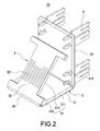
- FIG. 2 is a perspective view of the FPCB module of the invention
- FIG. 3 is a sectional view of the FPCB module of the invention.
- FIG. 4 is a perspective view of another embodiment of the FPCB module
- FIG. 5 is a sectional view of another embodiment of the FPCB module
- FIG. 6 is a perspective view of still another embodiment of the FPCB module.
- FIG. 7 is a sectional view of still another embodiment of the FPCB module.
- the connector 10 of the invention includes a front seat 1 and a flexible printed circuit board (FPCB) pin module 20 .
- the FPCB pin module 20 includes an FPCB 3 , a plurality of terminals 4 and a flexible support 5 .
- the connector 10 can be, but not limited to, an RJ45 connector.
- the front seat 1 is formed with a socket 11 and a room 12 for receiving the socket 11 .
- the connector 10 further includes a rear seat 2 located behind the front seat 1 .
- the rear seat 2 may be omitted according to actual requirements.
- the flexible circuit board (FPCB) pin module 20 is received in the room.
- the FPCB 3 has a fixing portion 31 , a connecting portion 32 bendingly extending from an edge of the fixing portion 31 and a terminal insertion portion 33 extending from another edge of the fixing portion 31 and corresponding to the socket 11 .
- the connecting portion 32 aslope to the fixing portion 31 , i.e., a bend portion 34 is formed between the fixing portion 31 and the connecting portion 32 .
- the terminal insertion portion 33 is perpendicular to the fixing portion 31 .
- the front side of the connecting portion 32 is provided with signal connection areas 321 , so that the FPCB 3 can replace conventional V-shaped terminals.
- the terminals 4 pass through and are fixed on the terminal insertion portion 33 .
- the terminals 4 are separately connected to the signal connection areas 321 through the FPCB 3 .
- the terminals 4 are eight in number and are separately located at four corners of the terminal insertion portion 33 .
- the flexible support is a plastic sheet and attached on the fixing portion 31 and the connecting portion 32 for supporting the connecting portion.
- the flexible support is a V-shaped sheet 51 composed of a horizontal section 511 , a slant section 512 and a bend section 513 therebetween.
- the horizontal section 511 , slant section 512 and bend section 513 are attached on the fixing portion 31 , connecting portion 32 and bend portion 34 , respectively. Additionally, the horizontal section 511 is further extended with a vertical section 514 attached on the terminal insertion portion 33 .
- V-shaped terminals can be replaced with the FPCB 3 .
- the terminals 4 are directly fixed on the FPCB 3 so that a soldering process of pins and terminals can be saved and the antenna effect can be avoided.
- the wiring arrangement can be balanced.
- the connecting portion 32 and a signal wire (not shown, disposed on the FPCB 3 ) are the same in width, impedance matching can be obtained. As a result, signal delay and crossover can be reduced.
- the FPCB 3 can be reinforced by the flexible support 5 , so that the connecting portion 32 can keep a good restoration ability.
- FIGS. 4-5 show another embodiment of the invention.
- the top end of the connecting portion 32 is extended with an extension portion 35 .
- the extension portion 35 is parallel to the fixing portion 31 and is extended with a vertical terminal inserting portion 36 .
- Four of the terminals 4 are fixed on the terminal insertion portion 33 and the other four are fixed on the terminal inserting portion 36 . This allows the FPCB pin module 20 to be applied in a 180° network socket (Keystone Jack).
- FIGS. 6-7 shows still another embodiment of the invention.
- the terminal insertion portion 33 is coplanar with the fixing portion 31 .
- the terminals 4 are fixed on the terminal insertion portion 33 . This allows the FPCB pin module 20 to be applied in a 90° network socket (Keystone Jack).
- the FPCB 3 is thinner than a hard PCB, the FPCB 3 can be bendable and applied in a limited space.
Landscapes
- Coupling Device And Connection With Printed Circuit (AREA)
Abstract
Description
-
- 1. Conventional V-shaped terminals can be replaced with the FPCB. The terminals are directly fixed on the FPCB so that a soldering process of pins and terminals can be saved and the antenna effect can be avoided.
- 2. By replacing conventional V-shaped pins with FPCB 3, the wiring arrangement can be balanced. The connecting
portion 32 and a signal wire (not shown, disposed on the FPCB 3) are the same in width, impedance matching can be obtained. As a result, signal delay and crossover can be reduced. - 3. The FPCB can be reinforced by the flexible support, so that the connecting
portion 32 can keep a good restoration ability. - 4. Because the FPCB is thinner than a hard PCB, the FPCB can be bendable and applied in a limited space.
Claims (9)
Priority Applications (1)
| Application Number | Priority Date | Filing Date | Title |
|---|---|---|---|
| US13/865,661 US8998650B2 (en) | 2013-04-18 | 2013-04-18 | Connector with FPCB pin module |
Applications Claiming Priority (1)
| Application Number | Priority Date | Filing Date | Title |
|---|---|---|---|
| US13/865,661 US8998650B2 (en) | 2013-04-18 | 2013-04-18 | Connector with FPCB pin module |
Publications (2)
| Publication Number | Publication Date |
|---|---|
| US20140315444A1 US20140315444A1 (en) | 2014-10-23 |
| US8998650B2 true US8998650B2 (en) | 2015-04-07 |
Family
ID=51729343
Family Applications (1)
| Application Number | Title | Priority Date | Filing Date |
|---|---|---|---|
| US13/865,661 Expired - Fee Related US8998650B2 (en) | 2013-04-18 | 2013-04-18 | Connector with FPCB pin module |
Country Status (1)
| Country | Link |
|---|---|
| US (1) | US8998650B2 (en) |
Cited By (4)
| Publication number | Priority date | Publication date | Assignee | Title |
|---|---|---|---|---|
| US20160036178A1 (en) * | 2014-08-04 | 2016-02-04 | Wilhelm Rutenbeck GmbH & Co.KG | Telecommunication or data-transmission jack |
| US9806477B2 (en) * | 2016-01-21 | 2017-10-31 | Wilhelm Rutenbeck Gmbh & Co. Kg | Jack for data and telecommunication system |
| US20180226760A1 (en) * | 2010-10-21 | 2018-08-09 | Panduit Corp. | Communications plug with improved crosstalk |
| US20240113482A1 (en) * | 2022-09-30 | 2024-04-04 | Ellax Corporation | Electrical connector structure |
Citations (5)
| Publication number | Priority date | Publication date | Assignee | Title |
|---|---|---|---|---|
| US7828603B1 (en) * | 2010-01-07 | 2010-11-09 | Yfc-Boneagle Electric Co., Ltd. | Electrical connector with crosstalk compensation |
| US7837513B2 (en) * | 2004-04-19 | 2010-11-23 | Belden Cdt (Canada) Inc. | Telecommunications connector |
| US7837511B2 (en) * | 2008-01-22 | 2010-11-23 | Hon Hai Precision Ind. Co., Ltd. | Electrical connector having improved connecting module |
| US7985101B2 (en) * | 2009-01-26 | 2011-07-26 | Commscope, Inc. Of North Carolina | RJ-45 style communications jacks that are configured to receive both RJ-45 and RJ-11 style communications plugs |
| US8128436B2 (en) * | 2009-08-25 | 2012-03-06 | Tyco Electronics Corporation | Electrical connectors with crosstalk compensation |
-
2013
- 2013-04-18 US US13/865,661 patent/US8998650B2/en not_active Expired - Fee Related
Patent Citations (5)
| Publication number | Priority date | Publication date | Assignee | Title |
|---|---|---|---|---|
| US7837513B2 (en) * | 2004-04-19 | 2010-11-23 | Belden Cdt (Canada) Inc. | Telecommunications connector |
| US7837511B2 (en) * | 2008-01-22 | 2010-11-23 | Hon Hai Precision Ind. Co., Ltd. | Electrical connector having improved connecting module |
| US7985101B2 (en) * | 2009-01-26 | 2011-07-26 | Commscope, Inc. Of North Carolina | RJ-45 style communications jacks that are configured to receive both RJ-45 and RJ-11 style communications plugs |
| US8128436B2 (en) * | 2009-08-25 | 2012-03-06 | Tyco Electronics Corporation | Electrical connectors with crosstalk compensation |
| US7828603B1 (en) * | 2010-01-07 | 2010-11-09 | Yfc-Boneagle Electric Co., Ltd. | Electrical connector with crosstalk compensation |
Cited By (7)
| Publication number | Priority date | Publication date | Assignee | Title |
|---|---|---|---|---|
| US20180226760A1 (en) * | 2010-10-21 | 2018-08-09 | Panduit Corp. | Communications plug with improved crosstalk |
| US11600960B2 (en) * | 2010-10-21 | 2023-03-07 | Panduit Corp. | Communications plug with improved crosstalk |
| US20160036178A1 (en) * | 2014-08-04 | 2016-02-04 | Wilhelm Rutenbeck GmbH & Co.KG | Telecommunication or data-transmission jack |
| US9413124B2 (en) * | 2014-08-04 | 2016-08-09 | Wilhelm Rutenbeck Gmbh & Co. Kg | Telecommunication or data-transmission jack |
| US9806477B2 (en) * | 2016-01-21 | 2017-10-31 | Wilhelm Rutenbeck Gmbh & Co. Kg | Jack for data and telecommunication system |
| US20240113482A1 (en) * | 2022-09-30 | 2024-04-04 | Ellax Corporation | Electrical connector structure |
| US12573797B2 (en) * | 2022-09-30 | 2026-03-10 | Ellax Corporation | Electrical connector structure |
Also Published As
| Publication number | Publication date |
|---|---|
| US20140315444A1 (en) | 2014-10-23 |
Similar Documents
| Publication | Publication Date | Title |
|---|---|---|
| CN102255179B (en) | The connector system that density increases | |
| US8764488B2 (en) | Connector having bridge member for coupling ground terminals | |
| CN101507053B (en) | Electrical connector system with spliced contact tails | |
| CN102891411B (en) | Connector mechanism for connecting board card | |
| CN212659718U (en) | plug electrical connector | |
| US9461423B2 (en) | Electrical connector | |
| US7086866B1 (en) | Circuit board mounted electrical connector | |
| US7614899B2 (en) | Electrical connector assembly | |
| US20080220656A1 (en) | Modular jack assembly having improved base element | |
| CN103682837A (en) | Electric connector | |
| US20120320551A1 (en) | Expansion structure | |
| US8998650B2 (en) | Connector with FPCB pin module | |
| CN105682356A (en) | Flexible circuit board assembly and electronic equipment | |
| CN104064893A (en) | Backboard and communication device | |
| US9627812B2 (en) | USB plug capable of being inserted face up and face down | |
| US10153573B1 (en) | Multi-purpose female metal terminal and female terminal connector | |
| US9077123B2 (en) | Electrical connector assembly with low profile | |
| WO2021036688A1 (en) | Circuit board assembly, backplane interconnection system and electronic device | |
| US9437988B2 (en) | Electrical connector | |
| US7402055B2 (en) | Circuit board type connector | |
| CN204538363U (en) | Electric connector | |
| US7044805B1 (en) | Pin contact installation assembly for a terminal | |
| US9089065B2 (en) | Electrical connector having a connector standoff | |
| CN102665373B (en) | Printed circuit board and manufacturing method thereof | |
| US8118600B2 (en) | Inserting connector, connector unit, and backplane |
Legal Events
| Date | Code | Title | Description |
|---|---|---|---|
| AS | Assignment |
Owner name: YFC-BONEAGLE ELECTRIC CO., LTD., TAIWAN Free format text: ASSIGNMENT OF ASSIGNORS INTEREST;ASSIGNORS:KU, YING-MING;CHEN, CHUN-CHIEH;REEL/FRAME:030244/0768 Effective date: 20130323 |
|
| STCF | Information on status: patent grant |
Free format text: PATENTED CASE |
|
| FEPP | Fee payment procedure |
Free format text: MAINTENANCE FEE REMINDER MAILED (ORIGINAL EVENT CODE: REM.); ENTITY STATUS OF PATENT OWNER: SMALL ENTITY |
|
| LAPS | Lapse for failure to pay maintenance fees |
Free format text: PATENT EXPIRED FOR FAILURE TO PAY MAINTENANCE FEES (ORIGINAL EVENT CODE: EXP.); ENTITY STATUS OF PATENT OWNER: SMALL ENTITY |
|
| STCH | Information on status: patent discontinuation |
Free format text: PATENT EXPIRED DUE TO NONPAYMENT OF MAINTENANCE FEES UNDER 37 CFR 1.362 |
|
| FP | Expired due to failure to pay maintenance fee |
Effective date: 20190407 |