US8997909B2 - Air cushion transport - Google Patents
Air cushion transport Download PDFInfo
- Publication number
- US8997909B2 US8997909B2 US14/001,937 US201214001937A US8997909B2 US 8997909 B2 US8997909 B2 US 8997909B2 US 201214001937 A US201214001937 A US 201214001937A US 8997909 B2 US8997909 B2 US 8997909B2
- Authority
- US
- United States
- Prior art keywords
- layer
- gas
- platform
- nmset
- stack
- Prior art date
- Legal status (The legal status is an assumption and is not a legal conclusion. Google has not performed a legal analysis and makes no representation as to the accuracy of the status listed.)
- Expired - Fee Related
Links
Images


Classifications
-
- B—PERFORMING OPERATIONS; TRANSPORTING
- B60—VEHICLES IN GENERAL
- B60V—AIR-CUSHION VEHICLES
- B60V1/00—Air-cushion
- B60V1/04—Air-cushion wherein the cushion is contained at least in part by walls
-
- B—PERFORMING OPERATIONS; TRANSPORTING
- B60—VEHICLES IN GENERAL
- B60V—AIR-CUSHION VEHICLES
- B60V1/00—Air-cushion
- B60V1/10—Air-cushion in which the curtain-forming nozzle or the vehicle base is shaped to create a vortex curtain
-
- B—PERFORMING OPERATIONS; TRANSPORTING
- B60—VEHICLES IN GENERAL
- B60V—AIR-CUSHION VEHICLES
- B60V1/00—Air-cushion
- B60V1/04—Air-cushion wherein the cushion is contained at least in part by walls
- B60V1/043—Air-cushion wherein the cushion is contained at least in part by walls the walls being flexible
-
- B—PERFORMING OPERATIONS; TRANSPORTING
- B60—VEHICLES IN GENERAL
- B60V—AIR-CUSHION VEHICLES
- B60V1/00—Air-cushion
- B60V1/11—Stability or attitude control
- B60V1/115—Stability or attitude control by ground or water engaging means, e.g. rudders or wheels
-
- B—PERFORMING OPERATIONS; TRANSPORTING
- B60—VEHICLES IN GENERAL
- B60V—AIR-CUSHION VEHICLES
- B60V1/00—Air-cushion
- B60V1/16—Flexible skirts
-
- B—PERFORMING OPERATIONS; TRANSPORTING
- B60—VEHICLES IN GENERAL
- B60V—AIR-CUSHION VEHICLES
- B60V3/00—Land vehicles, waterborne vessels, or aircraft, adapted or modified to travel on air cushions
- B60V3/02—Land vehicles, e.g. road vehicles
- B60V3/025—Land vehicles, e.g. road vehicles co-operating with a flat surface, e.g. transporting loads on platforms
-
- F—MECHANICAL ENGINEERING; LIGHTING; HEATING; WEAPONS; BLASTING
- F02—COMBUSTION ENGINES; HOT-GAS OR COMBUSTION-PRODUCT ENGINE PLANTS
- F02K—JET-PROPULSION PLANTS
- F02K99/00—Subject matter not provided for in other groups of this subclass
-
- F—MECHANICAL ENGINEERING; LIGHTING; HEATING; WEAPONS; BLASTING
- F25—REFRIGERATION OR COOLING; COMBINED HEATING AND REFRIGERATION SYSTEMS; HEAT PUMP SYSTEMS; MANUFACTURE OR STORAGE OF ICE; LIQUEFACTION SOLIDIFICATION OF GASES
- F25B—REFRIGERATION MACHINES, PLANTS OR SYSTEMS; COMBINED HEATING AND REFRIGERATION SYSTEMS; HEAT PUMP SYSTEMS
- F25B21/00—Machines, plants or systems, using electric or magnetic effects
- F25B21/02—Machines, plants or systems, using electric or magnetic effects using Peltier effect; using Nernst-Ettinghausen effect
Definitions
- the present disclosure is generally directed to the field of mobile transports systems, and more particularly to transport systems that hover using the ground effect.
- Hovercrafts are vehicles that travel over the surface of land or water using an air cushion produced by downwardly directed fans, maintained within a flexible skirt beneath the hull. Hovercraft can quickly carry heavy loads over land and water. However, in comparison to other types of motor vehicles, hovercrafts are large, noisy and dangerous. Operating a hovercraft in residential areas would produce an unacceptable level of noise and risk. Consequently, consumer-uses of hovercraft are limited.
- a movable support platform includes a platform, a skirt coupled to a periphery of the platform that provides an enclosed space below the platform that retains pressurized gas and a thrust propulsion device coupled to the platform for pressurizing gas in the enclosed space.
- the thrust propulsion device includes an array of gas-propelling devices, such as “distributed microthrusters” or “distributed thrusters”, that propel gas into the enclosed space below the platform.
- distributed thrusters is NMSET, an embodiment of which may include a first layer and a second layer and may be arranged in a stack, at least one through-hole in the stack. A surface of each of said layers is exposed in the interior of the through hole.
- a heating/cooling device can selectively heat and/or cool the layers of the individual gas-propelling devices.
- FIG. 1 shows a heat pump. This can be a Peltier slab, a slab driven by thermionic emission, or any other suitable means.
- FIG. 2 shows gas flow patterns around the heat pump of FIG. 1 .
- FIG. 4 shows net forces on a stack of Nano Molecular Solid-state Electrodynamic Thrusters (NMSET) with sawtooth geometry.
- NMSET Nano Molecular Solid-state Electrodynamic Thrusters
- FIG. 5 shows gas particle velocities around a stack of NMSET with sawtooth geometry.
- FIG. 6 shows the thermo-tunneling enhanced Peltier effect.
- FIG. 7 shows a stack of NMSET with a parabolic geometry.
- FIG. 8 shows gas flow patterns around the stack of NMSET of FIG. 7 and the momentum space of the gas.
- FIG. 9 shows a stack of NMSET with a triangular geometry.
- FIG. 10 shows the momentum space of the gas around the stack of NMSET with a triangular geometry.
- FIG. 11 shows a stack of NMSET with a sawtooth geometry.
- FIG. 12 shows the momentum space of the gas around the stack of NMSET with a sawtooth geometry.
- FIG. 13 shows a cross sectional view of an NMSET with an internal arrangement of solid state heat pumps. These heat pumps can be driven by Peltier effect, thermionic emission, or any other suitable means.
- FIG. 14 shows a perspective view of NMSET with an internal solid state heat pump arrangement on FIG. 13 .
- FIG. 15 shows a perspective view of an NMSET with an external solid state heat pump arrangement.
- FIG. 16 shows a cross sectional view of NMSET with an external solid state heat pump arrangement of FIG. 15 .
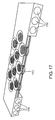
- FIG. 17 shows a perspective view of NMSET with an external non-solid state heat pump arrangement.
- FIG. 18 shows a cross sectional view of a staged NMSET arrangement.
- FIG. 19 shows NMSET with a straight geometry.
- FIG. 20 shows an exemplary method of manufacturing NMSET.
- FIG. 21 shows another exemplary method of manufacturing NMSET.
- FIG. 22 is a side cross-sectional view illustrating a thermal transpiration device.
- FIG. 23 is a side cross-sectional view illustrating the operation of a thermal transpiration device.
- FIG. 24 is a side cross-sectional view of a thermal transpiration device with one extended layer and angled walls.
- FIG. 25 is a top cross-sectional view of the thermal transpiration device illustrated in FIG. 24 .
- FIG. 26 is a side cross-sectional view of a thermal transpiration device with one extended layer and wet or dry etched walls.
- FIG. 27 is a top cross-sectional view of the thermal transpiration device illustrated in FIG. 26 .
- FIG. 28 is a side cross-sectional view of a thermal transpiration device with two extended layers and angled walls.
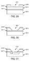
- FIG. 29 is a cross-sectional view of a beginning construction of one embodiment of a thermal transpiration device.
- FIG. 30 is a cross-sectional view of the continued construction of the thermal transpiration device shown in FIG. 29 .
- FIG. 31 is a side cross-sectional view of the continued construction of the thermal transpiration device shown in FIG. 30 .
- FIG. 32 is a cross-sectional view showing further construction of the thermal transpiration device shown in FIG. 31 .
- FIG. 33 is a cross-sectional view showing the islands formed in the construction of the thermal transpiration device.
- FIG. 34 is a top view of an embodiment of a control system in accordance with the present disclosure.
- FIG. 35 is a top view of the control system illustrated in FIG. 34 showing the operation of supplying power to a set of connection paths.
- FIG. 36 is a top view of the control system illustrated in FIG. 34 showing the effects of a fault in one of the power lines.
- FIG. 37 is a top view of an embodiment of a control system in accordance with the present disclosure that includes fault tolerance features.
- FIG. 38 is a top view of another embodiment of the control system, designed to control larger arrays of distributed thrusters, than the control system in FIG. 34 .
- FIG. 39 is top view of another preferred embodiment of the control system, designed to control larger arrays of distributed thrusters than the control system in FIG. 38 .
- FIG. 40 a is a top view of another embodiment of the present disclosure, showing primary and secondary affected areas when the control system activates the target area.
- FIG. 40 b is a cross sectional view of the embodiment shown in FIG. 40 a , with intersecting power lines located on the heated side of the device.
- FIG. 40 c is another cross sectional view of the embodiment shown in FIG. 40 a , with intersecting power lines on each side of the device.
- FIG. 41 b is a cross sectional view of the embodiment shown in FIG. 41 a , with intersecting power lines located on the heated side of the device.
- FIG. 42 b a top view of a middle insulating layer placed on top of FIG. 42 a.
- FIG. 42 c is a top view a grid structure of a power supply line and a plurality of branch lines that is placed on top of FIG. 42 b and creates a plurality of target points from a single power line intersection point to be used with the control system.
- FIGS. 43 and 44 are schematic diagrams for creating a temperature gradient.
- FIG. 46 is a top cross-sectional view of a plurality of thruster regions arranged in horizontal and vertical rows in accordance with the present disclosure.
- FIG. 47 is a top cross-sectional view of a plurality thruster regions showing the heating effect of adjacent regions when a thruster region is activated.
- FIG. 49B is a top view of the air cushion transport.
- FIGS. 51A and 51B illustrate an exemplary embodiment of the transport in which the skirt is formed of a plurality of distributed micro thruster surfaces.
- one example of distributed thrusters is an apparatus described herein that may be referred to as a Nano Molecular Solid-state Electrodynamic Thruster (NMSET).
- NMSET Nano Molecular Solid-state Electrodynamic Thruster
- the basis of operation of NMSET makes it possible to apply NMSET in the fields of, for example, propulsion, adhesion, compression and refrigeration, depending on the manner in which an NMSET is employed.
- NMSET and related distributed thrusters devices provide lightweight, compact, energy-efficient creation of a gas pressure differential with adjustable flow velocity.
- distributed thrusters such as NMSET can offer one or more of the following improvements in the field of gas propulsion:
- distributed thrusters such as NMSET
- the process can be reversible, as the only step required to reverse the adhesion is to cut power to the system, in some embodiments.
- Using such a system can provide further benefit over electrostatic adhesion in that such a system does not require a material to be adhered to be flat or conductive, and does not leave behind residue. Compared to other mechanical adhesion processes, using such a system may not require a surface being adhered to be pretreated.
- Reduction of entropy in a gas by NMSET may be represented by a transformation A in the momentum space k of the gas.
- A can be expressed in a matrix once a set of suitable bases is chosen for the momentum space k. If the expectation value of the transformed momentum space Ak is nonzero, the NMSET receives a net momentum in the opposite direction of the expectation value due to the conservation of momentum.
- NMSET may be optimized for more efficient functioning.
- the geometry of NMSET affects the transformation matrix A.
- a geometry that produces a matrix A essentially equal to an identity matrix I does not create a net momentum bias (i.e. will not make the transformed momentum space Ak have a nonzero expectation value). Rather, gas vortexes may be generated.
- Geometries that result in larger eigenvalues of A tend to imply a more efficient function, e.g., that more momentum is carried by gas particles moving in a particular direction.
- Transformation caused by the heat pump 100 to the momentum space k of the gas can be expressed by a Hermetian matrix A.
- a gas particle molecule or atom
- the gas particle rebounds off at a higher velocity than before the collision.
- the gas particle collides with the upper layer 101 , assuming the collision is diabatic, the gas particle rebounds off the upper layer 101 at a reduced velocity than before the collision.
- the heat pump 100 feels a net force in the y direction. In other words, the lower layer 102 heats and thus increases pressure of the gas below the lower layer 102 , while the upper layer 101 cools and thus decreases the pressure of the gas above the upper layer 101 .
- a temperature differential between layers of material or more precisely, between two opposing surfaces is generally required for NMSET or related device to operate.
- a temperature differential can be established in a solid-state electrodynamic mechanism, i.e., the “SE” of NMSET.
- SE solid-state electrodynamic mechanism
- the devices and methods described here are not limited to electronic or purely solid state devices.
- a temperature differential may be established by conduction of heat from combustion using a fluid coolant, exothermic chemical reaction, or other chemical source.
- a temperature differential may be established by simple resistive heating, by the Peltier effect, by thermionic emission, by the thermo-tunneling enhanced Peltier effect, or by any other suitable means, such as explained below.
- a means by which the temperature differential is established between two objects can be phenomenologically described by two characteristics: entropy-reduction (heat transfer between the two objects), and diabaticity (total heat transfer between environment and the two objects).
- the Peltier effect can be used to establish a temperature differential.
- the Peltier effect occurs when an electric current is applied through a loop composed of two materials with different Peltier coefficients joined at two junctions. Depending on the direction of the electric current, heat flows from one junction to the other, causing a temperature differential to be established between the junctions.
- the Peltier effect can be understood as follows: Heat capacity of charge carriers in a material is characterized by the Peltier coefficient ⁇ , which is the amount of heat carried per unit charge carriers in the material. When an electric current I flows through a junction of material A with Peltier coefficients ⁇ A and material B with Peltier coefficient ⁇ B , the amount heat carried by charge carriers to the junction in a unit time is I ⁇ ( ⁇ A ⁇ B ).
- Peltier effect reduces entropy locally and is adiabatic. Assuming Joule heating and or Carnot cycle inefficiencies can be ignored, in the Peltier effect, heat is transferred from one junction to another, but no heat is added into the loop of the two materials. This entropy reduction can provide for advantages in the stackability of NMSET and related devices. Consequently, the Peltier effect lends itself particularly well to some embodiments.
- a power source drives an electric current between two surfaces.
- Charge carriers such as electrons and/or holes carry heat as they flow in the electric current, and thus create a temperature differential between the two surfaces. Entropy is reduced as the temperature differential is established.
- Phonon flow reduces the temperature differential established by the Peltier effect. If phonons are permitted to flow freely (i.e., infinite thermal conductivity or zero heat capacity), their flow will cancel the temperature differential established by the Peltier effect. Efficiency of the Peltier effect can be increased by reducing electrical resistance and thermal conductance.
- thermo-tunneling enhanced Peltier effect (or thermotunnel cooling).
- FIG. 6 shows a diagram of the thermo-tunneling enhanced Peltier effect. Charge carriers 601 can tunnel through a vacuum gap 602 .
- thermo-tunneling enhanced Peltier effect is generally only significant at high temperatures or voltages, unless enhanced by choice of surface geometry and materials that can restrict behavior of charge carriers near the vacuum gap and increase tunneling probability.
- suitable surface coatings and structures can function as a filter that do not allow low energy states of charge carriers but only high energy states of charge carriers near the vacuum gap.
- a temperature differential can be created and maintained by field-enhanced thermionic emission.
- Thermionic emission is a heat-induced flow of charge carriers over a potential-energy barrier.
- the charge carriers can be electrons or ions (i.e., thermions).
- the potential-energy barrier acts like a dam, in that it withholds carriers with thermal energy less than its height and allows carriers with thermal energy greater than its height to flow over. When the overflowing carriers pass the potential-energy barrier, heat is carried away with them. The carriers left behind the potential-energy barrier re-thermalize (redistribute in energy) to a lower temperature.
- Thermionic emission typically requires an operating temperature of several hundred degrees Celsius so that a non-negligible fraction of the carriers has thermal energies great enough to overcome the potential-energy barrier.
- An electrical field can assist thermionic emission by reducing the height of the potential-energy barrier and reducing the required operating temperature.
- a temperature differential in NMSET or related device can also be established by using resistive heating (explained below) and/or by suitable chemical processes.
- some cooling means can also be provided, such as a heat sink exposed to atmosphere. No matter what cooling means is used, the temperature differential is more pronounced if warmer surfaces of the device are not cooled as efficiently as cooler surfaces, which can be achieved, for example, by thermal insulation.
- the production of net thrust may be thought of as the transfer of the reduced entropy from an established temperature differential to a gas.
- a temperature differential between a hot and a cold layer can be established by a suitable means such as the Peltier effect.
- a suitable means such as the Peltier effect.
- Particles of the gas will impact the hot and cold layers with equal probabilities, and their interaction with these layers will have consequences on local momentum space of the gas near surfaces of the hot and cold layers.
- the local momentum space of the gas very close to a surface of the hot and cold layers has nonzero expectation value when the gas and the surface have different temperatures.
- the heat pump 100 can have at least one through hole between the layer 101 and 102 .
- Gas spontaneously flows from the layer 101 to the layer 102 through the hole which enables higher heating rate of the gas.
- Such preferential flow of gas is referred to as thermal transpiration.
- thermal transpiration causes the gas to flow from the layer 101 to the layer 102 through the hole, if the following equation is satisfied:
- thermodynamic equilibrium can be achieved approximately in the mean free time (the time it takes a gas particle to travel the mean free path).
- the characteristic scale of individual features of NMSET and related devices may be nanoscale, i.e., the “NM” of NMSET.
- NM the characteristic scale of individual features of NMSET and related devices
- the methods and devices described here are not limited to nanoscale embodiments.
- the mean free path parameter is dependent on gas density so that in some embodiments and uses, larger scale features may be employed.
- pluralities of NMSET and related device elements can be combined to provide action over a large surface.
- distributed thrusters such as NMSET may advantageously be arranged in arrays and or arrays of arrays to provide directed movement of gas over across large surfaces, for example, as illustrated in FIGS. 15 , 16 and 17 .
- FIG. 18A illustrates a cross sectional view of an array of staged distributed thrusters such as NMSET arrangements 1800 .
- Each staged arrangement 1800 is composed of stages 1810 , 1820 , 1830 of in the form of concentric half-spheres containing arrays of distributed thrusters such as NMSET 1840 , 1850 , 1860 illustrated in blow-up in FIGS. 18B-18D .
- Individual distributed thruster apertures 1845 , 1855 , 1865 in each stage increase in optimal size and thickness in accordance with the decreasing ambient pressure that would be experienced at each previous stage in operation.
- Box 300 comprises two planar hot walls 302 parallel to each other, and two planar cold walls 301 parallel to each other and perpendicular to the hot walls 302 . If the box 300 is comparable in size to the mean free path of the gas particles therein and the walls 301 and 302 are perfectly specular, the gas particles can reach thermal equilibrium with the cold walls 301 and the hot walls 302 independently. This is because surface normals of the walls are only shared between the two cold walls 301 or between the two hot walls 302 , but not between a cold wall 301 and a hot wall 302 .
- Knudsen numbers are usually not perfectly specular.
- specular surface properties exist very strongly in some materials so that there are angles for which convective flows in corners may be reduced. This effect is generally observed when the Knudsen numbers are large, which is a preferred condition for NMSET and related devices, particularly in nanoscale embodiments.
- the Knudsen number (Kn) named after Danish physicist Martin Knudsen (1871-1949), is a dimensionless number defined as the ratio of the molecular mean free path to a representative physical length scale.
- the representative physical length scale is taken to be the order of magnitude of the aperture diameter of the device, i.e., the representative physical scale length is, for example, a nanometer if the aperture is measured in nanometers and a micrometer if the aperture is measured in micrometers.
- the Knudsen number is preferably greater than 0.1, or greater than 1, or greater than 10.
- Performance of NMSET with a specific geometry can be simulated by a Monte-Carlo method for optimization.
- a simulation for NMSET or related device with any given geometry starts with a group of gas particles with random initial positions and momenta around the device. Positions and momenta of these particles after a small time interval are calculated from the initial positions and momenta, using known physical laws, parameters such as temperature, pressure, chemical identity, geometry of the device, interaction between surfaces of the device and the gas particles.
- the simulation is run through a chosen number of iterations and simulation results are analyzed.
- the geometry of the device can be optimized using simulation results.
- a device is constructed using the results of the simulation analysis.
- a simulation can be represented in the following table:
- a perturbation model M is evolved through a number (k) of iterations.
- M is initialized to an empty set, indicating no solution knowledge.
- a loop is started in which the search parameters generate an arbitrary element from the definite search space P and the prior learned knowledge M is used to perturb P.
- the specific algorithm used to perturb as an implementation detail.
- M should ideally be identical among all nodes, but this is not necessary due to the inherently stochastic nature of the process.
- the step of EVOLVE_MODEL which actually runs the Monte-Carlo simulation is the most computationally expensive of all by far and offers a lot of time to synchronize M.
- parameters depend on the environment.
- the parameters that the user can specify include the following:
- the Monte-Carlo simulation can be run with periodic bounds in all axes.
- particles encountering the periodic bound are stochastically thermostatted according to temperature and pressure settings in order to simulate ambient conditions.
- particle velocities are unmodified in order to simulate a periodic ensemble of identical device assemblies along that direction.
- the simulation may be run in two dimensions to reduce the computational complexity of the simulation.
- a three dimensional simulation should give similar results where the modeled device has cylindrical symmetry. Note that in general, a simulator does not have to use the periodicity as indicated here and may not specify any boundaries at all; they are only defined as a computational convenience.
- potential device geometries can be evaluated in consideration of the conditions under which a device will be used and known surface reflection properties of the material from which it will be constructed. Geometrical parameters can be optimized by analyzing results from simulation before the geometry is actually used in manufacture of NMSET and related devices.
- FIG. 19 shows an embodiment of NMSET or related device 1900 with a straight geometry.
- the device 1900 comprises a hot layer 1902 and a cold layer 1901 .
- the terms “hot layer” and “cold layer” mean that these layers have a temperature difference therebetween, not that the “hot layer” is necessarily hotter or the “cold layer” is necessarily colder, than a gas that the NMSET or related device is immersed in.
- At least one straight through hole 1910 extends through all layers of the device 1900 and preferably has a similar cross-sectional shape and size for each set of layers.
- the straight through hole 1910 can have any cross-sectional shape such as circular, slit, and comb.
- a total length 1910 L (i.e. a distance from one entrance to the other entrance) of the straight through hole 1910 is up to 10 times, up to 5 times or up to 2 times of the mean free path of a gas in which the device 1900 is immersed.
- the mean free path of air at the standard atmosphere pressure is about 55 nm. At higher altitude, the mean free path of air increases.
- the total length 1910 L is preferably not greater than 1500 nm and, depending on the application, more preferably not greater than 550 nm, not greater than 275 nm, or not greater than 110 nm.
- a temperature differential between the hot layer 1902 and the cold layer 1901 is preferably at least 0.5° C., more preferably at least 30° C., more preferably at least 50° C., and most preferably at least 100° C.
- the hot layer 1902 and the cold layer 1901 may be separated by a gap therebetween for thermal isolation.
- the gap preferably is a vacuum gap and/or contains a thermal insulator.
- the gap contains a plurality of thin pillars made of a good thermal insulator such as silicon dioxide.
- the device 1900 has preferably at least 10 straight through holes per square centimeter.
- a total perimeter length of all the straight through holes of the device 1900 per square centimeter is preferably at least two centimeters.
- FIG. 7 shows an embodiment of an NMSET or related device 700 with a parabolic geometry.
- alternating hot layers 702 and cold layers 701 are stacked.
- each hot layer 702 and cold layer 701 has a straight through hole. All the holes are aligned.
- the hole in each hot layer 702 has the similar size as the hole in the cold layer 701 immediately above, and is smaller than the hole in the cold layer 701 immediately below.
- Each cold layer 701 is colder than its immediate adjacent hot layers 702 and each hot layer 702 is hotter than its immediate adjacent cold layers 701 .
- a surface 702 a of each hot layer 702 which has a surface normal in the ⁇ y direction, is exposed.
- NMSET adiabatic or isobaric, but not both.
- FIG. 8 An approximation of gas flow in NMSET or related device with the parabolic geometry is shown in FIG. 8 .
- the momentum space of the gas is skewed such that the expectation value of the momentum points to the ⁇ y direction.
- the NMSET with the parabolic geometry may not suffer in its efficiency from the gas undergoing a change in volume, as long as the amount of heat added to the gas is sufficient to prevent the formation of vortexes.
- a device suffers in its efficiency from higher total entropy, i.e., the eigenvectors of the momentum space of the gas are not as far apart if the gas has to expand, but supplying heat at small scales is typically easier than carrying it away.
- the triangular geometry detailed in FIG. 9 is a partial optimization of the parabolic geometry for adiabatic flows. In this case, the gas is not permitted to experience a sufficient expansion to trigger large-scale vortex generation. Furthermore, because the apertures do not change size, a triangular arrangement such as this one may be easily stacked.
- the momentum space of this triangular geometry is more efficiently biased, as is illustrated in FIG. 10 .
- the exposed hot and cold surfaces meet at preferably a 90-degree angle; however, a source of inefficiency arises when particles carry heat back and forth between surfaces across the center gap.
- FIG. 9 shows a stack 900 of NMSET or related device with the triangular geometry.
- Each device in the stack 900 comprises a hot layer 902 and a cold layer 901 of equal thickness.
- the temperature differential between the cold and hot layers 901 and 902 can be established by any suitable means such as the Peltier effect or any other heat pump.
- Each device has a through hole 903 .
- Each though hole 903 has approximately a 45° chamfer ( 9031 and 9032 ) on each entrance.
- the surface of the chamfers 9031 and 9032 is, for example, from 1.40 to 1.42 times of the thickness of the cold and hot layers 901 and 902 , not including modifications to the acute angles for structural considerations.
- the through holes 903 in all layers in the stack 900 are aligned.
- the temperatures of the hot layers 902 in a device in the stack 900 do not increase monotonically from one side of the stack to the other side.
- the temperatures of the cold layers 901 in a device in the stack 900 do not decrease monotonically from one side of the stack to the other side.
- each cold layer 901 is colder than its immediate adjacent hot layers 902 and each hot layer 902 is hotter than its immediate adjacent cold layers 901 .
- the hot and cold surfaces of the triangular arrangement may not come to a fine point.
- FIG. 11 shows a stack 1100 of NMSET or related device with a sawtooth geometry.
- Each device in the stack 1100 comprises a hot layer 1102 with a thickness of t h and a cold layer 1101 with a thickness t c .
- the temperature differential between the cold and hot layers 1101 and 1102 can be established by any suitable means such as the Peltier effect or any other heat pump.
- Each device has a through hole 1103 . In the illustrated device, each through hole 1103 has a chamfer 11031 at the entrance on the side of the cold layer 1101 , and a chamfer 11032 at the entrance on the side of the hot layer 1102 .
- An angle between the chamfer 11031 and a center axis of the through hole 1103 is ⁇ 1 ; an angle between the chamfer 11032 and a center axis of the through hole 1103 is ⁇ 2 .
- the sum of ⁇ 1 and ⁇ 2 is preferably from 75° to 105°, more preferably from 85° to 95, and more preferably from 88° to 92°.
- the ratio of t c to t h is substantially equal to the ratio of cotangent of ⁇ 1 to cotangent of ⁇ 2 .
- ⁇ 2 is preferably from 70° to 85°.
- the through holes 1103 in all layers in the stack 1100 are aligned. Temperatures of the hot layers 1102 in each device in the stack 1100 do not increase monotonically from one side of the stack to the other side. Temperatures of the cold layers 1101 in each device in the stack 1100 do not decrease monotonically from one side of the stack 1100 to the other side. Each cold layer 1101 is colder than its immediate adjacent hot layers 1102 and each hot layer 1102 is hotter than its immediate adjacent cold layers 1101 .
- the sawtooth geometry shown in FIG. 11 offers an improvement over the triangular geometry in that all hot layers 1102 are preferably oriented in nearly the same direction (i.e., ⁇ 2 is preferably nearly 90°). This reduces direct interaction between hot and cold layers 1102 and 1101 across the through hole 1103 , and improves overall efficiency.
- device slices on opposite sides of a cross section have a magnitude of 1/ ⁇ square root over (2) ⁇ in the y axis because their separation angle 90 degrees. This limits the efficiency of entropy reduction, as some of the entropy is going to be neutralized in direct inter-surface interaction.
- the hot layers 1102 not only share no basis with the adjacent cold layers 1101 , but also share very little basis with hot and cold layers across the through hole 1103 . This combined property makes the sawtooth geometry more efficient than the triangular geometry.
- each element in the device geometry acts both as a particle director and as the entropy reducer.
- the hot and cold plates are made of materials with different Peltier coefficients. Electrical current is made to flow between the cold and hot plates. This flow of current carries with it Peltier heat, establishing the temperature differential necessary to operate the device.
- piezoelectric spacers can be disposed between device elements to maintain the separation gaps therebetween.
- FIGS. 13 and 14 A cross section of NMSET or related device according to an embodiment with an internal Peltier arrangement is detailed in FIGS. 13 and 14 . All hot layers 1302 are connected. All cold layers 1301 are connected. Electric current flows through a Peltier device interposed between the cold and hot layers to establish a temperature differential. The thinner the layers are, the higher the electric current is necessary.
- NMSET or related device with the internal Peltier arrangement can make it easier to reduce the size of the device.
- a single stack such as the one shown in FIG. 14 can be fully functional to generate thrust.
- NMSET or related device with the internal heat pump are further suitable for use in microelectromechanical systems (MEMs) that emphasize the highest degree of granularity.
- MEMs microelectromechanical systems
- the temperature differential can be generated by field-enhanced thermionic emission. As shown in FIG. 19 , an electrical field can be established between the layers 1901 and 1902 such that charge carriers thermally emitted from the cold layer 1901 carry heat from the cold layer 1901 to the hot layer 1902 .
- the temperature differential can be generated by a heat pump, such as a Peltier device external to NMSET or related device.
- a heat pump such as a Peltier device external to NMSET or related device.
- This Peltier device arranged in a checker board fashion is thermally coupled to NMSET or related device stack 1500 via interface layers 1510 and 1520 as detailed in FIGS. 15 and 16 .
- a device with an external Peltier device has the benefit of separating the materials used to generate gas flow from the materials used to generate the temperature differential. From an engineering standpoint this may be desirable, as the materials suitable for a heat pump may not be suitable for microstructures, or vice versa. In addition, an external heat pump can be made larger and more efficient, and may require less current to establish a sufficient temperature differential.
- Piezoelectric spacers can be used between layers.
- Materials suitable for use in NMSET preferably are strong enough to mechanically withstand thermal expansion and contraction, and/or preferably have very small expansion coefficients. Otherwise, holes in the layers could become misaligned, which could reduce efficiency.
- a source of radiation may be directed toward a heat absorbing surface in thermal communication with the hot layer of NMSET or related device.
- a source of radiation may be directed toward a heat absorbing surface in thermal communication with the hot layer of NMSET or related device.
- more care is preferably taken to ensure that the NMSET or related device does not overheat.
- NMSET and related devices may be constructed of a wide range of materials. In various aspects, properties of materials may be exploited in combination with desirable geometries.
- Specular reflection of gas molecules is a preferred property of the materials which form the gas-exposed surfaces of NMSET or related device, e.g. the heated and cooled surfaces which are in contact with flowing gas. Specular reflection is the mirror-like reflection of light, or in this case gas particles, from a surface. On a specular surface, incoming gas particles at a single incident angle are reflected from the surface into a single outgoing angle. If the incoming gas particles and the surface have the same temperature, the incident angle and the outgoing angle with respect to the surface normal are the same. That is, the angle of incidence equals the angle of reflection.
- a second defining characteristic of specular reflection is that incident, normal, and reflected directions are coplanar. If the incoming gas particles and the surface are not at the same temperature and the reflection is diabatic (i.e. with heat exchange between the gas particles and the surface), the angle of reflection is a function of heat transferred between the surface and the gas particles.
- the degree of specularity of a material may be represented by a reflection kernel (such as the Cercignani-Lampis kernel) which is defined as the probability density function of reflected state of the gas particles per unit volume of the phase space. Details of the reflection kernel are disclosed in “Numerical Analysis of Gas-Surface Scattering Effect on Thermal Transpiration in the Free Molecular Regime”, Vacuum , Vol. 82, Page 20-29, 2009, and references cited therein, all of which are hereby incorporated by reference.
- a reflection kernel such as the Cercignani-Lampis kernel
- Individual hot and cold layers may also be constructed of one or more structural elements which can comprise structural materials, e.g. a means for conferring rigidity, thermal conductive material, e.g. a means for heat transfer to and from a temperature differential generating means, and atomic reflection material, e.g. means for providing a desirable reflection kernel properties.
- structural materials e.g. a means for conferring rigidity
- thermal conductive material e.g. a means for heat transfer to and from a temperature differential generating means
- atomic reflection material e.g. means for providing a desirable reflection kernel properties.
- individual hot and cold layers may be constructed of layered composites of such materials.
- materials suitable for construction of NMSET or related device can include titanium, silicon, steel, and/or iron. Titanium is light weight and possesses a hexagonal crystalline structure. Interfaces of titanium may be created at orthogonal angles without crystalline warping and therefore no stress limit. Material costs of titanium are high. Silicon is inexpensive and has well understood properties and processes for machining. The crystalline structure of silicon is diamond cubic. Steel is cheaper than titanium, possesses a cubic crystalline structure, and is highly resistant to gaseous intrusion. Iron is cheaper than steel and has a crystalline form which makes it suitable for application in NMSET and related devices.
- a method of manufacturing an NMSET or related device comprises: (a) providing a suitable substrate 2001 such as, for example, amorphous silicon, crystalline silicon, ceramic, etc., the substrate preferably having a thickness of 500 to 1500 microns, however thinner and thicker substrates are possible; (b) depositing a first layer 2002 , a mostly sacrificial layer, preferably an electrical insulator, such as, for example, silicon dioxide, the first layer 2002 preferably having a thickness of 200 nm to 50 microns, however thinner and thicker layers are possible. Furthermore, depending on the area of the substrate window 2001 a , it is advantageous for this layer to have a tunable stress level.
- Such layer can be made of, for example, wax, photoresist, or silicon dioxide substrate attached to the fifth layer 2006 via thermal release tape, the sixth layer 2007 preferably having a thickness of 500 to 1500 microns, however, other thicknesses are contemplated; (j) forming through holes 2001 a in the substrate 2001 by photolithography and etching the substrate 2001 , such that at least one discrete island of the first layer 2002 is exposed therein, the through holes 2001 a having any suitable shape such as, for example, hexagons, squares and circles, the through holes 2001 being arranged in any suitable pattern such as, for example, a hexagonal grid, square grid and a polar grid; (k) removing exposed discrete islands by etching until portions of the fourth layer 2005 there above are exposed; (l) removing exposed portions of the fourth layer 2005 by etching until portions of the fifth layer 2006 there above are exposed; (m) removing exposed portions of the fifth layer 2006 by etching; (n) partially removing the fourth layer 2005 by etching laterally such that the second layer 2003
- a method of manufacturing an NMSET or related device comprises: (a) providing a suitable substrate 2101 such as, for example, amorphous silicon, crystalline silicon, ceramic, etc., the substrate preferably having a thickness of 500 to 1500 microns; however thinner and thicker substrates are possible; (b) depositing a first layer 2102 , a mostly sacrificial layer, preferably an electrical insulator such as, for example, silicon dioxide, the first layer 2102 preferably having a thickness of 50 nm to 1000 nm; however thinner and thicker layers are possible. Furthermore, depending on the area of the substrate window 2101 a , it is advantageous for this layer to have a tunable stress level.
- a suitable substrate 2101 such as, for example, amorphous silicon, crystalline silicon, ceramic, etc.
- FIG. 22 is a side cross-sectional view illustrating a thermal transpiration device, such as NMSET or related device, shown generally at 2204 .
- the thermal transpiration device includes a cold side membrane 2202 and a hot side membrane 2201 , with a thermal insulator 2200 provided in between.
- the thermal insulator 2200 may be formed of a vacuum, which can be achieved, for example, via the Venturi effect.
- the thermal transpiration device 2204 includes a thickness 2203 defined by the cold side membrane 2202 , the thermal insulator 2200 and the hot side membrane 2201 .
- FIG. 23 is a side cross-sectional view illustrating the operation of a thermal transpiration device, shown generally at 2309 .
- the device 2309 includes a hotter layer 2301 , a colder layer 2302 , with a thermal insulator 2300 provided there between. Apertures 2308 are formed in the device 2309 in a manner as previously described.
- the thermal transpiration device 2309 includes a thickness 2303 defined by the colder layer 2302 , the thermal insulator 2300 and the hotter layer 2301 .
- the thermal insulator 2300 can be formed of a vacuum, which can be achieved, for example, via the Venturi effect.
- Colder gas particles 2304 which have a mean free path (average distance traveled before hitting another particle) shown by radius 2305 , enter the aperture 2308 , or the edge thereof, and collide with other particles, thus exchanging energy.
- Hotter gas particles 2306 which have a mean free path shown by radius 2307 , collide into the hotter layer 2301 , thus gaining energy in the process and imparting a positive momentum force.
- the colder gas particles 2304 reduce the temperature of the hotter gas particles 2306 , which collide back into the hotter layer 2301 , thus gaining energy and imparting a positive momentum force and increased pressure on the hot layer 2301 .
- FIGS. 24 and 25 are respective side and top cross-sectional views of a thermal transpiration device, shown generally at 2414 , with one extended layer having angled walls.
- the device 2414 includes a hotter layer 2401 and a colder layer 2402 , with a thermal insulator 2400 provided there between.
- the thermal insulator 2400 can be formed as a vacuum, which can be achieved, for example, via the Venturi effect.
- the total thickness of the device 2414 is indicated by reference number 2403 , and is defined by the colder layer 2402 , the thermal insulator 2400 and the hotter layer 2401 .
- Apertures 2408 are provided in the device 2414 , forming angled walls 2415 in the hotter layer 2401 , in a manner as previously described.
- the apertures 2408 , and/or edges thereof, aid in defining a hotter surface 2409 , a colder surface 2410 , an active area 2411 generally where thermal transpiration occurs, and a support area 2412 .
- the angle 2413 of the hotter surface 2409 is less than 90-degrees in order to form the angled walls 2415 .
- FIGS. 24 and 25 illustrate the extended layer having angled walls as being the hotter layer 2401 , one skilled in the art will appreciate that the colder layer 2402 could be implemented as the extended layer having angled walls as an acceptable alternative.
- Reference number 2605 indicates the mean free path radius of colder gas particles 2604 .
- Reference number 2607 indicates the mean free path radius (the average distance traveled before hitting other particles) of hotter gas particles 2606 .
- the colder gas particles 2604 enter the aperture 2608 , or the edge thereof, and collide with other particles, thus exchanging energy.
- the hotter gas particles 2606 collide into the hotter layer 2601 at the outer edge thereof or at the wet-etched surface 2614 , thus gaining energy in the process and imparting a positive momentum force.
- the colder gas particles 2604 reduce the temperature of the hotter gas particles 2606 , which collide back into the hotter layer 2601 thus gaining energy and imparting a positive momentum force and increased pressure on the hot layer 2601 .
- Apertures 2808 are provided in the device 2816 , forming angled walls 2817 and 2818 in the hotter 2801 and colder 2802 layers, respectively, in a manner as previously described.
- the apertures 2808 , and/or edges thereof, aid in defining a hotter surface 2809 , a colder surface 2810 , an active area 2811 generally where thermal transpiration occurs, a support area 2812 for the hotter layer 2801 , and a support area 2815 for the colder layer 2802 .
- the angle 2819 of both the hotter 2809 and colder 2810 surfaces are less than 90-degrees in order to form the angled walls 2818 and 2817 , respectively. While the angles 2819 of the hotter 2809 and colder 2810 are shown in FIG. 28 as being approximately the same angle, the hotter 2809 and colder 2810 surfaces may be angled at different angles as an acceptable alternative depending on the embodiment.
- FIG. 29 is a cross-sectional view of the beginning construction of one embodiment of a thermal transpiration device, shown generally at in accordance with the present disclosure, which allows the thickness of a thermal transpiration device to be made thicker to enhance it durability and strength, while at the same time maintaining the thickness of the device in its critical area to within an ideal thickness range.
- a dielectric layer 2918 is deposited on top of the first metal layer 2917 .
- the dielectric layer 2918 must be low stress and may be formed of a plastic or inorganic non-electrically conducting film material.
- the film i.e., dielectric layer 2918
- the film may be, in particular, low-stress (e.g., 60 MPa) plasma enhanced chemical vapor deposition oxynitride that is 2 microns thick. Other thicknesses are also contemplated.
- An adhesion promoter layer 2919 may be deposited on dielectric layer 2918 to promote adhesion to the dielectric and or to act as an enhanced masking layer.
- Such material may be a chemical monolayer, such as HMDS, a thin film of organic resist, or a metal, in particular, 6 nm of chromium.
- the adhesion promoter layer 2919 may not be necessary on certain combinations of thin films and etching methods or etching chemicals.
- the photoresist layer 2920 may be developed in a solution appropriate for that purpose to form the unmasked areas 2921 .
- a solution may be, for example, 0.26M tetramethylamonium hydroxide for SPR-3012 for approximately 60 seconds.
- a control system for controlling the operation of distributed thrusters may be constructed as a grid of elements (each containing one or more thrusters) fed by at least a redundant two dimensional network of power distribution wiring.
- the distribution network is constructed as a plurality of loops comprised of horizontal and vertical lines or wires that are coupled to a plurality of horizontal rows and vertical columns of thrusters.
- each row and column loop meet or intersect in at least four locations, but alternating topologies may be designed to balance redundancy, number of loops, and the granularity of addressing. Alternate topologies may have a different number of crossings.
- At least one power source may be supplied for each element in the grid or for a plurality of elements.
- One element may contain a plurality of thrusters.
- One terminal of the power source is connected to a horizontal line, and the other terminal of the power source is connected to a vertical line. This connection permits an element or group of elements to be addressed by connecting the terminals of a power source to the appropriate row and column.
- an electrical circuit is used to activate distributed thrusters by supplying and or regulating the amount of heat to the distributed thruster.
- An electrical circuit is formed by a loop comprised of the horizontal and vertical lines. Both ends of a given loop are driven at the same electrical potential. This means that a single cut anywhere in a given loop (as a result, for example, from damage to the array surface) will minimize a cascading loss of functionality.
- the heating or cooling caused by electrical circuit may be implemented by way of a heat pump, such as one driven by the Peltier effect using a Peltier slab.
- the wiring are on either side of the distributed thrusters, and in a resistance embodiment explained below, they may be only on the hot side. In further embodiments of distributed thrusters, other methods of powering the distributed thrusters can be used.
- FIG. 34 is a top view of one embodiment of a control system 3400 or an array 3401 of distributed thrusters 3402 in accordance with the control system. As can be seen in FIG. 34 , in the array 3401 , a plurality of distributed thrusters 3402 are arranged in a grid-like manner in parallel horizontal rows and parallel vertical columns.
- At least one power supply 3406 provides power to selected distributed thrusters 3402 using a first plurality of power lines 3404 and a second plurality of powers lines 3405 which are coupled to the distributed thrusters in each of the horizontal rows and in each of the vertical columns, respectively.
- a control unit 3403 controls the activation and or power levels of the selected power lines 3404 and 3405 for the desired thruster or group of thrusters.
- the power supply 3406 may be a battery and the control unit 3403 may be a central processing unit. Further, thruster 3402 may comprise a plurality of thruster devices.
- a NMSET device may comprise an apparatus operable to propel a gas where the apparatus comprises at least a first layer and a second layer arranged in a stack and means for heating and/or cooling the first and second layers to form a hot layer and a cold layer wherein the cold layer has a lower temperature than the hot layer, and at least one through hole in the stack.
- a surface of each hot layer is exposed in an interior of the through hole, a surface of each cold layer is exposed in the interior of the through hole, and an entire length of the active area of the through hole is up to 10 times of a mean free path of a gas in which the apparatus is immersed and/or is not greater than 1500 nm, as explained above.
- At least one through hole may have a straight geometry, a sawtooth geometry, a triangular geometry, a parabolic geometry, or any geometry that may be determined to be beneficial for the NMSET device, as explained above.
- FIG. 35 illustrates power lines 3504 and 3505 that meet at area 3506 to activate the distributed thruster's adjacent area 3506 .
- the control unit 3503 activates the distributed thruster's adjacent area 3506 by causing the power supply 3506 to provide electricity to power lines 3504 and 3505 .
- redundant path connections are provided as illustrated in FIG. 37 .
- Power lines 3701 are coupled to the horizontal rows of thrusters and that power lines 3702 are coupled to the vertical columns of thrusters.
- a redundant path is provided to point 3706 in the event that a fault 3707 occurs in line 3705 as shown in FIG. 37 .
- Redundancy is provided by power lines 3705 and 3704 wherein the control unit 3700 reroutes electricity from the first to the second connection point of power line 3707 or the power line is internally looped to activate the thrusters near point 3706 .
- a fault detection device 3708 is provided to detect a fault condition in any one of the power lines as shown in FIG. 37 .
- the fault detection device 3708 is coupled to the power supply 3703 and control unit 3700 and which controls activation of an appropriate power line to compensate for, reroute, report and or replace the power line in which the fault condition is present.
- a capacitor bank voltage sensing technique may be used to detect a fault. By designing the capacitor bank to not discharge completely in a single pulse, and measuring the voltage charge before and after a power pulse has been sent to a thruster element or a group of thruster elements, it is possible to determine the power consumed by the thruster or group of thrusters and compare this to the expected power. If the drop is significantly smaller than expected, this is a sign of an open circuit; a significantly large drop indicates a short.
- In-line current sensing may also be used to detect a fault.
- a shunt resistor may be placed in series with the power distribution lines in order to measure the instantaneous current being drawn by the array. If the current is usually low, some cells may be open. If the current is excessively high, there is a short.
- the primary disadvantage of this method is that it increases the series resistance between the power supply and the thrusters by a small (but nonzero) amount.
- the overall thrust may be maintained by removing the damaged thrusters or section of thrusters from the firing sequence and operating the remaining undamaged thrusters or sections at a slightly increased duty cycle.
- control unit 3800 may connect the power supply 3803 to an appropriate power line of power supply lines 3801 and an appropriate power line of power supply lines 3802 in order to cause electricity to flow in the corresponding sub power lines 3810 at and around the corresponding thruster or regions of thrusters in 3803 , 3804 , 3805 , 3806 .
- control unit 3800 can be designed to activate thrusters region 3803 and thrusters region 3805 or 3804 or 3806 simultaneously, sequentially, or in a desired pattern or for a desired effect by causing electricity to flow in the appropriate power lines of power supply lines 3801 , 3802 and sub power lines 3810 and through the inclusion of an additional microprocessor at the intersections of sub power lines with the power lines, and using a digital signal to communicate with those microprocessors.
- FIGS. 40 a , 40 b and 40 c shows an enlarged illustration of the embodiment of the control system shown in FIG. 34 .
- Power lines 4001 and 4002 are used to address the thruster regions that operate on temperature gradients 4006 around addressed point 4003 .
- point 4003 heats up with area 4004 being the primary area affected and area 4005 being the secondary area affected.
- FIGS. 41 a and 41 b shows the inclusion of a heat barrier 4117 , which may be in the form of a conductive pad, an insulator, a gap, or any other form of heat barrier as recognized by one of ordinary skill in the art.
- the heat barrier 4117 has the effect of changing the heat conductivity and isolating the conductive areas.
- the heat barrier 4117 is shown as a perimeter around the thruster regions 4108 that are adjacent a junction 4106 of power lines 4105 and 4104 , however the heat barrier 4117 may be configured differently based on a different desired effect.
- the thruster regions 4108 adjacent junction 4106 are activated and the heat barrier 4117 prevents other thruster regions outside of the shaded box area shown as 4119 from being inadvertently activated.
- FIGS. 42 a , 42 b and 42 c show the power lines or conductive structures of another embodiment of the control system.
- FIG. 42 a shows a top layer grid structure of conductive lines to be used for activating thruster regions, where power supply line 4200 is designed to be connected to a power supply and a plurality of branch lines 4201 are designed to be positioned in proximity to a plurality of thruster regions.
- FIG. 42 b illustrates an optimized middle layer showing insulators 4202 and resistors, temperature gradient generating device or other means of activating thruster regions 4203 to be used in between the grid structure shown in FIG. 42 a and further grid structure that will intersect the branch lines 4201 in FIG. 42 a at the thruster regions 4203 .
- the hotter layer 4304 is made of or is a structure with sub-layers that include a layer of a resistive material that heats up through resistive or Joule heating when electrical current passes through it.
- a resistive material that heats up through resistive or Joule heating when electrical current passes through it.
- the hotter layer can be made up of surface wires that thin or become more narrow or otherwise have smaller in cross-section at sites where heating is desired, e.g., at a NMSET structure or groups of NMSET structures, such that the charge carrier density/resistance is greater at those sites, and Joule heating is more apparent.
- the colder layer can be a thicker, less resistive material having a broader area (e.g., cover the entire surface of the hotter layer) to reduce carrier density.
- the current in one layer promotes Joule heating, and in the other layer does not, at least not to the same extent of Joule heating in the one layer.
- the mechanism for passing current from one layer to the other can follow any suitable method or mechanism, such as quantum tunneling, semiconductor conduction
- the colder and hotter layers are P-type and N-type semiconductors forming a PN junction, with electrode formed thereon on opposing surfaces, transistors connected to address line, similar to the read/write and address lines of memory devices, that permit an adjacent electrode to heat on one surface, with the switch being much like the structure of an addressable memory site or pixel, but with the memory site or pixel structure being replaced with an electrode that thermally heats, or nearly any other type of structure that will selectively address thermal gradient devices or clusters of such devices.
- the hotter layer can have an input side and an output side in the same layer, wherein current passes through from one side to the other, resistively heating the hotter layer.
- This embodiment can produce heat at selected sites, and less so elsewhere, when the hotter surface is not entirely covered by an electrically conductive material, but rather has conductive lines, wherein the lines have characteristics that permit heating at selected sites, such as NMSET structures of groupings. That is, the lines can be large enough is cross-section to not heat, but at selected sites have a reduced cross-section to selectively heat upon application of current.
- electrical current passes from the top layer 4301 to the bottom layer 4304 .
- switch 4308 is in an open condition.
- no current flows through layers 4301 and 4304 .
- FIG. 44 showing the state where switch 4406 is closed.
- current from power supply 4407 flows through layers 4401 and 4402 .
- layer 4402 begins to heat because of its resistive characteristics, thus causing layer 4401 to heat as well.
- the heating of layer 4402 causes a temperature gradient 4405 to be created between top layer 4403 and bottom layer 4404 .
- switch 4406 is opened, current no longer flows through layers 4401 and 4402 .
- temperature gradient 4405 begins to diminish eventually to zero difference in temperature between surfaces 4403 and 4404 .
- FIG. 45 plots of the temperature increase of surface 4404 as current begins to flow when switch 4406 is closed. Temperature is plotted along the y-axis and time is plotted along the x-axis. Note that the temperature of surface 4404 in FIG. 45 rapidly rises as indicated by plot 4501 to an equilibrium temperature 4504 . The switch 4406 in FIG. 44 is then opened and current no longer flows, the temperature will begin to drop.
- the temperature of surface 4403 when switch 4406 is closed follows a similar but delayed pattern 4507 as the heat from layer 4402 begins to migrate toward surface 4403 through layer 4401 as indicated by plot 4502 .
- the temperature of surface 4403 continues to rise even slightly after the switch 4406 in FIG. 44 has been opened, to its equilibrium temperature 4505 .
- Reference number 4506 in FIG. 45 indicates the length of time that switch 4406 remained closed. If the length of time 4506 the switch 4406 remains closed exceeds the time it takes to reach equilibrium temperature 4504 , than the temperature of surface 4403 will continue to rise, until the temperature gradient 4503 vanishes.
- temperature gradient 4503 the temperature gradient between temperature 4504 of surface 4404 and the temperature 4505 of surface 4403 at a given time is represented in FIG. 45 as temperature gradient 4503 .
- FIG. 45 illustrates, it takes a finite amount of time for the temperatures of surfaces 4403 and 4404 to return to their ambient state after current stops flowing through layers 4301 and 4304 .
- the residual heat can cause problems if adjacent temperature gradient devices are in close proximity.
- FIG. 46 is a top cross-sectional view of a plurality of distributed thruster devices such as one operated by temperature gradient devices 4603 arranged in horizontal and vertical rows in accordance with another exemplary embodiment.
- Current flow is supplied to each device by a plurality of power lines 4601 and 4602 from a power and control unit 4300 in a matrix type manner.
- the control unit may be formed of a processor, particularly a programmable processor that can selectively actuate particular sites, as explained above with respect to control electronics at the active sites when the power lines operate like read/write and address lines to control adjacent control electronics at the active site, or simply by adding current to horizontal and vertical power lines such that at cross points enough current is present to create a temperature gradient.
- a source of electrical energy may be formed of a battery, or any other source of carriers, whether AC or DC, depending on implementation. Also, the section entitled “Fault Tolerant Control System”, above, is incorporated herein.
- an adjacent temperature gradient device 4603 is activated before the first temperature gradient device 4603 is allowed to fully cool, the temperature gradient of the newly activated device may not be the expected gradient. Depending on the application, this may not be optimal.
- a temperature gradient device 4703 is activated by power lines 4704 and 4705 .
- the generated heat radiates to a primary area 4701 and further to a secondary area 4702 . Note that the radiated area encroaches upon other adjacent temperature gradient devices and could cause those devices not to produce the proper temperature gradient when they are activated. This potential problem can be mitigated or resolved by the selective activation of thermal gradient devices.
- control unit 4600 shown in FIG. 46 avoids activation of those temperature gradient devices that are adjacent previously activated temperature gradient devices for a predetermined period of time. Doing so allows the previously activated temperature gradient device to fully cool, or at least cool to a satisfactory temperature, so that no residual heat interferes with the operation of adjacent temperature gradient devices.
- the temperature gradient devices can be selectively addressed, either individually or in clusters, by read and address lines in a manner similar to the manner in which pixels on a digital display or memory sites in a memory array are addressed and controlled.
- FIG. 48 illustrates one embodiment of an activation sequence of temperature gradient devices in an array of temperature gradient devices in accordance with this embodiment.
- Reference number 4801 represents a temperature gradient device in an array of such devices as illustrated in FIG. 46 .
- Reference number 4802 represents an adjacent temperature gradient device, or an adjacent array of such devices.
- the pattern repeats as indicated by reference numbers 4803 - 4816 for a total of 16 temperature gradient devices, or arrays of such devices as illustrated, though of course in most embodiments involving NMSET devices there would be more.
- an activation sequence for individual or sets of temperature gradient devices can be determined which avoids or mitigates thermal interference from a previously activated adjacent device. This is so because enough time has elapsed for the previously activated adjacent device to sufficiently cool.
- temperature gradient device pairs 4801 , 4809 ), ( 4803 , 4811 ), ( 4805 , 4813 ) and ( 4807 , 4815 ) may be activated followed by pairs ( 4802 , 4810 ), ( 4804 , 4812 ), ( 4806 , 4814 ) and ( 4808 , 4816 ) without significant causing thermal interference to any previously activated adjacent devices.
- Other activation sequences will become known to those skilled in the art from a review of FIG. 48 .
- the disclosed embodiments can have many applications for creating and maintaining thermal gradients.
- the thermal gradient structures can be in heat pumps to drive distributed thrusters, and even more particularly distributed thrusters driven by NMSET of many forms and variations disclosed elsewhere herein.
- FIG. 49A is a side cross-sectional view of an exemplary air cushion transport 4900 situated on a travel surface 4905 and communicatively linked to a controller 4950 and a power supply 4960 .
- FIG. 49B provides a top view of the transport 4900 .
- the transport 4900 includes a platform 4910 , a thrust propulsion device 4912 , a suspension 4914 , a skirt 4920 and sensors 4922 .
- the platform 4910 is a structure that supports passengers and/or cargo.
- the platform 4910 is shown as a rectangular plate. In other embodiments, the platform 4910 can have different and/or more complex shapes.
- the platform 4910 may also be combined with other structures, such as a vehicle frame, passenger cabin and cargo bay.
- the thrust propulsion device 4912 is coupled to the platform for pressurizing gas in the space enclosed by the skirt 4920 .
- the thrust propulsion device 4912 generates force for lifting and propelling the transport 4900 .
- the thrust propulsion device 4912 includes distributed thrusters 4913 .
- the distributed thrusters may be a collection of NMSET devices 4913 in one of its many embodiments, or another array of thrust producing devices.
- the distributed thrusters 4913 are distributed evenly in a rectangular array across the thrust propulsion device 4912 .
- the shape of the array in FIGS. 49A and 49B is for sake of illustration.
- the particular arrangement and/or density of the distributed thrusters 4913 may be chosen based on the environment and/or the size, weight and desired speed of the transport 4900 .
- the distributed thrusters 4913 arranged in one or more rectangular, circular or other geometric arrays distributed around one or more thrust propulsion devices coupled to the platform 4910 .
- the distributed thrusters 4913 in the array are addressable such that an individual thrusters 4913 can be selectively activated and variably controlled.
- each thruster 4913 in the array may have an address by which the controller 4950 variably controls the respective means to drive the pressure differential.
- the suspension 4914 is a system located on the undercarriage of the transport 4900 that supports the transport 4900 when the thrust propulsion device 4912 is deactivated and/or experiences a downward force greater than it was designed for.
- the suspension 4914 can include wheels 4916 and springs 4918 that absorb shocks to the movable platform 4900 from the surface 4905 .
- the suspension 4914 can also include floatation devices to keep the platform afloat when the travel surface 4905 is a liquid. In some embodiments, the suspension 4914 is retractable.
- the skirt 4920 is one or more pieces of material coupled to the periphery of the platform 4910 that defines a substantially enclosed space 4923 below the platform 4910 for retaining pressurized gas generated by the thrust propulsion device 4912 between the platform 4910 and the travel surface 4910 .
- the skirt 4920 may provide an annular duct that is substantially parallel to the travel surface 4905 .
- the skirt 4920 is composed of a flexible fabric.
- the skirt 4920 is formed from rigid plates comprised of distributed thrusters.
- the sensors 4922 are devices for determining the state of the transport 4900 and converting the information to electronic form.
- the sensors 4922 may be one or more devices that sense the transport 4900 's position and motion.
- the velocity, speed, acceleration can be measured by the sensors 4922 in six degrees of freedom (i.e., forward/back, left/right, up/down, yaw, pitch and roll).
- the sensors 4922 may be, for example, accelerometers and gyroscopes that sense motion of the platform provide the corresponding information to the controller 4950 that can derive other parameters of motion.
- the information provided by the sensors can be generated at high rates (e.g., 30+ Hz) for actively controlling and stabilizing the transport 4900 .
- the rate can be faster of slower depending on the desired stability of the transport 4900 , the type of travel surface 4905 and the speeds of travel.
- the transport 4900 may also include other sensors 4922 .
- load sensors located in the suspension 4914 can be used to determine the transport 4900 's total weight.
- load sensors can be placed on or under the platform 4910 to allow the controller 4950 to determine the relative distribution of the transport 4900 's load and to compensate for it such that the platform remains level when not being controlled to move.
- the controller 4950 is a device for controlling the operation of the transport 4900 . It may be located on or off the transport 4900 .
- the controller 4950 can be automatically or manually operated to control the activation, lift, propulsion and/or direction of the transport 4900 .
- the controller 4950 can be implemented as one or more computer systems including, for example, a personal computer, a minicomputer, a microprocessor, a server, a workstation, a mainframe, or a similar computing platform.
- the controller 4950 can be communicatively linked to the transport 4900 via one or more information links allowing the transport to be directly or remotely controlled.
- the information links may be wired or wireless connections.
- the information links can be direct links such as an analog, a serial or a parallel interface.
- information links can be a wide or local area network such as an extranet, an intranet, the Internet, a Local Area Network (LAN), a Wide Area Network (WAN).
- LAN Local Area Network
- WAN Wide Area Network
- Controller 4950 can include a processor 4952 , a data storage device 4954 and an operator-input device 4956 . Also, while not illustrated, controller 4950 can include computer-readable memory (e.g., read-only memory and random access memory), in addition to other components such as a clock, a communication interface, a data bus, an input/output device, a operator-input device and a display device.
- computer-readable memory e.g., read-only memory and random access memory
- Computer-readable data storage device 4954 may include any hardware, software, firmware, or combination thereof that stores and retrieves information, including computer-readable program instructions and data.
- Data storage device 4954 may be, for instance, a semiconductor, magnetic or optical-based information storage/retrieval device (e.g., flash memory, hard disk drive, CD-ROM, flash RAM). Although data storage device 4954 is depicted as a single element, device 4954 may comprise any additional number of storage media.
- the operator-input device 4956 is a device communicatively linked to the controller for receiving control and steering commands from an operator of the transport 4900 .
- the operator-input device 4956 may, for example, a joystick, a mouse, a keyboard, a weight distribution system and/or a touch-screen display.
- the operator may be a passenger of the transport 4900 .
- the operator controls the transport 4900 remotely.
- the controller 4950 may store computer-executable instructions (e.g., software, firmware, applications, programs, code, portions of code, and combinations thereof) and data (e.g., data compilations, databases, data sets) in data storage device 4954 that, when retrieved and executed by processor 4952 , control controller 4950 to obtain sensor information, receive command inputs and control the motion of the transport 4900 .
- the computer-executable instructions can be encoded using any suitable computer programming language such as, C++, JAVA and SCALA.
- data storage device 4954 may include other computer-executable instructions that control controller 4950 (e.g., a bootloader, an operating system, control modules and hardware drivers).
- the power supply 4960 provides power the thrust-propulsion device 4920 , the controller 4950 , and/or other powered components of the moveable platform 4900 .
- the power supply 4960 may be one or more batteries, motors, generators, fuel cells or solar cells, for example. Power provided from the power supply 4960 can be used to power the operation of the distributed thrusters 4913 .
- the controller 4950 can cause the transport 4900 to hover over the travel surface 4905 and move in a commanded direction with relying on the suspension 4914 for support. Initially, the transport 4900 may be stationary and resting on the traveling surface 4905 using the suspension 4914 . Controller 4950 may be commanded, for example, by an operator via the operator-input device 4956 to activate the thrust propulsion device 4912 and cause the transport 4900 to lift into a hover.
- FIG. 49C is a side cross-sectional view of the transport 4900 showing the gas flow 4970 used to produce thrust.
- the thrust-propulsion devices 4912 forces gas surrounding the transport 4900 into the enclosed space 4922 to generate a downwardly directed thrust that causes the transport 4900 to be lifted off of travel surface 4905 .
- the generated thrust forms an air cushion that is contained with the enclosed space 4922 by the skirt 4920 .
- the amount of thrust output from the thrust propulsion device 4912 to hover the transport 4900 can controlled by the operator via the controller 4950 using the operator-input device 4956 . Additionally, the controller 4950 can determine which of the distributed thrusters 4913 to activate and the amount of force required from each of the selected thrusters 4913 to generate an air cushion that will lift the transport from the traveling surface 4905 . The controller 4950 may determine the amount of force required to lift the transport 4900 based on weight information received from the sensors 4922 . Also, using information from the sensors 4922 , the controller 4950 may adjust the determined thrust to automatically hover by accommodating for unbalanced loads, wind, unlevel surfaces and the like.
- Controller 4950 may also be commanded, for example, by an operator via the operator-input device 4956 to move the transport 4900 in a desired direction.
- the controller selectively varies the force provided by distributed thrusters 4913 individually or in groups to produce different amount of thrust move the transport 4900 in different directions.
- unequal thrust can be generated between the edges of the platform 4910 shaping the air cushion by which the transport 4900 can be steered and propelled.
- the transport 4900 can be controlled to travel in a direction by exerting downward pressure being exerted on the forward edge of platform 4910 .
- FIG. 50 provides is a side cross-sectional view of the transport 4900 moving in a forward direction 5006 in response to a downward pressure being exerted on the forward edge of platform 4910 .
- the downward pressure shapes the air cushion between the leading edge 5002 and the trailing 5004 that cause the transport 4900 to move forward to the due to move air escaping from the back of the transport 4900 .
- the stability and the acceleration of the transport 4900 can be improved by providing forces in lateral directions that together produce a net force in a direction commanded by the controller 4950 .
- FIGS. 51A and 51B illustrate an exemplary embodiment of the transport 4900 in which the skirt 4924 is formed of distributed thrusters 4913 .
- the distributed thrusters 4913 take in surrounding air that is then used to generate lateral thrust.
- the controller may actively control the distributed thrusters in the skirt 4920 to provide opposing forces (e.g., left/right and forward/backward) that, together yield a net forward thrust force in a commanded direction. In this manner, the transport 4900 is stabilized by an active force cushion.
- the invention may be embodied in software (e.g., a plug-in or standalone software), in a machine (e.g., a computer system, a microprocessor-based appliance, etc.) that includes software in memory, or in a non-transitory computer-readable storage medium configured to carry out the control schemes (e.g., in a selfcontained silicon device, a solid state memory, an optical disc, or a magnetic disc, among others).
- a machine e.g., a computer system, a microprocessor-based appliance, etc.
- control schemes e.g., in a selfcontained silicon device, a solid state memory, an optical disc, or a magnetic disc, among others.
Landscapes
- Engineering & Computer Science (AREA)
- Mechanical Engineering (AREA)
- Aviation & Aerospace Engineering (AREA)
- Transportation (AREA)
- General Engineering & Computer Science (AREA)
- Physics & Mathematics (AREA)
- Thermal Sciences (AREA)
- Chemical & Material Sciences (AREA)
- Combustion & Propulsion (AREA)
- Compressors, Vaccum Pumps And Other Relevant Systems (AREA)
- Physical Or Chemical Processes And Apparatus (AREA)
- Structures Of Non-Positive Displacement Pumps (AREA)
Priority Applications (1)
| Application Number | Priority Date | Filing Date | Title |
|---|---|---|---|
| US14/001,937 US8997909B2 (en) | 2009-09-03 | 2012-03-01 | Air cushion transport |
Applications Claiming Priority (6)
| Application Number | Priority Date | Filing Date | Title |
|---|---|---|---|
| US23944609P | 2009-09-03 | 2009-09-03 | |
| US26477809P | 2009-11-27 | 2009-11-27 | |
| US29619810P | 2010-01-19 | 2010-01-19 | |
| US201161448589P | 2011-03-02 | 2011-03-02 | |
| US14/001,937 US8997909B2 (en) | 2009-09-03 | 2012-03-01 | Air cushion transport |
| PCT/US2012/027311 WO2012118987A1 (en) | 2011-03-02 | 2012-03-01 | Air cushion transport |
Publications (2)
| Publication Number | Publication Date |
|---|---|
| US20140166382A1 US20140166382A1 (en) | 2014-06-19 |
| US8997909B2 true US8997909B2 (en) | 2015-04-07 |
Family
ID=46758288
Family Applications (1)
| Application Number | Title | Priority Date | Filing Date |
|---|---|---|---|
| US14/001,937 Expired - Fee Related US8997909B2 (en) | 2009-09-03 | 2012-03-01 | Air cushion transport |
Country Status (6)
| Country | Link |
|---|---|
| US (1) | US8997909B2 (ko) |
| EP (1) | EP2681088B1 (ko) |
| JP (1) | JP2014512294A (ko) |
| KR (1) | KR20140015425A (ko) |
| IL (1) | IL228165A (ko) |
| WO (1) | WO2012118987A1 (ko) |
Cited By (2)
| Publication number | Priority date | Publication date | Assignee | Title |
|---|---|---|---|---|
| US20160264121A1 (en) * | 2015-03-09 | 2016-09-15 | Mauricio Ricardo DEZEN | Inflatable Vehicle Incorporating an Air Cushion |
| WO2019184707A1 (zh) * | 2018-03-31 | 2019-10-03 | 上海析易船舶技术有限公司 | 明轮推进气垫船 |
Families Citing this family (97)
| Publication number | Priority date | Publication date | Assignee | Title |
|---|---|---|---|---|
| US9598247B2 (en) * | 2009-09-03 | 2017-03-21 | Game Changers, Llc | Method and apparatus for a dynamic air cushion transport system |
| US9324576B2 (en) | 2010-05-27 | 2016-04-26 | Applied Materials, Inc. | Selective etch for silicon films |
| US10283321B2 (en) | 2011-01-18 | 2019-05-07 | Applied Materials, Inc. | Semiconductor processing system and methods using capacitively coupled plasma |
| US8999856B2 (en) | 2011-03-14 | 2015-04-07 | Applied Materials, Inc. | Methods for etch of sin films |
| US9064815B2 (en) | 2011-03-14 | 2015-06-23 | Applied Materials, Inc. | Methods for etch of metal and metal-oxide films |
| US9267739B2 (en) | 2012-07-18 | 2016-02-23 | Applied Materials, Inc. | Pedestal with multi-zone temperature control and multiple purge capabilities |
| US9373517B2 (en) | 2012-08-02 | 2016-06-21 | Applied Materials, Inc. | Semiconductor processing with DC assisted RF power for improved control |
| US9132436B2 (en) | 2012-09-21 | 2015-09-15 | Applied Materials, Inc. | Chemical control features in wafer process equipment |
| US10256079B2 (en) | 2013-02-08 | 2019-04-09 | Applied Materials, Inc. | Semiconductor processing systems having multiple plasma configurations |
| US9362130B2 (en) | 2013-03-01 | 2016-06-07 | Applied Materials, Inc. | Enhanced etching processes using remote plasma sources |
| US20140331570A1 (en) * | 2013-05-13 | 2014-11-13 | Tsc Offshore Corporation | Air bearing transport system |
| US9773648B2 (en) | 2013-08-30 | 2017-09-26 | Applied Materials, Inc. | Dual discharge modes operation for remote plasma |
| US9520303B2 (en) | 2013-11-12 | 2016-12-13 | Applied Materials, Inc. | Aluminum selective etch |
| US20160324495A1 (en) * | 2013-12-31 | 2016-11-10 | Bernard Bouvier | Mobile base mounted on air cushion for medical imaging machine |
| US9416003B2 (en) * | 2014-02-24 | 2016-08-16 | Freescale Semiconductor, Inc. | Semiconductor die with high pressure cavity |
| US9299537B2 (en) | 2014-03-20 | 2016-03-29 | Applied Materials, Inc. | Radial waveguide systems and methods for post-match control of microwaves |
| US9903020B2 (en) | 2014-03-31 | 2018-02-27 | Applied Materials, Inc. | Generation of compact alumina passivation layers on aluminum plasma equipment components |
| US9309598B2 (en) | 2014-05-28 | 2016-04-12 | Applied Materials, Inc. | Oxide and metal removal |
| US9496167B2 (en) | 2014-07-31 | 2016-11-15 | Applied Materials, Inc. | Integrated bit-line airgap formation and gate stack post clean |
| US9659753B2 (en) | 2014-08-07 | 2017-05-23 | Applied Materials, Inc. | Grooved insulator to reduce leakage current |
| US9613822B2 (en) | 2014-09-25 | 2017-04-04 | Applied Materials, Inc. | Oxide etch selectivity enhancement |
| US9355922B2 (en) | 2014-10-14 | 2016-05-31 | Applied Materials, Inc. | Systems and methods for internal surface conditioning in plasma processing equipment |
| US9966240B2 (en) | 2014-10-14 | 2018-05-08 | Applied Materials, Inc. | Systems and methods for internal surface conditioning assessment in plasma processing equipment |
| US11637002B2 (en) | 2014-11-26 | 2023-04-25 | Applied Materials, Inc. | Methods and systems to enhance process uniformity |
| US10573496B2 (en) | 2014-12-09 | 2020-02-25 | Applied Materials, Inc. | Direct outlet toroidal plasma source |
| US10224210B2 (en) | 2014-12-09 | 2019-03-05 | Applied Materials, Inc. | Plasma processing system with direct outlet toroidal plasma source |
| US11257693B2 (en) | 2015-01-09 | 2022-02-22 | Applied Materials, Inc. | Methods and systems to improve pedestal temperature control |
| US20160225652A1 (en) | 2015-02-03 | 2016-08-04 | Applied Materials, Inc. | Low temperature chuck for plasma processing systems |
| US9728437B2 (en) | 2015-02-03 | 2017-08-08 | Applied Materials, Inc. | High temperature chuck for plasma processing systems |
| US9881805B2 (en) | 2015-03-02 | 2018-01-30 | Applied Materials, Inc. | Silicon selective removal |
| US9691645B2 (en) | 2015-08-06 | 2017-06-27 | Applied Materials, Inc. | Bolted wafer chuck thermal management systems and methods for wafer processing systems |
| US9741593B2 (en) | 2015-08-06 | 2017-08-22 | Applied Materials, Inc. | Thermal management systems and methods for wafer processing systems |
| US9349605B1 (en) | 2015-08-07 | 2016-05-24 | Applied Materials, Inc. | Oxide etch selectivity systems and methods |
| US10504700B2 (en) | 2015-08-27 | 2019-12-10 | Applied Materials, Inc. | Plasma etching systems and methods with secondary plasma injection |
| US10504754B2 (en) | 2016-05-19 | 2019-12-10 | Applied Materials, Inc. | Systems and methods for improved semiconductor etching and component protection |
| US10522371B2 (en) | 2016-05-19 | 2019-12-31 | Applied Materials, Inc. | Systems and methods for improved semiconductor etching and component protection |
| US9865484B1 (en) | 2016-06-29 | 2018-01-09 | Applied Materials, Inc. | Selective etch using material modification and RF pulsing |
| US10062575B2 (en) | 2016-09-09 | 2018-08-28 | Applied Materials, Inc. | Poly directional etch by oxidation |
| US10629473B2 (en) | 2016-09-09 | 2020-04-21 | Applied Materials, Inc. | Footing removal for nitride spacer |
| US9721789B1 (en) | 2016-10-04 | 2017-08-01 | Applied Materials, Inc. | Saving ion-damaged spacers |
| US9934942B1 (en) | 2016-10-04 | 2018-04-03 | Applied Materials, Inc. | Chamber with flow-through source |
| US10546729B2 (en) | 2016-10-04 | 2020-01-28 | Applied Materials, Inc. | Dual-channel showerhead with improved profile |
| US10062585B2 (en) | 2016-10-04 | 2018-08-28 | Applied Materials, Inc. | Oxygen compatible plasma source |
| US10062579B2 (en) | 2016-10-07 | 2018-08-28 | Applied Materials, Inc. | Selective SiN lateral recess |
| US9947549B1 (en) | 2016-10-10 | 2018-04-17 | Applied Materials, Inc. | Cobalt-containing material removal |
| US10163696B2 (en) | 2016-11-11 | 2018-12-25 | Applied Materials, Inc. | Selective cobalt removal for bottom up gapfill |
| US9768034B1 (en) | 2016-11-11 | 2017-09-19 | Applied Materials, Inc. | Removal methods for high aspect ratio structures |
| US10026621B2 (en) | 2016-11-14 | 2018-07-17 | Applied Materials, Inc. | SiN spacer profile patterning |
| US10242908B2 (en) | 2016-11-14 | 2019-03-26 | Applied Materials, Inc. | Airgap formation with damage-free copper |
| US10566206B2 (en) | 2016-12-27 | 2020-02-18 | Applied Materials, Inc. | Systems and methods for anisotropic material breakthrough |
| US10431429B2 (en) | 2017-02-03 | 2019-10-01 | Applied Materials, Inc. | Systems and methods for radial and azimuthal control of plasma uniformity |
| US10403507B2 (en) | 2017-02-03 | 2019-09-03 | Applied Materials, Inc. | Shaped etch profile with oxidation |
| US10043684B1 (en) | 2017-02-06 | 2018-08-07 | Applied Materials, Inc. | Self-limiting atomic thermal etching systems and methods |
| US10319739B2 (en) | 2017-02-08 | 2019-06-11 | Applied Materials, Inc. | Accommodating imperfectly aligned memory holes |
| US10943834B2 (en) | 2017-03-13 | 2021-03-09 | Applied Materials, Inc. | Replacement contact process |
| US11276590B2 (en) | 2017-05-17 | 2022-03-15 | Applied Materials, Inc. | Multi-zone semiconductor substrate supports |
| US11276559B2 (en) | 2017-05-17 | 2022-03-15 | Applied Materials, Inc. | Semiconductor processing chamber for multiple precursor flow |
| US10497579B2 (en) | 2017-05-31 | 2019-12-03 | Applied Materials, Inc. | Water-free etching methods |
| US10049891B1 (en) | 2017-05-31 | 2018-08-14 | Applied Materials, Inc. | Selective in situ cobalt residue removal |
| US10920320B2 (en) | 2017-06-16 | 2021-02-16 | Applied Materials, Inc. | Plasma health determination in semiconductor substrate processing reactors |
| US10541246B2 (en) | 2017-06-26 | 2020-01-21 | Applied Materials, Inc. | 3D flash memory cells which discourage cross-cell electrical tunneling |
| US10727080B2 (en) | 2017-07-07 | 2020-07-28 | Applied Materials, Inc. | Tantalum-containing material removal |
| US10541184B2 (en) | 2017-07-11 | 2020-01-21 | Applied Materials, Inc. | Optical emission spectroscopic techniques for monitoring etching |
| US10354889B2 (en) | 2017-07-17 | 2019-07-16 | Applied Materials, Inc. | Non-halogen etching of silicon-containing materials |
| US10043674B1 (en) | 2017-08-04 | 2018-08-07 | Applied Materials, Inc. | Germanium etching systems and methods |
| US10170336B1 (en) | 2017-08-04 | 2019-01-01 | Applied Materials, Inc. | Methods for anisotropic control of selective silicon removal |
| US10297458B2 (en) | 2017-08-07 | 2019-05-21 | Applied Materials, Inc. | Process window widening using coated parts in plasma etch processes |
| US10283324B1 (en) | 2017-10-24 | 2019-05-07 | Applied Materials, Inc. | Oxygen treatment for nitride etching |
| US10128086B1 (en) | 2017-10-24 | 2018-11-13 | Applied Materials, Inc. | Silicon pretreatment for nitride removal |
| US10256112B1 (en) | 2017-12-08 | 2019-04-09 | Applied Materials, Inc. | Selective tungsten removal |
| US10903054B2 (en) | 2017-12-19 | 2021-01-26 | Applied Materials, Inc. | Multi-zone gas distribution systems and methods |
| US11328909B2 (en) | 2017-12-22 | 2022-05-10 | Applied Materials, Inc. | Chamber conditioning and removal processes |
| US10854426B2 (en) | 2018-01-08 | 2020-12-01 | Applied Materials, Inc. | Metal recess for semiconductor structures |
| US10679870B2 (en) | 2018-02-15 | 2020-06-09 | Applied Materials, Inc. | Semiconductor processing chamber multistage mixing apparatus |
| US10964512B2 (en) | 2018-02-15 | 2021-03-30 | Applied Materials, Inc. | Semiconductor processing chamber multistage mixing apparatus and methods |
| TWI716818B (zh) | 2018-02-28 | 2021-01-21 | 美商應用材料股份有限公司 | 形成氣隙的系統及方法 |
| US10593560B2 (en) | 2018-03-01 | 2020-03-17 | Applied Materials, Inc. | Magnetic induction plasma source for semiconductor processes and equipment |
| US10319600B1 (en) | 2018-03-12 | 2019-06-11 | Applied Materials, Inc. | Thermal silicon etch |
| US10497573B2 (en) | 2018-03-13 | 2019-12-03 | Applied Materials, Inc. | Selective atomic layer etching of semiconductor materials |
| US10573527B2 (en) | 2018-04-06 | 2020-02-25 | Applied Materials, Inc. | Gas-phase selective etching systems and methods |
| US10490406B2 (en) | 2018-04-10 | 2019-11-26 | Appled Materials, Inc. | Systems and methods for material breakthrough |
| US10699879B2 (en) | 2018-04-17 | 2020-06-30 | Applied Materials, Inc. | Two piece electrode assembly with gap for plasma control |
| US10886137B2 (en) | 2018-04-30 | 2021-01-05 | Applied Materials, Inc. | Selective nitride removal |
| US10872778B2 (en) | 2018-07-06 | 2020-12-22 | Applied Materials, Inc. | Systems and methods utilizing solid-phase etchants |
| US10755941B2 (en) | 2018-07-06 | 2020-08-25 | Applied Materials, Inc. | Self-limiting selective etching systems and methods |
| US10672642B2 (en) | 2018-07-24 | 2020-06-02 | Applied Materials, Inc. | Systems and methods for pedestal configuration |
| US10892198B2 (en) | 2018-09-14 | 2021-01-12 | Applied Materials, Inc. | Systems and methods for improved performance in semiconductor processing |
| US11049755B2 (en) | 2018-09-14 | 2021-06-29 | Applied Materials, Inc. | Semiconductor substrate supports with embedded RF shield |
| US11062887B2 (en) | 2018-09-17 | 2021-07-13 | Applied Materials, Inc. | High temperature RF heater pedestals |
| US11417534B2 (en) | 2018-09-21 | 2022-08-16 | Applied Materials, Inc. | Selective material removal |
| US11682560B2 (en) | 2018-10-11 | 2023-06-20 | Applied Materials, Inc. | Systems and methods for hafnium-containing film removal |
| US11121002B2 (en) | 2018-10-24 | 2021-09-14 | Applied Materials, Inc. | Systems and methods for etching metals and metal derivatives |
| US11437242B2 (en) | 2018-11-27 | 2022-09-06 | Applied Materials, Inc. | Selective removal of silicon-containing materials |
| US11721527B2 (en) | 2019-01-07 | 2023-08-08 | Applied Materials, Inc. | Processing chamber mixing systems |
| US10920319B2 (en) | 2019-01-11 | 2021-02-16 | Applied Materials, Inc. | Ceramic showerheads with conductive electrodes |
| CN110614989A (zh) * | 2019-07-25 | 2019-12-27 | 北京特种机械研究所 | 一种用于换热器工段组装的运输设备 |
| CA3231106A1 (en) * | 2021-09-09 | 2023-03-16 | Torramics Inc. | Apparatus and method of operating a gas pump |
Citations (6)
| Publication number | Priority date | Publication date | Assignee | Title |
|---|---|---|---|---|
| US3467213A (en) | 1966-08-17 | 1969-09-16 | Dowty Rotol Ltd | Gas turbine powered air-cushion vehicle with propulsive jet means |
| US3653458A (en) | 1969-10-29 | 1972-04-04 | Transportation Technology | Combined peripheral jet and plenum chamber air cushion device |
| US3698507A (en) * | 1970-05-15 | 1972-10-17 | Aerojet General Co | Direction and braking control for fluid cushion vehicles |
| RU2089420C1 (ru) | 1996-01-31 | 1997-09-10 | Казанский государственный технический университет им.А.Н.Туполева | Способ создания подъемной силы и устройство для его осуществления |
| US5967666A (en) * | 1998-04-21 | 1999-10-19 | Airfloat/Hsi Systems, Inc. | Air bearing assembly |
| US8333512B2 (en) * | 2009-05-13 | 2012-12-18 | Industrial Technology Research Institute | Self-compensating hydrostatic planar bearing device and method thereof |
Family Cites Families (4)
| Publication number | Priority date | Publication date | Assignee | Title |
|---|---|---|---|---|
| FR1448071A (fr) * | 1965-04-30 | 1966-08-05 | Bertin & Cie | Perfectionnements aux dispositifs à coussins de gaz destinés à supporter ou à guider une charge mobile |
| JPH11291896A (ja) * | 1998-04-14 | 1999-10-26 | Kimigafuchi Gakuen | エアクッション艇の上下揺れの制御方法及び装置 |
| US20060001569A1 (en) * | 2004-07-01 | 2006-01-05 | Marco Scandurra | Radiometric propulsion system |
| CN102639940B (zh) * | 2009-09-03 | 2014-08-06 | 游戏变革者有限责任公司 | 纳米分子固态电力推动器以及其使用方法和制造方法 |
-
2012
- 2012-03-01 EP EP12752278.7A patent/EP2681088B1/en not_active Not-in-force
- 2012-03-01 US US14/001,937 patent/US8997909B2/en not_active Expired - Fee Related
- 2012-03-01 WO PCT/US2012/027311 patent/WO2012118987A1/en active Application Filing
- 2012-03-01 KR KR1020137025958A patent/KR20140015425A/ko not_active Application Discontinuation
- 2012-03-01 JP JP2013556868A patent/JP2014512294A/ja active Pending
-
2013
- 2013-08-28 IL IL228165A patent/IL228165A/en active IP Right Grant
Patent Citations (6)
| Publication number | Priority date | Publication date | Assignee | Title |
|---|---|---|---|---|
| US3467213A (en) | 1966-08-17 | 1969-09-16 | Dowty Rotol Ltd | Gas turbine powered air-cushion vehicle with propulsive jet means |
| US3653458A (en) | 1969-10-29 | 1972-04-04 | Transportation Technology | Combined peripheral jet and plenum chamber air cushion device |
| US3698507A (en) * | 1970-05-15 | 1972-10-17 | Aerojet General Co | Direction and braking control for fluid cushion vehicles |
| RU2089420C1 (ru) | 1996-01-31 | 1997-09-10 | Казанский государственный технический университет им.А.Н.Туполева | Способ создания подъемной силы и устройство для его осуществления |
| US5967666A (en) * | 1998-04-21 | 1999-10-19 | Airfloat/Hsi Systems, Inc. | Air bearing assembly |
| US8333512B2 (en) * | 2009-05-13 | 2012-12-18 | Industrial Technology Research Institute | Self-compensating hydrostatic planar bearing device and method thereof |
Non-Patent Citations (2)
| Title |
|---|
| International Search Report (PCT/ISA/210) mailed on Jun. 21, 2012, by the U.S. Patent Office as the International Searching Authority for International Application No. PCT/US2012/027311. |
| Written Opinion (PCT/ISA/237) mailed on Jun. 21, 2012, by the U.S. Patent Office as the International Searching Authority for International Application No. PCT/US2012/027311. |
Cited By (2)
| Publication number | Priority date | Publication date | Assignee | Title |
|---|---|---|---|---|
| US20160264121A1 (en) * | 2015-03-09 | 2016-09-15 | Mauricio Ricardo DEZEN | Inflatable Vehicle Incorporating an Air Cushion |
| WO2019184707A1 (zh) * | 2018-03-31 | 2019-10-03 | 上海析易船舶技术有限公司 | 明轮推进气垫船 |
Also Published As
| Publication number | Publication date |
|---|---|
| IL228165A (en) | 2016-09-29 |
| JP2014512294A (ja) | 2014-05-22 |
| US20140166382A1 (en) | 2014-06-19 |
| WO2012118987A1 (en) | 2012-09-07 |
| EP2681088A4 (en) | 2015-07-01 |
| KR20140015425A (ko) | 2014-02-06 |
| EP2681088B1 (en) | 2016-11-23 |
| EP2681088A1 (en) | 2014-01-08 |
Similar Documents
| Publication | Publication Date | Title |
|---|---|---|
| US8997909B2 (en) | Air cushion transport | |
| US9006612B2 (en) | Method and device for creating a temperature gradient among a plurality of temperature gradient structures | |
| US9598247B2 (en) | Method and apparatus for a dynamic air cushion transport system | |
| US9528507B2 (en) | Distributed thrusters driven gas compressor | |
| US9340280B2 (en) | Flight control using distributed micro-thrusters | |
| US9728699B2 (en) | Thermal transpiration device and method of making same | |
| US9784251B2 (en) | Fault tolerant control system for distributed micro-thrusters | |
| US9551293B2 (en) | Replaceable thrust generating structures attached to an air vehicle | |
| US9192882B2 (en) | Apparatus and methods using non-fouling bypass filter | |
| US9404487B2 (en) | Apparatus and methods for evacuating air from a closed area | |
| WO2012119036A1 (en) | An article separation system using a plurality of vortexes |
Legal Events
| Date | Code | Title | Description |
|---|---|---|---|
| AS | Assignment |
Owner name: GAME CHANGERS, LLC, NEW YORK Free format text: ASSIGNMENT OF ASSIGNORS INTEREST;ASSIGNORS:ZONENBERG, ANDREW D.;SANCHEZ, JASON D.;GARBUZ, PIOTR A.;REEL/FRAME:031729/0029 Effective date: 20131205 |
|
| STCF | Information on status: patent grant |
Free format text: PATENTED CASE |
|
| MAFP | Maintenance fee payment |
Free format text: PAYMENT OF MAINTENANCE FEE, 4TH YR, SMALL ENTITY (ORIGINAL EVENT CODE: M2551); ENTITY STATUS OF PATENT OWNER: SMALL ENTITY Year of fee payment: 4 |
|
| FEPP | Fee payment procedure |
Free format text: MAINTENANCE FEE REMINDER MAILED (ORIGINAL EVENT CODE: REM.); ENTITY STATUS OF PATENT OWNER: SMALL ENTITY |
|
| LAPS | Lapse for failure to pay maintenance fees |
Free format text: PATENT EXPIRED FOR FAILURE TO PAY MAINTENANCE FEES (ORIGINAL EVENT CODE: EXP.); ENTITY STATUS OF PATENT OWNER: SMALL ENTITY |
|
| STCH | Information on status: patent discontinuation |
Free format text: PATENT EXPIRED DUE TO NONPAYMENT OF MAINTENANCE FEES UNDER 37 CFR 1.362 |
|
| FP | Lapsed due to failure to pay maintenance fee |
Effective date: 20230407 |