US8995516B2 - Devices and methods for facilitating signal-to-noise ratio estimation of received wireless transmissions - Google Patents
Devices and methods for facilitating signal-to-noise ratio estimation of received wireless transmissions Download PDFInfo
- Publication number
- US8995516B2 US8995516B2 US14/048,709 US201314048709A US8995516B2 US 8995516 B2 US8995516 B2 US 8995516B2 US 201314048709 A US201314048709 A US 201314048709A US 8995516 B2 US8995516 B2 US 8995516B2
- Authority
- US
- United States
- Prior art keywords
- estimate
- signal
- noise ratio
- data symbols
- received data
- Prior art date
- Legal status (The legal status is an assumption and is not a legal conclusion. Google has not performed a legal analysis and makes no representation as to the accuracy of the status listed.)
- Expired - Fee Related
Links
- 238000000034 method Methods 0.000 title claims description 69
- 230000005540 biological transmission Effects 0.000 title abstract description 12
- 238000004891 communication Methods 0.000 claims abstract description 84
- 230000006854 communication Effects 0.000 claims abstract description 84
- 238000004364 calculation method Methods 0.000 claims description 50
- 238000012545 processing Methods 0.000 claims description 34
- 238000007476 Maximum Likelihood Methods 0.000 claims description 26
- 238000010586 diagram Methods 0.000 description 22
- 230000006870 function Effects 0.000 description 19
- 230000008569 process Effects 0.000 description 9
- 239000013598 vector Substances 0.000 description 5
- 238000005516 engineering process Methods 0.000 description 4
- 230000010363 phase shift Effects 0.000 description 3
- 238000013461 design Methods 0.000 description 2
- 230000003287 optical effect Effects 0.000 description 2
- 230000011664 signaling Effects 0.000 description 2
- 230000007480 spreading Effects 0.000 description 2
- 230000002123 temporal effect Effects 0.000 description 2
- 238000007792 addition Methods 0.000 description 1
- 230000007175 bidirectional communication Effects 0.000 description 1
- 239000000969 carrier Substances 0.000 description 1
- 230000001413 cellular effect Effects 0.000 description 1
- 239000003795 chemical substances by application Substances 0.000 description 1
- 230000003750 conditioning effect Effects 0.000 description 1
- 238000010276 construction Methods 0.000 description 1
- 238000012937 correction Methods 0.000 description 1
- 125000004122 cyclic group Chemical group 0.000 description 1
- 238000012217 deletion Methods 0.000 description 1
- 230000037430 deletion Effects 0.000 description 1
- 238000001514 detection method Methods 0.000 description 1
- 229910003460 diamond Inorganic materials 0.000 description 1
- 239000010432 diamond Substances 0.000 description 1
- 238000001914 filtration Methods 0.000 description 1
- 230000003993 interaction Effects 0.000 description 1
- 238000012423 maintenance Methods 0.000 description 1
- 238000013507 mapping Methods 0.000 description 1
- 238000010295 mobile communication Methods 0.000 description 1
- 238000012986 modification Methods 0.000 description 1
- 230000004048 modification Effects 0.000 description 1
- 238000012827 research and development Methods 0.000 description 1
- 238000013179 statistical model Methods 0.000 description 1
Images


Classifications
-
- H—ELECTRICITY
- H04—ELECTRIC COMMUNICATION TECHNIQUE
- H04L—TRANSMISSION OF DIGITAL INFORMATION, e.g. TELEGRAPHIC COMMUNICATION
- H04L27/00—Modulated-carrier systems
- H04L27/18—Phase-modulated carrier systems, i.e. using phase-shift keying
- H04L27/22—Demodulator circuits; Receiver circuits
- H04L27/227—Demodulator circuits; Receiver circuits using coherent demodulation
- H04L27/2271—Demodulator circuits; Receiver circuits using coherent demodulation wherein the carrier recovery circuit uses only the demodulated signals
- H04L27/2273—Demodulator circuits; Receiver circuits using coherent demodulation wherein the carrier recovery circuit uses only the demodulated signals associated with quadrature demodulation, e.g. Costas loop
-
- H—ELECTRICITY
- H04—ELECTRIC COMMUNICATION TECHNIQUE
- H04B—TRANSMISSION
- H04B17/00—Monitoring; Testing
- H04B17/30—Monitoring; Testing of propagation channels
- H04B17/309—Measuring or estimating channel quality parameters
- H04B17/336—Signal-to-interference ratio [SIR] or carrier-to-interference ratio [CIR]
Definitions
- the technology discussed below relates generally to wireless communications, and more specifically to methods and devices for estimation of a signal-to-noise ratio of a received wireless transmission.
- Wireless communication networks are widely deployed to provide various communication services such as telephony, video, data, messaging, broadcasts, and so on.
- Such networks which are usually multiple access networks, support communications for multiple users by sharing the available network resources.
- UTRAN UMTS Terrestrial Radio Access Network
- the UTRAN is the radio access network (RAN) defined as a part of the Universal Mobile Telecommunications System (UMTS), a third generation (3G) mobile phone technology supported by the 3rd Generation Partnership Project (3GPP).
- UMTS Universal Mobile Telecommunications System
- 3GPP 3rd Generation Partnership Project
- quadrature phase shift keying is a frequently utilized modulation technique in which a 2-bit symbol is encoded by controlling the phase of two carrier waves, referred to as an in-phase (I) carrier and a quadrature (Q) carrier.
- I in-phase
- Q quadrature
- One consideration in decoding received QPSK signals is an estimation of the signal-to-noise ratio (SNR) of the received transmission.
- SNR signal-to-noise ratio
- the SNR estimate additionally may be used for other purposes, such as power control of the transmission. While many SNR estimation techniques are known in the art, there remains a desire in the art to improve the performance of an SNR estimation algorithm, as well as to simplify the computational complexity of such an algorithm.
- wireless communication devices may include a communications interface and a storage medium each be coupled with a receiver.
- the receiver may be adapted to receive, via the communications interface, a plurality of data symbols, and determine a first estimate of a signal-to-noise ratio based on a first estimate of a signal power associated with the plurality of received data symbols and a first estimate of a noise power associated with the plurality of received data symbols.
- the first estimate may be determined from a decision-directed estimation.
- the processing circuit may further be adapted to determine a second estimate of a signal-to-noise ratio based on a second estimate of the signal power associated with the plurality of received data symbols and a second estimate of the noise power associated with the plurality of received data symbols when the first estimate of the signal-to-noise ratio is below a predetermined threshold.
- the second estimate may be determined from a maximum likelihood estimation or a Z-method estimation.
- One or more examples of such methods may include receiving a plurality of data symbols, and determining a first estimate of a signal-to-noise ratio based on a first estimate of a signal power associated with the plurality of received data symbols and a first estimate of a noise power associated with the plurality of received data symbols.
- the first estimates may be determined from a decision-directed estimation. If the first estimate of the signal-to-noise ratio is below a predetermined threshold, a second estimate of a signal-to-noise ratio may be determined based on a second estimate of the signal power and a second estimate of the noise power.
- the second estimates may be determined from a maximum likelihood estimation or a Z-method estimation.
- Still further aspects include processor-readable storage mediums comprising programming executable by a processing circuit.
- such programming may be adapted for causing the processing circuit to determine a first estimate of a signal-to-noise ratio based on a first estimate of a signal power and a first estimate of a noise power associated with a plurality of received data symbols.
- the programming may further be adapted for causing the processing circuit to determine a second estimate of a signal-to-noise ratio based on a second estimate of the signal power and a second estimate of the noise power when the first estimate of the signal-to-noise ratio is below a predetermined threshold.
- FIG. 1 is a block diagram of a network environment in which one or more aspects of the present disclosure may find application.
- FIG. 2 is a block diagram illustrating select components of the wireless communication system of FIG. 1 according to at least one example.
- FIG. 3 is a schematic diagram of one example of QPSK modulation, showing the phase of the in-phase carrier ‘I’ along the horizontal axis and the phase of the quadrature carrier Q along the vertical axis.
- FIG. 4 is a schematic diagram of an exemplary set of received symbols.
- FIG. 5 is a block diagram illustrating select components of a wireless communication device according to at least one example of the present disclosure.
- FIG. 6 is a block diagram illustrating select components of at least one example of a receiver.
- FIG. 7 is a flow diagram illustrating at least one example of a method operational on a wireless communication device employing a maximum likelihood SNR calculation of the present disclosure.
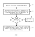
- FIG. 8 is a flow diagram illustrating at least one example of a method operational on a wireless communication device for employing a two-stage SNR estimation.
- FIG. 9 is a flow diagram illustrating at least one example of an algorithm that may be employed for the second SNR estimation of the method in FIG. 8 .
- the wireless communications system 100 is adapted to facilitate wireless communication between one or more node Bs 102 and user equipments (UEs) 104 .
- the node Bs 102 and UEs 104 may be adapted to interact with one another through wireless signals. In some instances, such wireless interaction may occur on multiple carriers (waveform signals of different frequencies). Each modulated signal may carry control information (e.g., pilot signals), overhead information, data, etc.
- the node Bs 102 can wirelessly communicate with the UEs 104 via a node B antenna.
- the node Bs 102 may each be implemented generally as a device adapted to facilitate wireless connectivity (for one or more UEs 104 ) to the wireless communications system 100 .
- Such a node B 102 may also be referred to by those skilled in the art as a base station, a base transceiver station (BTS), a radio base station, a radio transceiver, a transceiver function, a basic service set (BSS), and extended service set (ESS), a femto cell, a pico cell, or some other suitable terminology.
- the node Bs 102 are configured to communicate with the UEs 104 under the control of a radio network controller (see FIG. 2 ). Each of the node B 102 sites can provide communication coverage for a respective geographic area.
- the coverage area 106 for each node B 102 here is identified as cells 106 - a , 106 - b , or 106 - c .
- the coverage area 106 for a node B 102 may be divided into sectors (not shown, but making up only a portion of the coverage area).
- the system 100 may include node Bs 102 of different types.
- One or more UEs 104 may be dispersed throughout the coverage areas 106 . Each UE 104 may communicate with one or more node Bs 102 . A UE 104 may generally include one or more devices that communicate with one or more other devices through wireless signals.
- Such a UE 104 may also be referred to by those skilled in the art as an access terminal, a mobile station (MS), a subscriber station, a mobile unit, a subscriber unit, a wireless unit, a remote unit, a mobile device, a wireless device, a wireless communications device, a remote device, a mobile subscriber station, a mobile terminal, a wireless terminal, a remote terminal, a handset, a terminal, a user agent, a mobile client, a client, or some other suitable terminology.
- MS mobile station
- subscriber station a mobile unit, a subscriber unit, a wireless unit, a remote unit
- a mobile device a wireless device, a wireless communications device, a remote device, a mobile subscriber station, a mobile terminal, a wireless terminal, a remote terminal, a handset, a terminal, a user agent, a mobile client, a client, or some other suitable terminology.
- a UE 104 may include a mobile terminal and/or an at least substantially fixed terminal
- Examples of a UE 104 include a mobile phone, a pager, a wireless modem, a personal digital assistant, a personal information manager (PIM), a personal media player, a palmtop computer, a laptop computer, a tablet computer, a television, an appliance, an e-reader, a digital video recorder (DVR), a machine-to-machine (M2M) device, meter, entertainment device, router, and/or other communication/computing device which communicates, at least partially, through a wireless or cellular network.
- PIM personal information manager
- DVR digital video recorder
- M2M machine-to-machine
- FIG. 2 a block diagram illustrating select components of the wireless communication system 100 is depicted according to at least one example.
- the node Bs 102 are included as at least a part of a radio access network (RAN) 202 .
- the radio access network (RAN) 202 is generally adapted to manage traffic and signaling between one or more UEs 104 and one or more other network entities, such as network entities included in a core network 204 .
- the radio access network 202 may, according to various implementations, be referred to by those skill in the art as a UMTS Terrestrial Radio Access Network (UTRAN), a base station subsystem (BSS), an access network, a GSM Edge Radio Access Network (GERAN), etc.
- UTRAN UMTS Terrestrial Radio Access Network
- BSS base station subsystem
- GERAN GSM Edge Radio Access Network
- the radio access network 202 can include a radio network controller (RNC) 206 , which may also be referred to by those of skill in the art as a base station controller (BSC).
- RNC radio network controller
- BSC base station controller
- the radio network controller 206 is generally responsible for the establishment, release, and maintenance of wireless connections within one or more coverage areas associated with the one or more node Bs 102 which are connected to the radio network controller 206 .
- the radio network controller 206 can be communicatively coupled to one or more nodes or entities of the core network 204 .
- the core network 204 is a portion of the wireless communications system 100 that provides various services to UEs 104 that are connected via the radio access network 202 .
- the core network 204 may include a circuit-switched (CS) domain and a packet-switched (PS) domain.
- Some examples of circuit-switched entities include a mobile switching center (MSC) and visitor location register (VLR), identified as MSC/VLR 208 , as well as a Gateway MSC (GMSC) 210 .
- Some examples of packet-switched elements include a Serving GPRS Support Node (SGSN) 212 and a Gateway GPRS Support Node (GGSN) 214 .
- SGSN Serving GPRS Support Node
- GGSN Gateway GPRS Support Node
- a UE 104 can obtain access to a public switched telephone network (PSTN) 216 via the circuit-switched domain, and to an IP network 218 via the packet-switched domain.
- PSTN public switched telephone network
- Quadrature phase-shift keying also known as I-Q/code multiplexing
- I-Q/code multiplexing is a modulation technique in which a 2-bit symbol is encoded by controlling the phase of two carrier waves, referred to as an in-phase (I) carrier and a quadrature (Q) carrier.
- each transmitted symbol s k is modified according to noise, interference, and/or characteristics of the channel, as represented by n k .
- n k for each sample represents a complex, independent and identically distributed (i.i.d.) variable with independent real and imaginary parts, having a variance of ⁇ 2 on each axis, and also independent of the QPSK signaling.
- 2 ] E s +I oc .
- FIG. 4 is a schematic diagram of an exemplary set of received symbols r k , showing that they may be rather substantially altered from the transmitted symbols s k , and the estimation of what symbol is intended to be represented by each received symbol may tend to be problematic.
- SNR estimation is typically used for power control, to maintain the required link quality while using the minimum transmitted power.
- a wireless communications devices e.g., a node B 102 , a UE 104
- a wireless communications devices will estimate the SNR using a technique based on characteristics of dedicated pilot symbols.
- techniques for SNR estimation can result in noisy estimates with a high variance.
- wireless communications devices are adapted to employ a blind SNR estimation technique.
- Such blind SNR estimation techniques of the present disclosure may utilize raw data symbols to compute an SNR estimate.
- the blind SNR estimation techniques disclosed herein may rely solely upon the data symbols, and in other examples, the blind SNR estimation techniques disclosed herein may combine SNR estimation based on data with SNR estimation based on dedicated pilots.
- the blind SNR estimation techniques of the present disclosure may be utilized to adapt a demodulation algorithm for demodulating received symbols, e.g., QPSK symbols.
- the SNR estimates provided herein may be utilized for any other suitable purpose, including but not limited to power control of the received transmission.
- FIG. 5 a block diagram is shown illustrating select components of a wireless communication device 500 according to at least one example of the present disclosure.
- the wireless communication device 500 may be implemented, for example, as a node B 102 or a UE 104 of FIGS. 1 and 2 , as well as other wireless communication devices.
- the wireless communication device 500 includes a communications interface 502 and a storage medium 504 .
- the communications interface 502 and the storage medium 504 can both be coupled to or placed in electrical communication with a processing circuit 506 .
- the communications interface 502 is configured as an interface for wireless communications mediums.
- the communications interface 502 may be configured to communicate information bi-directionally with respect to other communications devices in a network.
- the communications interface 502 may be coupled with an antenna (not shown) for facilitating reception and transmission of wireless communications.
- the storage medium 504 may represent one or more processor-readable devices for storing programming, such as processor executable code or instructions (e.g., software, firmware), electronic data, databases, or other digital information.
- the storage medium 504 may also be used for storing data that is manipulated by the processing circuit 506 when executing programming.
- the storage medium 504 may be any available media that can be accessed by a general purpose or special purpose processor, including portable or fixed storage devices, optical storage devices, and various other mediums capable of storing, containing and/or carrying programming.
- the storage medium 504 may include a computer-readable, machine-readable, and/or processor-readable storage medium such as a magnetic storage device (e.g., hard disk, floppy disk, magnetic strip), an optical storage medium (e.g., compact disk (CD), digital versatile disk (DVD)), a smart card, a flash memory device (e.g., card, stick, key drive), random access memory (RAM), read only memory (ROM), programmable ROM (PROM), erasable PROM (EPROM), electrically erasable PROM (EEPROM), a register, a removable disk, and/or other mediums for storing programming, as well as any combination thereof.
- a magnetic storage device e.g., hard disk, floppy disk, magnetic strip
- an optical storage medium e.g., compact disk (CD), digital versatile disk (DVD)
- a smart card e.g., a flash memory device (e.g., card, stick, key drive), random access memory (RAM), read only memory (ROM),
- the storage medium 504 may be coupled to the processing circuit 506 such that the processing circuit 506 can read information from, and write information to, the storage medium 504 . That is, the storage medium 504 can be coupled to the processing circuit 506 so that the storage medium 504 is at least accessible by the processing circuit 506 , including examples where the storage medium 504 is integral to the processing circuit 506 and/or examples where the storage medium 504 is separate from the processing circuit 506 (e.g., resident in the wireless communication device 500 , external to the wireless communication device 500 , distributed across multiple entities).
- Programming stored by the storage medium 504 when executed by the processing circuit 506 , causes the processing circuit 506 to perform one or more of the various functions and/or process steps described herein.
- the processing circuit 506 is adapted for processing, including the execution of programming, which may be stored on the storage medium 504 .
- programming shall be construed broadly to include without limitation instructions, instruction sets, code, code segments, program code, programs, subprograms, software modules, applications, software applications, software packages, routines, subroutines, objects, executables, threads of execution, procedures, functions, etc., whether referred to as software, firmware, middleware, microcode, hardware description language, or otherwise.
- any reference to programming in relation to one or more features of the processing circuit 506 can include programming stored by the storage medium 504 .
- the storage medium 504 may include signal-to-noise ratio (SNR) estimation operations 508 .
- SNR estimation operations 508 are adapted to cause the processing circuit 506 to estimate the signal-to-noise ratio for received transmission, as described herein.
- the processing circuit 506 is arranged to obtain, process and/or send data, control data access and storage, issue commands, and control other desired operations.
- the processing circuit 506 may include circuitry adapted to implement desired programming provided by appropriate media in at least one example.
- the processing circuit 506 may be implemented as one or more processors, one or more controllers, and/or other structure configured to execute executable programming Examples of the processing circuit 506 may include a general purpose processor, a digital signal processor (DSP), an application specific integrated circuit (ASIC), a field programmable gate array (FPGA) or other programmable logic component, discrete gate or transistor logic, discrete hardware components, or any combination thereof designed to perform the functions described herein.
- DSP digital signal processor
- ASIC application specific integrated circuit
- FPGA field programmable gate array
- a general purpose processor may include a microprocessor, as well as any conventional processor, controller, microcontroller, or state machine.
- the processing circuit 506 may also be implemented as a combination of computing components, such as a combination of a DSP and a microprocessor, a number of microprocessors, one or more microprocessors in conjunction with a DSP core, an ASIC and a microprocessor, or any other number of varying configurations. These examples of the processing circuit 506 are for illustration and other suitable configurations within the scope of the present disclosure are also contemplated.
- the processing circuit 506 may be adapted to perform any or all of the processes, functions, steps and/or routines for any or all of the communications devices described herein (e.g., node B 102 , UE 104 , wireless communication device 500 ).
- the term “adapted” in relation to the processing circuit 506 may refer to the processing circuit 506 being one or more of configured, employed, implemented, and/or programmed (in conjunction with the storage medium 506 ) to perform a particular process, function, step and/or routine according to various features described herein.
- the processing circuit 506 may include a transmitter 510 and a receiver 512 for facilitating bi-directional communications with one or more other devices.
- the transmitter circuit/module 510 may also be referred to as a transmit processor, a transmit frame processor, a transmit circuit, a transmitter chain, and/or other suitable terminology by those skilled in the art.
- the transmitter circuit/module 510 may include circuitry and/or programming adapted to provide various signal processing functions for transmitting data.
- the transmitter circuit/module 510 can be adapted to provide cyclic redundancy check (CRC) codes for error detection, coding and interleaving to facilitate forward error correction (FEC), mapping to signal constellations based on various modulation schemes (e.g., quadrature phase-shift keying (QPSK)), spreading with orthogonal variable spreading factors (OVSF), and multiplying with scrambling codes to produce a series of symbols.
- CRC cyclic redundancy check
- FEC forward error correction
- mapping to signal constellations based on various modulation schemes (e.g., quadrature phase-shift keying (QPSK)), spreading with orthogonal variable spreading factors (OVSF), and multiply
- the transmitter circuit/module 510 may further employ the generated symbols to create a frame structure by multiplexing the symbols, resulting in a series of frames.
- the frames are then provided by the transmitter circuit/module 510 to the communications interface 502 , which may provide various signal conditioning functions including amplifying, filtering, and modulating the frames onto a carrier for downlink transmission over the wireless medium through an antenna.
- the receiver 512 which may also be referred to by those skilled in the art as a receive processor, receive frame processor, channel processor, receive circuit, receiver chain, and/or other suitable terminology, may include circuitry and/or programming adapted to provide various signal processing functions for recovering transmitted data.
- the receiver 512 is adapted to employ the SNR estimation operations 508 to determine or estimate signal-to-noise ratios associated with received symbols as a part of the process for recovering transmitted data.
- FIG. 6 is a block diagram illustrating select components of at least one example of a receiver 512 .
- the receiver 512 includes a Rake component 602 , a CCC 604 , a demodulator 606 , a blind, power & noise (BP&N) estimator 608 , and an inner loop power controller (ILPC) 610 .
- a Rake component 602 the receiver 512 includes a Rake component 602 , a CCC 604 , a demodulator 606 , a blind, power & noise (BP&N) estimator 608 , and an inner loop power controller (ILPC) 610 .
- BP&N power & noise estimator
- ILPC inner loop power controller
- the Rake component 602 may represent circuitry and/or programming adapted to receive multipath transmissions.
- the Rake component 602 can include a plurality of fingers for receiving transmission over a multipath channel.
- the Rake component 602 may generate an estimate of signal power, based on dedicated pilots, and an estimate of noise power based on a CPICH pilot transmission. These estimates may be conveyed to the ILPC 610 .
- the CCC 604 represents circuitry and/or programming adapted to perform cross cell combining
- the demodulator 606 represents circuitry and/or programming adapted for de-rate matching, deinterleaving and decoding.
- the blind power & noise (BP&N) estimator 608 represents circuitry and/or programming adapted to obtain noisy symbols before the demodulator 606 , and estimate both the noise power and the signal power.
- the BP&N estimator 608 may obtain symbols, such as the symbols in the QPSK constellation in FIG. 4 , and estimate both the noise and the signal power associated with the obtained symbols according to one or more of the SNR estimation techniques described herein.
- the inner loop power controller (ILPC) 610 represents circuitry and/or programming adapted to implement a final estimation of the SNR.
- the ILPC 610 may implement the final estimation of the SNR as a combination of the estimates from the Rake component 602 and from the BP&N estimator 608 .
- the receiver 512 may employ a maximum likelihood SNR calculation or estimation on the received symbols to estimate both the noise and the signal power, where the maximum likelihood SNR calculation is adapted to achieve the Cramér-Rao bound for SNR estimation.
- the Cramér-Rao bound expresses a lower bound on the variance of estimators of a deterministic parameter. In its simplest form, the bound states that the variance of any unbiased estimator is at least as high as the inverse of the Fisher information. An unbiased estimator which achieves this lower bound is said to be fully efficient. Such a solution achieves the lowest possible mean squared error among all unbiased methods, and is therefore the minimum variance unbiased (MVU) estimator.
- MVU minimum variance unbiased
- the maximum likelihood (ML) SNR calculation may be based on an iterative solution of the maximum likelihood equation set forth below.
- FIG. 7 a flow diagram is depicted illustrating at least one example of a method operational on a wireless communication device, such as the wireless communication device 500 , employing the ML SNR calculation described herein.
- the wireless communication device 500 can receive a plurality of data symbols at 702 .
- the receiver 512 may receive a plurality of QPSK data symbols via the communications interface 502 .
- FIG. 4 is a graphical illustration of QPSK data symbols that may be received by the receiver 512 via the communications interface 502 .
- the wireless communication device 500 may iteratively compute an amplitude value ‘A’ for the plurality of data symbols at 704 .
- the receiver 512 executing the SNR estimation operations 508 may calculate a weighted mean of the amplitude ‘A’ for each data symbol, where each of the four quadrants referred to above with reference to FIG. 4 contribute differently to the weighted mean according to the probability that the data symbol is within each respective quadrant.
- the resulting weighted means of the amplitudes ‘A’ derived for each received data symbol can then be used to calculate an arithmetic mean.
- the receiver 512 executing the SNR estimation operations 508 may calculate the amplitude value ‘A’ for the plurality of data symbols according to the following fixed-point equation:
- the total power ‘M 2 ’ including the signal and the noise, can be estimated by the equation:
- the above equation for ‘A’ may be solved iteratively, for example, utilizing a suitable initial starting point ‘A 0 ’.
- ⁇ s,ub ⁇ s /(b+1)
- any suitable number of iterations may be utilized.
- the equation may be iterated up to selected threshold, e.g.,
- a predetermined number of iterations may be utilized.
- the wireless communication device 500 can compute a signal-to-noise ratio based on the iteratively computed amplitude value ‘A’.
- a two-stage procedure may be implemented, whereby a less computationally-complex decision directed estimation is employed first. If the decision directed estimation is sufficient, then the wireless communication device 500 may use the results for the SNR estimation in processing the received data symbols. If the decision directed estimation is not sufficient, then the wireless communication device 500 can perform a second stage calculation, which can include a maximum likelihood calculation in at least some scenarios.
- FIG. 8 is a flow diagram illustrating at least one example of a method operational on a wireless communication device, such as the wireless communication device 500 , for employing a two-stage SNR estimation.
- a wireless communication device 500 can receive a plurality of data symbols at 802 .
- the receiver 512 may receive a plurality of QPSK data symbols via the communications interface 502 .
- FIG. 4 is a graphical illustration of QPSK data symbols that may be received by the receiver 512 via the communications interface 502 .
- the wireless communication device 500 can determine a first estimate of the signal-to-noise ratio based on a first estimated signal power and a first estimated noise power associated with the plurality of received data symbols.
- the receiver 512 executing the SNR estimation operations 508 may compute a first estimate of signal power ‘ ⁇ s ’ and noise power ‘Î oc ’ utilizing a decision-directed estimation procedure.
- the estimates of the signal power ‘E s ’ and the noise power ‘Î oc ’ may be computed from the received symbols ‘r k ’ according to, E[
- ] E[
- ] A 2 +2 ⁇ 2
- the expectations in the above equation may be replaced with their corresponding temporal averages, yielding the total power equation referred to above:
- the energy estimation of the received symbols may correspond to the mean of the real and imaginary parts. That is,
- the first estimation ‘ ⁇ circumflex over ( ⁇ ) ⁇ ’ of the SNR corresponds to:
- This first estimate can provide a computationally simple algorithm for providing a first SNR estimation, utilizing a relatively lower computational complexity than the maximum likelihood computation described previously. In particularly high SNR conditions, this first stage can perform sufficiently well for the SNR estimation. Accordingly, the wireless communications device 500 can determine whether the first estimate of the SNR is above a predetermined threshold at step 806 .
- the receiver 512 executing the SNR estimation operations 508 may compare the first SNR estimation to a predetermined threshold.
- the threshold may be about 10 (e.g., ⁇ circumflex over ( ⁇ ) ⁇ >10), although any suitable threshold value may be utilized within the scope of the present disclosure.
- the wireless communication device 500 can return the first estimates of signal power and noise power for processing the data symbols, at step 808 .
- the wireless communication device 500 can determine a second estimate of a SNR based on second estimates of signal power and noise power associated with the received data symbols, at step 810 .
- the receiver 512 executing the SNR estimation operations 508 may compute second estimates for signal power and noise power.
- the second estimates may be calculated in a manner to achieve better performance, especially in low SNR conditions.
- the maximum likelihood SNR calculation may be employed in the second estimation.
- an additional computation referred to herein as a Z-method calculation, may also be available for the second SNR estimate computations.
- the particular computation employed to obtain the second SNR estimate may depend on the number of samples received at the receiver 512 .
- the Z-method calculation which will be described in more detail below, is computationally simpler than the maximum likelihood calculation described above.
- FIG. 9 is a flow diagram illustrating at least one example of an algorithm 900 that may be employed for the second SNR estimation of step 810 in FIG. 8 .
- the receiver 512 executing the SNR estimation operations 508 may determine whether the number of samples received is above some threshold.
- the threshold for the number of samples may be about 128 samples, as it has been observed that the maximum likelihood SNR calculation and the Z-method calculation achieve at least substantially similar performance with this number of samples.
- the threshold number of samples for selecting between the maximum likelihood SNR calculation and the Z-method calculation may be set to any suitable value.
- the receiver 512 executing the SNR estimation operations 508 can employ the maximum likelihood SNR calculation described above. That is, at operation 904 , the receiver 512 executing the SNR estimation operations 508 can compute a suitable starting point ‘A 0 ’ for an iterative solution for the second SNR estimate. At operation 906 , the receiver 512 executing the SNR estimation operations 508 may iteratively compute an amplitude value ‘A’, either up to a selected threshold e.g.,
- the receiver 512 executing the SNR estimation operations 508 may compute second estimate of signal power ‘ ⁇ s ’ and noise power ‘Î oc ’ utilizing the iteratively computed amplitude value ‘A’, and with these values, may generate a second SNR estimate ‘ ⁇ circumflex over ( ⁇ ) ⁇ .’
- the receiver 512 executing the SNR estimation operations 508 can employ the so-called Z-method calculations.
- the Z-method for SNR estimation may be based on fourth and second moment statistics. That is, the second and fourth moments may be utilized to establish a relation between the observations r k and the SNR.
- the Z-method estimation is generally a Kurtosis calculation. Accordingly, the Z-method estimation can be generally defined as a measure reflecting the degree to which a distribution is peaked. That is, the Z-method estimation provides information regarding the height of the distribution relative to the value of its standard deviation.
- the receiver 512 executing the SNR estimation operations 508 may compute a Kurtosis, or fourth standardized moment z, depending on the QPSK modulation.
- the fourth standardized moment z may be calculated according to the ratio:
- the receiver 512 executing the SNR estimation operations 508 can compute the second SNR estimate at operation 912 .
- This SNR estimation algorithm can provide a rough estimation.
- the value of the SNR estimate ‘ ⁇ ’ as a function of z may corresponds to the following:
- the expectations may be replaced with their corresponding temporal averages, as follows:
- the receiver 512 executing the SNR estimation operations 508 can compute the signal power ‘ ⁇ s ’ and noise power ‘Î oc ’ estimates from the SNR ‘ ⁇ ’ at operation 914 , according to the following equations:
- wireless communication devices can achieve relatively accurate estimates in both high and low signal-to-noise ratio conditions. Furthermore, various aspects may enable such accurate estimates with relatively reduced computational complexity.
- FIGS. 1 , 2 , 3 , 4 , 5 , 6 , 7 , 8 , and/or 9 may be rearranged and/or combined into a single component, step, feature or function or embodied in several components, steps, or functions. Additional elements, components, steps, and/or functions may also be added or not utilized without departing from the present disclosure.
- the apparatus, devices and/or components illustrated in FIGS. 1 , 2 , 5 , and/or 6 may be configured to perform or employ one or more of the methods, features, parameters, and/or steps described in FIGS. 3 , 4 , 7 , 8 , and/or 9 .
- the novel algorithms described herein may also be efficiently implemented in software and/or embedded in hardware.
- a process is terminated when its operations are completed.
- a process may correspond to a method, a function, a procedure, a subroutine, a subprogram, etc.
- a process corresponds to a function
- its termination corresponds to a return of the function to the calling function or the main function.
Landscapes
- Engineering & Computer Science (AREA)
- Computer Networks & Wireless Communication (AREA)
- Signal Processing (AREA)
- Quality & Reliability (AREA)
- Physics & Mathematics (AREA)
- Electromagnetism (AREA)
- Mobile Radio Communication Systems (AREA)
Abstract
Description
each of which may occur with equal probability. Here, A represents the amplitude of the vector, wherein A=√Es, and wherein Es represents the signal energy. Equivalently, it may be said that each transmitted symbol has a value of ±a ±ja, where j represents √(−1), and where a=√(Es/2).
α1,k
α2,k
α3,k
α4,k
E[|r k 2 |]=E[|Ae jφ
Î oc =M 2 −Ê s.
as described above.
SNR
where d0=4.1, d1=0.4, d2=4.07, and d3=9.87·10−4.
E[n I 2]=σ2;
E[n I 3]=0;
E[n I 4]=3σ4;
E[n Q 2]=σ2;
E[n Q 3]=0; and
E[n Q 4]=3σ4,
it can be found that the value of z relates to the SNR ‘γ’ as follows:
Claims (24)
Priority Applications (2)
| Application Number | Priority Date | Filing Date | Title |
|---|---|---|---|
| US14/048,709 US8995516B2 (en) | 2012-12-17 | 2013-10-08 | Devices and methods for facilitating signal-to-noise ratio estimation of received wireless transmissions |
| PCT/US2013/073872 WO2014099447A1 (en) | 2012-12-17 | 2013-12-09 | Devices and methods for facilitating signal-to-noise ratio estimation of received wireless transmissions |
Applications Claiming Priority (2)
| Application Number | Priority Date | Filing Date | Title |
|---|---|---|---|
| US201261738373P | 2012-12-17 | 2012-12-17 | |
| US14/048,709 US8995516B2 (en) | 2012-12-17 | 2013-10-08 | Devices and methods for facilitating signal-to-noise ratio estimation of received wireless transmissions |
Publications (2)
| Publication Number | Publication Date |
|---|---|
| US20140169503A1 US20140169503A1 (en) | 2014-06-19 |
| US8995516B2 true US8995516B2 (en) | 2015-03-31 |
Family
ID=50930877
Family Applications (1)
| Application Number | Title | Priority Date | Filing Date |
|---|---|---|---|
| US14/048,709 Expired - Fee Related US8995516B2 (en) | 2012-12-17 | 2013-10-08 | Devices and methods for facilitating signal-to-noise ratio estimation of received wireless transmissions |
Country Status (2)
| Country | Link |
|---|---|
| US (1) | US8995516B2 (en) |
| WO (1) | WO2014099447A1 (en) |
Families Citing this family (4)
| Publication number | Priority date | Publication date | Assignee | Title |
|---|---|---|---|---|
| US9071482B2 (en) * | 2013-09-27 | 2015-06-30 | Telefonaktiebolaget L M Ericsson (Publ) | Power estimation for wireless communication devices in code division multiple access systems technical field |
| US10650621B1 (en) | 2016-09-13 | 2020-05-12 | Iocurrents, Inc. | Interfacing with a vehicular controller area network |
| IT201900002785A1 (en) * | 2019-02-26 | 2020-08-26 | Teko Telecom S R L | BASE RADIO STATION AND WIRELESS TELECOMMUNICATION PROCESS FOR HIGH MOBILITY SCENARIOS |
| CN115118362A (en) * | 2022-05-27 | 2022-09-27 | 成都中科微信息技术研究院有限公司 | Signal-to-noise ratio estimation method, medium and device suitable for millimeter wave data link |
Citations (7)
| Publication number | Priority date | Publication date | Assignee | Title |
|---|---|---|---|---|
| US20030072392A1 (en) | 2001-10-16 | 2003-04-17 | Beadle Edward R. | System and method for an in-service decision-directed signal to noise ratio estimator |
| WO2007113511A1 (en) | 2006-03-31 | 2007-10-11 | Matsushita Electric Industrial Co. Ltd. | Signal-to-noise ratio estimation for digital signal decoding |
| US7310369B1 (en) | 2000-12-15 | 2007-12-18 | Conexant Systems, Inc. | SNR-related parameter estimation method and system |
| WO2008005073A1 (en) | 2006-06-30 | 2008-01-10 | Intel Corporation | Signal-to-noise ratio (snr) determination in the time domain |
| US20100054319A1 (en) | 2006-11-30 | 2010-03-04 | Keun-Moo Lee | Ofdm wireless mobile communication system and method for estimating snr of channel thereof |
| US7764730B2 (en) | 2002-04-03 | 2010-07-27 | Interdigital Technology Corporation | Low bias estimation of small signal-to-noise ratio |
| US20110188561A1 (en) | 2008-10-06 | 2011-08-04 | Ceragon Networks Ltd | Snr estimation |
-
2013
- 2013-10-08 US US14/048,709 patent/US8995516B2/en not_active Expired - Fee Related
- 2013-12-09 WO PCT/US2013/073872 patent/WO2014099447A1/en not_active Ceased
Patent Citations (7)
| Publication number | Priority date | Publication date | Assignee | Title |
|---|---|---|---|---|
| US7310369B1 (en) | 2000-12-15 | 2007-12-18 | Conexant Systems, Inc. | SNR-related parameter estimation method and system |
| US20030072392A1 (en) | 2001-10-16 | 2003-04-17 | Beadle Edward R. | System and method for an in-service decision-directed signal to noise ratio estimator |
| US7764730B2 (en) | 2002-04-03 | 2010-07-27 | Interdigital Technology Corporation | Low bias estimation of small signal-to-noise ratio |
| WO2007113511A1 (en) | 2006-03-31 | 2007-10-11 | Matsushita Electric Industrial Co. Ltd. | Signal-to-noise ratio estimation for digital signal decoding |
| WO2008005073A1 (en) | 2006-06-30 | 2008-01-10 | Intel Corporation | Signal-to-noise ratio (snr) determination in the time domain |
| US20100054319A1 (en) | 2006-11-30 | 2010-03-04 | Keun-Moo Lee | Ofdm wireless mobile communication system and method for estimating snr of channel thereof |
| US20110188561A1 (en) | 2008-10-06 | 2011-08-04 | Ceragon Networks Ltd | Snr estimation |
Non-Patent Citations (13)
| Title |
|---|
| A. Ramesh, et al.; SNR Estimation in Nakagami-m Fading With Diversity Combining and Its Application to Turbo Decoding; IEEE Transactions on Communications, vol. 50, No. 11, Nov. 2002, pp. 1719-1724. |
| Alvarez-Diaz M. et al., "SNR Estimation for Multilevel Constellations Using Higher-Order Moments", IEEE Transactions on Signal Processing, Mar. 1, 2010, IEEE Service Center, New York, NY, US, vol. 58, No. 3, pp. 1515-1526, XP011297221, ISSN: 1053-587X. |
| Bin Li, et al.; A Low Bias Algorithm to Estimate Negative SNRs in an AWGN Channel; IEEE Communications Letters, vol. 6, No. 11, Nov. 2002, pp. 469-471. |
| Bin Li, et al.; New Results on SNR Estimation of MPSK Modulated Signals; The 14th IEEE 2003 International Symposium on Personal, Indoor and Mobile Radio Communication Proceedings; pp. 2373-2377. |
| Dong-Joon Shin, et al.; Simple SNR Estimation Methods for QPSK Modulated Short Bursts; IEEE, 2001, pp. 3644-3647. |
| Gappmair et al ("ML and EM algorithm for non-data-aided SNR estimation of linearly modulated signals", 6th International Symposium on Communication Systems, Networks and Digital Signal Processing (CNSDSP), Jul. 25, 2008, IEEE, Piscataway, N J, USA, pp. 530-534, XP031314839, ISBN: 978-1-4244-1875-6). * |
| Gappmair W. et al., "ML and EM algorithm for non-data-aided SNR estimation of linearly modulated signals", 6th International Symposium on Communication Systems, Networks and Digital Signal Processing (CNSDSP), Jul. 25, 2008, IEEE, Piscataway, NJ, USA, pp. 530-534, XP031314839, ISBN: 978-1-4244-1875-6. |
| Hua Xu, et al.; The Simple SNR Estimation Algorithms for MPSK Signals; ICSP'04 Proceedings; pp. 1781-1785. |
| Ijaz A. et al., "Signal-to-Noise Ratio Estimation Algorithm for Advanced DVB-RCS Systems", IEEE Transactions on Broadcasting, Dec. 1, 2012, IEEE Service Center, Piscataway, NJ, US, vol. 58, No. 4, pp. 603-608, XP011472242, ISSN: 0018-9316, DOI: 10.1109/TBC.2012.2218074. |
| International Search Report and Written Opinion-PCT/US2013/073872-ISA/EPO-Feb. 24, 2014. |
| Norman C. Beaulieu, et al.; Comparison of Four SNR Estimators for QPSK Modulations; IEEE Communications Letters, vol. 4, No. 2, Feb. 2000, pp. 43-45. |
| Pauluzzi D. R. et al., "A comparison of SNR estimation techniques for the AWGN channel", IEEE Transactions on Communications, Oct. 1, 2000, IEEE Service Center, Piscataway, NJ. USA, vol. 48, No. 10, pp. 1681-1691, XP011009781, ISSN: 0090-6778, DOI: 10.1109/26.871393. |
| Wang A. et al., "Comparison of Several SNR Estimators for QPSK Modulations", International Conference on Computer Science & Service System (CSSS), Aug. 11, 2012, IEEE, pp. 77-80, XP032295014, DOI: 10.1109/CSSS.2012.28 ISBN: 978-1-4673-0721-5. |
Also Published As
| Publication number | Publication date |
|---|---|
| US20140169503A1 (en) | 2014-06-19 |
| WO2014099447A1 (en) | 2014-06-26 |
Similar Documents
| Publication | Publication Date | Title |
|---|---|---|
| JP5562971B2 (en) | Method and system for reduced complexity channel estimation and interference cancellation for V-MIMO demodulation | |
| US9351176B2 (en) | Phase and amplitude tracking in the presence of a walking pilot signal | |
| US8526319B2 (en) | Reporting of channel quality indicators for a non-linear detector | |
| US8774248B2 (en) | Receiver for MUROS adapted to estimate symbol constellation using training sequences from two sub-channels | |
| CN104272691B (en) | Support the signaling and relevant device and method of advanced wireless receiver | |
| EP1198938B1 (en) | Fading Resistant Multi-Level QAM Receiver | |
| US9838159B2 (en) | Correction of demodulation errors based on machine learning | |
| US8582703B2 (en) | Estimation of signal and interference power | |
| US7035343B2 (en) | Closed loop transmit diversity antenna verification using trellis decoding | |
| US8995516B2 (en) | Devices and methods for facilitating signal-to-noise ratio estimation of received wireless transmissions | |
| WO2011073915A2 (en) | Hybrid correlation and least squares channel estimation | |
| US9602242B2 (en) | Coherent reception with noisy channel state information | |
| US9225566B2 (en) | Frequency offset estimation in communication devices | |
| US9112660B2 (en) | Maximum likelihood detection | |
| US8774261B2 (en) | Soft linear and non-linear interference cancellation | |
| US20140185591A1 (en) | Power control with dynamic timing update | |
| US7457379B2 (en) | Adaptive multi-step combined DC offset compensation for EDGE 8-PSK | |
| US20160043824A1 (en) | Segmented data-aided frequency estimation in td-scdma | |
| US8290090B2 (en) | Blind amplitude estimation for received symbols | |
| US9510218B2 (en) | Devices and methods for facilitating closed-loop transmission diversity in wireless communications systems | |
| Nawaz et al. | Spectral re-harvesting for 4G networks: Through low-complexity VAMOS receiver design | |
| Cheng | Modeling Coding Performance with Nonideal Channel Estimation for Dynamic System Simulators |
Legal Events
| Date | Code | Title | Description |
|---|---|---|---|
| AS | Assignment |
Owner name: QUALCOMM INCORPORATED, CALIFORNIA Free format text: ASSIGNMENT OF ASSIGNORS INTEREST;ASSIGNOR:COHEN, ROEE;REEL/FRAME:031429/0120 Effective date: 20131008 |
|
| FEPP | Fee payment procedure |
Free format text: PAYOR NUMBER ASSIGNED (ORIGINAL EVENT CODE: ASPN); ENTITY STATUS OF PATENT OWNER: LARGE ENTITY |
|
| STCF | Information on status: patent grant |
Free format text: PATENTED CASE |
|
| FEPP | Fee payment procedure |
Free format text: MAINTENANCE FEE REMINDER MAILED (ORIGINAL EVENT CODE: REM.); ENTITY STATUS OF PATENT OWNER: LARGE ENTITY |
|
| LAPS | Lapse for failure to pay maintenance fees |
Free format text: PATENT EXPIRED FOR FAILURE TO PAY MAINTENANCE FEES (ORIGINAL EVENT CODE: EXP.); ENTITY STATUS OF PATENT OWNER: LARGE ENTITY |
|
| STCH | Information on status: patent discontinuation |
Free format text: PATENT EXPIRED DUE TO NONPAYMENT OF MAINTENANCE FEES UNDER 37 CFR 1.362 |
|
| FP | Lapsed due to failure to pay maintenance fee |
Effective date: 20190331 |